
Projectile penetration of sandwich panels with multiple ... · sandwich panels with multiple...
15
Projectile penetration of sandwich panels with multiple suppressive cores M. Y. Laissy 1 , W. A. Attia 2 & M. M. Abdel-Wahab 3 1 Faculty of Engineering, MTI University, Egypt 2 Faculty of Engineering, Cairo University, Egypt 3 Technical Research Institute, Egyptian Armed Forces, Egypt Abstract Concrete structures are employed extensively as protective structures. This concept does not guarantee economic benefits to reduce the construction time or cost. An important issue is how the penetration distance will be affected when sandwich panels with multiple suppressive cores are used. This paper presents the development of an accurate finite element model using AUTODYN to study the behaviour of different sandwich panels exposed to 23 mm projectile. Concrete and steel are modelled as Lagrangian meshes while air is modelled as Eulerian mesh. Experiments and numerical analysis were carried out to examine the penetration depth of the different suppressive cores used. As a result, this paper will prove the benefits of using sandwich panels with multiple suppressive cores in reducing the penetration depth of the 23 mm projectile. Experimental results validate the presented models. Further experiments are required to validate the effect of the steel angles arrangement presented herein. Keywords: sandwich panels, suppressive core, penetration, concrete, projectiles. 1 Introduction Reinforced concrete and steel are still the most common materials used as protective structures, since massive concrete structures withstand blast waves and fragment impacts effectively; they are often used as protective structures according to Swedish Shelter Regulations [1]. The traditional design of structures under the impact loads is a cumbersome process and it takes a great effort to complete the computations. So, the output of the final traditional design Projectile Impacts: modelling techniques and target performance assessment 203 www.witpress.com, ISSN 1755-8336 (on-line) WIT Transactions on State of the Art in Science and Engineering, Vol 75, © 2014 WIT Press doi:10.2495/978-1-84564-879-4/020
Transcript of Projectile penetration of sandwich panels with multiple ... · sandwich panels with multiple...
Projectile penetration of sandwich panels with multiple suppressive cores
M. Y. Laissy1, W. A. Attia2 & M. M. Abdel-Wahab3 1Faculty of Engineering, MTI University, Egypt 2Faculty of Engineering, Cairo University, Egypt 3Technical Research Institute, Egyptian Armed Forces, Egypt
Abstract
Concrete structures are employed extensively as protective structures. This concept does not guarantee economic benefits to reduce the construction time or cost. An important issue is how the penetration distance will be affected when sandwich panels with multiple suppressive cores are used. This paper presents the development of an accurate finite element model using AUTODYN to study the behaviour of different sandwich panels exposed to 23 mm projectile. Concrete and steel are modelled as Lagrangian meshes while air is modelled as Eulerian mesh. Experiments and numerical analysis were carried out to examine the penetration depth of the different suppressive cores used. As a result, this paper will prove the benefits of using sandwich panels with multiple suppressive cores in reducing the penetration depth of the 23 mm projectile. Experimental results validate the presented models. Further experiments are required to validate the effect of the steel angles arrangement presented herein. Keywords: sandwich panels, suppressive core, penetration, concrete, projectiles.
1 Introduction
Reinforced concrete and steel are still the most common materials used as protective structures, since massive concrete structures withstand blast waves and fragment impacts effectively; they are often used as protective structures according to Swedish Shelter Regulations [1]. The traditional design of structures under the impact loads is a cumbersome process and it takes a great effort to complete the computations. So, the output of the final traditional design
Projectile Impacts: modelling techniques and target performance assessment 203
www.witpress.com, ISSN 1755-8336 (on-line) WIT Transactions on State of the Art in Science and Engineering, Vol 75, © 2014 WIT Press
doi:10.2495/978-1-84564-879-4/020
results in too much weight for steel and concrete elements, which causes many problems concerning the cost, time and effort required to establish a site. A concrete structure subjected to impact loading will have a different response from those statically loaded. When fragments fly into a concrete target, spalling occurs in the front of the concrete surface as a result of the direct impact. The purpose of this paper is to study the response of sandwich panels with multiple suppressive cores exposed to heavy dynamic loads and to show such panels to be of reasonable weight and high resistance against impact loads. In order to achieve a better understanding of the effect of impact loads on the suppressive materials during the penetration process, it was very essential to develop finite element models of the experimental specimens. The software package AUTODYN-3D is used in simulating the penetration of projectiles into these specimens. The primary objective of this paper is to study the ability of sandwich panels with multiple suppressive cores to resist the penetration of 23 mm projectile. Numerical and experimental data on penetration into sandwich panels and the penetration depth will be reported and illustrated.
2 Projectile penetration and perforation
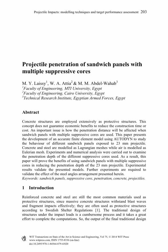
The penetration of projectiles into targets involves complex mechanical interactions. By convention [2] the following simplifying definition is adopted. When a projectile enters a target but does not pass through, it is said that this projectile has ‘penetrated’. On the other hand, when a projectile passes completely through a target, it is said that it has ‘perforated’. The depth of penetration is given by the distance as shown in fig. 1.
Figure 1: Penetration and perforation phenomena.
3 Experimental set up
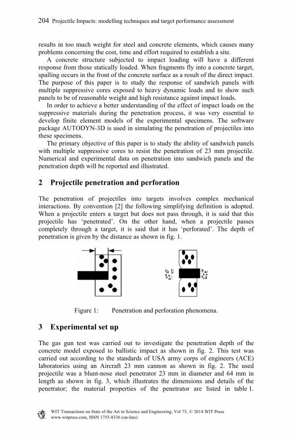
The gas gun test was carried out to investigate the penetration depth of the concrete model exposed to ballistic impact as shown in fig. 2. This test was carried out according to the standards of USA army corps of engineers (ACE) laboratories using an Aircraft 23 mm cannon as shown in fig. 2. The used projectile was a blunt-nose steel penetrator 23 mm in diameter and 64 mm in length as shown in fig. 3, which illustrates the dimensions and details of the penetrator; the material properties of the penetrator are listed in table 1.
204 Projectile Impacts: modelling techniques and target performance assessment
www.witpress.com, ISSN 1755-8336 (on-line) WIT Transactions on State of the Art in Science and Engineering, Vol 75, © 2014 WIT Press
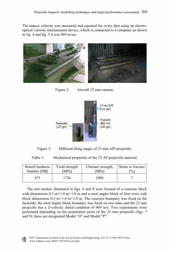
The impact velocity was measured and reported for every shot using an electro-optical velocity measurement device, which is connected to a computer as shown in fig. 4 and fig. 5 it was 969 m/sec.
Figure 2: Aircraft 23 mm cannon.
Figure 3: Different firing stages of 23 mm API projectile.
Table 1: Mechanical properties of the 23 AP projectile material.
Brinell hardness Number [HB]
Yield strength [MPa]
Ultimate strength, [MPa]
Strain to fracture [%]
475 1726 1900 7
The test models illustrated in figs. 6 and 8 were formed of a concrete block with dimensions 0.3 m×1.0 m×1.0 m and a steel angles block of four rows with block dimensions 0.3 m×1.0 m×1.0 m. The concrete boundary was fixed on the backside, the steel angles block boundary was fixed on two sides and the 23 mm projectile has a Z-velocity initial condition of 969 m/s. Two experiments were performed depending on the penetration point of the 23 mm projectile (figs. 7 and 9); these are designated Model “O” and Model “P”.
Projectile Impacts: modelling techniques and target performance assessment 205
www.witpress.com, ISSN 1755-8336 (on-line) WIT Transactions on State of the Art in Science and Engineering, Vol 75, © 2014 WIT Press
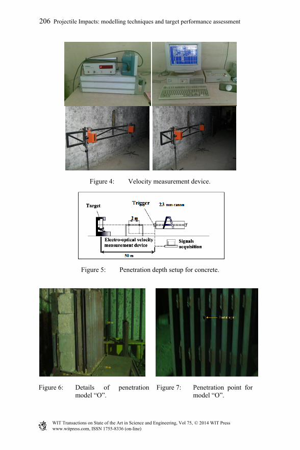
Figure 4: Velocity measurement device.
Figure 5: Penetration depth setup for concrete.
Figure 6: Details of penetration model “O”.
Figure 7: Penetration point for model “O”.
206 Projectile Impacts: modelling techniques and target performance assessment
www.witpress.com, ISSN 1755-8336 (on-line) WIT Transactions on State of the Art in Science and Engineering, Vol 75, © 2014 WIT Press
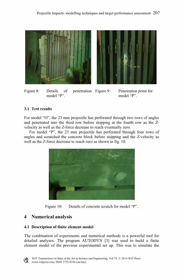
Figure 8: Details of penetration model “P”.
Figure 9: Penetration point for model “P”.
3.1 Test results
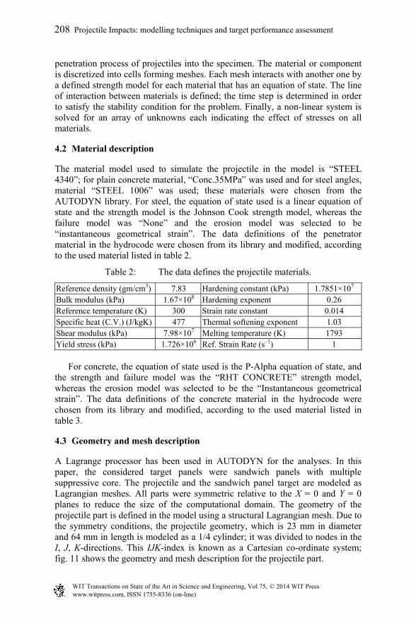
For model “O”, the 23 mm projectile has perforated through two rows of angles and penetrated into the third row before stopping at the fourth row as the Z-velocity as well as the Z-force decrease to reach eventually zero. For model “P”, the 23 mm projectile has perforated through four rows of angles and scratched the concrete block before stopping and the Z-velocity as well as the Z-force decrease to reach zero as shown in fig. 10.
Figure 10: Details of concrete scratch for model “P”.
4 Numerical analysis
4.1 Description of finite element model
The combination of experiments and numerical methods is a powerful tool for detailed analyses. The program AUTODYN [3] was used to build a finite element model of the previous experimental set up. This was to simulate the
Projectile Impacts: modelling techniques and target performance assessment 207
www.witpress.com, ISSN 1755-8336 (on-line) WIT Transactions on State of the Art in Science and Engineering, Vol 75, © 2014 WIT Press
penetration process of projectiles into the specimen. The material or component is discretized into cells forming meshes. Each mesh interacts with another one by a defined strength model for each material that has an equation of state. The line of interaction between materials is defined; the time step is determined in order to satisfy the stability condition for the problem. Finally, a non-linear system is solved for an array of unknowns each indicating the effect of stresses on all materials.
4.2 Material description
The material model used to simulate the projectile in the model is “STEEL 4340”; for plain concrete material, “Conc.35MPa” was used and for steel angles, material “STEEL 1006” was used; these materials were chosen from the AUTODYN library. For steel, the equation of state used is a linear equation of state and the strength model is the Johnson Cook strength model, whereas the failure model was “None” and the erosion model was selected to be “instantaneous geometrical strain”. The data definitions of the penetrator material in the hydrocode were chosen from its library and modified, according to the used material listed in table 2.
Table 2: The data defines the projectile materials.
Reference density (gm/cm3) 7.83 Hardening constant (kPa) 1.7851×10⁷ Bulk modulus (kPa) 1.67×10⁸ Hardening exponent 0.26 Reference temperature (K) 300 Strain rate constant 0.014 Specific heat (C.V.) (J/kgK) 477 Thermal softening exponent 1.03 Shear modulus (kPa) 7.98×10⁷ Melting temperature (K) 1793 Yield stress (kPa) 1.726×10⁶ Ref. Strain Rate (s–1) 1
For concrete, the equation of state used is the P-Alpha equation of state, and the strength and failure model was the “RHT CONCRETE” strength model, whereas the erosion model was selected to be the “Instantaneous geometrical strain”. The data definitions of the concrete material in the hydrocode were chosen from its library and modified, according to the used material listed in table 3.
4.3 Geometry and mesh description
A Lagrange processor has been used in AUTODYN for the analyses. In this paper, the considered target panels were sandwich panels with multiple suppressive core. The projectile and the sandwich panel target are modeled as Lagrangian meshes. All parts were symmetric relative to the X = 0 and Y = 0 planes to reduce the size of the computational domain. The geometry of the projectile part is defined in the model using a structural Lagrangian mesh. Due to the symmetry conditions, the projectile geometry, which is 23 mm in diameter and 64 mm in length is modeled as a 1/4 cylinder; it was divided to nodes in the I, J, K-directions. This IJK-index is known as a Cartesian co-ordinate system; fig. 11 shows the geometry and mesh description for the projectile part.
208 Projectile Impacts: modelling techniques and target performance assessment
www.witpress.com, ISSN 1755-8336 (on-line) WIT Transactions on State of the Art in Science and Engineering, Vol 75, © 2014 WIT Press
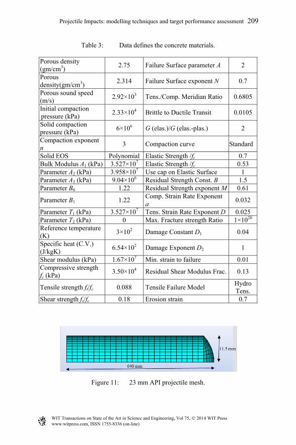
Table 3: Data defines the concrete materials.
Porous density (gm/cm3)
2.75 Failure Surface parameter A 2
Porous density(gm/cm3)
2.314 Failure Surface exponent N 0.7
Porous sound speed (m/s)
2.92×10³ Tens./Comp. Meridian Ratio 0.6805
Initial compaction pressure (kPa)
2.33×10⁴ Brittle to Ductile Transit 0.0105
Solid compaction pressure (kPa)
6×10⁶ G (elas.)/G (elas.-plas.) 2
Compaction exponent n
3 Compaction curve Standard
Solid EOS Polynomial Elastic Strength /ft 0.7 Bulk Modulus A1 (kPa) 3.527×10⁷ Elastic Strength /fc 0.53 Parameter A2 (kPa) 3.958×10⁷ Use cap on Elastic Surface 1 Parameter A3 (kPa) 9.04×10⁶ Residual Strength Const. B 1.5 Parameter B0 1.22 Residual Strength exponent M 0.61
Parameter B1 1.22 Comp. Strain Rate Exponent a
0.032
Parameter T1 (kPa) 3.527×10⁷ Tens. Strain Rate Exponent D 0.025 Parameter T2 (kPa) 0 Max. Fracture strength Ratio 1×10²⁰ Reference temperature (K)
3×10² Damage Constant D1 0.04
Specific heat (C.V.) (J/kgK)
6.54×10² Damage Exponent D2 1
Shear modulus (kPa) 1.67×10⁷ Min. strain to failure 0.01 Compressive strength fc (kPa)
3.50×10⁴ Residual Shear Modulus Frac. 0.13
Tensile strength ft/fc 0.088 Tensile Failure Model Hydro Tens.
Shear strength fs/fc 0.18 Erosion strain 0.7
Figure 11: 23 mm API projectile mesh.
Projectile Impacts: modelling techniques and target performance assessment 209
www.witpress.com, ISSN 1755-8336 (on-line) WIT Transactions on State of the Art in Science and Engineering, Vol 75, © 2014 WIT Press
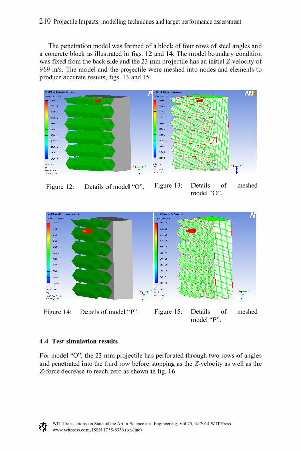
The penetration model was formed of a block of four rows of steel angles and a concrete block as illustrated in figs. 12 and 14. The model boundary condition was fixed from the back side and the 23 mm projectile has an initial Z-velocity of 969 m/s. The model and the projectile were meshed into nodes and elements to produce accurate results, figs. 13 and 15.
Figure 12: Details of model “O”. Figure 13: Details of meshed model “O”.
Figure 14: Details of model “P”. Figure 15: Details of meshed model “P”.
4.4 Test simulation results
For model “O”, the 23 mm projectile has perforated through two rows of angles and penetrated into the third row before stopping as the Z-velocity as well as the Z-force decrease to reach zero as shown in fig. 16.
210 Projectile Impacts: modelling techniques and target performance assessment
www.witpress.com, ISSN 1755-8336 (on-line) WIT Transactions on State of the Art in Science and Engineering, Vol 75, © 2014 WIT Press
Figure 16: Detail of penetration into Model “O”.
For model “P”, the 23 mm projectile has perforated through four rows of angles and scratched the concrete block before stopping and the Z-velocity as well as the Z-force decrease to reach zero as shown in figs. 17 and 18.
Figure 17: Detail of projectile penetration into model “P”.
Figure 18: Detail of concrete scratch on model “P”.
4.5 Further finite element results and comparison with experiments
This section presents additional numerical penetration results. The numerical models were classified into four different groups depending on the material facing the projectile as the penetration distance will differ depending on the material, which the projectile will penetrate into, table 4. The dimensions of the general model are 1.0 m×1.0 m×1.0 m.
The results of the penetration tests were measured and recorded in table 5 and illustrated in fig. 19 (A-K).
Projectile Impacts: modelling techniques and target performance assessment 211
www.witpress.com, ISSN 1755-8336 (on-line) WIT Transactions on State of the Art in Science and Engineering, Vol 75, © 2014 WIT Press
Table 4: Penetration models description. N
O
Name Model Description Model
dimensions
1 Concrete
model 5 concrete blocks×0.2 m
1.0×
1.0×
1.0m
2 Model
“A”
1 steel block×0.05 m
0.05
×1.
0×
1.0m
3 Model
“B”
1 steel block×0.112 m
0.11
5×1.
0×
1.0m
4 Model
“C”
16 steel angle rows
1.0
m ×
1.0
m ×
1.0
m
5 Model
“D”
1 concrete block×0.4 m between 10 steel angle
rows
6 Model
“E”
1 concrete block×0.4 m between 2 steel blocks
each×0.4 m
7 Model
“F”
1 concrete block×0.4 m between 10 steel angle
rows “shifting the projectile
angle”
8 Model
“G”
10 steel angle rows between 2 concrete blocks each×0.2 m
9 Model
“H”
1 steel block×0.08 m between 2 concrete blocks each×0.2 m
212 Projectile Impacts: modelling techniques and target performance assessment
www.witpress.com, ISSN 1755-8336 (on-line) WIT Transactions on State of the Art in Science and Engineering, Vol 75, © 2014 WIT Press
Table 5: Results of penetration tests.
NO Name
Vel
ocity
(m
/s)
Penetration depth (X)
Model dimension
cm % m
Numerical models
1 Concrete Model 960 40 40 1.0×1.0×1.0
2 Steel Model “A” 960 5 100 0.05 ×1.0×1.0
3 Steel Model “B” 960 6.12 53.2 0.115 ×1.0×1.0
4 Steel Model “C” 960 26.67 26.7 1.0×1.0×1.0
5 Steel-Concrete Model “D” 960 26.67 26.7 1.0×1.0×1.0
6 Steel-Concrete Model “E” 960 23.4 48.8 0.48×1.0×1.0
7 Steel-Concrete Model “F” 960 20 20 1.0×1.0×1.0
8 Concrete-Steel Model “G” 960 33.33 33.3 1.0×1.0×1.0
9 Concrete-Steel Model “H” 960 22.5 46.9 0.48×1.0×1.0
10 Numerical Model “O” 969 30 50 0.60×1.0×1.0
11 Numerical Model “P” 969 30 50 0.60×1.0×1.0
Experimental models
12 Experimental Model “O” 969 22.5 37.5 0.60×1.0 ×1.0
13 Experimental Model “P” 969 30 50 0.60×1.0 ×1.0
Thirteen models were analysed to study and evaluate the effect of the
different types of cores on the resistance of sandwich structures to projectile penetration. Each model has been meshed into elements and nodes for the resemblance geometries.
Projectile Impacts: modelling techniques and target performance assessment 213
www.witpress.com, ISSN 1755-8336 (on-line) WIT Transactions on State of the Art in Science and Engineering, Vol 75, © 2014 WIT Press
(A) Concrete model (Aʹ) Penetration result – concrete
(B) Steel model “A” (Bʹ) Penetration result “A”
(C) Steel model “B” (Cʹ) Penetration result “B”
(D) Steel model “C” (Dʹ) Penetration result “C”
Figure 19: Numerical models with respective simulation results.
214 Projectile Impacts: modelling techniques and target performance assessment
www.witpress.com, ISSN 1755-8336 (on-line) WIT Transactions on State of the Art in Science and Engineering, Vol 75, © 2014 WIT Press
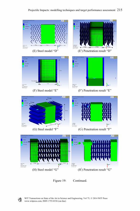
(E) Steel model “D” (Eʹ) Penetration result “D”
(F) Steel model “E” (Fʹ) Penetration result “E”
(G) Steel model “F” (Gʹ) Penetration result “F”
(H) Steel model “G” (Hʹ) Penetration result “G”
Figure 19: Continued.
Projectile Impacts: modelling techniques and target performance assessment 215
www.witpress.com, ISSN 1755-8336 (on-line) WIT Transactions on State of the Art in Science and Engineering, Vol 75, © 2014 WIT Press
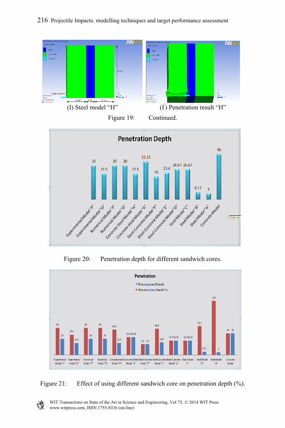
(I) Steel model “H” (Iʹ) Penetration result “H”
Figure 19: Continued.
Figure 20: Penetration depth for different sandwich cores.
Figure 21: Effect of using different sandwich core on penetration depth (%).
216 Projectile Impacts: modelling techniques and target performance assessment
www.witpress.com, ISSN 1755-8336 (on-line) WIT Transactions on State of the Art in Science and Engineering, Vol 75, © 2014 WIT Press
5 Conclusions
The main conclusions of the study can be summarized as follows. The AUTODYNE code satisfactory simulates the penetration experiments. The response of a concrete panel under penetration load can be simulated using the ANSYS finite element software package; it has the advantage of rigorous modelling and thus it has higher analysis precision, compared to that of simplified analysis.
Regarding penetration, model “D”, which is formed of two steel angle blocks and a concrete block between them is the best model according to this study as, in this case, the projectile penetration distance was found to be minimum. It was clear from the results that using steel angles instead of the equivalent steel angles as a steel block has a significant effect on the steel block for the reduction of its penetration as well as on the cost and establishment of a protective site.
The arrangement of steel angles in rows did reduce the projectile penetration distance by 20%. The sandwich panels with suppressive cores are highly recommended for use as protective structures due to the high energy dissipation by steel angles and energy absorption by concrete.
References
[1] Ekengren, B., Shelter Regulations, English edition, Swedish Rescue Services Board, Publication B54-168/94: Karlstad, Sweden, 1994.
[2] Hetherington, J.G. & Smith. P.D., Blast and Ballistic Loading of Structures, 1st ed., Butterworth-Heinemann: Oxford, UK, 1994.
[3] AUTODYN Interactive Non-Linear Dynamic Analysis software, Theory Manual, Century Dynamics Company, Inc., 2005.
Projectile Impacts: modelling techniques and target performance assessment 217
www.witpress.com, ISSN 1755-8336 (on-line) WIT Transactions on State of the Art in Science and Engineering, Vol 75, © 2014 WIT Press


