Blais Spray Applied Pipe Liners - Ohio Department of ... · Objective of the Calculations – Liner...
26
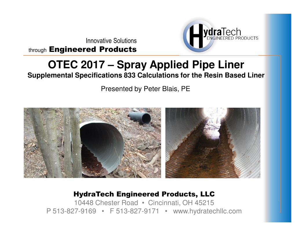
Innovative Solutions through Engineered Products HydraTech Engineered Products, LLC 10448 Chester Road • Cincinnati, OH 45215 P 513-827-9169 • F 513-827-9171 • www.hydratechllc.com Presented by Peter Blais, PE OTEC 2017 – Spray Applied Pipe Liner Supplemental Specifications 833 Calculations for the Resin Based Liner
Transcript of Blais Spray Applied Pipe Liners - Ohio Department of ... · Objective of the Calculations – Liner...
Innovative Solutions
through Engineered Products
HydraTech Engineered Products, LLC
10448 Chester Road • Cincinnati, OH 45215
P 513-827-9169 • F 513-827-9171 • www.hydratechllc.com
Presented by Peter Blais, PE
OTEC 2017 – Spray Applied Pipe LinerSupplemental Specifications 833 Calculations for the Resin Based Liner
OTEC 2017 – Spray Applied Pipe Liner
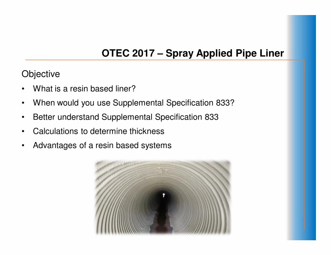
Objective
• What is a resin based liner?
• When would you use Supplemental Specification 833?
• Better understand Supplemental Specification 833
• Calculations to determine thickness
• Advantages of a resin based systems

Conduit Renewal - Resin Based Lining
What is a resin based liner?
• A two component polymer based liner, non-permeable spray
applied system.
• 100% solids (Zero VOC)
• Snap cure ~ 5 seconds
• Applied from .02” to 2.0” Thick
OTEC 2017 – Spray Applied Pipe Liner

External Repair
11Equipment/Footprint
OTEC 2017 – Spray Applied Pipe Liner
External Repair
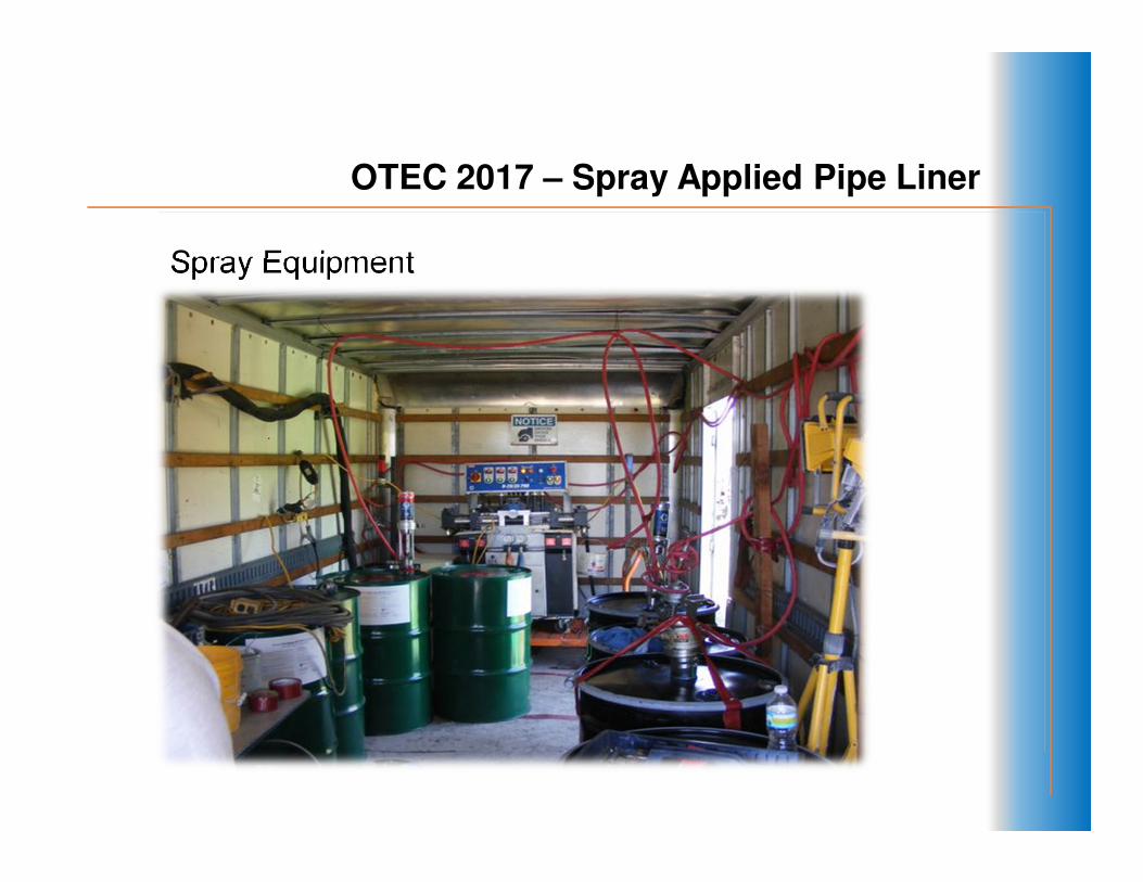
Spray Equipment
OTEC 2017 – Spray Applied Pipe Liner

Application
OTEC 2017 – Spray Applied Pipe Liner
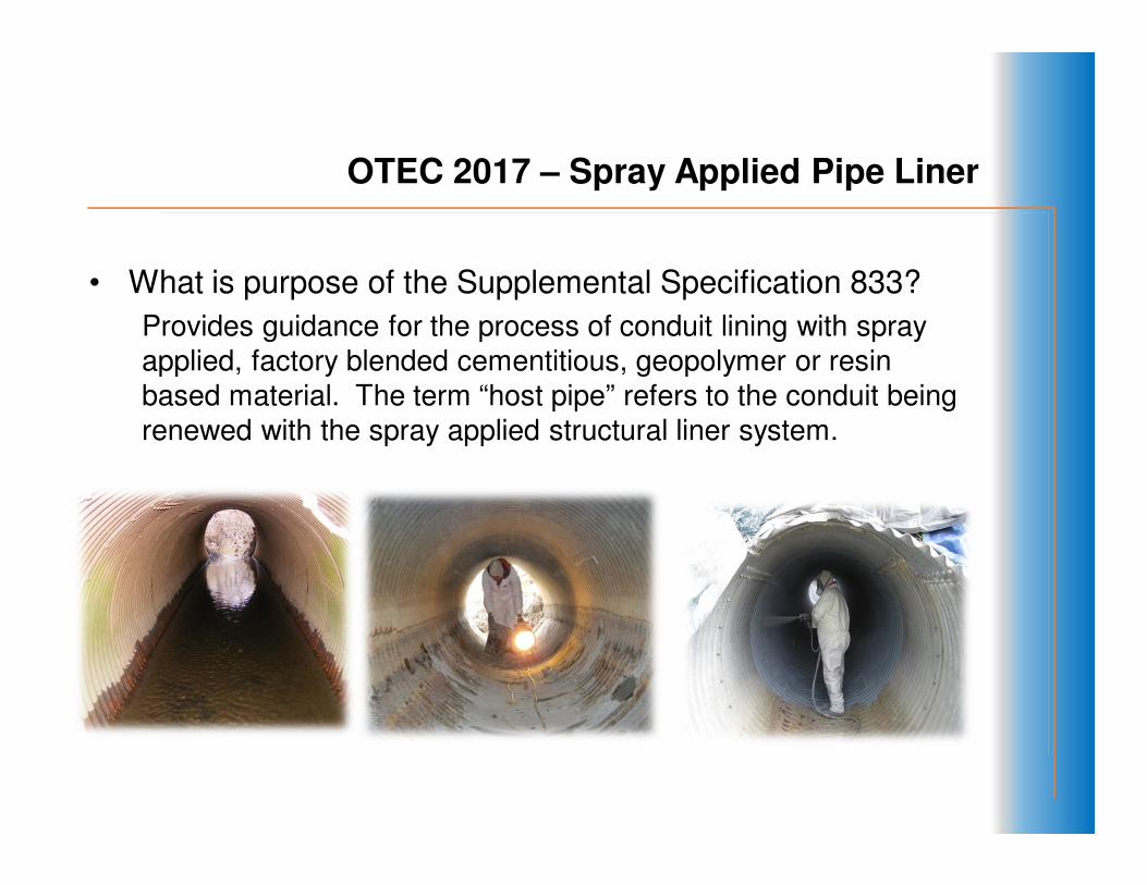
• What is purpose of the Supplemental Specification 833?
Provides guidance for the process of conduit lining with spray
applied, factory blended cementitious, geopolymer or resin
based material. The term “host pipe” refers to the conduit being
renewed with the spray applied structural liner system.
OTEC 2017 – Spray Applied Pipe Liner
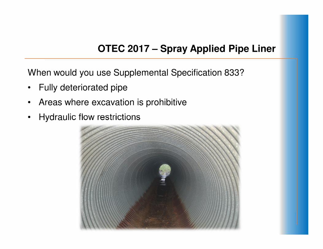
When would you use Supplemental Specification 833?
• Fully deteriorated pipe
• Areas where excavation is prohibitive
• Hydraulic flow restrictions
OTEC 2017 – Spray Applied Pipe Liner

OTEC 2017 – Spray Applied Pipe Liner
Overview of what is involved with a ODOT culvert rehabilitation project per SS833.
• Provide calculations for liner thickness
• Methods of cleaning host pipe
• Bypass flow around host pipe
• Verify thickness during installation
• Video survey of host pipe before installation
• Health and safety plan
• Letter from manufacture that the contractor is an approved installer

OTEC 2017 – Spray Applied Pipe Liner
Objective of the Calculations – Liner Thickness
How is that performed?
• Thickness is determined using the fully deteriorated appendixes gravity pipe designed for cured in place pipe (CIPP). American Society of Testing Materials (ASTM) F1216.

OTEC 2017 – Spray Applied Pipe Liner
ASTM F1216
Basis of the calculations
• Linear Calculation design appendix is based on the free-
ring structural buckling theory
• Combination of two external pressures
• Hydrostatic pressure loads at the top of the pipe unless
conditions indicate higher
• Water table
• Earth and traffic loads
• Soil density of 120 lb/cf
• Live loading is HL-93 vehicle
• Height of ground cover
OTEC 2017 – Spray Applied Pipe Liner
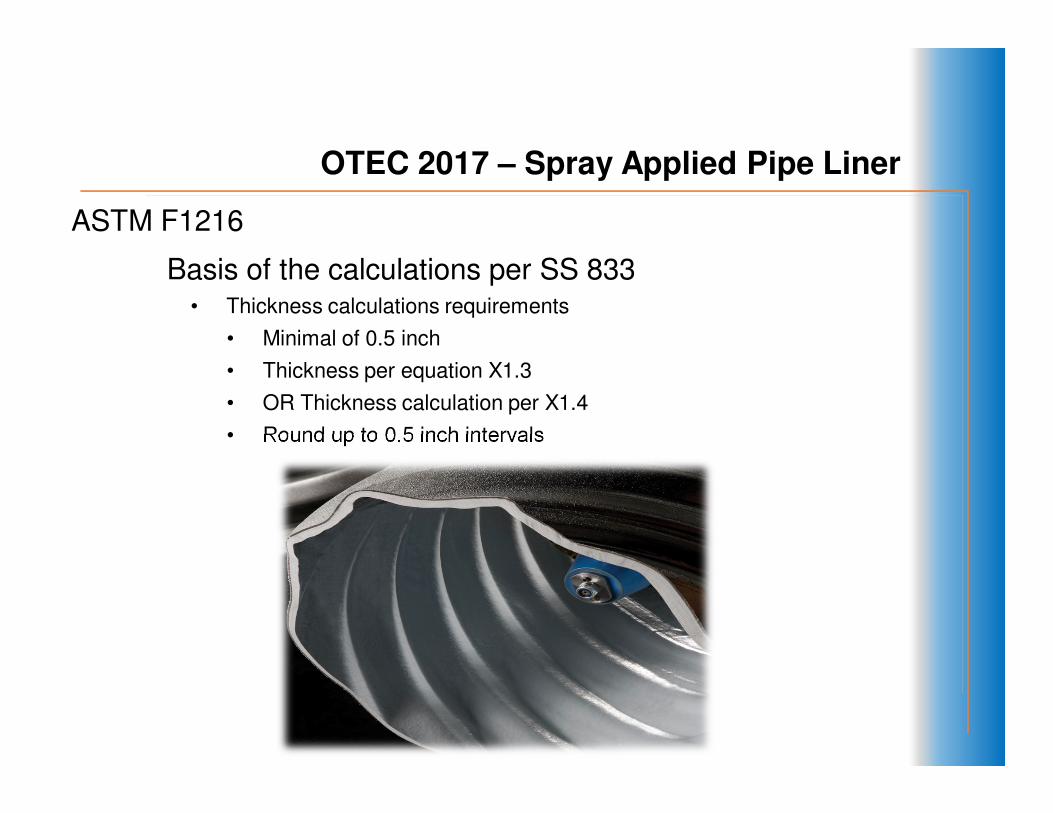
ASTM F1216
Basis of the calculations per SS 833• Thickness calculations requirements
• Minimal of 0.5 inch
• Thickness per equation X1.3
• OR Thickness calculation per X1.4
• Round up to 0.5 inch intervals
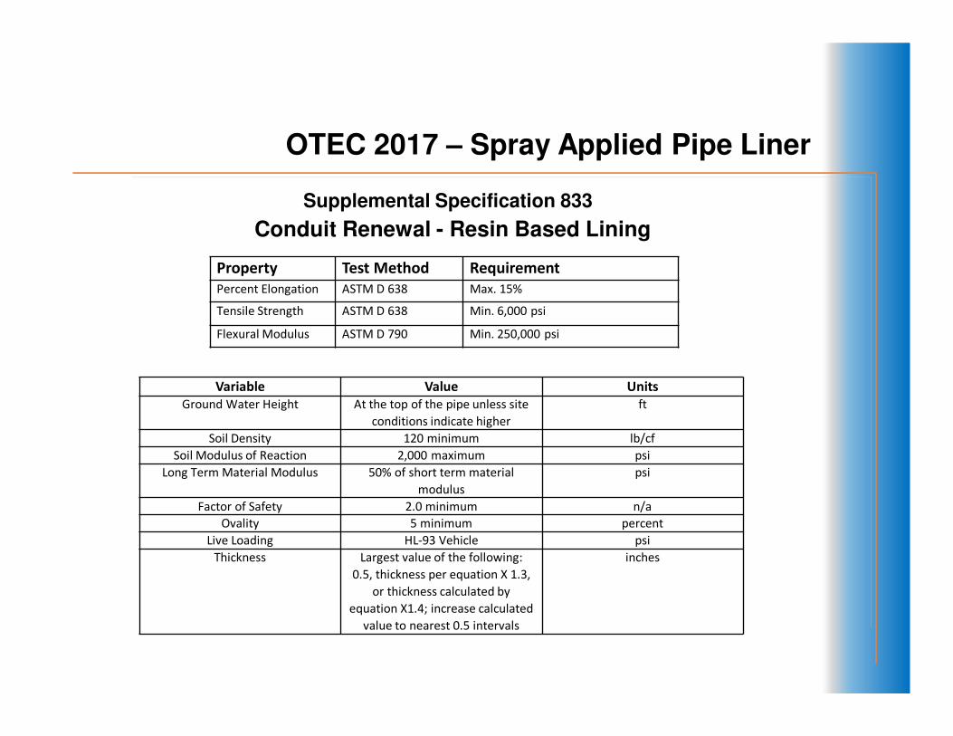
Conduit Renewal - Resin Based Lining
Property Test Method Requirement
Percent Elongation ASTM D 638 Max. 15%
Tensile Strength ASTM D 638 Min. 6,000 psi
Flexural Modulus ASTM D 790 Min. 250,000 psi
Variable Value Units
Ground Water Height At the top of the pipe unless site
conditions indicate higher
ft
Soil Density 120 minimum lb/cf
Soil Modulus of Reaction 2,000 maximum psi
Long Term Material Modulus 50% of short term material
modulus
psi
Factor of Safety 2.0 minimum n/a
Ovality 5 minimum percent
Live Loading HL-93 Vehicle psi
Thickness Largest value of the following:
0.5, thickness per equation X 1.3,
or thickness calculated by
equation X1.4; increase calculated
value to nearest 0.5 intervals
inches
Supplemental Specification 833
OTEC 2017 – Spray Applied Pipe Liner

ASTM F-1216-09 Appendix X1
Equation X1.3
Equation X1.3 - Determine all external loads on pipe
Factor for ovality
Factor for safety
Input flexural modulus of liner
Extrapolate thickness from the liners moment of inertia
OTEC 2017 – Spray Applied Pipe Liner

ASTM F-1216-09 Appendix X1
Equation X1.4
• Conservative “catch all” formula to calculate based
on pipe stiffness. The thickness is based on the
moment of inertia, flexural modulus and the inside
diameter of the liner. This calculation typically
governs over equation X1.3.
Equation X1.4
OTEC 2017 – Spray Applied Pipe Liner
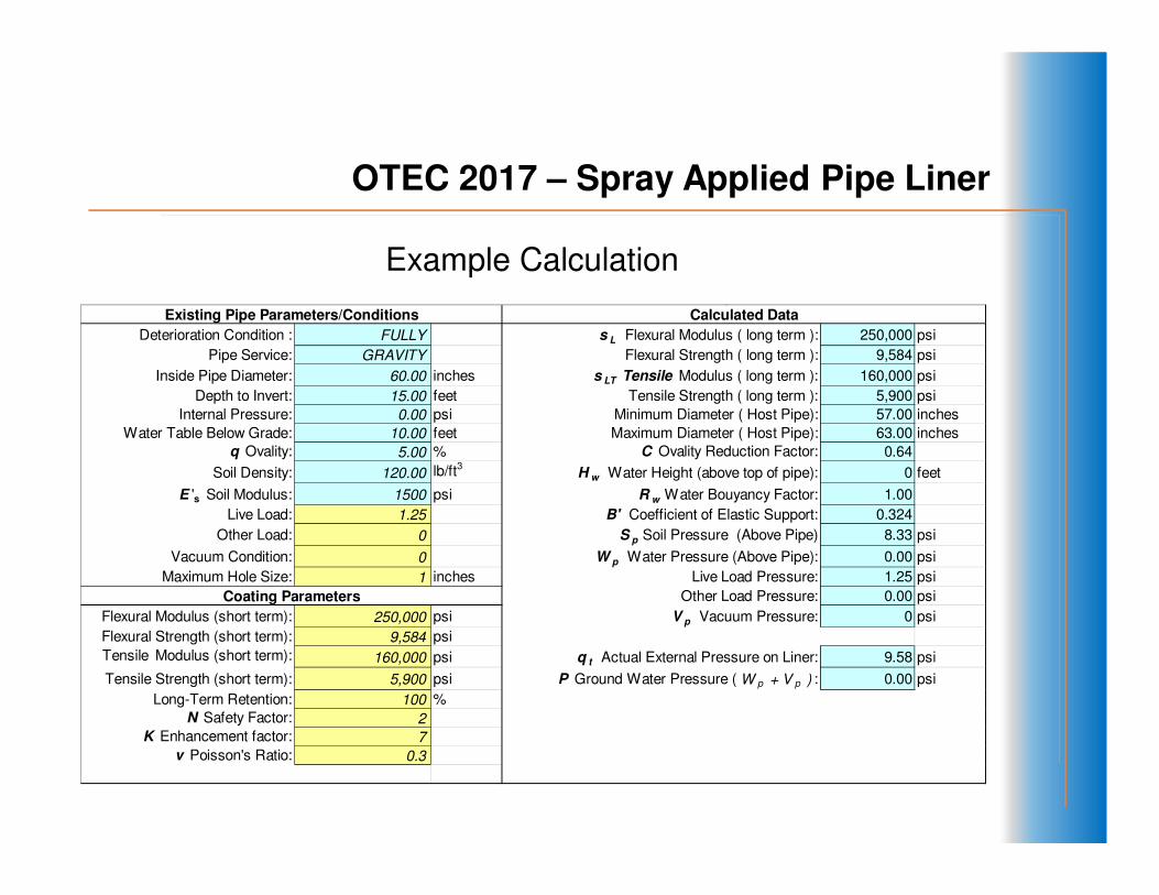
Example Calculation
OTEC 2017 – Spray Applied Pipe Liner
Deterioration Condition : FULLY s L Flexural Modulus ( long term ): 250,000 psi
Pipe Service: GRAVITY Flexural Strength ( long term ): 9,584 psi
Inside Pipe Diameter: 60.00 inches s LT Tensile Modulus ( long term ): 160,000 psi
Depth to Invert: 15.00 feet Tensile Strength ( long term ): 5,900 psi
Internal Pressure: 0.00 psi Minimum Diameter ( Host Pipe): 57.00 inches
Water Table Below Grade: 10.00 feet Maximum Diameter ( Host Pipe): 63.00 inches
q Ovality: 5.00 % C Ovality Reduction Factor: 0.64
Soil Density: 120.00 lb/ft3 H w Water Height (above top of pipe): 0 feet
E 's Soil Modulus: 1500 psi R w Water Bouyancy Factor: 1.00
Live Load: 1.25 B' Coefficient of Elastic Support: 0.324
Other Load: 0 S p Soil Pressure (Above Pipe) 8.33 psi
Vacuum Condition: 0 W p Water Pressure (Above Pipe): 0.00 psi
Maximum Hole Size: 1 inches Live Load Pressure: 1.25 psi
Other Load Pressure: 0.00 psi
Flexural Modulus (short term): 250,000 psi V p Vacuum Pressure: 0 psi
Flexural Strength (short term): 9,584 psi
Tensile Modulus (short term): 160,000 psi q t Actual External Pressure on Liner: 9.58 psi
Tensile Strength (short term): 5,900 psi P Ground Water Pressure ( W p + V p ) : 0.00 psi
Long-Term Retention: 100 %
N Safety Factor: 2
K Enhancement factor: 7
v Poisson's Ratio: 0.3
Coating Parameters
Existing Pipe Parameters/Conditions Calculated Data

Example Calculation
OTEC 2017 – Spray Applied Pipe Liner
ASTM F1216-09 Appendix X1 Equations for Establishing Minimum Thickness
in Gravity Pipe ( Equations X1.1 thru X1.4)
Partial Deteriorated Pipe SDR t ( in.) t ( mm) t min (in.)
Eq (X1.1): Hydraulic Loads due to Groundwater
P=Actual Groundwater Pressure ( W p +V p )
Eq (X1.2): Minimum Thickness if Pipe is Oval
Fully Deteriorated Pipe
Eq (X1.3): Minimum Thickness to Support Hydraulic, soil & live loads
I = t 3 /12 ; SDR=D/(( 12*(I ))^.333)
Eq (X1.4): Minimum Thickness
EI /D3 = E / 12(SDR)
3
0.195
0.99
82.6 0.726 18.452
60.48 0.992 25.197
7797.4 0.008
0.056 1.421072.5( ) ( ) N
C
DRv
KEP
L .
1
1 .
1
2
32−−
=
DRDRPN
L
1001 5.0 -
2
1001 5.1
∆+
∆+
100
∆=
σ
2/1
3
L
.
EC.''32
N
1
=
D
IEBRq swr
093.0 3
≥D
EI

OTEC 2017 – Spray Applied Pipe Liner
Resin liners versus Cementitious/Geopolymer per SS833
• Flexural modulus is the key design factor in resin based linings. Typical
of liners of plastic.
• Cementitious liners are not calculated in this manner, since the flexural
modulus of elasticity is low while the modulus of elasticity in compression
is high.
• Corrugated metal pipe is a “flexible” conduit, therefore resin based
systems have a high degree of elongation versus cementitious to
accommodate movement.
• Resin based liners have a minimal of 0.5 inch. Cementitious have a
minimal of 1.5 inch.

OTEC 2017 – Spray Applied Pipe Liner
What projects are best with a resin based liner based on SS 833?
• Corrugated metal pipe
• Round piping*
• Most economical for diameters from 42” to 72”
*Note: Arches or flat bottom pipe cannot be utilized with linear calculations

OTEC 2017 – Spray Applied Pipe Liner
ODOT 12 Project 130617 - PID 95137
Fully deteriorated condition
72” RCP pipe
Structural
Resin based lining
Case Study

OTEC 2017 – Spray Applied Pipe Liner
Project layout
Interstate 480 Mile Marker 20
Access manhole on west bound lane of highway
Case Study

OTEC 2017 – Spray Applied Pipe Liner
Initial inspection
Deterioration of the concrete (spalling)
Minor water infiltration (must be eliminated before applying liner)
Case Study

OTEC 2017 – Spray Applied Pipe Liner
Application of the resin based lining
Remote operation
Rotating guns applied the resin process
Applied at 75-100 mils per pass.
Case Study

OTEC 2017 – Spray Applied Pipe Liner
Lining system is designed to withstand the live and static loads while maintaining ground stability.
Case Study

OTEC 2017 – Spray Applied Pipe Liner
Summary
• Resin based linings are non-permeable and have a good relationship with flexible conduit.
• Supplemental specification 833 provides guidance for material requirements and liner thickness.
• Resin liners differ from cementitious liners in that ASTM F1216 calculations are required.
• Liner thicknesses are determined with linear calculations used only for circular pipe.
• Little to no restriction to inlet flow and hydraulic flow.
• Best utilized for diameters 42” - 72”
• Long term repair
OTEC 2017 – Spray Applied Pipe Liner
10448 Chester Rd.
Cincinnati, OH 45215
(513)827-9169
www.hydratechllc.com