BL Engine Kia Sorento
192
1 Contents ▣ ▣ Engine General Engine General - - Diesel Engine Basic Diesel Engine Basic - - A A - - 2.5TCI Common Rail Direct Injection 2.5TCI Common Rail Direct Injection - - Sigma Sigma - - 3.5 3.5 - - Sirius Sirius Ⅱ Ⅱ - - 2.4 2.4
Transcript of BL Engine Kia Sorento
1Contents
Engine GeneralEngine General-- Diesel Engine BasicDiesel Engine Basic
-- AA--2.5TCI Common Rail Direct Injection2.5TCI Common Rail Direct Injection
-- Sigma Sigma -- 3.53.5
-- Sirius Sirius ⅡⅡ -- 2.42.4
2Diesel Engine System
Diesel Engine
3Diesel Fuel Property
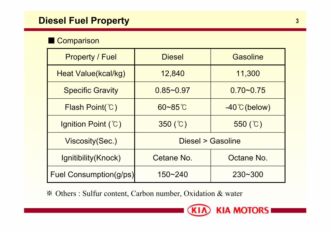
0.70~0.750.85~0.97Specific Gravity
-40(below)60~85Flash Point()
230~300150~240Fuel Consumption(g/ps)
Octane No.Cetane No.Ignitibility(Knock)
Diesel > GasolineViscosity(Sec.)
550 ()350 ()Ignition Point ()
11,30012,840Heat Value(kcal/kg)
GasolineDieselProperty / Fuel
Comparison
※ Others : Sulfur content, Carbon number, Oxidation & water
4Cetane Number
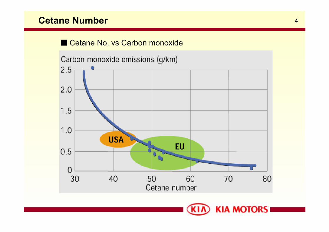
Cetane No. vs Carbon monoxide
5Diesel Fuel Property
Diesel fuel’s injection condition
1. Atomization :- The atomized mist pressurized by high pressure (nearly 100 ~ 1500bar) pump
is injected through small nozzle hole at the end of injector. This fuel mist has
collisions with compressed air in the combustion chamber with high speed.
The size of this injected mist needs to be atomized as smaller as possible so that its
total surface contacted with air becomes larger. In this reason, the atomization is the
most important factor for ignition and perfect combustion.
2. Penetration :- Even though the injected fuel is in good condition in atomization, it is difficult to meet
fresh air in compressed combustion chamber if this mist hasn’t enough power to go
fast and quite a way off. Generally Atomization and Penetration can not be met
together in normal situation since atomized mist has much more resistor for air.
6Diesel Fuel Property
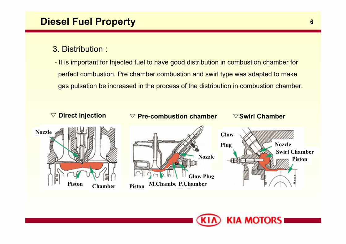
3. Distribution :- It is important for Injected fuel to have good distribution in combustion chamber for
perfect combustion. Pre chamber combustion and swirl type was adapted to make
gas pulsation be increased in the process of the distribution in combustion chamber.
Direct Injection Pre-combustion chamber Swirl Chamber
Piston
Piston
Glow Plug
Chamber
Nozzle
Piston
Glow
Plug
NozzleSwirl ChamberNozzle
M.ChamberP.Chamber
7
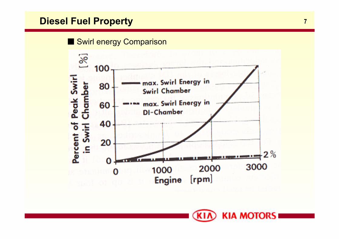
Swirl energy Comparison
Diesel Fuel Property
8
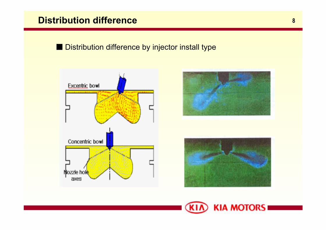
Distribution difference by injector install type
Distribution difference
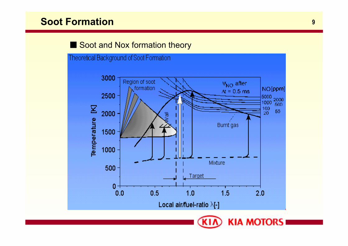
9Soot Formation
Soot and Nox formation theory
10Diesel Combustion Process
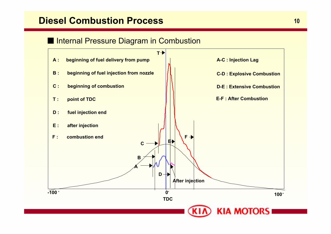
Internal Pressure Diagram in Combustion
A-C : Injection Lag
C-D : Explosive Combustion
D-E : Extensive Combustion
A : beginning of fuel delivery from pump
B : beginning of fuel injection from nozzle
C : beginning of combustion
T : point of TDC
D : fuel injection end
E : after injection
T
100˚
A
B
C
D
E
TDC-100 ˚ 0˚
After injection
E-F : After Combustion
FF : combustion end
11Diesel System Advantage and Disadvantage
Ignition Lag :
- Diesel combustion process is a little different by several reasons compared
to Gasoline’s. The ignition in diesel happens in several points by heated air when
atomized fuel mist is injected. In that reason, the fire deflection is affected by
several things such as combustion pressure, fuel temperature, water coolant
temperature, rpm and so on. The ignition lag in internal pressure diagram
shows the connection among the mentioned items before. Generally in diesel
engine this lag becomes about 3~ 7ms, but it’s different by conditions.
If Ignition lag becomes longer, the detonation, diesel knock easily happens.
The way to shorten this lag is :
- Using High compression rate - High Centan No. fuel
- Retard the injection time - Using swirl to increase deflection speed
- Turbocharger with intercooler - Small nozzle size
- appropriate working temperature in fuel, water coolant and air intake
12
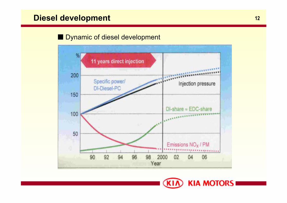
Dynamic of diesel development
Diesel development
13Diesel System Advantage and Disadvantage
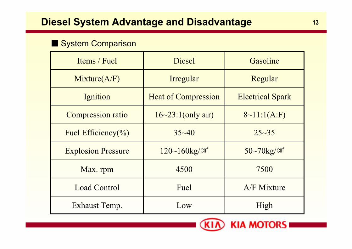
System Comparison
50~70kg/120~160kg/Explosion Pressure
8~11:1(A:F)16~23:1(only air)Compression ratio
Electrical SparkHeat of Compression Ignition
25~3535~40Fuel Efficiency(%)
HighLowExhaust Temp.
A/F MixtureFuelLoad Control
75004500Max. rpm
RegularIrregularMixture(A/F)
GasolineDieselItems / Fuel
14Diesel System Advantage and Disadvantage
Advantage- Using cheaper fuel (Generally)
- Using the heat of compression to ignite ⇒ It makes system simple.
- High efficiency at light loads and idle speeds
- High compression ratio⇒ good fuel consumption
- Fuel efficiency is higher (by 15%)
- Components’ durability
Disadvantage
- Precise in injection system and durability⇒ these make them more
expensive to build
- Output torque range is shorter than gasoline’s
- Harmful emission gas ⇒ soot-laden(particles), sulfur content,
- Detonation is easy to occur
15Stroke Cycle Comparison
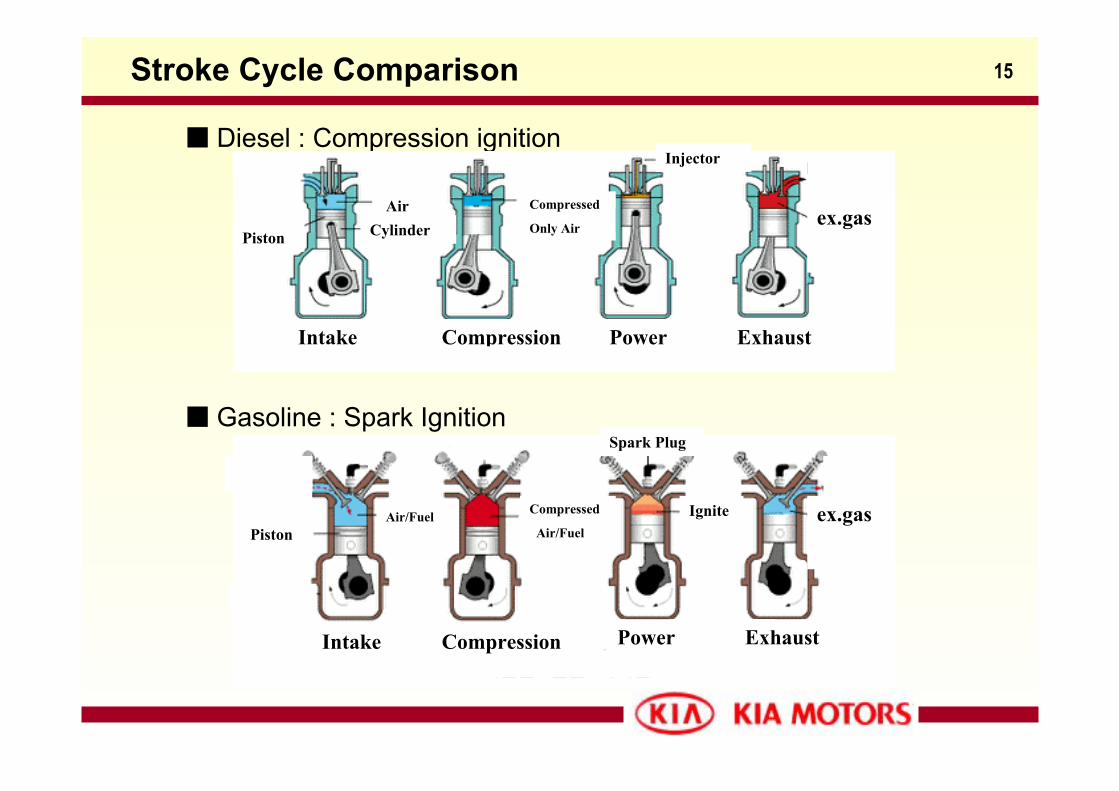
Diesel : Compression ignition
Gasoline : Spark Ignition
ex.gas
Intake Compression Power Exhaust
Cylinder
Compressed
Only Air
Injector
Air
Piston
ex.gas
Intake Compression
Compressed
Air/Fuel
Spark Plug
IgnitePiston
Air/Fuel
Power Exhaust
16Group discussion
Subject : Common Rail System
1. Discuss by party what the common rail system is
- Concept, main components, the difference verse IDI system,
- Your country’s situation in commercial diesel vehicle
- Advantage or disadvantage etc.
2. Present each party’s output
- Use 5 minutes for presentation
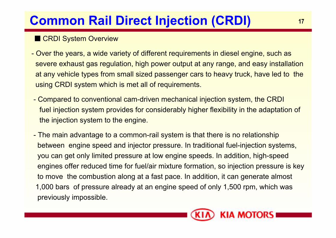
17Common Rail Direct Injection (CRDI)
- Over the years, a wide variety of different requirements in diesel engine, such as severe exhaust gas regulation, high power output at any range, and easy installationat any vehicle types from small sized passenger cars to heavy truck, have led to the using CRDI system which is met all of requirements.
- Compared to conventional cam-driven mechanical injection system, the CRDIfuel injection system provides for considerably higher flexibility in the adaptation of the injection system to the engine.
- The main advantage to a common-rail system is that there is no relationshipbetween engine speed and injector pressure. In traditional fuel-injection systems,you can get only limited pressure at low engine speeds. In addition, high-speedengines offer reduced time for fuel/air mixture formation, so injection pressure is keyto move the combustion along at a fast pace. In addition, it can generate almost1,000 bars of pressure already at an engine speed of only 1,500 rpm, which waspreviously impossible.
CRDI System Overview
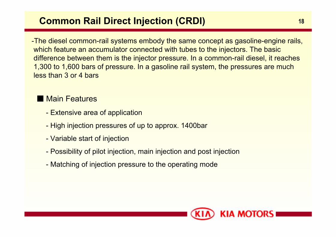
18Common Rail Direct Injection (CRDI)
-The diesel common-rail systems embody the same concept as gasoline-engine rails,which feature an accumulator connected with tubes to the injectors. The basicdifference between them is the injector pressure. In a common-rail diesel, it reaches1,300 to 1,600 bars of pressure. In a gasoline rail system, the pressures are muchless than 3 or 4 bars
- Extensive area of application
- High injection pressures of up to approx. 1400bar
- Variable start of injection
- Possibility of pilot injection, main injection and post injection
- Matching of injection pressure to the operating mode
Main Features
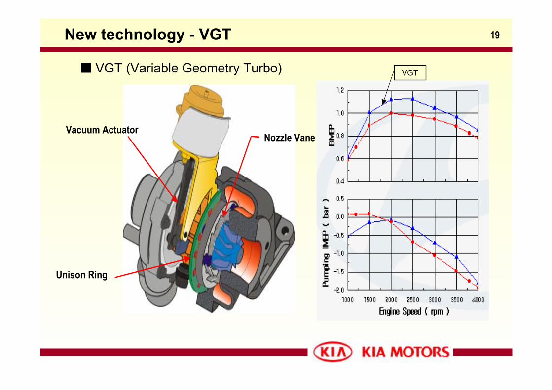
19
Nozzle VaneVacuum Actuator
Unison Ring
New technology - VGT
VGT (Variable Geometry Turbo) VGT
20
A-2.5 TCI Mechanical system
A-2.5 TCI (CDRI)
21A-2.5 TCI CRDI Eng.
A-2.5 TCI
22A-2.5 TCI (CDRI) – High Speed Direct Injection
Increasing specific power and fuel consumption- DOHC 4 valve with swing roller arm
- Turbocharger with intercooler
- State-of-the-art Electronic Diesel Control(EDC)
by Bosch with Common Rail
- Electronically controlled high precise injectors
installed in the center of the combustion chamber
- High injection pressure up to approx. 1,350 bar
Low emission and NVH decreased
- Pilot injection prior to main injection
- Balance shafts
- EGR system with oxidation catalytic converter
- Cam carrier and ladder frame type bed plate
23
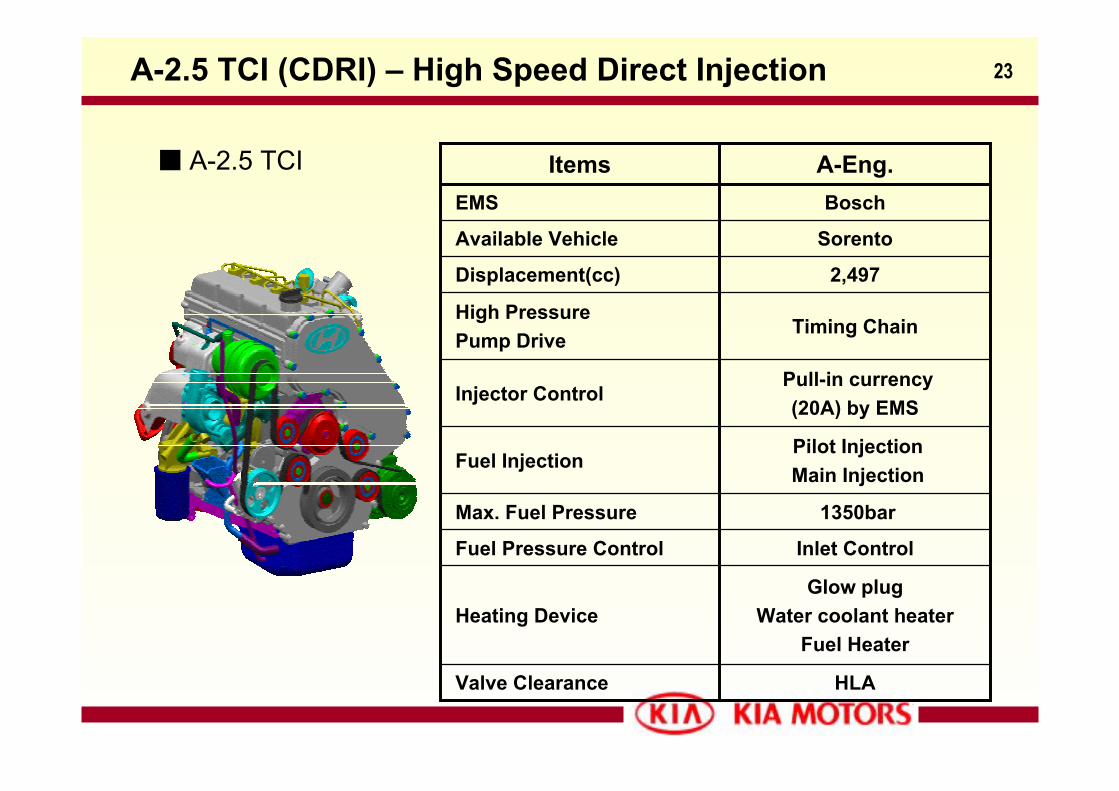
A-2.5 TCI
A-2.5 TCI (CDRI) – High Speed Direct Injection
BoschEMS
HLAValve Clearance
Glow plug Water coolant heater
Fuel HeaterHeating Device
Inlet ControlFuel Pressure Control
1350barMax. Fuel Pressure
Pilot InjectionMain Injection
Fuel Injection
Pull-in currency(20A) by EMS
Injector Control
Timing ChainHigh PressurePump Drive
2,497Displacement(cc)
SorentoAvailable Vehicle
A-Eng.Items
24
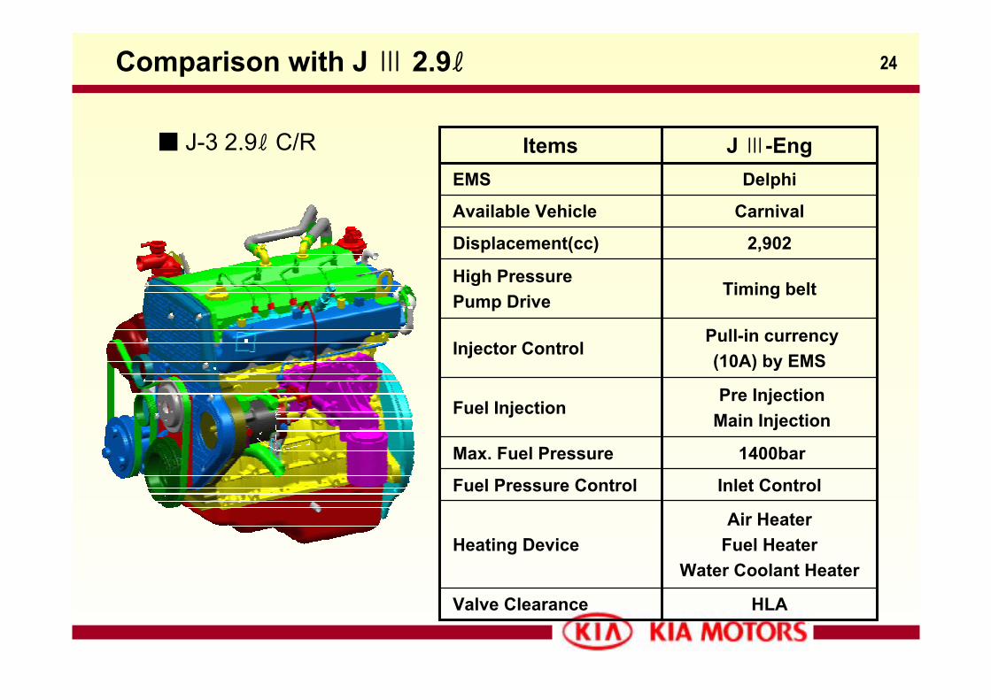
J-3 2.9ℓ C/R
Comparison with J Ⅲ 2.9ℓ
DelphiEMS
HLAValve Clearance
Air HeaterFuel Heater
Water Coolant HeaterHeating Device
Inlet ControlFuel Pressure Control
1400barMax. Fuel Pressure
Pre InjectionMain Injection
Fuel Injection
Pull-in currency(10A) by EMS
Injector Control
Timing beltHigh PressurePump Drive
2,902Displacement(cc)
CarnivalAvailable Vehicle
J Ⅲ-EngItems
25
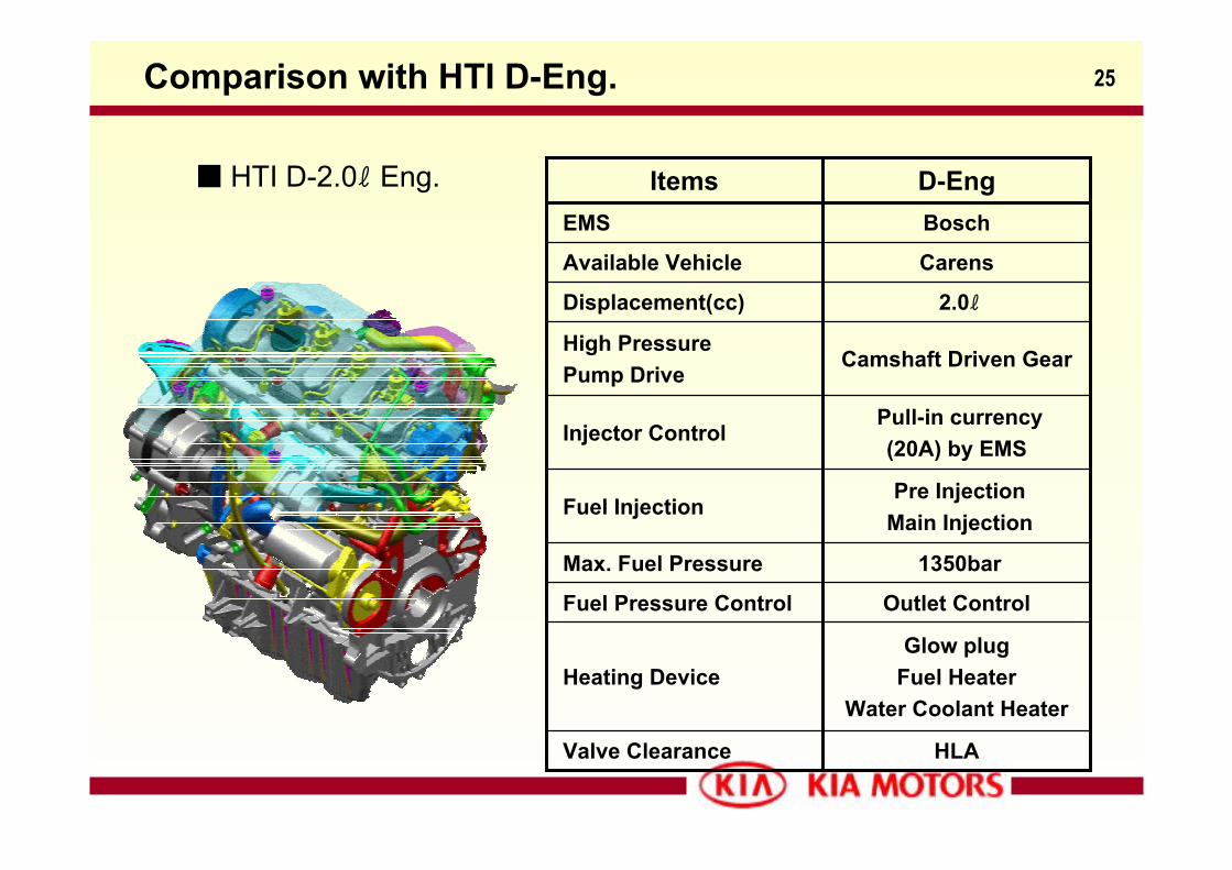
HTI D-2.0ℓ Eng.
Comparison with HTI D-Eng.
BoschEMS
HLAValve Clearance
Glow plugFuel Heater
Water Coolant HeaterHeating Device
Outlet ControlFuel Pressure Control
1350barMax. Fuel Pressure
Pre InjectionMain Injection
Fuel Injection
Pull-in currency(20A) by EMS
Injector Control
Camshaft Driven GearHigh PressurePump Drive
2.0ℓDisplacement(cc)
Carens Available Vehicle
D-EngItems
26
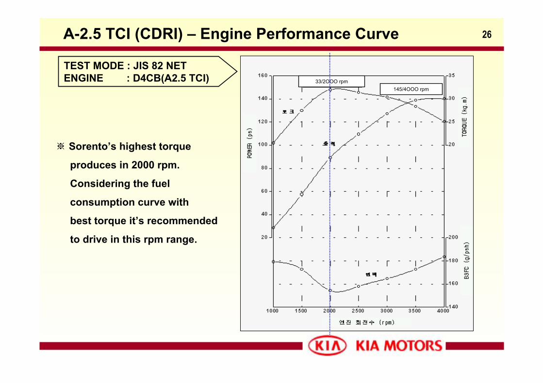
TEST MODE : JIS 82 NETENGINE : D4CB(A2.5 TCI) 33/2OOO rpm
145/4OOO rpm
A-2.5 TCI (CDRI) – Engine Performance Curve
※ Sorento’s highest torque
produces in 2000 rpm.
Considering the fuel
consumption curve with
best torque it’s recommended
to drive in this rpm range.
27
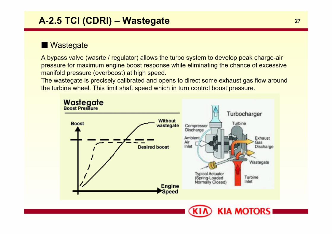
A bypass valve (wasrte / regulator) allows the turbo system to develop peak charge-air pressure for maximum engine boost response while eliminating the chance of excessive manifold pressure (overboost) at high speed. The wastegate is precisely calibrated and opens to direct some exhaust gas flow around the turbine wheel. This limit shaft speed which in turn control boost pressure.
Wastegate
A-2.5 TCI (CDRI) – Wastegate
28
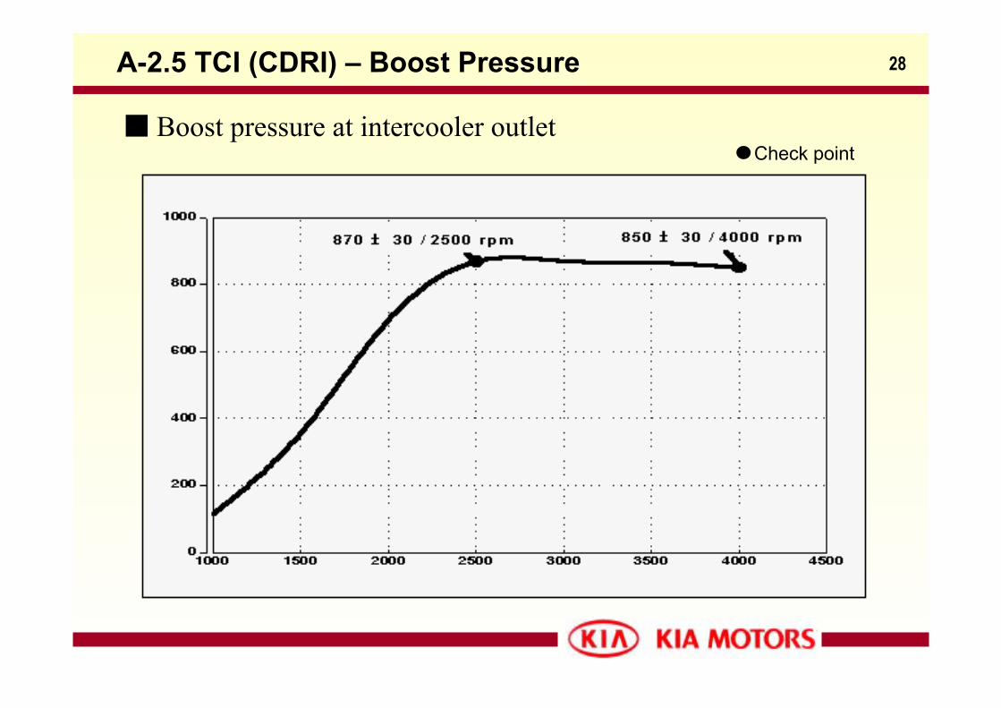
Boost pressure at intercooler outletCheck point
A-2.5 TCI (CDRI) – Boost Pressure
29
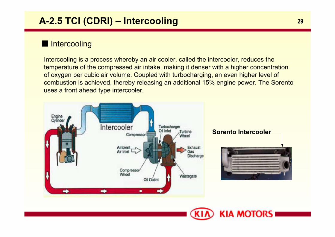
Intercooling is a process whereby an air cooler, called the intercooler, reduces the temperature of the compressed air intake, making it denser with a higher concentration of oxygen per cubic air volume. Coupled with turbocharging, an even higher level of combustion is achieved, thereby releasing an additional 15% engine power. The Sorento uses a front ahead type intercooler.
Intercooling
A-2.5 TCI (CDRI) – Intercooling
Sorento Intercooler
30
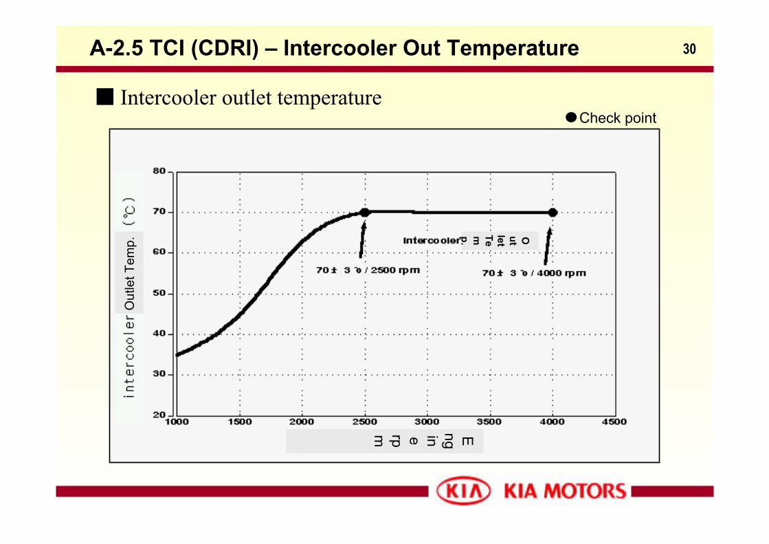
Intercooler outlet temperatureCheck point
A-2.5 TCI (CDRI) – Intercooler Out Temperature
Out
let T
emp.
Engine rpm
Outlet Temp.
31A-2.5 TCI(CRDI) - Common Rail System Layout
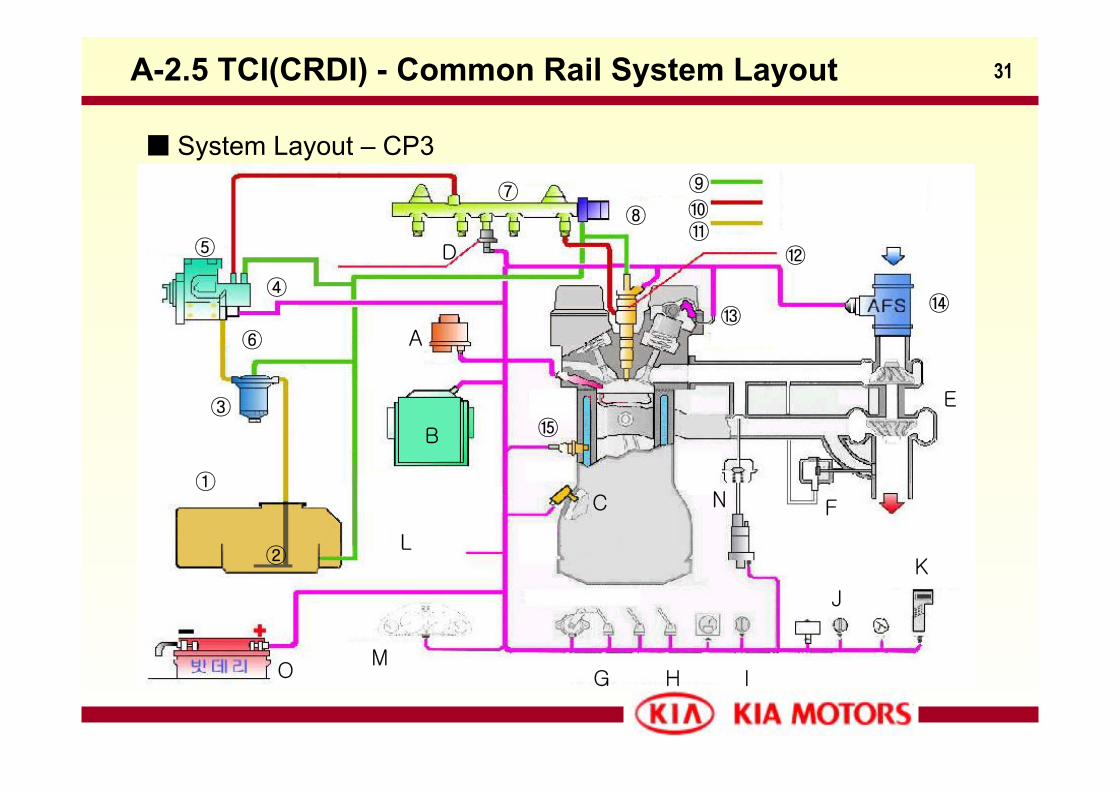
System Layout – CP3
①
M
KL
A
②
③
④
⑤
⑥
D
⑦⑧
⑨⑩⑪
⑫
⑬⑭
⑮B
C
E
F
G H I
J
O
N
32
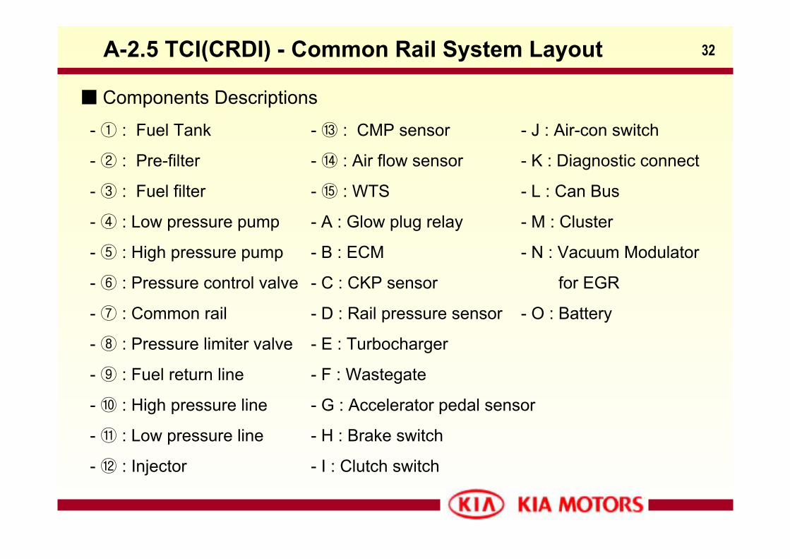
Components Descriptions
- ① : Fuel Tank
- ② : Pre-filter
- ③ : Fuel filter
- ④ : Low pressure pump
- ⑤ : High pressure pump
- ⑥ : Pressure control valve
- ⑦ : Common rail
- ⑧ : Pressure limiter valve
- ⑨ : Fuel return line
- ⑩ : High pressure line
- ⑪ : Low pressure line
- ⑫ : Injector
- ⑬ : CMP sensor
- ⑭ : Air flow sensor
- ⑮ : WTS
- A : Glow plug relay
- B : ECM
- C : CKP sensor
- D : Rail pressure sensor
- E : Turbocharger
- F : Wastegate
- G : Accelerator pedal sensor
- H : Brake switch
- I : Clutch switch
- J : Air-con switch
- K : Diagnostic connect
- L : Can Bus
- M : Cluster
- N : Vacuum Modulator
for EGR
- O : Battery
A-2.5 TCI(CRDI) - Common Rail System Layout
33
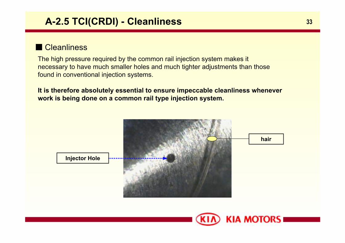
The high pressure required by the common rail injection system makes it necessary to have much smaller holes and much tighter adjustments than those found in conventional injection systems.
It is therefore absolutely essential to ensure impeccable cleanliness whenever work is being done on a common rail type injection system.
A-2.5 TCI(CRDI) - Cleanliness
Cleanliness
Injector Hole
hair
34
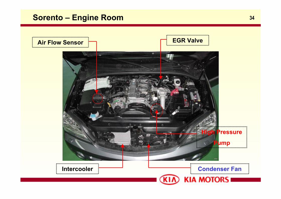
High Pressure
Pump
Condenser FanIntercooler
EGR ValveAir Flow Sensor
Sorento – Engine Room
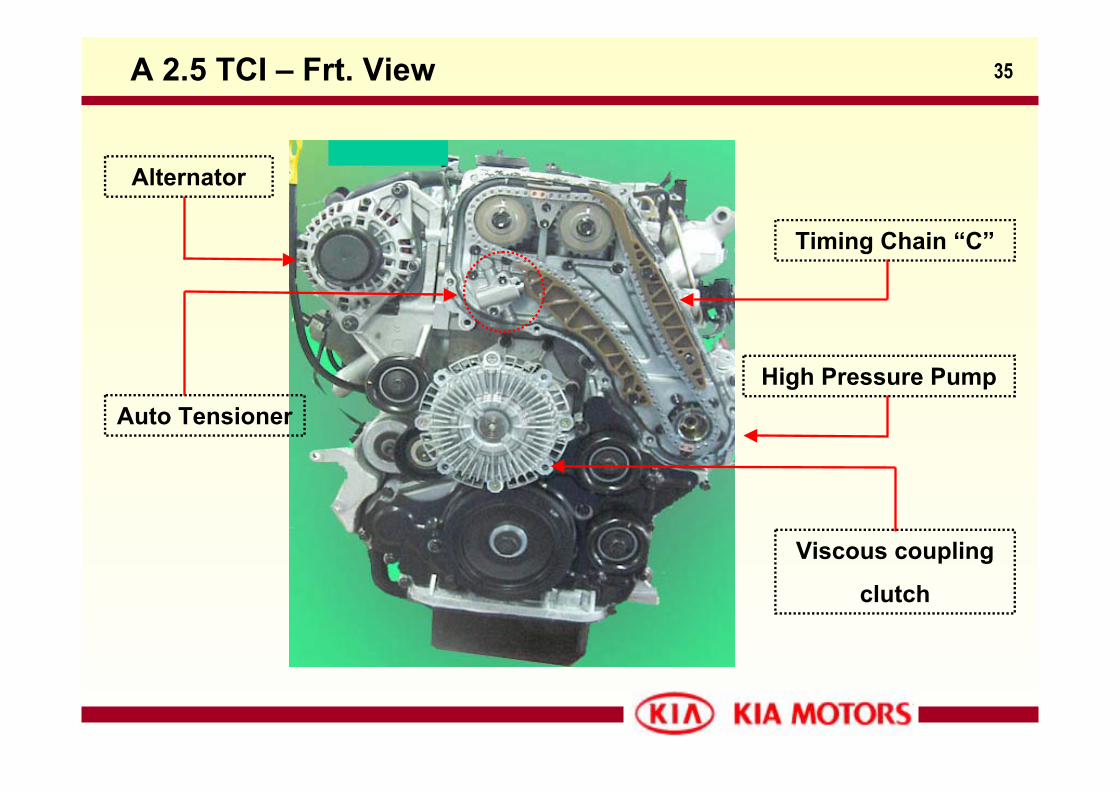
35A 2.5 TCI – Frt. View
Alternator
Auto Tensioner
Timing Chain “C”
High Pressure Pump
Viscous coupling
clutch
36
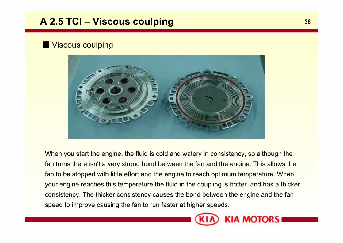
Viscous coulping
A 2.5 TCI – Viscous coulping
When you start the engine, the fluid is cold and watery in consistency, so although the fan turns there isn't a very strong bond between the fan and the engine. This allows the fan to be stopped with little effort and the engine to reach optimum temperature. When your engine reaches this temperature the fluid in the coupling is hotter and has a thickerconsistency. The thicker consistency causes the bond between the engine and the fan speed to improve causing the fan to run faster at higher speeds.
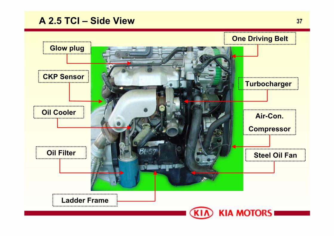
37A 2.5 TCI – Side View
Glow plug
CKP Sensor
Oil Cooler
Oil Filter
One Driving Belt
Turbocharger
Air-Con.
Compressor
Ladder Frame
Steel Oil Fan
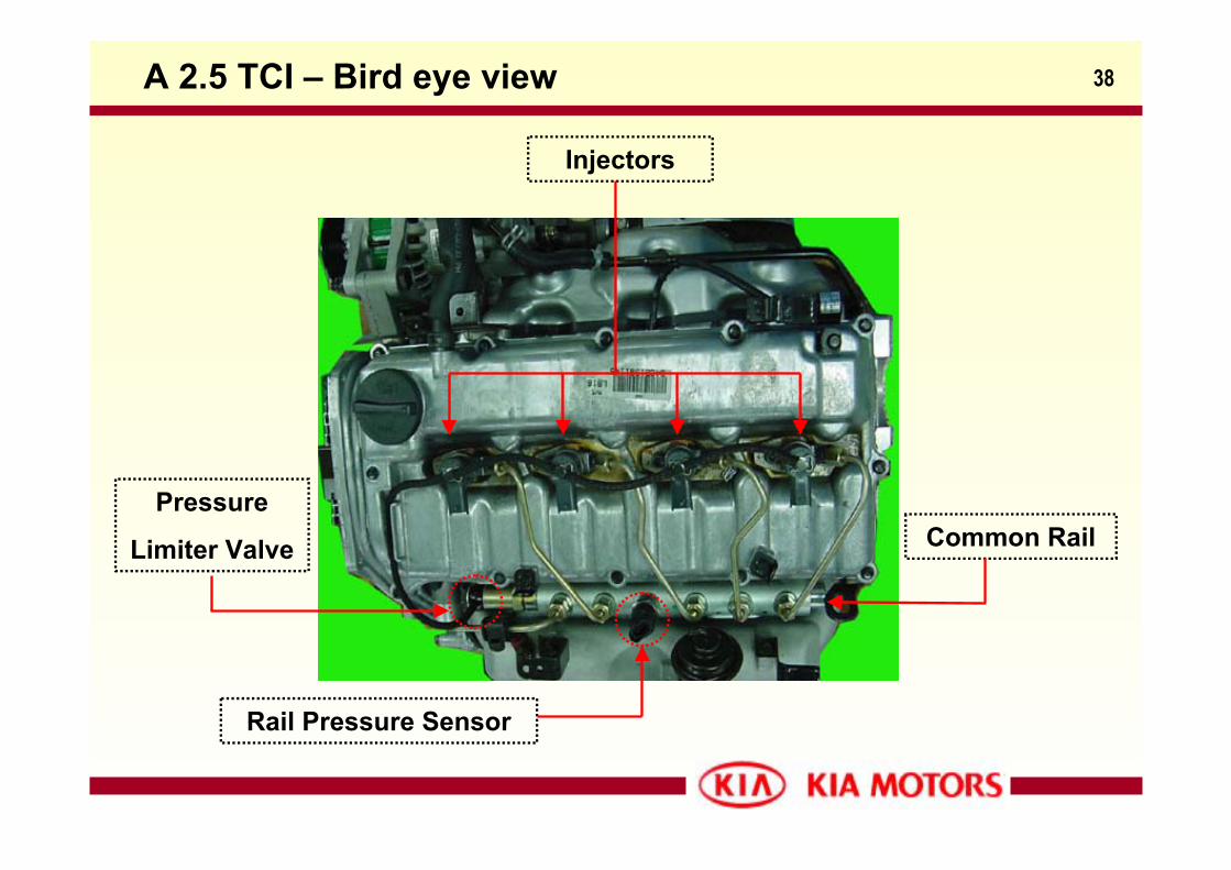
38A 2.5 TCI – Bird eye view
Injectors
Common Rail
Rail Pressure Sensor
Pressure
Limiter Valve
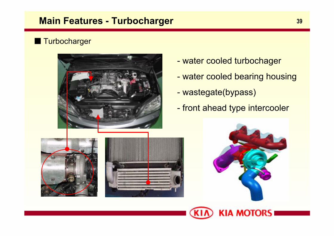
39Main Features - Turbocharger
Turbocharger
- water cooled turbochager
- water cooled bearing housing
- wastegate(bypass)
- front ahead type intercooler
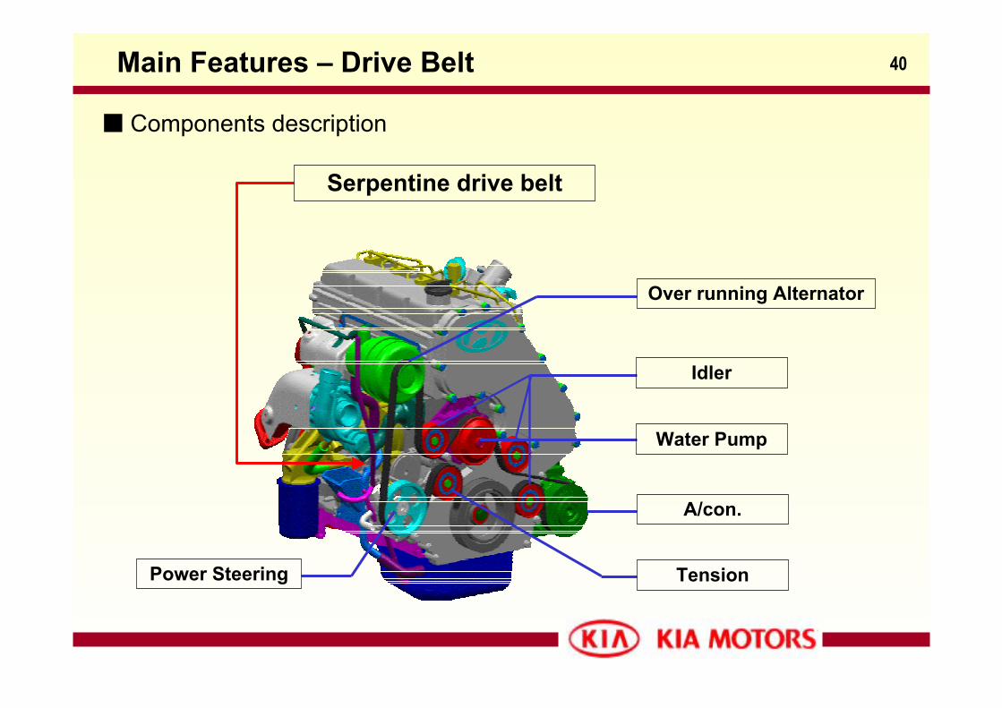
40Main Features – Drive Belt
Components description
Serpentine drive belt
Idler
Over running Alternator
A/con.
Water Pump
Tension Power Steering
41Main Features – Cam Carrier
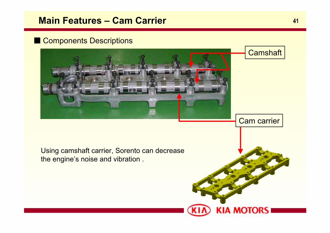
Components DescriptionsCamshaft
Cam carrier
Using camshaft carrier, Sorento can decrease the engine’s noise and vibration .
42Main Features – Valve Train & Camshaft
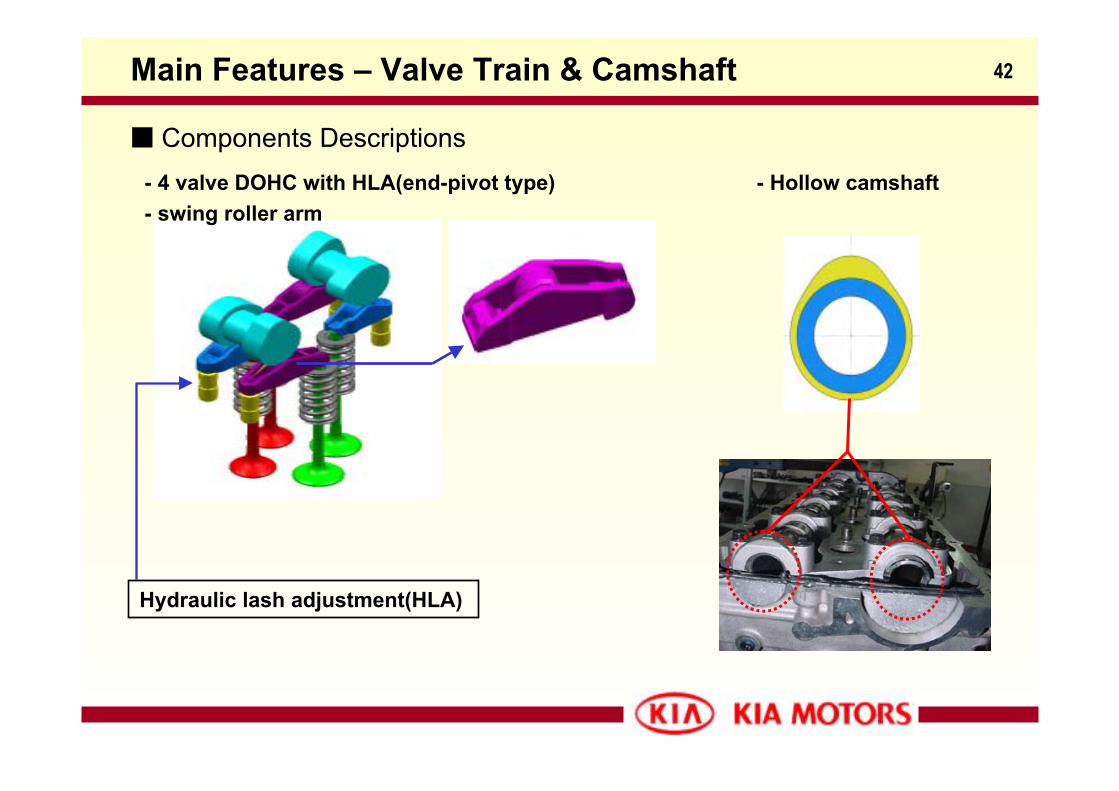
Components Descriptions- 4 valve DOHC with HLA(end-pivot type) - swing roller arm
Hydraulic lash adjustment(HLA)
- Hollow camshaft
43Main Features – Piston & Connecting Rod
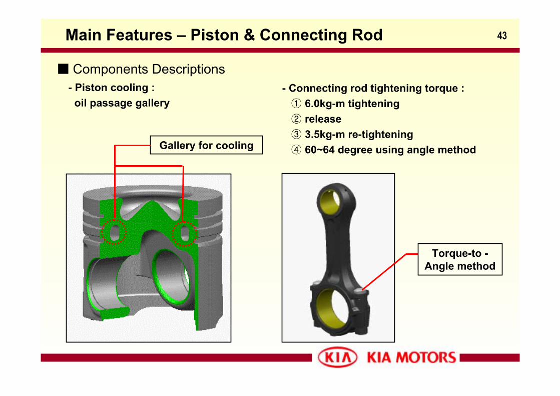
Components Descriptions- Piston cooling :
oil passage gallery
Gallery for cooling
- Connecting rod tightening torque :① 6.0kg-m tightening② release③ 3.5kg-m re-tightening④ 60~64 degree using angle method
Torque-to -Angle method
44Ref. #1-Tightening Torque Methods
- There are three types of cylinder head bolts (in some case connecting rod cap boltsincluded) tightening procedures in modern vehicle.
1) Traditional torque method2) Torque-to-yield3) Torque-to-angle
- Traditional torque method fastens each bolt to its yield point calculated by its elasticity. The one demerit of this method is not able to compensate for variations in each bolt’s thread friction. The other one is each bolt is easy to retract to its original length when the axial and torsional force is relieved by combined heatingand cooling action of the engine.
- To reduce these disadvantages mentioned before, new modern vehicles require torque-to-yield or torque-to-angle methods by need. The bolt which is tightened by both these methods stretches beyond elasticity towhat’s called the “yield point”. It stays stretched and won’t come back to its original length when loosened. Oncethis point is reached, re-torque won’t increase clamping force very much.
Tightening torque methods :
45
- In any case using both torque-to-yield and torque-to-angle each bolt is recommendednot to reuse, since you don’t know how much or how often it has been tightened in the past, regardless of the possibility of reusing a certain number of times.
- For proper installation in the torque-to-angle methods, an indicator gauge is requiredmore than one torquing sequence. This results in more accurate installation than usingonly a torque wrench and the ‘eyeball estimate’ method.
Ref. #1-Tightening Torque Methods
- Connecting rod cap bolt torquing procedure in Sorento : ① 6.0kg-m tighten※ Torque the bolts in the proper sequence
② Release③ 3.5kg-m re-tighten④ 60~64 degree of rotation (needed a torque-to-angle indicator gauge)
46Main Features – NVH
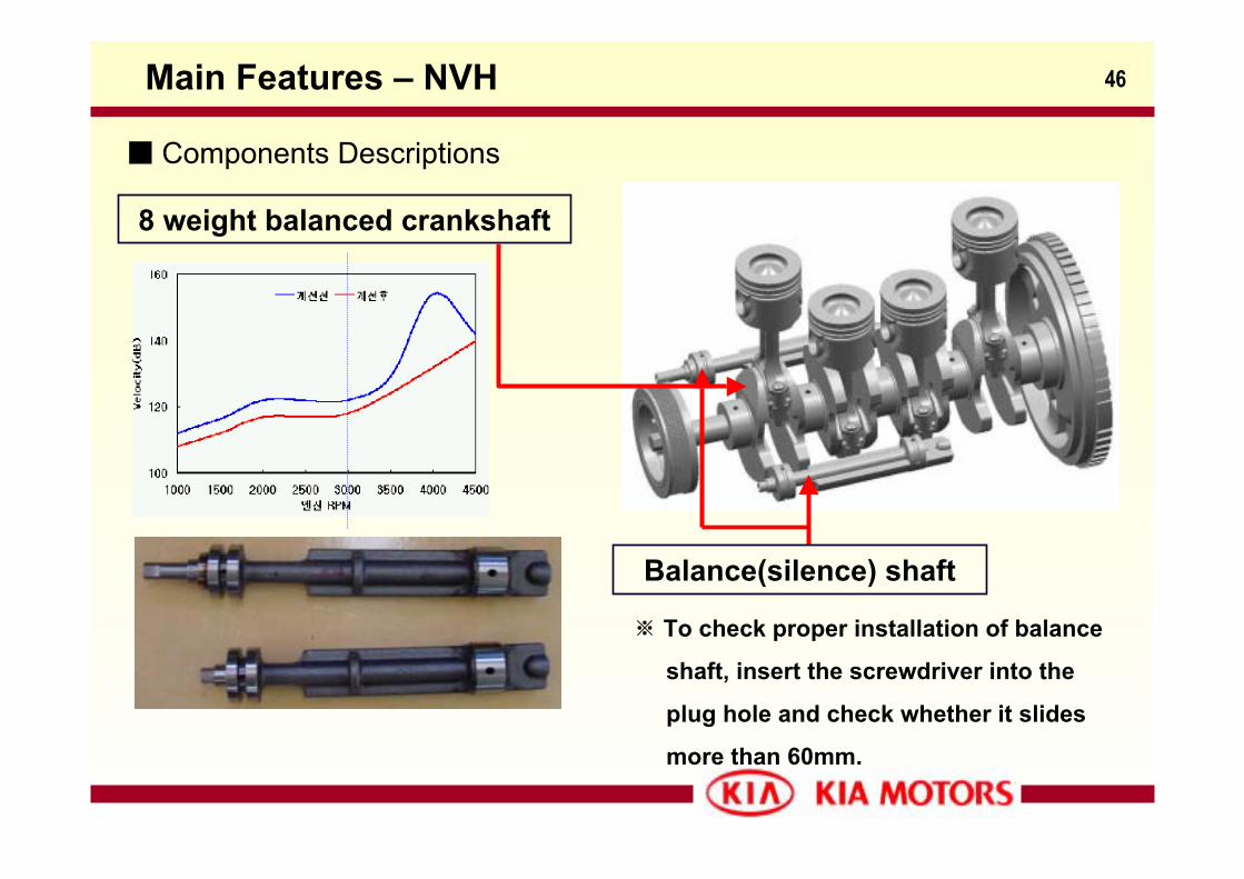
Components Descriptions
8 weight balanced crankshaft
Balance(silence) shaft
※ To check proper installation of balance
shaft, insert the screwdriver into the
plug hole and check whether it slides
more than 60mm.
47Main Features - NVH
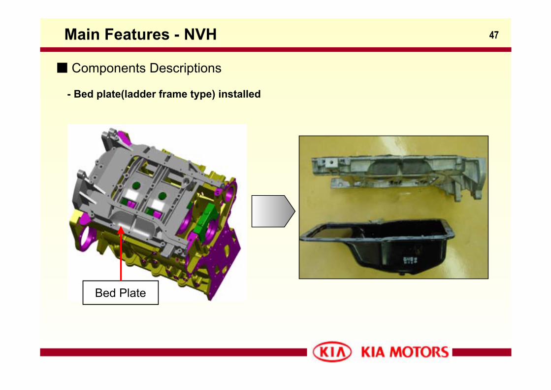
Components Descriptions
- Bed plate(ladder frame type) installed
Bed Plate
48Main Features – Oil Pump
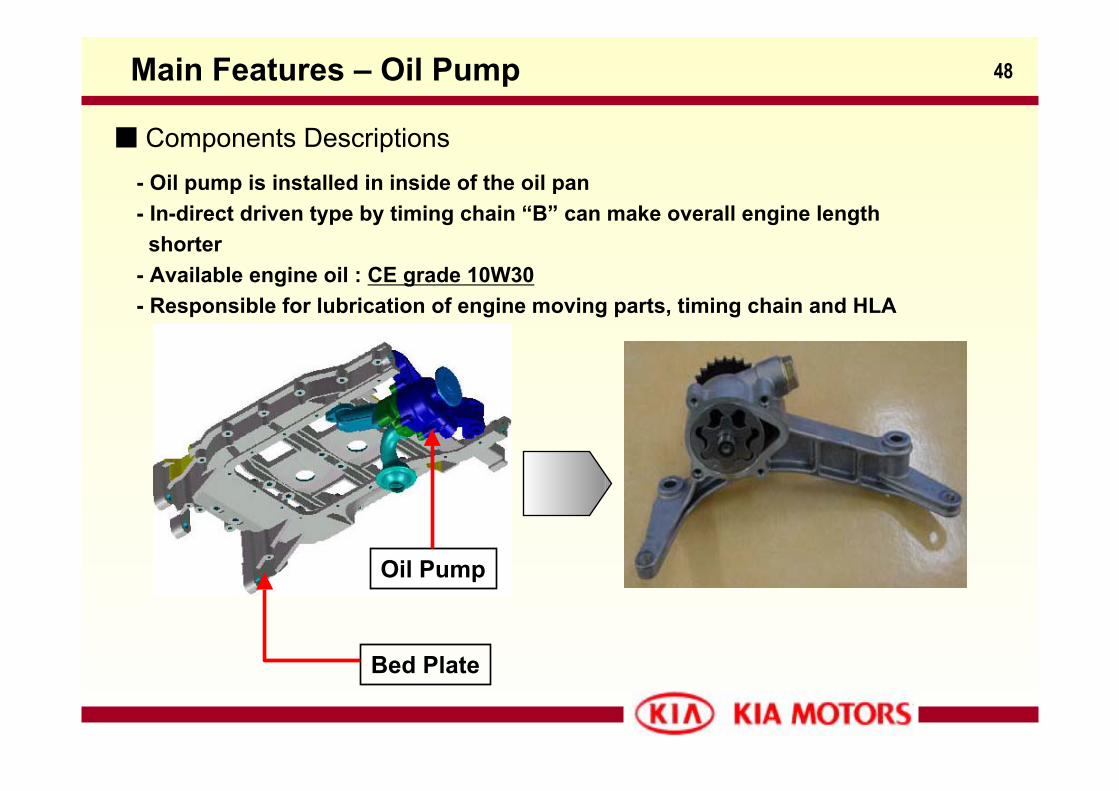
Components Descriptions- Oil pump is installed in inside of the oil pan- In-direct driven type by timing chain “B” can make overall engine length
shorter- Available engine oil : CE grade 10W30- Responsible for lubrication of engine moving parts, timing chain and HLA
Bed Plate
Oil Pump
49Timing Chain
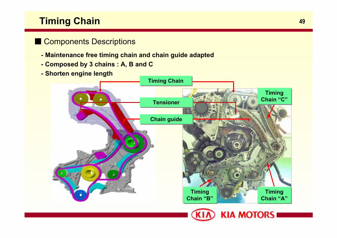
Components Descriptions- Maintenance free timing chain and chain guide adapted- Composed by 3 chains : A, B and C- Shorten engine length
Timing ChainTiming Chain
TensionerTensioner
Chain guideChain guide
Timing Chain “A”
Timing Chain “A”
Timing Chain “C”
Timing Chain “C”
Timing Chain “B”
Timing Chain “B”
50
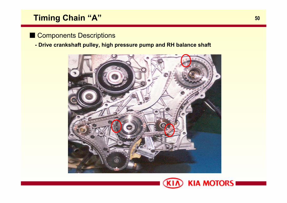
Components Descriptions
Timing Chain “A”
- Drive crankshaft pulley, high pressure pump and RH balance shaft
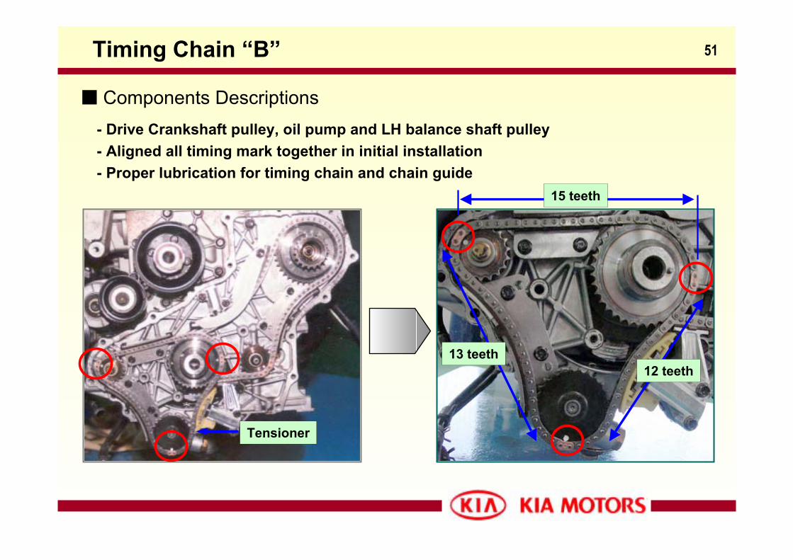
51Timing Chain “B”
Components Descriptions- Drive Crankshaft pulley, oil pump and LH balance shaft pulley- Aligned all timing mark together in initial installation- Proper lubrication for timing chain and chain guide
Tensioner
15 teeth
12 teeth13 teeth
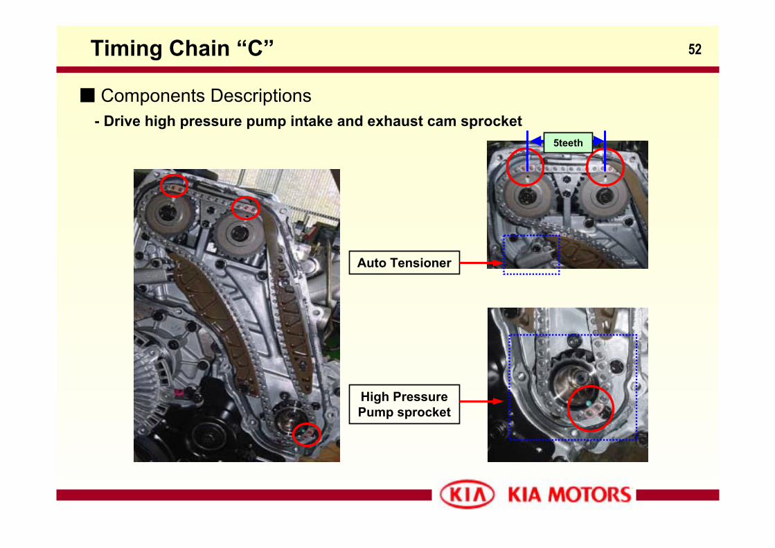
52Timing Chain “C”
Components Descriptions
5teeth
- Drive high pressure pump intake and exhaust cam sprocket
High PressurePump sprocket
Auto Tensioner
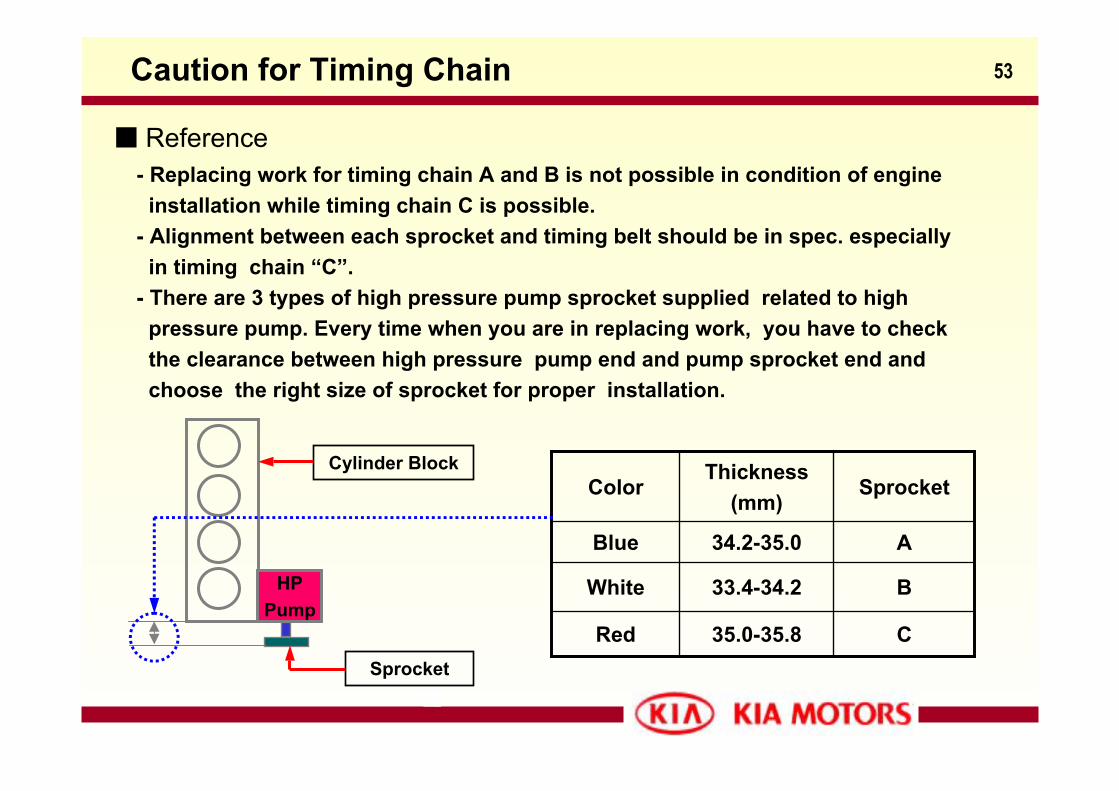
53Caution for Timing Chain
- Replacing work for timing chain A and B is not possible in condition of engineinstallation while timing chain C is possible.
- Alignment between each sprocket and timing belt should be in spec. especiallyin timing chain “C”.
- There are 3 types of high pressure pump sprocket supplied related to high pressure pump. Every time when you are in replacing work, you have to checkthe clearance between high pressure pump end and pump sprocket end and choose the right size of sprocket for proper installation.
Reference
C35.0-35.8Red
B33.4-34.2White
A34.2-35.0Blue
SprocketThickness
(mm)Color
HPPump
Cylinder Block
Sprocket
54
Fuel System
A-2.5 TCI (CDRI)
55
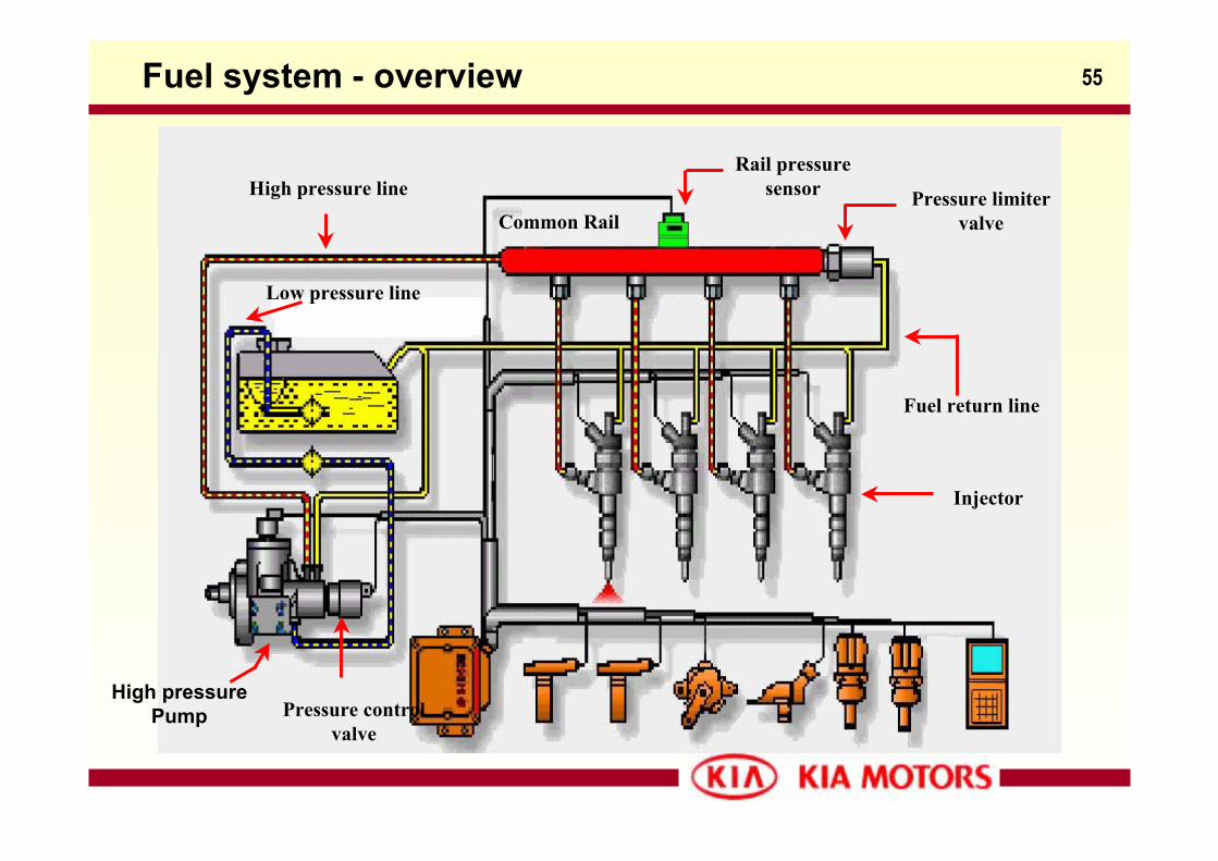
Common RailPressure limiter
valve
Injector
Pressure controlvalve
High pressure lineRail pressure
sensor
High pressurePump
Fuel return line
Low pressure line
Fuel system - overview
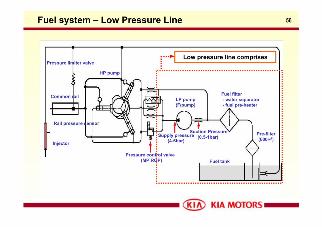
56Fuel system – Low Pressure Line
Fuel tank
Fuel filter- water separator- fuel pre-heater
Pre-filter(600)
LP pump(F/pump)
Injector
Suction Pressure(0.5-1bar)
Pressure limiter valve
Pressure control valve(MP ROP)
Common rail
Supply pressure(4-6bar)
HP pump
Low pressure line comprises
Rail pressure sensor
57Low Pressure Line – Fuel Tank
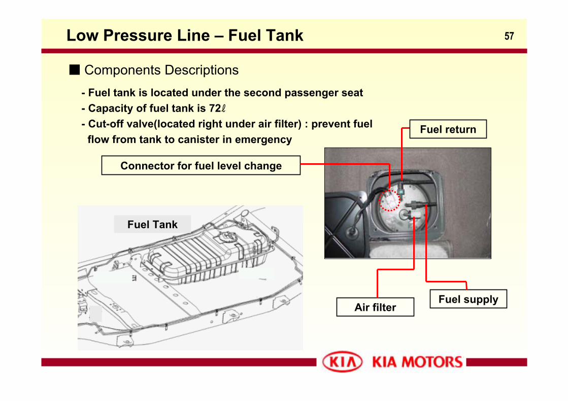
- Fuel tank is located under the second passenger seat- Capacity of fuel tank is 72ℓ- Cut-off valve(located right under air filter) : prevent fuel
flow from tank to canister in emergency
Components Descriptions
Fuel Tank
Fuel supplyAir filter
Fuel return
Connector for fuel level change
58Low Pressure Line – Fuel Module Assemble
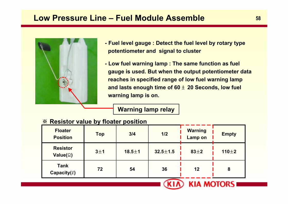
- Fuel level gauge : Detect the fuel level by rotary typepotentiometer and signal to cluster
- Low fuel warning lamp : The same function as fuelgauge is used. But when the output potentiometer datareaches in specified range of low fuel warning lampand lasts enough time of 60 ± 20 Seconds, low fuelwarning lamp is on.
812365472Tank
Capacity(ℓ)
110±283±232.5±1.518.5±13±1ResistorValue(Ω)
EmptyWarningLamp on
1/23/4TopFloater
Position
※ Resistor value by floater position
Warning lamp relay
59Low Pressure Line – Fuel Filter
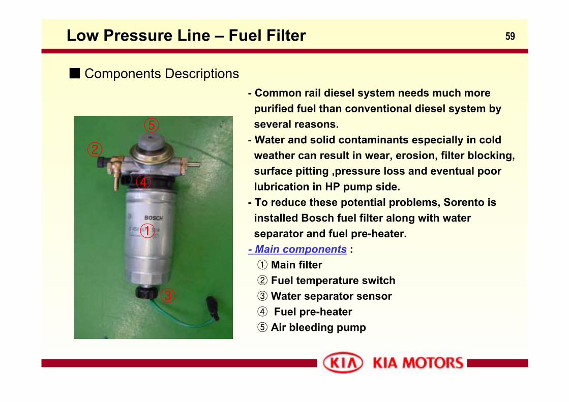
Components Descriptions- Common rail diesel system needs much more
purified fuel than conventional diesel system byseveral reasons.
- Water and solid contaminants especially in coldweather can result in wear, erosion, filter blocking, surface pitting ,pressure loss and eventual poorlubrication in HP pump side.
- To reduce these potential problems, Sorento isinstalled Bosch fuel filter along with water separator and fuel pre-heater.
- Main components :① Main filter② Fuel temperature switch③ Water separator sensor④ Fuel pre-heater⑤ Air bleeding pump
①
②
③
④
⑤
60Low Pressure Line – Fuel Heating System
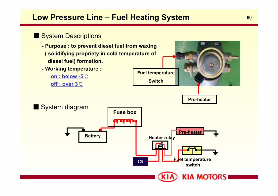
System Descriptions- Purpose : to prevent diesel fuel from waxing
( solidifying propriety in cold temperature of diesel fuel) formation.
- Working temperature : on : below -5off : over 3
가열히터커넥터
IG
Heater relayBatteryPre-heater
Fuel temperature switch
Fuse box System diagram
Fuel temperature
Switch
Pre-heater
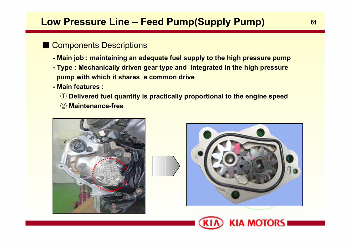
61Low Pressure Line – Feed Pump(Supply Pump)
Components Descriptions- Main job : maintaining an adequate fuel supply to the high pressure pump - Type : Mechanically driven gear type and integrated in the high pressure
pump with which it shares a common drive- Main features :
① Delivered fuel quantity is practically proportional to the engine speed② Maintenance-free
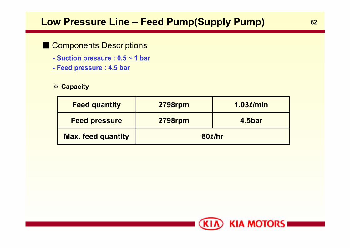
62Low Pressure Line – Feed Pump(Supply Pump)
Components Descriptions- Suction pressure : 0.5 ~ 1 bar- Feed pressure : 4.5 bar
※ Capacity
80ℓ/hrMax. feed quantity
4.5bar2798rpmFeed pressure
1.03ℓ/min2798rpmFeed quantity
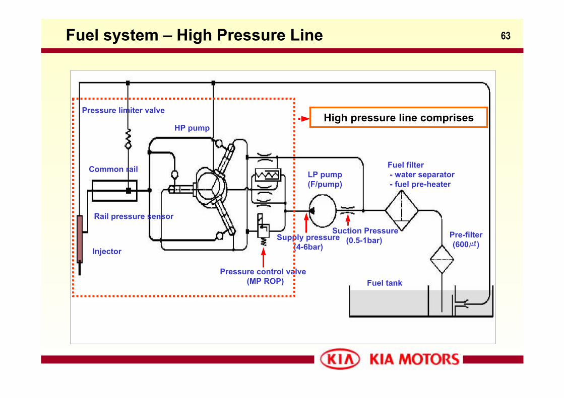
63Fuel system – High Pressure Line
Fuel tank
Fuel filter- water separator- fuel pre-heater
Pre-filter(600)
LP pump(F/pump)
Injector
Suction Pressure(0.5-1bar)
Pressure limiter valve
Pressure control valve(MP ROP)
Common rail
Supply pressure(4-6bar)
HP pumpHigh pressure line comprises
Rail pressure sensor
64High Pressure Line – Pressure Control Valve
Components Descriptions- Main function : To control the injection pressure to the engine’s requirements
which are calculated according to engine speed and load.
① Engine speed and load are high : The degree of turbulence in combustionchamber is very great so the highly pressurized fuel has to optimizecombustion.
② Engine speed and load are low : If injection pressure is too high in low load stage, the nozzle’s penetration will be excessive and part of the fuel will besprayed directly onto the sides of the cylinder, causing the formation of smoke and unburned hydrocarbons.
- Pressure control process :
① Measure the current rail pressure by rail pressure sensor② Signal to EDC(Electronic Diesel Control) ③ Calculate the adequate fuel demand by engine speed and load④ Control the “pressure control valve to reach the required value by PWM
(Pulse-width modulation)
65High Pressure Line – Pressure Control Valve
Components Descriptions
- Types :① Outlet control : located at the end of accumulator line and control the output
pressure from H/P pump by increasing or decreasing the total return fuelquantity
② Inlet control : integrated with H/P pump and control the fuel quantity from feed pump to high pressure pump
※ Merit of outlet control type minimize the increasing fuel temperature only supplying optimized
fuel volume driving torque is decreased by 3~4kg-m
Demerit difficult to release unneeded rail pressure in sudden deceleration
condition
66
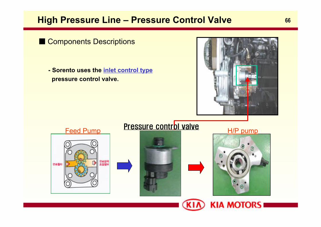
- Sorento uses the inlet control typepressure control valve.
Pressure control valve H/P pumpFeed Pump
High Pressure Line – Pressure Control Valve
Components Descriptions
67
Components Descriptions
High Pressure Line – Pressure Control Valve
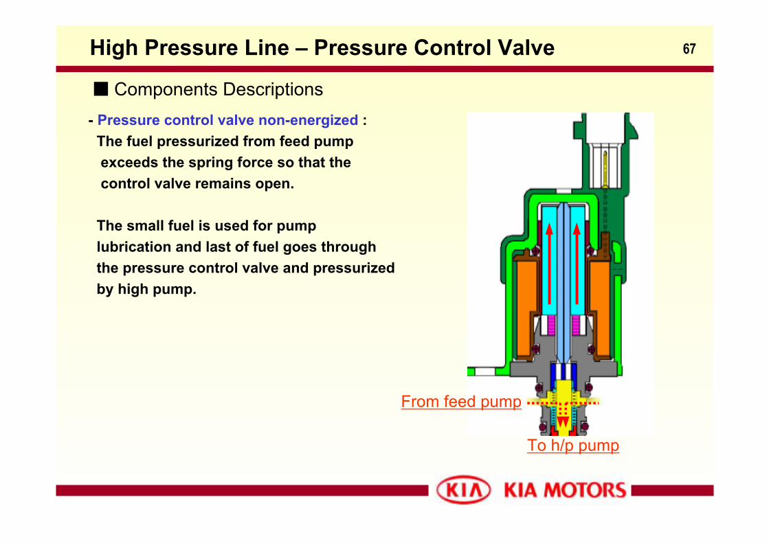
- Pressure control valve non-energized : The fuel pressurized from feed pump exceeds the spring force so that the control valve remains open.
The small fuel is used for pump lubrication and last of fuel goes through the pressure control valve and pressurizedby high pump.
From feed pump
To h/p pump
68
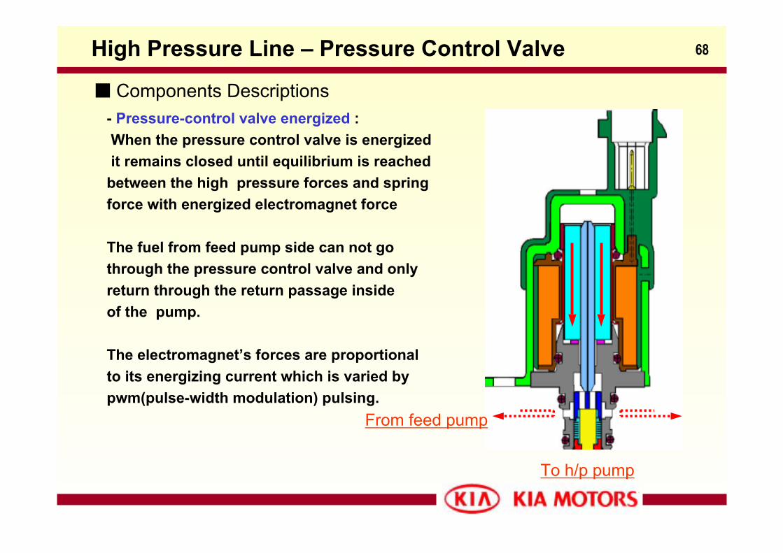
- Pressure-control valve energized : When the pressure control valve is energized it remains closed until equilibrium is reached
between the high pressure forces and spring force with energized electromagnet force
The fuel from feed pump side can not go through the pressure control valve and only return through the return passage inside of the pump.
The electromagnet’s forces are proportionalto its energizing current which is varied bypwm(pulse-width modulation) pulsing.
Components Descriptions
From feed pump
To h/p pump
High Pressure Line – Pressure Control Valve
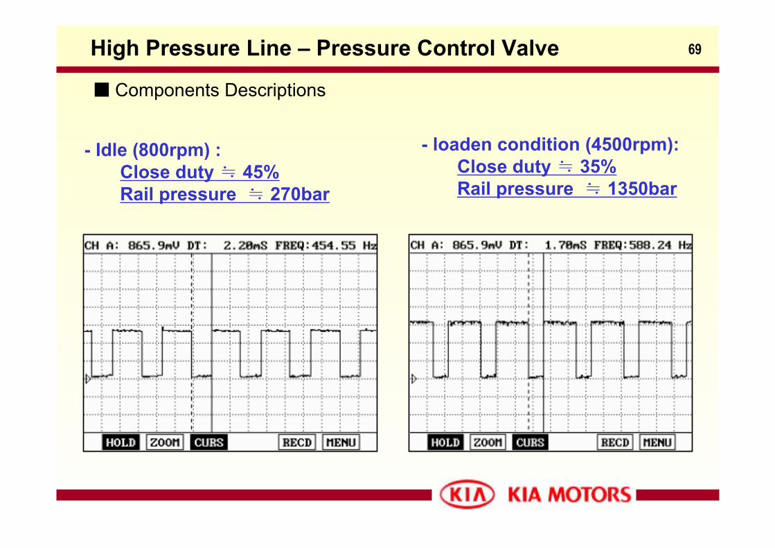
69
- Idle (800rpm) :Close duty ≒ 45% Rail pressure ≒ 270bar
Components Descriptions
High Pressure Line – Pressure Control Valve
- loaden condition (4500rpm):Close duty ≒ 35% Rail pressure ≒ 1350bar
70
H/P pump
Pressurecontrolvalve
Feed pump
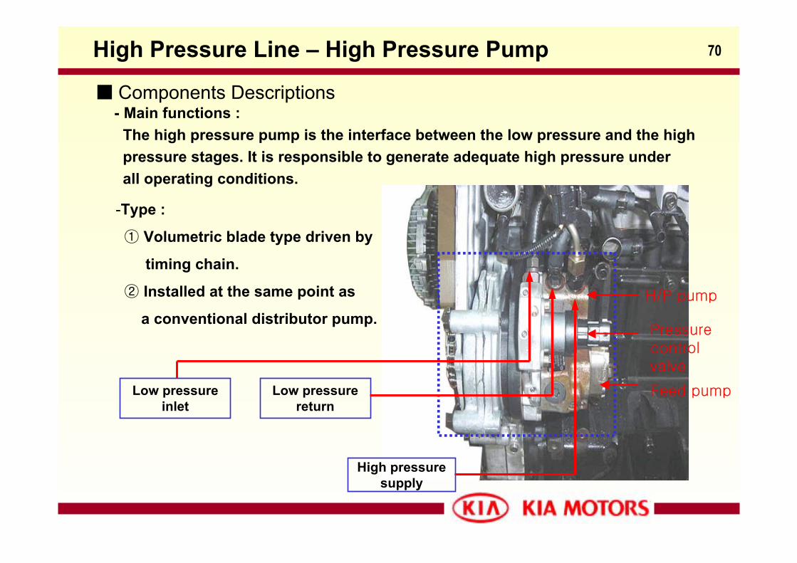
High Pressure Line – High Pressure Pump
Components Descriptions- Main functions :
The high pressure pump is the interface between the low pressure and the highpressure stages. It is responsible to generate adequate high pressure underall operating conditions.
-Type :
① Volumetric blade type driven by
timing chain.
② Installed at the same point as
a conventional distributor pump.
High pressuresupply
Low pressure return
Low pressure inlet
71
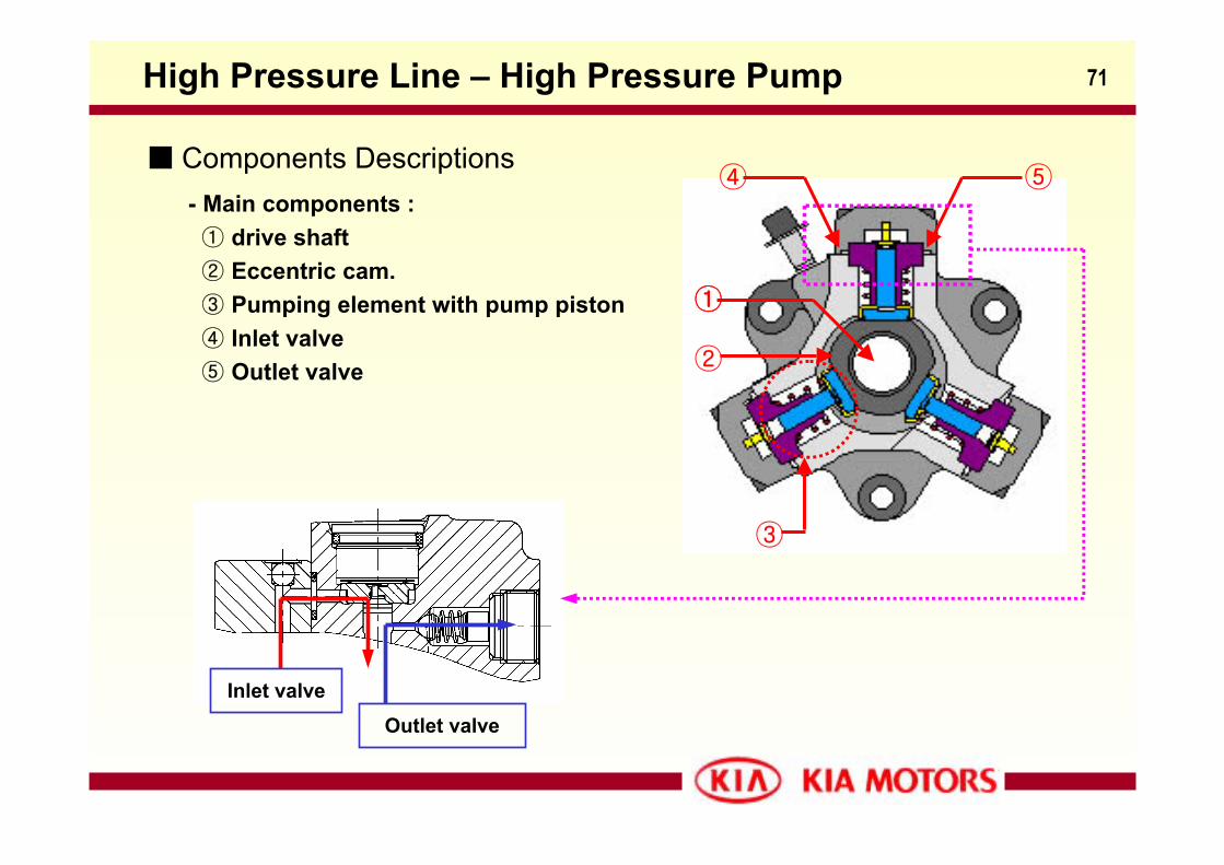
Components Descriptions
High Pressure Line – High Pressure Pump
- Main components :① drive shaft② Eccentric cam.③ Pumping element with pump piston④ Inlet valve⑤ Outlet valve
①
②
①
③
④ ⑤
Inlet valveOutlet valve
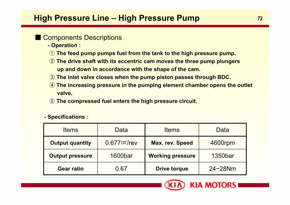
72
Components Descriptions- Operation : ① The feed pump pumps fuel from the tank to the high pressure pump.② The drive shaft with its eccentric cam moves the three pump plungers
up and down in accordance with the shape of the cam.③ The inlet valve closes when the pump piston passes through BDC.④ The increasing pressure in the pumping element chamber opens the outlet
valve.⑤ The compressed fuel enters the high pressure circuit.
High Pressure Line – High Pressure Pump
- Specifications :
4600rpmMax. rev. Speed0.677/revOutput quantity
0.67
1600bar
Data
Drive torque
Working pressure
Items
24~28NmGear ratio
1350barOutput pressure
DataItems
73High Pressure Line – Common Rail
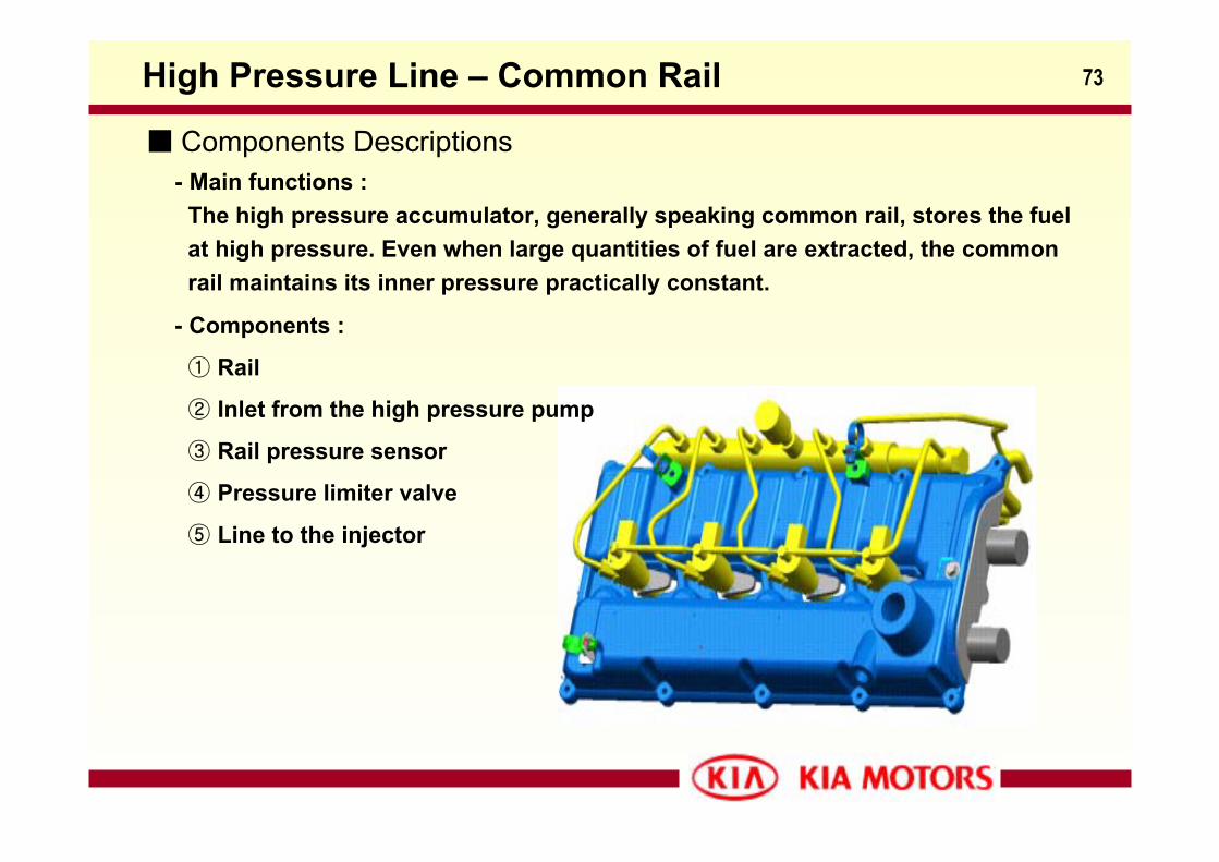
Components Descriptions- Main functions :
The high pressure accumulator, generally speaking common rail, stores the fuelat high pressure. Even when large quantities of fuel are extracted, the commonrail maintains its inner pressure practically constant.
- Components :
① Rail
② Inlet from the high pressure pump
③ Rail pressure sensor
④ Pressure limiter valve
⑤ Line to the injector
74High Pressure Line – Pressure Limiter Valve
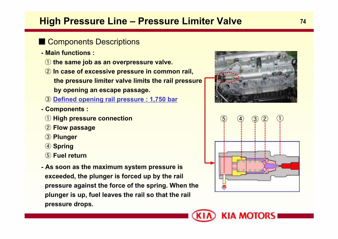
Components Descriptions- Main functions :① the same job as an overpressure valve.② In case of excessive pressure in common rail,
the pressure limiter valve limits the rail pressureby opening an escape passage.
③ Defined opening rail pressure : 1,750 bar- Components :① High pressure connection② Flow passage③ Plunger④ Spring⑤ Fuel return
①⑤ ②③④
- As soon as the maximum system pressure is exceeded, the plunger is forced up by the railpressure against the force of the spring. When theplunger is up, fuel leaves the rail so that the rail pressure drops.
75
Components Descriptions
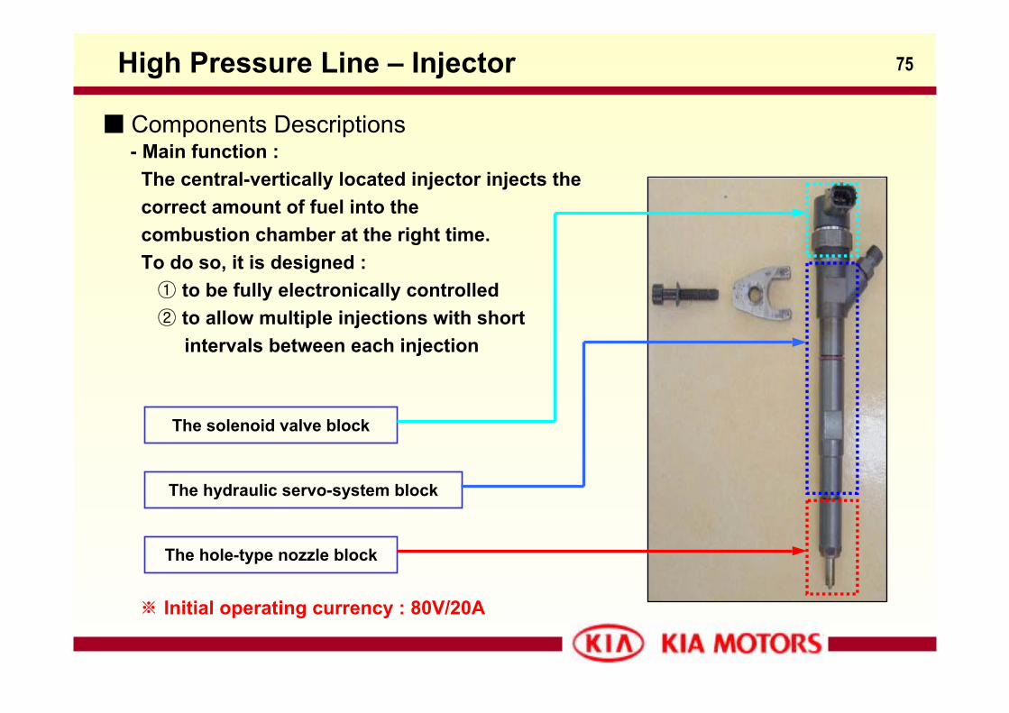
High Pressure Line – Injector
- Main function :The central-vertically located injector injects the correct amount of fuel into thecombustion chamber at the right time.To do so, it is designed :
① to be fully electronically controlled② to allow multiple injections with short
intervals between each injection
The solenoid valve block
The hydraulic servo-system block
The hole-type nozzle block
※ Initial operating currency : 80V/20A
76High Pressure Line – Injector
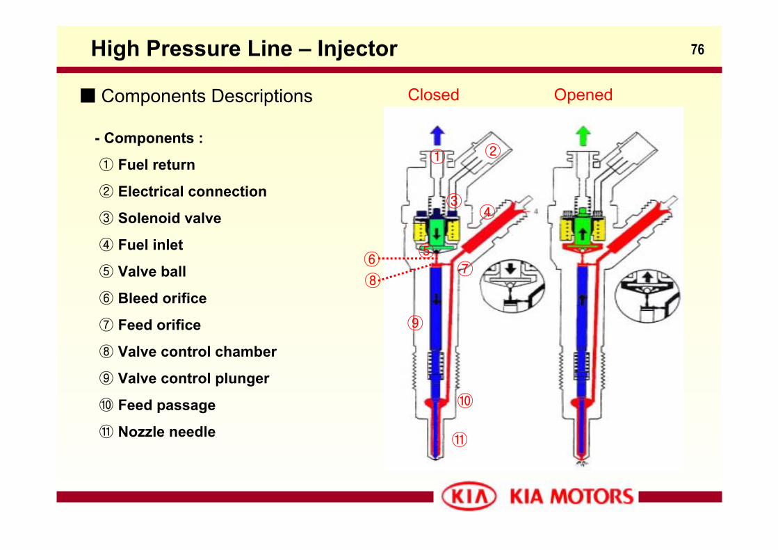
Components Descriptions
- Components :
① Fuel return
② Electrical connection
③ Solenoid valve
④ Fuel inlet
⑤ Valve ball
⑥ Bleed orifice
⑦ Feed orifice
⑧ Valve control chamber
⑨ Valve control plunger
⑩ Feed passage
⑪ Nozzle needle
OpenedClosed
③
① ②
④
⑤⑥⑦
⑧
⑨
⑩
⑪
77
Components Descriptions :- Operation :
① Injector closed (at-rest status) :The solenoid valve is not energized and the bleed orifice closed. The valve spring forces
the valve ball to the bleed orifice seat. The same pressure is present between in the valve
control chamber and in the nozzle chamber.
High Pressure Line – Injector
② Injector opens(start of injection) :The solenoid valve is energized with the pick-up current and the applied force exceeds that
of the valve spring which opens the bleed orifice. When the bleed orifice opens, fuel can
flow from the valve control chamber to the fuel tank via the fuel return. This makes pressure
unbalance between the valve control chamber and the nozzle chamber. The reduced pressure
in the valve control chamber lets the nozzle needle opens as a result and injection starts.③ Injector closed (end of injection) :
As soon as the solenoid valve is no longer energized, the valve spring forces the armature
downwards and the valve ball closes the bleed orifice. Closing the bleed orifice leads to
pressure buildup in the control chamber. Consequently this pressure buildup makes pressure
balance between in the valve control chamber and in the nozzle chamber and the nozzle needle
closes.
78High Pressure Line – Injector
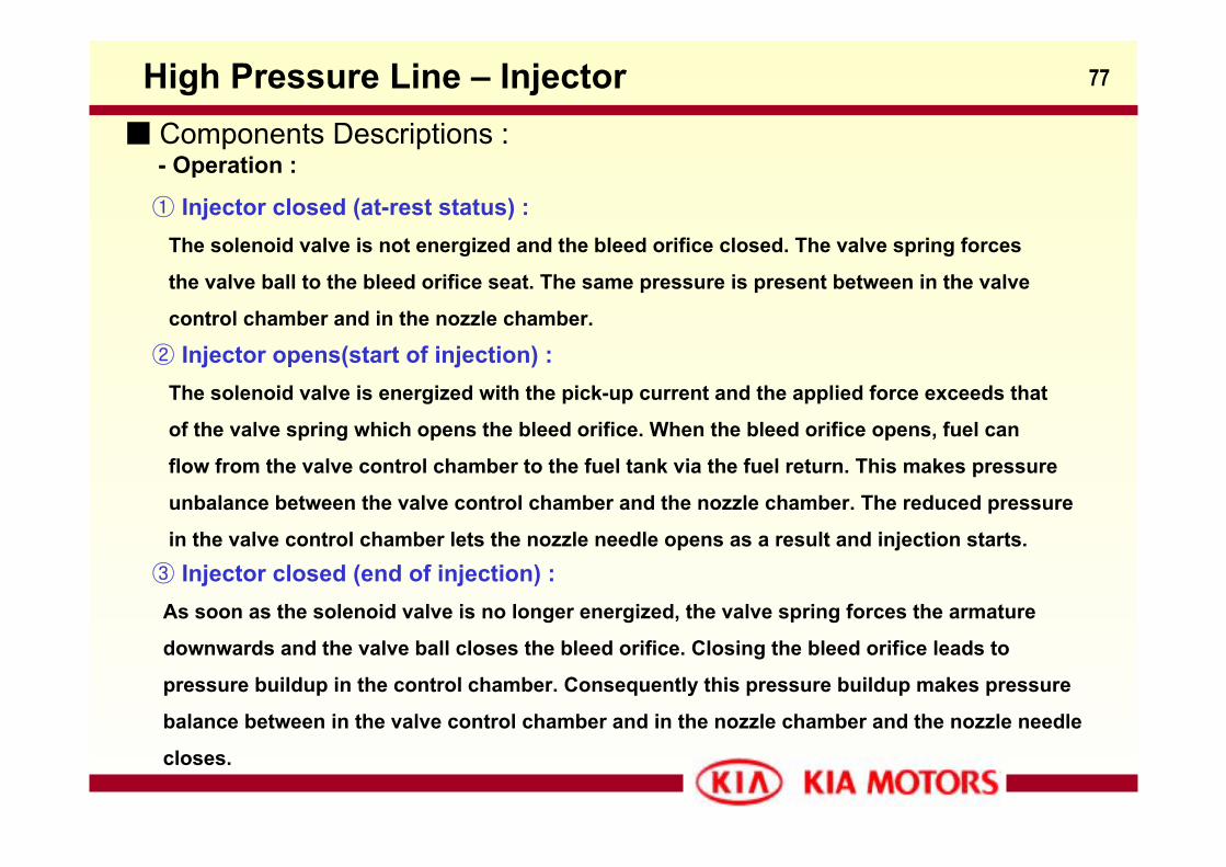
Components Descriptions :- Injection time sequence :
A = Control current
B = Stroke in mm
C = High pressure
D = Injection rate
a = Control current for solenoid coil
b = Valve lift stroke
c1 = Pressure in the control chamber
c2 = P. in the needle lift chamber
d = Injection
79
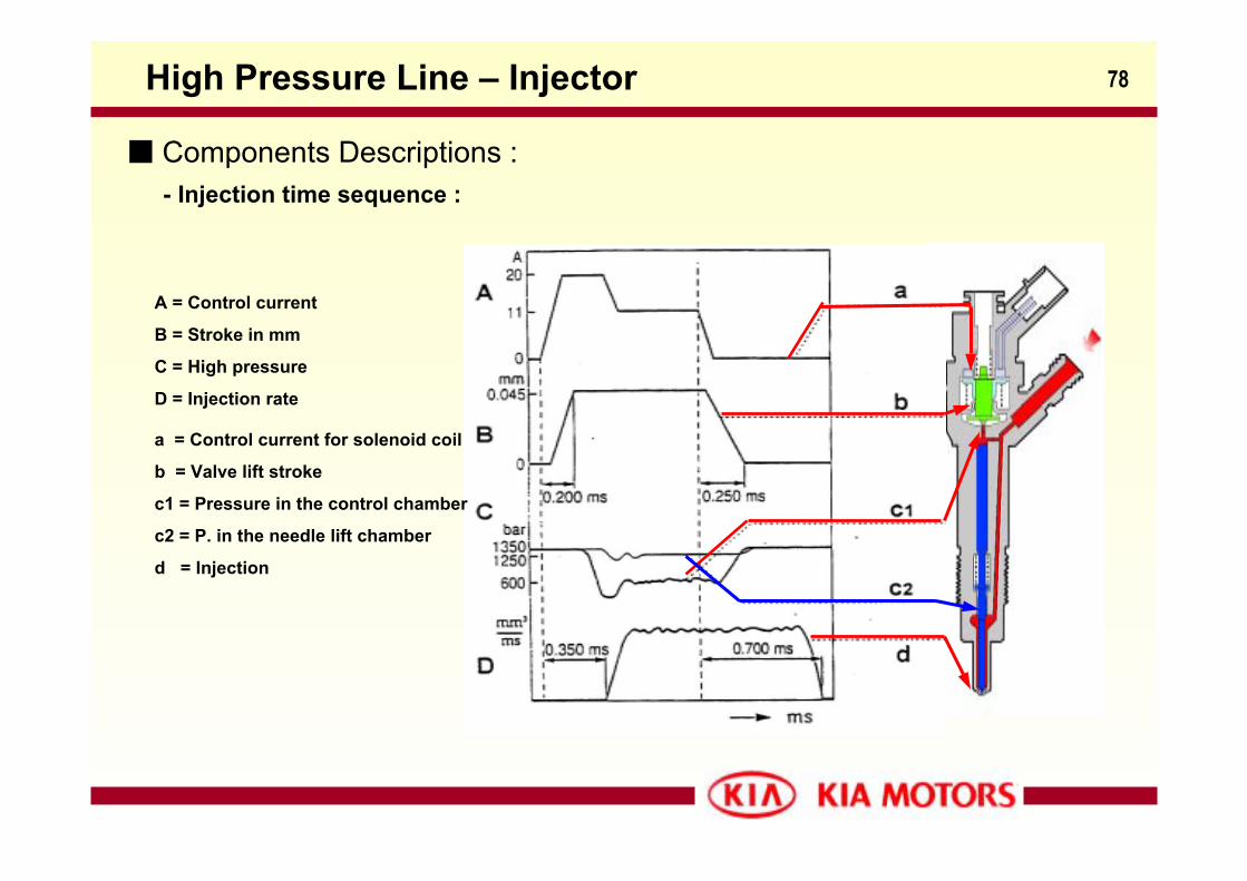
18~20A 10~12A
Injector
50% 45%
1 Capacitor disharge
2 Injector pull in current
3 Capacitor charge
4 Injector holding current
5 Capacitor charge
(PST off)
6 Regulated holding current
(free-wheeling)
7 Regulated holding current
(power stage on)
Components Descriptions :- Injector control :
High Pressure Line – Injector
80
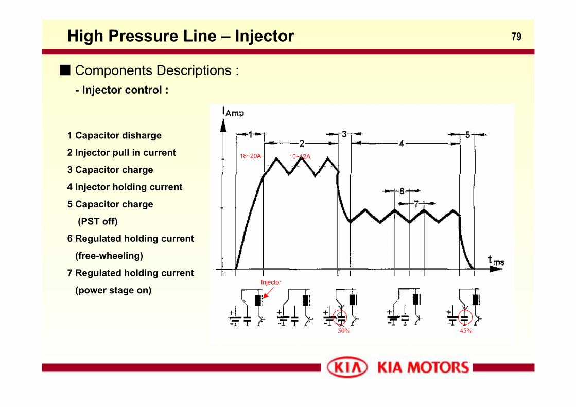
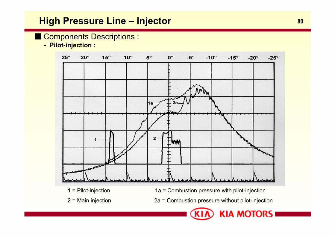
Components Descriptions :- Pilot-injection :
High Pressure Line – Injector
1 = Pilot-injection 1a = Combustion pressure with pilot-injection
2 = Main injection 2a = Combustion pressure without pilot-injection
81
Components Descriptions :- Aim of pre-injection :
High Pressure Line – Injector
Reduction in Combustion noise
① Combustion noise
② HC Emissions
③ Fuel consumption (late injection start)
- Working condition :
Idling and operation under partial load
- Principle :
In a diesel engine, combustion does not start immediately after the fuel has been
Injected into the cylinder. It makes severe combustion noise when ignition happens.
To reduce combustion noise and to make idle combustion, it is necessary to reduce
the ignition time by increasing both the vaporisation and the chemical formation.
This increase can be brought about by injecting a small quantity before the start of
the main injection. This is termed pre-injection.
82High Pressure Line – Injector
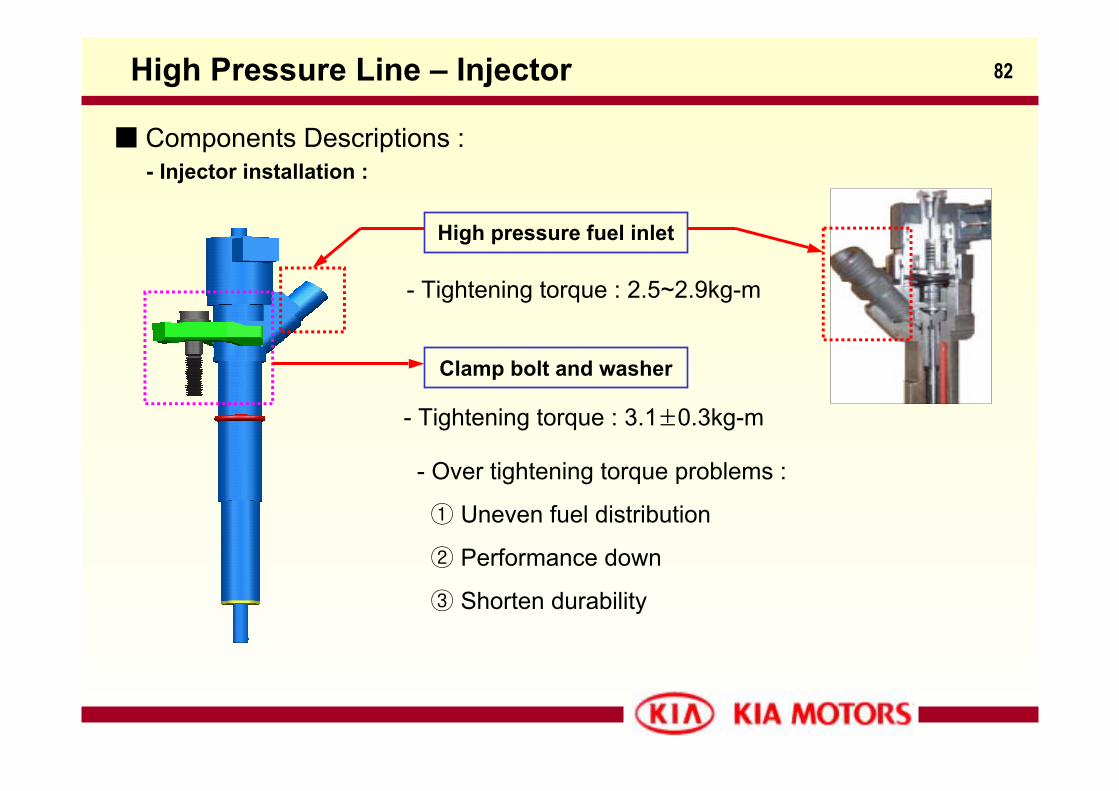
Components Descriptions :- Injector installation :
High pressure fuel inlet
- Tightening torque : 2.5~2.9kg-m
Clamp bolt and washer
- Tightening torque : 3.1±0.3kg-m
- Over tightening torque problems :
① Uneven fuel distribution
② Performance down
③ Shorten durability
83EDC
Electronic Diesel Control
(EDC)
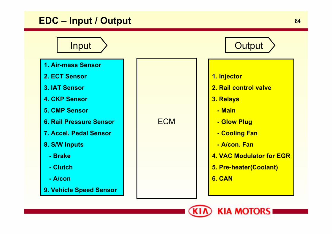
84EDC – Input / Output
Input Output
ECM
1. Air-mass Sensor
2. ECT Sensor
3. IAT Sensor
4. CKP Sensor
5. CMP Sensor
6. Rail Pressure Sensor
7. Accel. Pedal Sensor
8. S/W Inputs
- Brake
- Clutch
- A/con
9. Vehicle Speed Sensor
1. Injector
2. Rail control valve
3. Relays
- Main
- Glow Plug
- Cooling Fan
- A/con. Fan
4. VAC Modulator for EGR
5. Pre-heater(Coolant)
6. CAN
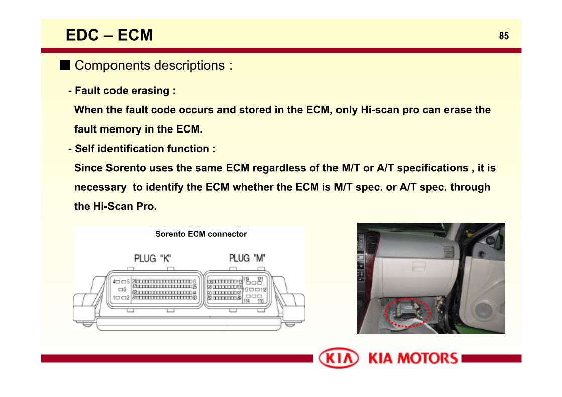
85EDC – ECM
Sorento ECM connector
Components descriptions :
- Fault code erasing :
When the fault code occurs and stored in the ECM, only Hi-scan pro can erase the
fault memory in the ECM.
- Self identification function :
Since Sorento uses the same ECM regardless of the M/T or A/T specifications , it is
necessary to identify the ECM whether the ECM is M/T spec. or A/T spec. through
the Hi-Scan Pro.
86EDC – General Items
- Limp home mode :
The ECM switches to limp home mode in the event of failure of important input/
output signals. This can result in
① Reduced power
② Lower maximum speed
③ No EGR (It depends on items)
- Emergency shut off
For safety reasons, the ECM effects emergency shut off of the engine if the
following system components fail :
① Injectors
② CKP sensor
③ Pressure control valve
④ Fuel leakage
- Attention : Never work on injection system with engine running or with in 30 Sec.
after shutting off the engine.
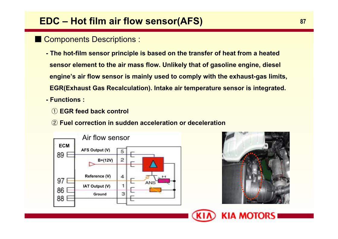
87EDC – Hot film air flow sensor(AFS)
Components Descriptions :- The hot-film sensor principle is based on the transfer of heat from a heated
sensor element to the air mass flow. Unlikely that of gasoline engine, diesel
engine’s air flow sensor is mainly used to comply with the exhaust-gas limits,
EGR(Exhaust Gas Recalculation). Intake air temperature sensor is integrated.
- Functions :
① EGR feed back control
② Fuel correction in sudden acceleration or deceleration
Air flow sensorECM
AFS Output (V)
Reference (V)
B+(12V)
IAT Output (V)
Ground
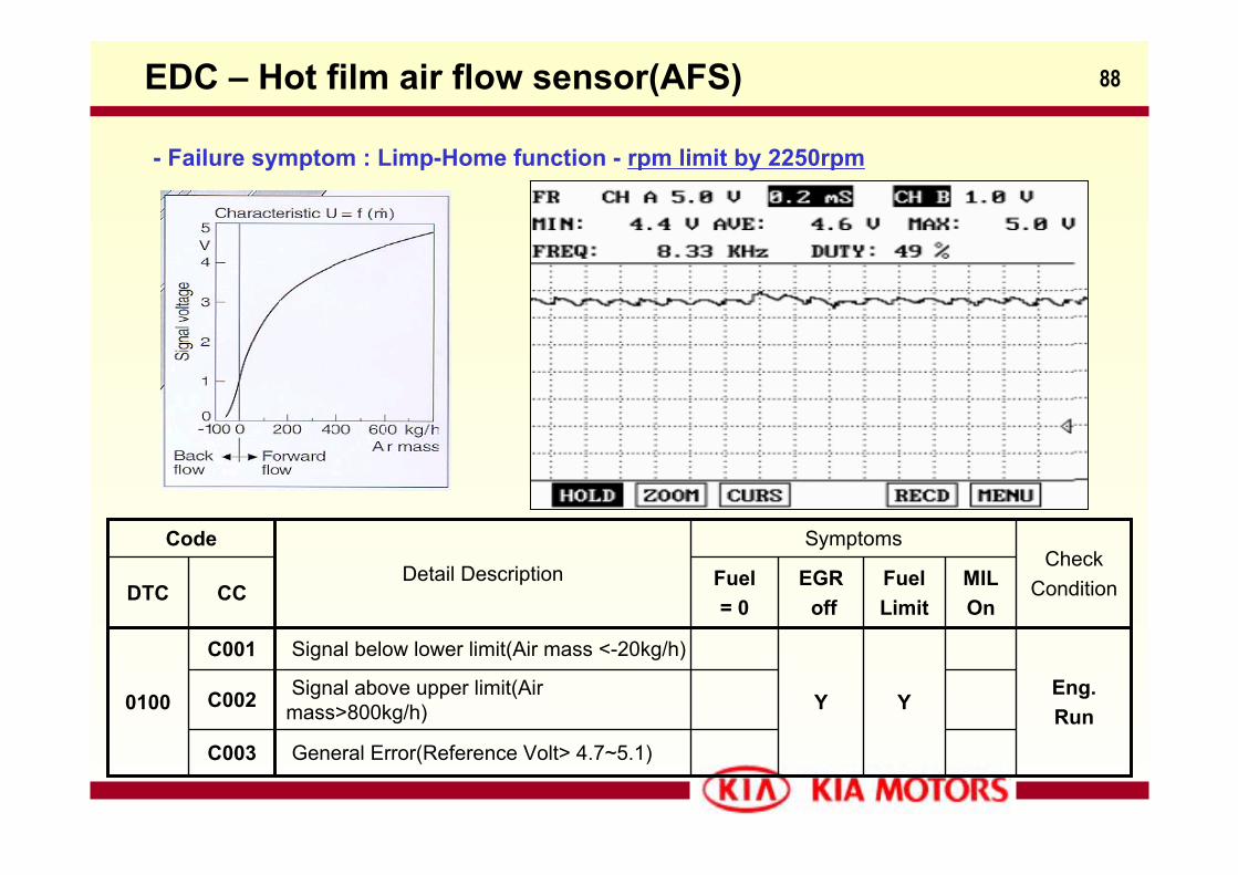
88
- Failure symptom : Limp-Home function - rpm limit by 2250rpm
EDC – Hot film air flow sensor(AFS)
Y
Fuel Limit
General Error(Reference Volt> 4.7~5.1)C003
Signal above upper limit(Air mass>800kg/h)C002 Eng.
RunY
Signal below lower limit(Air mass <-20kg/h)C001
0100
MILOn
EGRoff
Fuel= 0
CCDTCCheck
Condition
Symptoms
Detail Description
Code
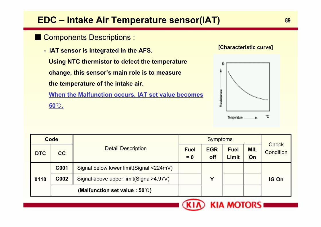
89EDC – Intake Air Temperature sensor(IAT)
Components Descriptions :
Fuel Limit
(Malfunction set value : 50)
Signal above upper limit(Signal>4.97V)C002 IG OnY
Signal below lower limit(Signal <224mV)C001
0110
MILOn
EGRoff
Fuel= 0
CCDTCCheck
Condition
Symptoms
Detail Description
Code
- IAT sensor is integrated in the AFS.
Using NTC thermistor to detect the temperature
change, this sensor’s main role is to measure
the temperature of the intake air.
When the Malfunction occurs, IAT set value becomes
50.
[Characteristic curve]
90EDC – Accelerator-pedal sensor(APS)
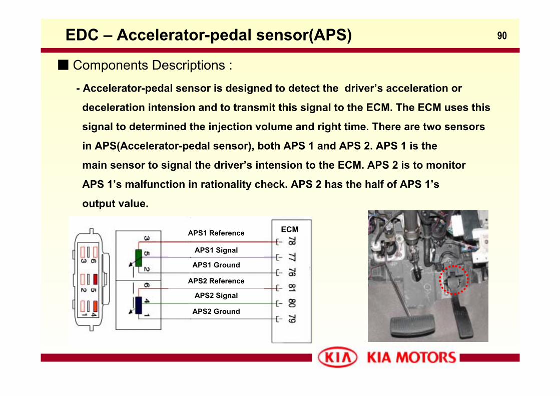
Components Descriptions :- Accelerator-pedal sensor is designed to detect the driver’s acceleration or
deceleration intension and to transmit this signal to the ECM. The ECM uses this
signal to determined the injection volume and right time. There are two sensors
in APS(Accelerator-pedal sensor), both APS 1 and APS 2. APS 1 is the
main sensor to signal the driver’s intension to the ECM. APS 2 is to monitor
APS 1’s malfunction in rationality check. APS 2 has the half of APS 1’s
output value.
APS1 Reference
APS1 Signal
APS1 Ground
APS2 Reference
APS2 Signal
APS2 Ground
ECM
91
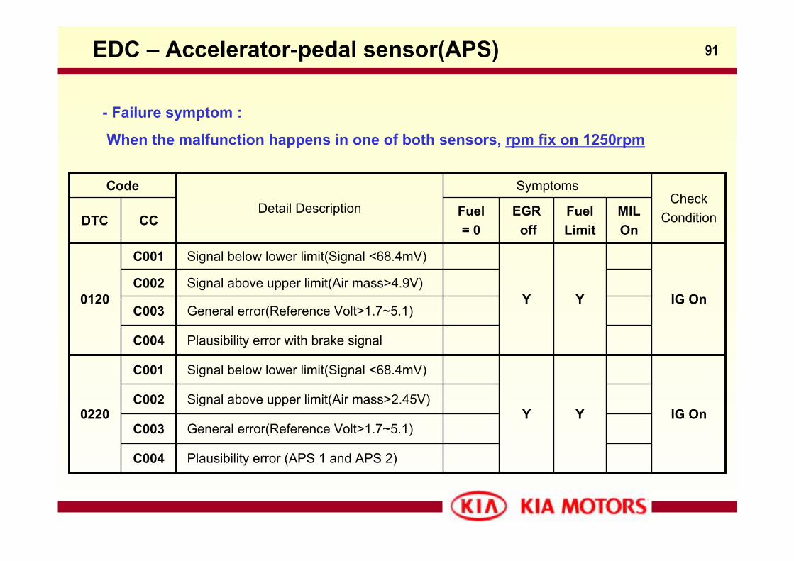
General error(Reference Volt>1.7~5.1)C003IG On
Plausibility error with brake signalC004
IG OnYY
Signal below lower limit(Signal <68.4mV)C001
0220Signal above upper limit(Air mass>2.45V)C002
General error(Reference Volt>1.7~5.1)C003
Y
Fuel Limit
Plausibility error (APS 1 and APS 2)C004
Signal above upper limit(Air mass>4.9V)C002Y
Signal below lower limit(Signal <68.4mV)C001
0120
MILOn
EGRoff
Fuel= 0
CCDTCCheck
Condition
Symptoms
Detail Description
Code
EDC – Accelerator-pedal sensor(APS)
- Failure symptom :
When the malfunction happens in one of both sensors, rpm fix on 1250rpm
92
- Plausibility error with brake signal (0120-C004) :
When the driver presses the accelerator pedal more than 1% and simultaneously
presses the brake pedal (brake switch on), the ECM consider this condition as an
abnormal accelerator pedal working ,kind of accelerator pedal’s stuck in not-idle
position. Other purpose to utilize this plausibility check is to prevent from sudden
unintended acceleration of pedal misapplication by driver.
- Plausibility error between APS 1 and APS 2 (0220-C004) :
When the result of compared difference from APS 1 and APS 2 is over than set value,
for example the press rate of accelerator pedal is 1.8 ~ 6% : 308mV
the press rate of accelerator pedal is 7% : 406mV
the ECM considers this as a fault of APS 1 or APS 2 in the name of rationality check.
EDC – Accelerator-pedal sensor(APS)
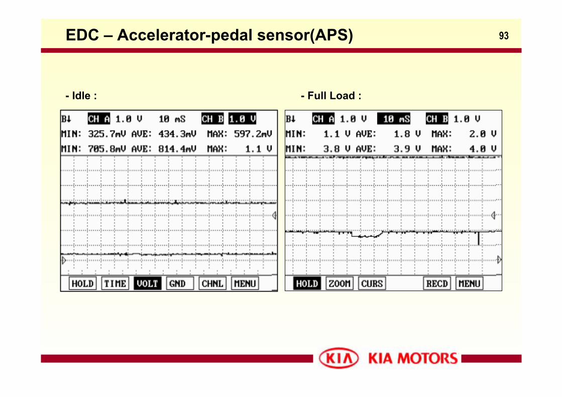
93EDC – Accelerator-pedal sensor(APS)
- Idle : - Full Load :
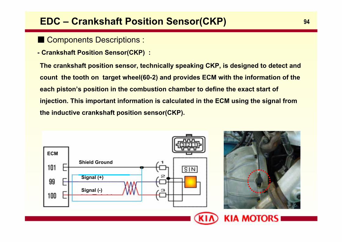
94EDC – Crankshaft Position Sensor(CKP)
The crankshaft position sensor, technically speaking CKP, is designed to detect and
count the tooth on target wheel(60-2) and provides ECM with the information of the
each piston’s position in the combustion chamber to define the exact start of
injection. This important information is calculated in the ECM using the signal from
the inductive crankshaft position sensor(CKP).
Components Descriptions :- Crankshaft Position Sensor(CKP) :
Shield Ground
ECM
Signal (+)
Signal (-)
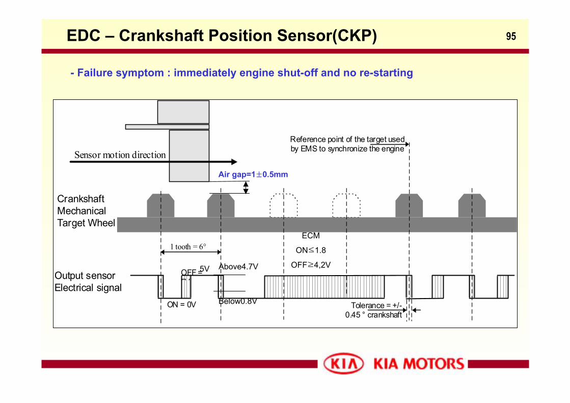
95EDC – Crankshaft Position Sensor(CKP)
- Failure symptom : immediately engine shut-off and no re-starting
CrankshaftMechanicalTarget Wheel
ON = 0V
Output sensorElectrical signal
1 tooth = 6°
Tolerance = +/-0.45 ° crankshaft
OFF =5V
Reference point of the target usedby EMS to synchronize the engineSensor motion direction
Air gap=1±0.5mm
5V Above4.7V
Below0.8V
ECM
ON≤1.8
OFF≥4,2V
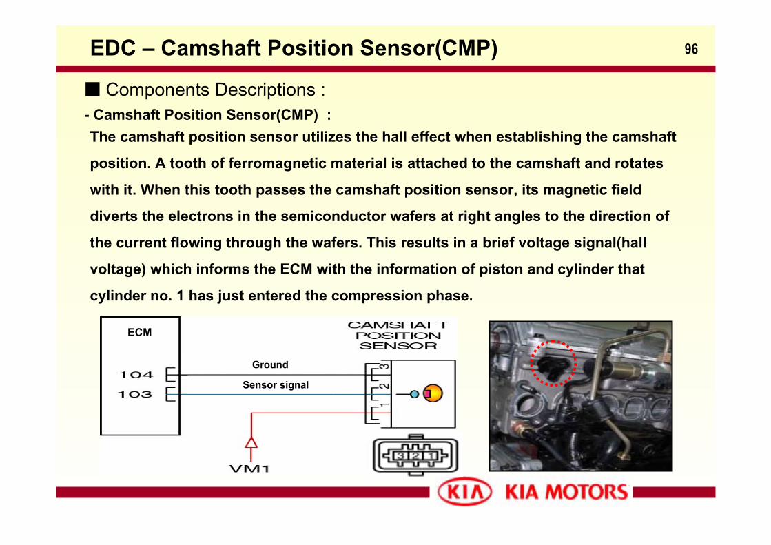
96EDC – Camshaft Position Sensor(CMP)
Components Descriptions :- Camshaft Position Sensor(CMP) :The camshaft position sensor utilizes the hall effect when establishing the camshaft
position. A tooth of ferromagnetic material is attached to the camshaft and rotates
with it. When this tooth passes the camshaft position sensor, its magnetic field
diverts the electrons in the semiconductor wafers at right angles to the direction of
the current flowing through the wafers. This results in a brief voltage signal(hall
voltage) which informs the ECM with the information of piston and cylinder that
cylinder no. 1 has just entered the compression phase.
Ground
Sensor signal
ECM
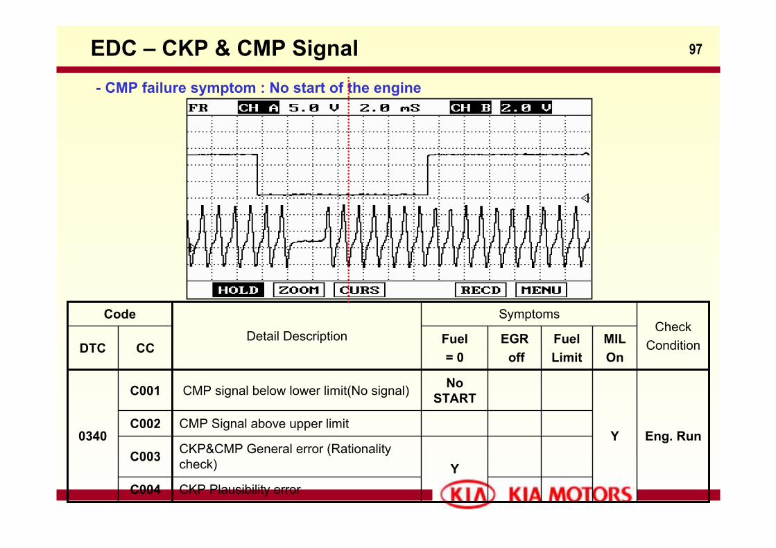
97EDC – CKP & CMP Signal
YCKP&CMP General error (Rationality check)C003
Fuel Limit
CKP Plausibility errorC004
CMP Signal above upper limitC002Eng. RunY
No STARTCMP signal below lower limit(No signal)C001
0340
MILOn
EGRoff
Fuel= 0
CCDTCCheck
Condition
Symptoms
Detail Description
Code
- CMP failure symptom : No start of the engine
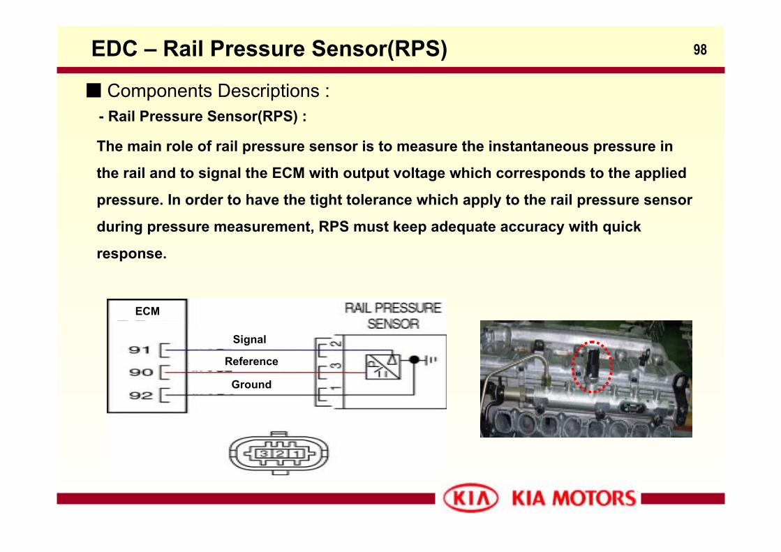
98EDC – Rail Pressure Sensor(RPS)
Components Descriptions :- Rail Pressure Sensor(RPS) :
The main role of rail pressure sensor is to measure the instantaneous pressure in
the rail and to signal the ECM with output voltage which corresponds to the applied
pressure. In order to have the tight tolerance which apply to the rail pressure sensor
during pressure measurement, RPS must keep adequate accuracy with quick
response.
Signal
Reference
Ground
ECM
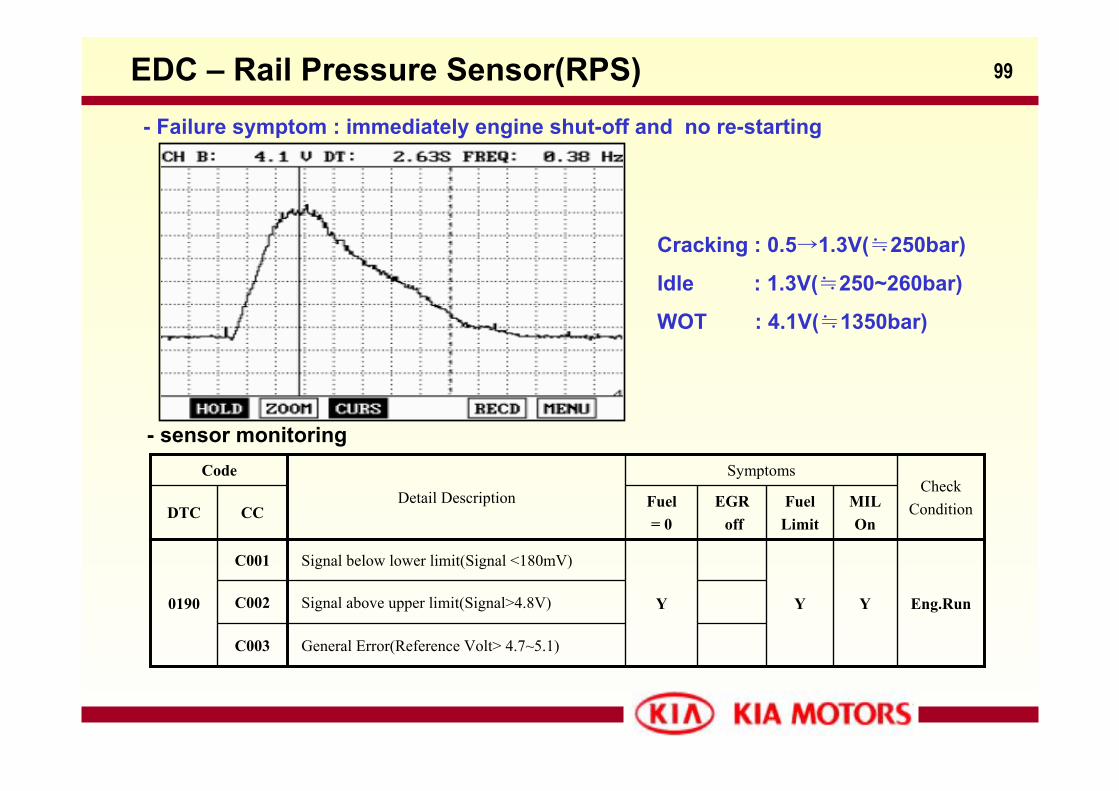
99EDC – Rail Pressure Sensor(RPS)- Failure symptom : immediately engine shut-off and no re-starting
Y
Fuel Limit
General Error(Reference Volt> 4.7~5.1)C003
Signal above upper limit(Signal>4.8V)C002 Eng.RunYYY
Signal below lower limit(Signal <180mV)C001
0190
MILOn
EGRoff
Fuel= 0
CCDTC
CheckCondition
Symptoms
Detail Description
Code
- sensor monitoring
Cracking : 0.5→1.3V(≒250bar)
Idle : 1.3V(≒250~260bar)
WOT : 4.1V(≒1350bar)
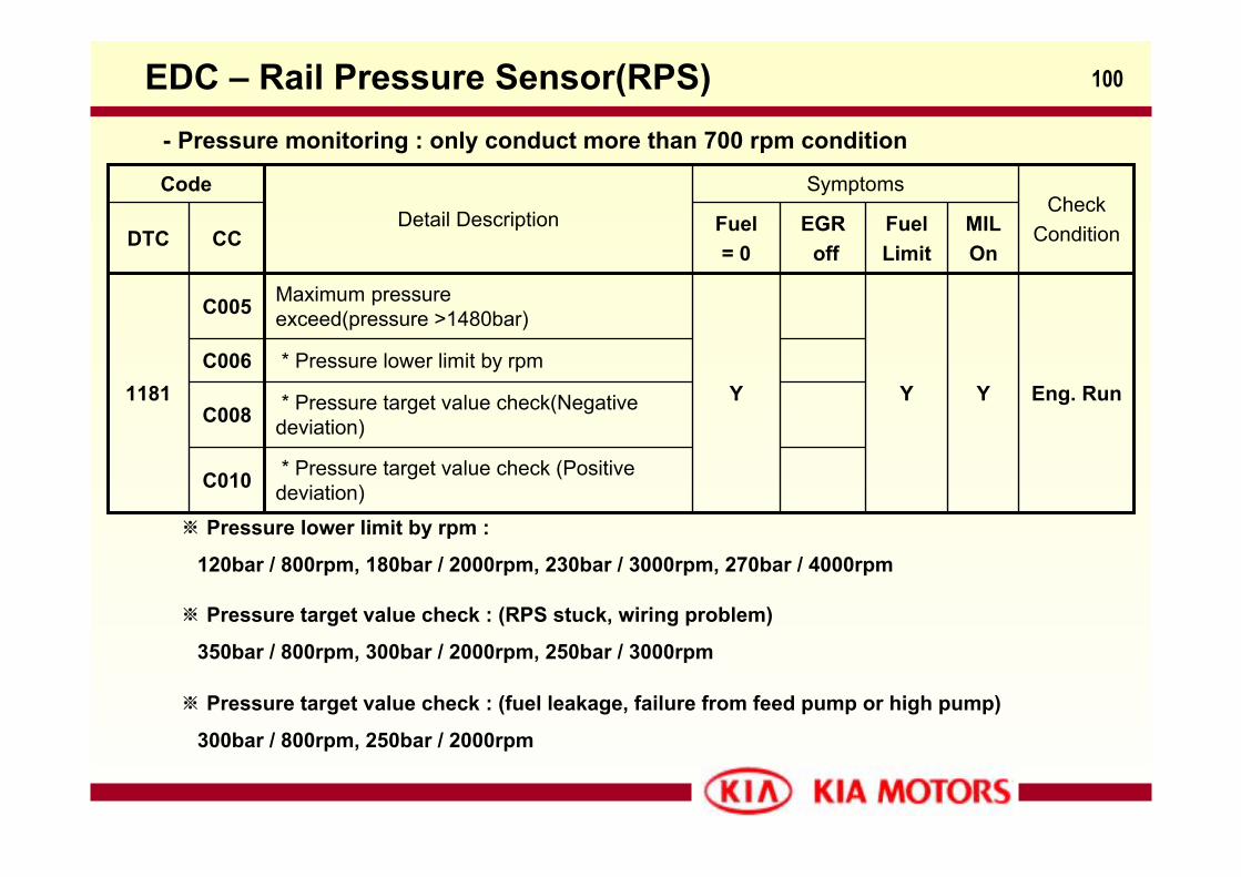
100EDC – Rail Pressure Sensor(RPS)
* Pressure target value check(Negative deviation)C008
Y
Fuel Limit
* Pressure target value check (Positive deviation)C010
* Pressure lower limit by rpmC006Eng. RunYY
Maximum pressure exceed(pressure >1480bar)C005
1181
MILOn
EGRoff
Fuel= 0
CCDTCCheck
Condition
Symptoms
Detail Description
Code
- Pressure monitoring : only conduct more than 700 rpm condition
※ Pressure lower limit by rpm :
120bar / 800rpm, 180bar / 2000rpm, 230bar / 3000rpm, 270bar / 4000rpm
※ Pressure target value check : (RPS stuck, wiring problem)
350bar / 800rpm, 300bar / 2000rpm, 250bar / 3000rpm
※ Pressure target value check : (fuel leakage, failure from feed pump or high pump)
300bar / 800rpm, 250bar / 2000rpm
101EDC – Engine Coolant Temperature Sensor(ECT)
Heat gauge unit
Ground
Signal
ECM
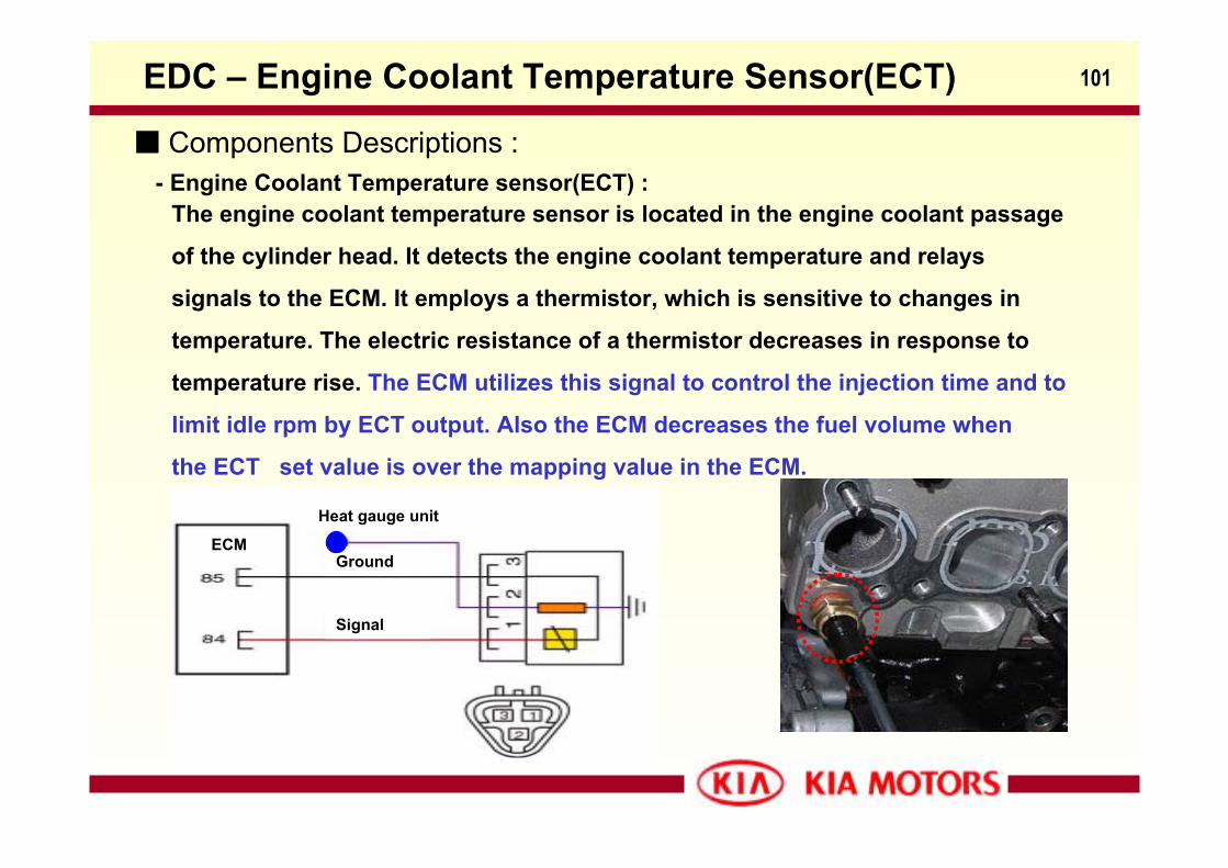
Components Descriptions :- Engine Coolant Temperature sensor(ECT) :
The engine coolant temperature sensor is located in the engine coolant passage
of the cylinder head. It detects the engine coolant temperature and relays
signals to the ECM. It employs a thermistor, which is sensitive to changes in
temperature. The electric resistance of a thermistor decreases in response to
temperature rise. The ECM utilizes this signal to control the injection time and to
limit idle rpm by ECT output. Also the ECM decreases the fuel volume when
the ECT set value is over the mapping value in the ECM.
102
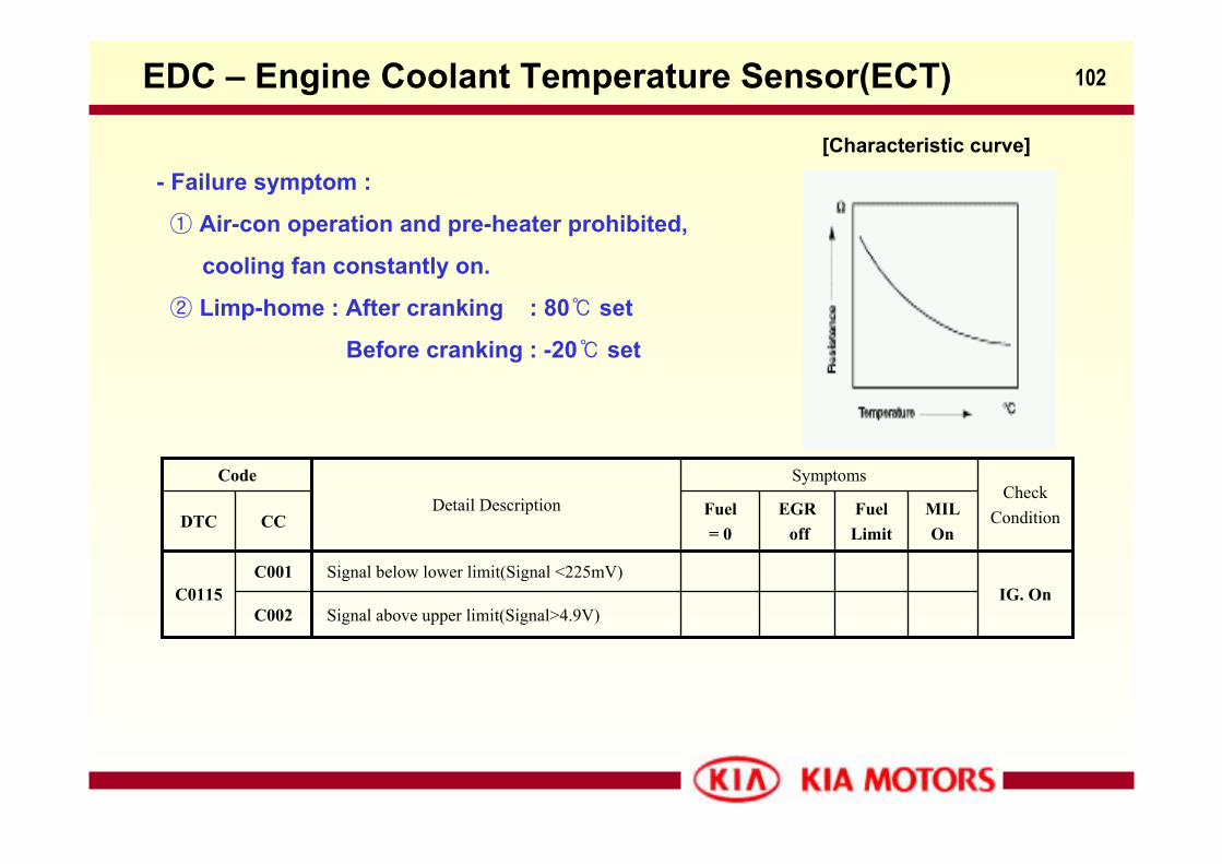
[Characteristic curve]
EDC – Engine Coolant Temperature Sensor(ECT)
- Failure symptom :
① Air-con operation and pre-heater prohibited,
cooling fan constantly on.
② Limp-home : After cranking : 80 set
Before cranking : -20 set
IG. OnSignal below lower limit(Signal <225mV)C001
C0115
Fuel Limit
Signal above upper limit(Signal>4.9V)C002
MILOn
EGRoff
Fuel= 0
CCDTC
CheckCondition
Symptoms
Detail Description
Code
103EDC – Brake switch
Brake switch 1
Brake switch 2
ECM
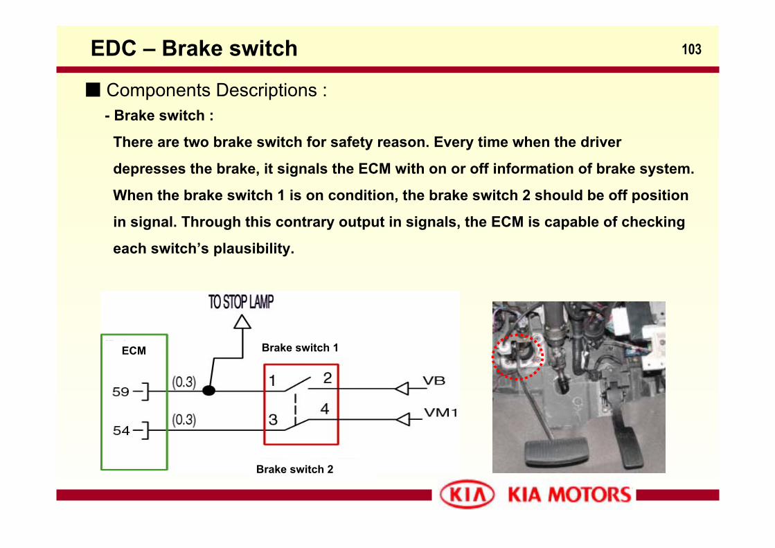
Components Descriptions :- Brake switch :
There are two brake switch for safety reason. Every time when the driver
depresses the brake, it signals the ECM with on or off information of brake system.
When the brake switch 1 is on condition, the brake switch 2 should be off position
in signal. Through this contrary output in signals, the ECM is capable of checking
each switch’s plausibility.
104
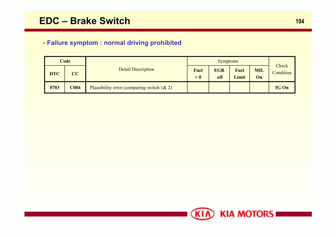
0703 IG On
Fuel Limit
Plausibility error (comparing switch 1& 2)C004
MILOn
EGRoff
Fuel= 0
CCDTC
CheckCondition
Symptoms
Detail Description
Code
EDC – Brake Switch
- Failure symptom : normal driving prohibited
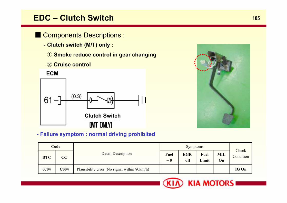
105EDC – Clutch Switch
Components Descriptions :- Clutch switch (M/T) only :
① Smoke reduce control in gear changing
② Cruise control
Clutch Switch
ECM
- Failure symptom : normal driving prohibited
0704 IG On
Fuel Limit
Plausibility error (No signal within 80km/h)C004
MILOn
EGRoff
Fuel= 0
CCDTC
CheckCondition
Symptoms
Detail Description
Code
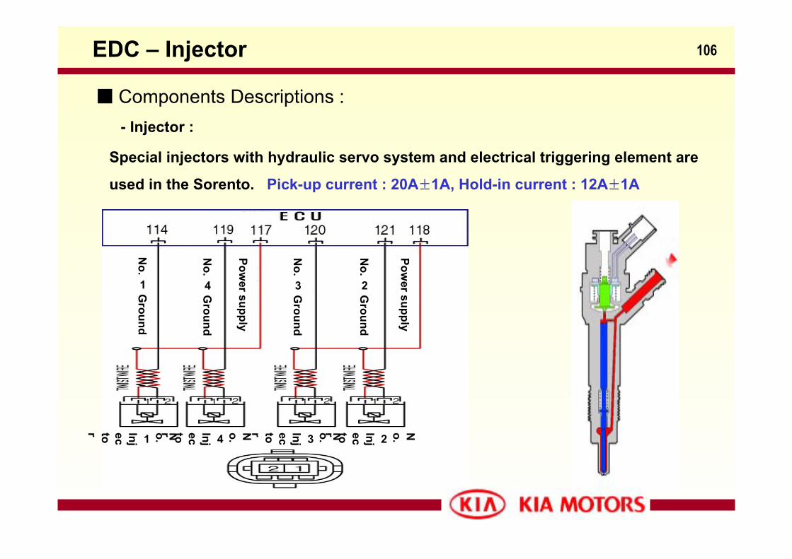
106EDC – Injector
No.
1Ground
No.
4Ground
No.
3Ground
No.
2Ground
Power supply
Power supply
No.1
Injector No.4
Injector No.3
Injector No.2Injector
Components Descriptions :- Injector :
Special injectors with hydraulic servo system and electrical triggering element are
used in the Sorento. Pick-up current : 20A±1A, Hold-in current : 12A±1A
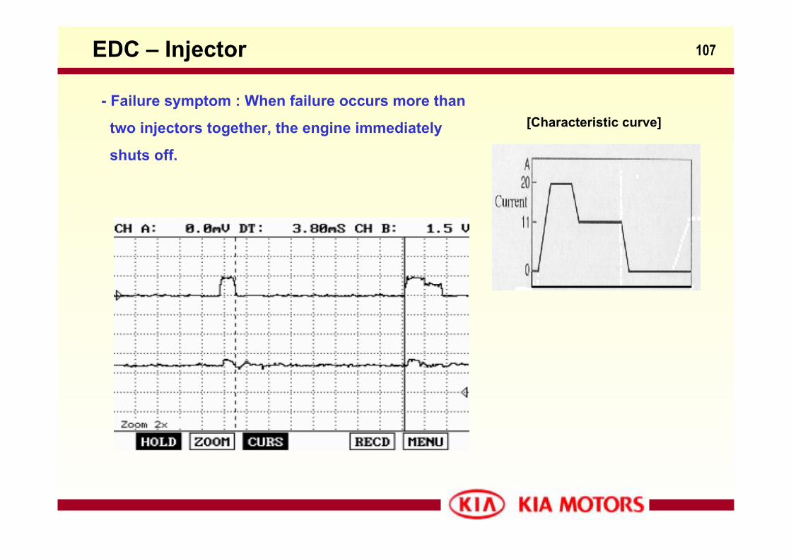
107EDC – Injector
[Characteristic curve]- Failure symptom : When failure occurs more than
two injectors together, the engine immediately
shuts off.
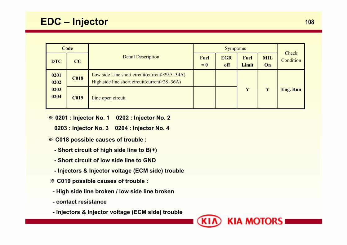
108EDC – Injector
Eng. RunYY
Low side Line short circuit(current>29.5~34A)High side line short circuit(current>28~36A)
C0180201020202030204
Fuel Limit
Line open circuitC019
MILOn
EGRoff
Fuel= 0
CCDTC
CheckCondition
Symptoms
Detail Description
Code
※ 0201 : Injector No. 1 0202 : Injector No. 2
0203 : Injector No. 3 0204 : Injector No. 4
※ C018 possible causes of trouble :
- Short circuit of high side line to B(+)
- Short circuit of low side line to GND
- Injectors & Injector voltage (ECM side) trouble
※ C019 possible causes of trouble :
- High side line broken / low side line broken
- contact resistance
- Injectors & Injector voltage (ECM side) trouble
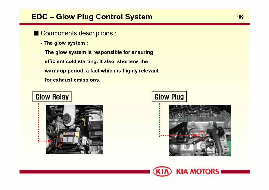
109
Components descriptions : - The glow system :
The glow system is responsible for ensuring
efficient cold starting. It also shortens the
warm-up period, a fact which is highly relevant
for exhaust emissions.
EDC – Glow Plug Control System
Glow Relay Glow Plug
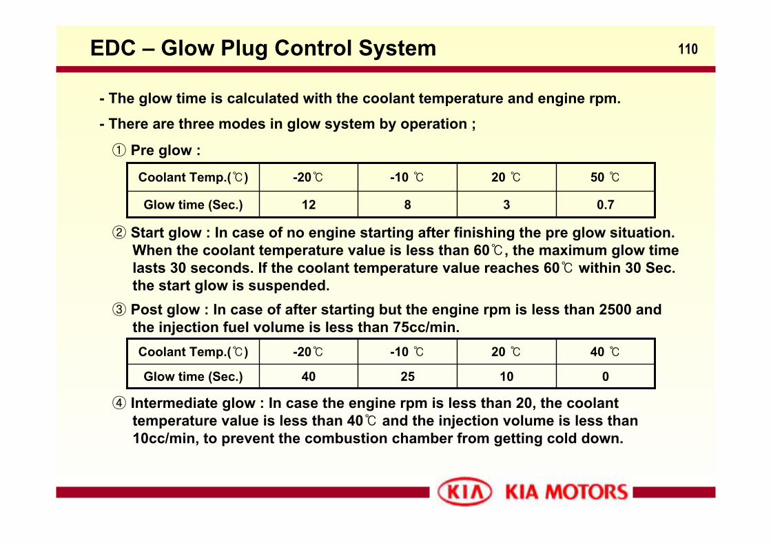
110
- The glow time is calculated with the coolant temperature and engine rpm.
EDC – Glow Plug Control System
- There are three modes in glow system by operation ;
① Pre glow :
0.73812Glow time (Sec.)
50 20 -10 -20Coolant Temp.()
② Start glow : In case of no engine starting after finishing the pre glow situation.When the coolant temperature value is less than 60, the maximum glow timelasts 30 seconds. If the coolant temperature value reaches 60 within 30 Sec.the start glow is suspended.
③ Post glow : In case of after starting but the engine rpm is less than 2500 andthe injection fuel volume is less than 75cc/min.
0102540Glow time (Sec.)
40 20 -10 -20Coolant Temp.()
④ Intermediate glow : In case the engine rpm is less than 20, the coolant temperature value is less than 40 and the injection volume is less than10cc/min, to prevent the combustion chamber from getting cold down.
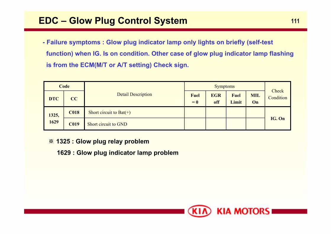
111
- Failure symptoms : Glow plug indicator lamp only lights on briefly (self-test
function) when IG. Is on condition. Other case of glow plug indicator lamp flashing
is from the ECM(M/T or A/T setting) Check sign.
EDC – Glow Plug Control System
IG. OnShort circuit to Bat(+)C0181325,
1629
Fuel Limit
Short circuit to GNDC019
MILOn
EGRoff
Fuel= 0
CCDTC
CheckCondition
Symptoms
Detail Description
Code
※ 1325 : Glow plug relay problem
1629 : Glow plug indicator lamp problem
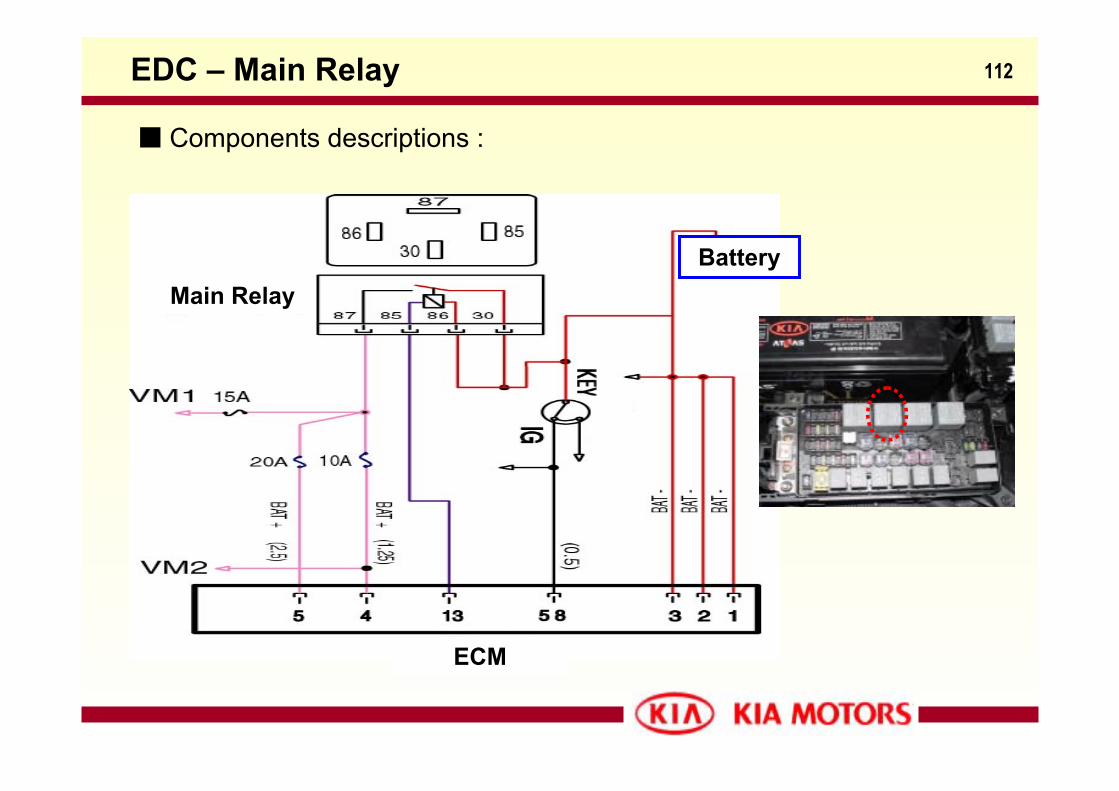
112EDC – Main Relay
Components descriptions :
Main RelayBattery
ECM
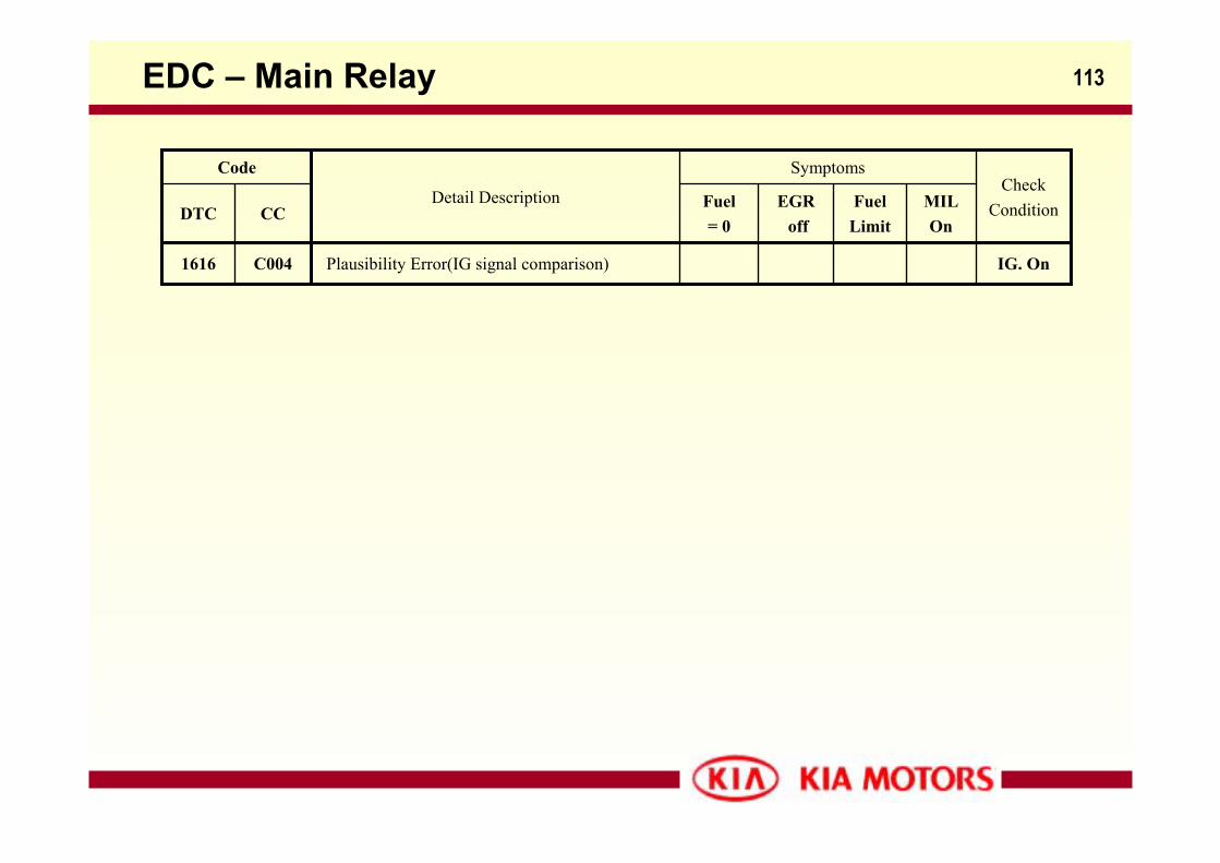
113EDC – Main Relay
IG. OnPlausibility Error(IG signal comparison)C0041616
Fuel Limit
MILOn
EGRoff
Fuel= 0
CCDTC
CheckCondition
Symptoms
Detail Description
Code
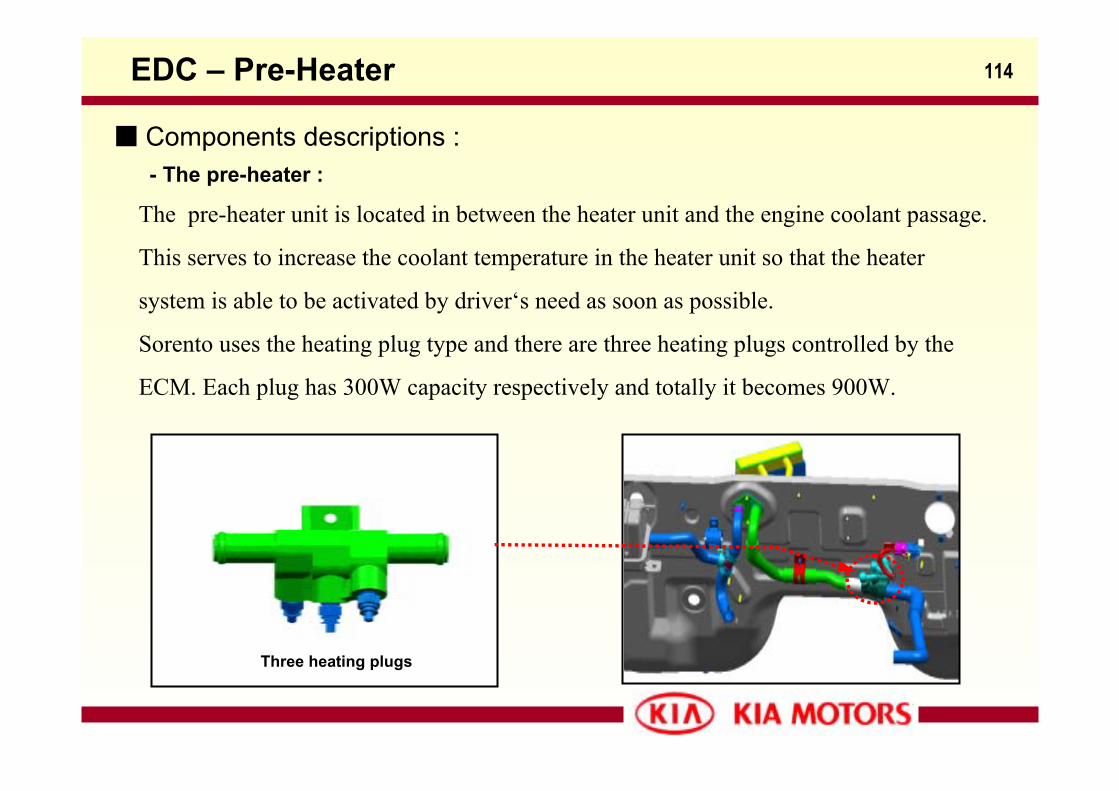
114EDC – Pre-Heater
Three heating plugs
The pre-heater unit is located in between the heater unit and the engine coolant passage.
This serves to increase the coolant temperature in the heater unit so that the heater
system is able to be activated by driver‘s need as soon as possible.
Sorento uses the heating plug type and there are three heating plugs controlled by the
ECM. Each plug has 300W capacity respectively and totally it becomes 900W.
Components descriptions : - The pre-heater :
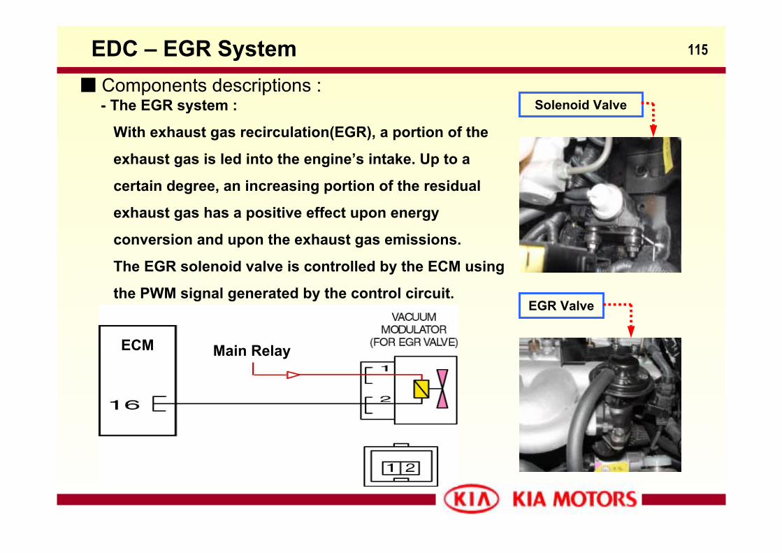
115EDC – EGR System
Main RelayECM
EGR Valve
Solenoid Valve Components descriptions :
- The EGR system :
With exhaust gas recirculation(EGR), a portion of the
exhaust gas is led into the engine’s intake. Up to a
certain degree, an increasing portion of the residual
exhaust gas has a positive effect upon energy
conversion and upon the exhaust gas emissions.
The EGR solenoid valve is controlled by the ECM using
the PWM signal generated by the control circuit.
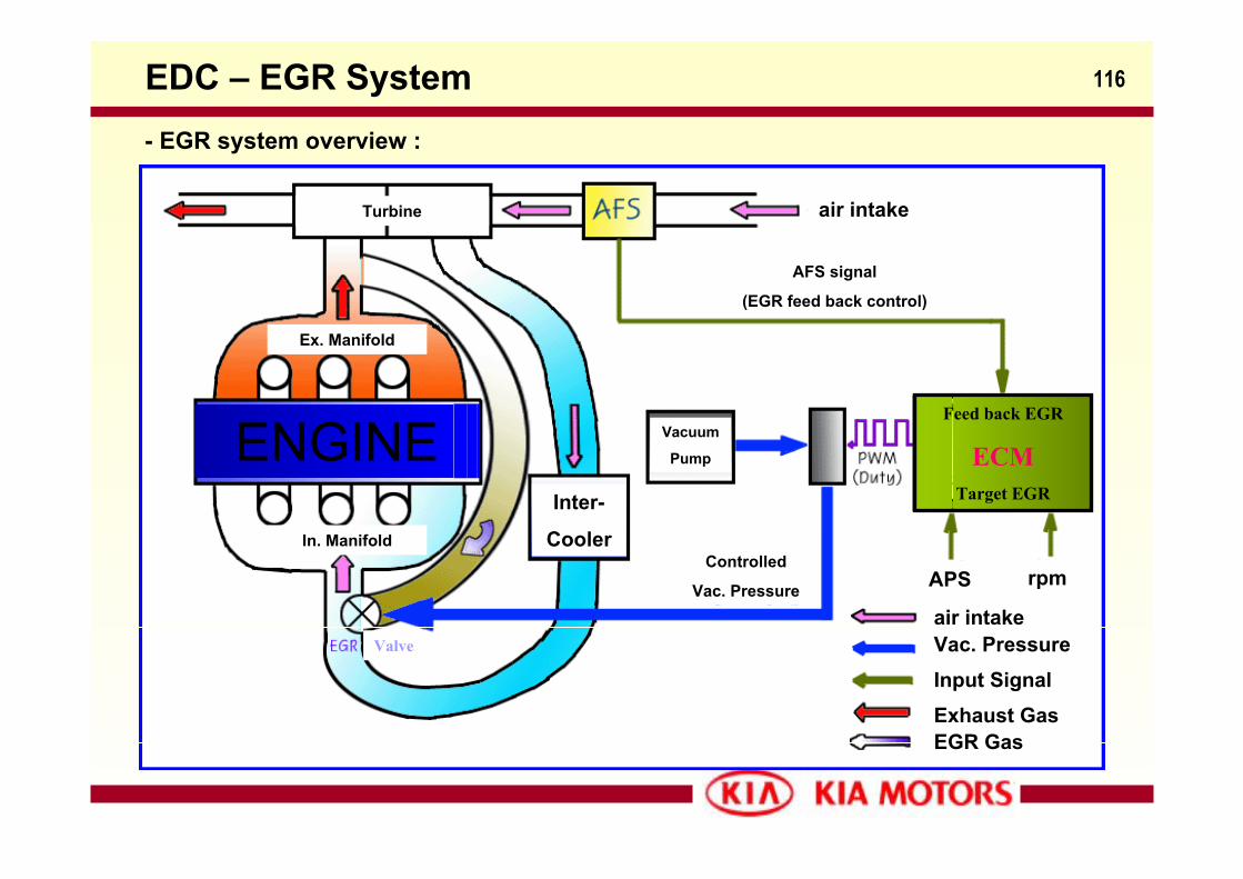
116EDC – EGR System
air intakeTurbine
Ex. Manifold
In. Manifold
ENGINEInter-
Cooler
Vacuum
Pump
AFS signal
(EGR feed back control)
Feed back EGR
ECMTarget EGR
APS rpmControlled
Vac. Pressureair intakeVac. PressureInput SignalExhaust GasEGR Gas
Valve
- EGR system overview :
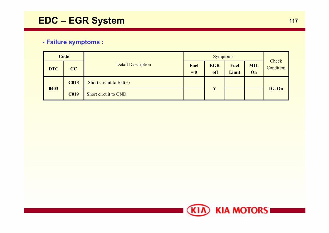
117
- Failure symptoms :
EDC – EGR System
IG. OnYShort circuit to Bat(+)C018
0403
Fuel Limit
Short circuit to GNDC019
MILOn
EGRoff
Fuel= 0
CCDTC
CheckCondition
Symptoms
Detail Description
Code
118
Engine
Sigma(Σ) 3.5ℓ Eng.
119
Contents
- Sigma(Σ) Engine Hardware
- Sigma(Σ) Engine Management System
Sigma(Σ) 3.5ℓ Eng. - Contents
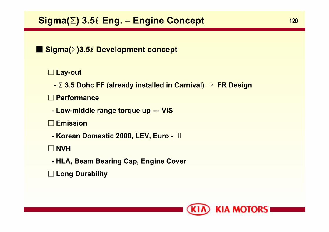
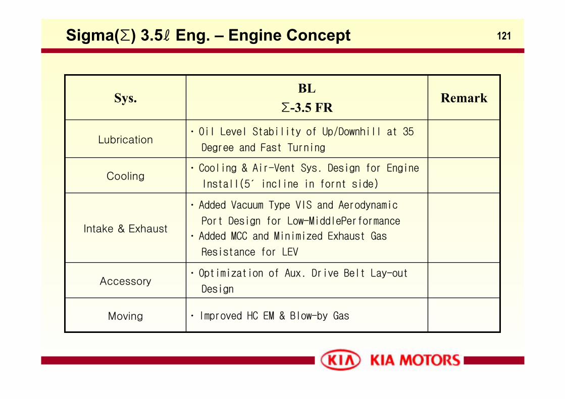
120Sigma(Σ) 3.5ℓ Eng. – Engine Concept
Sigma(Σ)3.5ℓ Development concept
Lay-out
- Σ 3.5 Dohc FF (already installed in Carnival) → FR Design
Performance
- Low-middle range torque up --- VIS
Emission
- Korean Domestic 2000, LEV, Euro - Ⅲ
NVH
- HLA, Beam Bearing Cap, Engine Cover
Long Durability
121
· Optimization of Aux. Drive Belt Lay-out
DesignAccessory
· Improved HC EM & Blow-by GasMoving
· Added Vacuum Type VIS and Aerodynamic
Port Design for Low-MiddlePerformance
· Added MCC and Minimized Exhaust Gas
Resistance for LEV
Intake & Exhaust
· Cooling & Air-Vent Sys. Design for Engine
Install(5′ incline in fornt side)Cooling
· Oil Level Stability of Up/Downhill at 35
Degree and Fast TurningLubrication
RemarkBL
Σ-3.5 FRSys.
Sigma(Σ) 3.5ℓ Eng. – Engine Concept
122
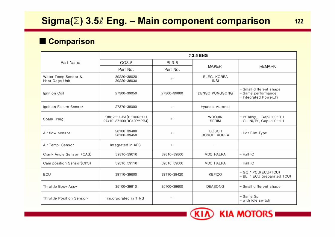
GQ3.5 BL3.5
Part No. Part No.
Water Temp Sensor & Heat Gage Unit
39220-3802039220-38030
←ELEC. KOREA
INSI
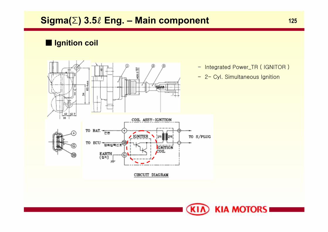
Ignition Coil 27300-39050 27300-39800 DENSO PUNGSONG- Small different shape- Same performance- Integrated Power_Tr
Ignition Failure Sensor 27370-38000 ← Hyundai Autonet
Spark Plug18817-11051(PFR5N-11)
27410-37100(RC10PYPB4)←
WOOJINSERIM
- Pt alloy, Gap: 1.0~1.1- Cu-Ni/Pt, Gap: 1.0~1.1
Air flow sensor28100-3940028100-39450
←BOSCH
BOSCH KOREA- Hot Film Type
Air Temp. Sensor Integrated in AFS ← -
Crank Angle Sensor (CAS) 39310-39010 39310-39800 VDO HALRA - Hall IC
Cam position Sensor(CPS) 39310-39110 39318-39800 VDO HALRA - Hall IC
ECU 39110-39600 39110-39420 KEFICO- GQ : PCU(ECU+TCU)- BL : ECU (separated TCU)
Throttle Body Assy 35100-39610 35100-39600 DEASONG - Small different shape
Throttle Position Sensor* incorporated in TH/B ←- Same Sp- with idle switch
Part Name
Σ3.5 ENG
MAKER REMARK
Sigma(Σ) 3.5ℓ Eng. – Main component comparison
Comparison
123
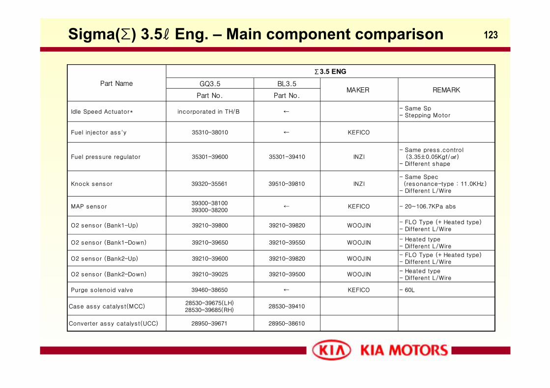
GQ3.5 BL3.5
Part No. Part No.
Idle Speed Actuator* incorporated in TH/B ←- Same Sp- Stepping Motor
Fuel injector ass'y 35310-38010 ← KEFICO
Fuel pressure regulator 35301-39600 35301-39410 INZI- Same press.control (3.35±0.05Kgf/)- Different shape
Knock sensor 39320-35561 39510-39810 INZI- Same Spec (resonance-type : 11.0KHz )- Different L/Wire
MAP sensor39300-3810039300-38200
← KEFICO - 20~106.7KPa abs
O2 sensor (Bank1-Up) 39210-39800 39210-39820 WOOJIN- FLO Type (+ Heated type)- Different L/Wire
O2 sensor (Bank1-Down) 39210-39650 39210-39550 WOOJIN- Heated type- Different L/Wire
O2 sensor (Bank2-Up) 39210-39600 39210-39820 WOOJIN- FLO Type (+ Heated type)- Different L/Wire
O2 sensor (Bank2-Down) 39210-39025 39210-39500 WOOJIN- Heated type- Different L/Wire
Purge solenoid valve 39460-38650 ← KEFICO - 60L
Case assy catalyst(MCC)28530-39675(LH)28530-39685(RH)
28530-39410
Converter assy catalyst(UCC) 28950-39671 28950-38610
Part Name
Σ3.5 ENG
MAKER REMARK
Sigma(Σ) 3.5ℓ Eng. – Main component comparison
124
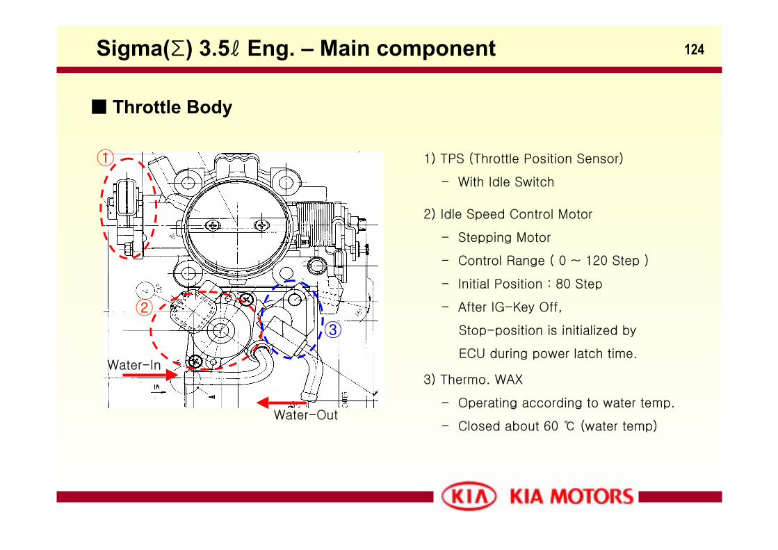
1) TPS (Throttle Position Sensor)
- With Idle Switch
2) Idle Speed Control Motor
- Stepping Motor
- Control Range ( 0 ~ 120 Step )
- Initial Position : 80 Step
- After IG-Key Off,
Stop-position is initialized by
ECU during power latch time.
3) Thermo. WAX
- Operating according to water temp.
- Closed about 60 (water temp)
Water-In
Water-Out
①
②③
Sigma(Σ) 3.5ℓ Eng. – Main component
Throttle Body
125
- Integrated Power_TR ( IGNITOR )
- 2- Cyl. Simultaneous Ignition
Sigma(Σ) 3.5ℓ Eng. – Main component
Ignition coil
126Sigma(Σ) 3.5ℓ Eng. – Main component
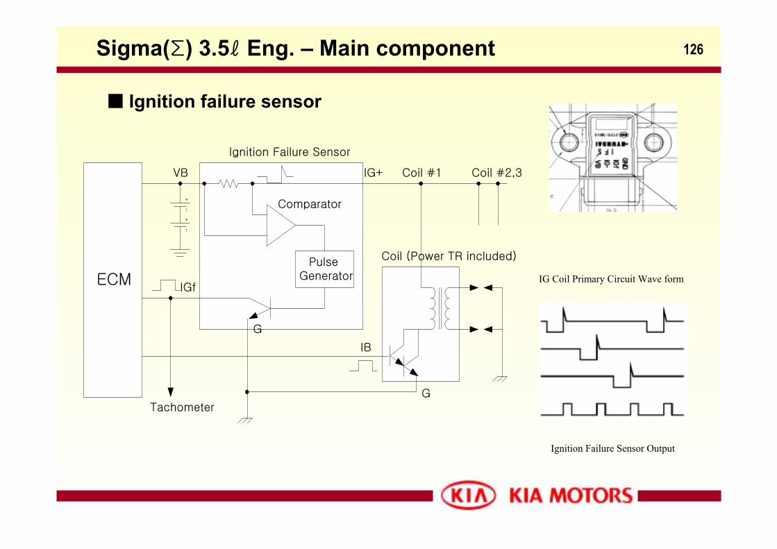
Ignition failure sensor
ECMPulse
Generator
VB
Ignition Failure Sensor
Comparator
G
Tachometer
IGf
IB
G
Coil (Power TR included)
IG+ Coil #1 Coil #2,3
IG Coil Primary Circuit Wave form
Ignition Failure Sensor Output
127
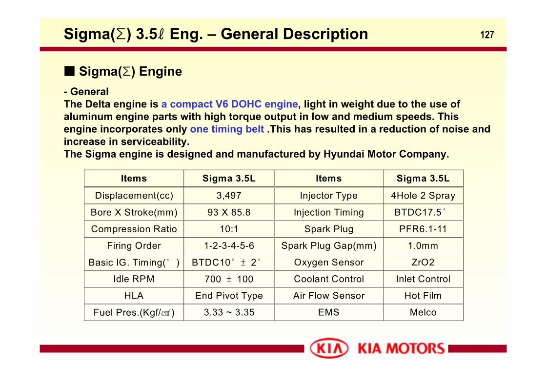
Sigma(Σ) Engine- GeneralThe Delta engine is a compact V6 DOHC engine, light in weight due to the use of aluminum engine parts with high torque output in low and medium speeds. This engine incorporates only one timing belt .This has resulted in a reduction of noise and increase in serviceability.The Sigma engine is designed and manufactured by Hyundai Motor Company.
Items Sigma 3.5L Items Sigma 3.5L
Displacement(cc) 3,497 Injector Type 4Hole 2 Spray
Bore X Stroke(mm) 93 X 85.8 Injection Timing BTDC17.5˚
Compression Ratio 10:1 Spark Plug PFR6.1-11
Firing Order 1-2-3-4-5-6 Spark Plug Gap(mm) 1.0mm
Basic IG. Timing(˚ ) BTDC10˚ ± 2˚ Oxygen Sensor ZrO2
Idle RPM 700 ± 100 Coolant Control Inlet Control
HLA End Pivot Type Air Flow Sensor Hot Film
Fuel Pres.(Kgf/) 3.33 ~ 3.35 EMS Melco
Sigma(Σ) 3.5ℓ Eng. – General Description
128
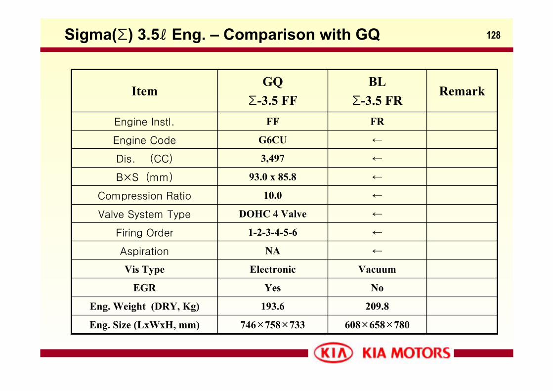
NoYesEGR
←DOHC 4 ValveValve System Type
FRFFEngine Instl.
←NAAspiration
VacuumElectronicVis Type
209.8193.6Eng. Weight (DRY, Kg)
608×658×780746×758×733Eng. Size (LxWxH, mm)
←1-2-3-4-5-6Firing Order
←10.0Compression Ratio
←93.0 x 85.8B×S (mm)
←3,497Dis. (CC)
←G6CUEngine Code
RemarkBL
Σ-3.5 FRGQ
Σ-3.5 FFItem
Sigma(Σ) 3.5ℓ Eng. – Comparison with GQ
129
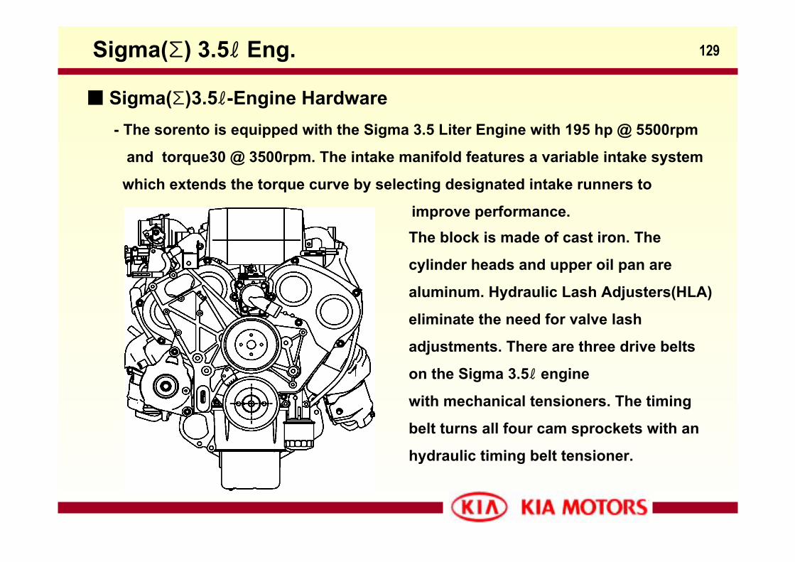
Sigma(Σ)3.5ℓ-Engine Hardware
Sigma(Σ) 3.5ℓ Eng.
- The sorento is equipped with the Sigma 3.5 Liter Engine with 195 hp @ 5500rpm
and torque30 @ 3500rpm. The intake manifold features a variable intake system
which extends the torque curve by selecting designated intake runners to
improve performance. The block is made of cast iron. The
cylinder heads and upper oil pan are
aluminum. Hydraulic Lash Adjusters(HLA)
eliminate the need for valve lash
adjustments. There are three drive belts
on the Sigma 3.5ℓ engine
with mechanical tensioners. The timing
belt turns all four cam sprockets with an
hydraulic timing belt tensioner.
130
0
50
100
150
200
250
1000 2000 3000 4000 5000 6000 7000
Engine Speed [rpm]
Pow
er [p
s]
.
18.0
22.0
26.0
30.0
34.0
Torq
ue [
Kg.m
] .
BL GQ
BL
XG
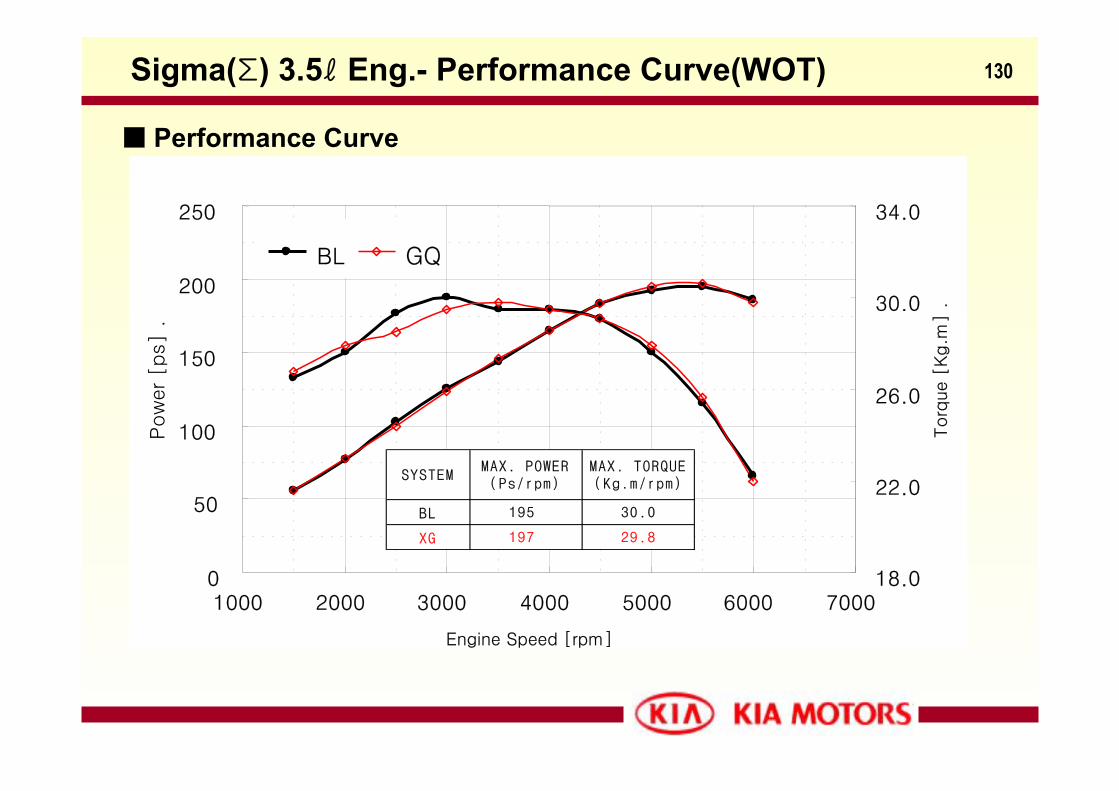
SYSTEMMAX. POWER(Ps/rpm)
MAX. TORQUE(Kg.m/rpm)
195
197
30.0
29.8
Sigma(Σ) 3.5ℓ Eng.- Performance Curve(WOT)
Performance Curve
131
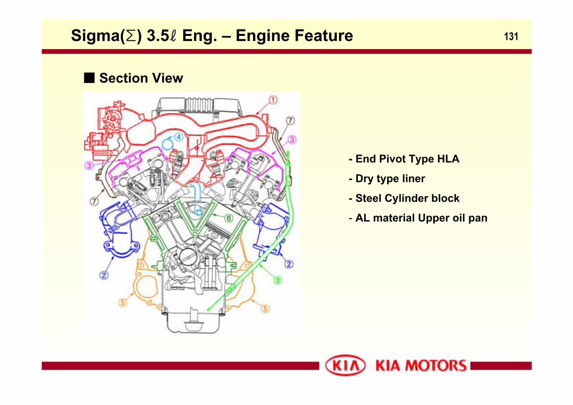
Section View
- End Pivot Type HLA
- Dry type liner
- Steel Cylinder block
- AL material Upper oil pan
Sigma(Σ) 3.5ℓ Eng. – Engine Feature
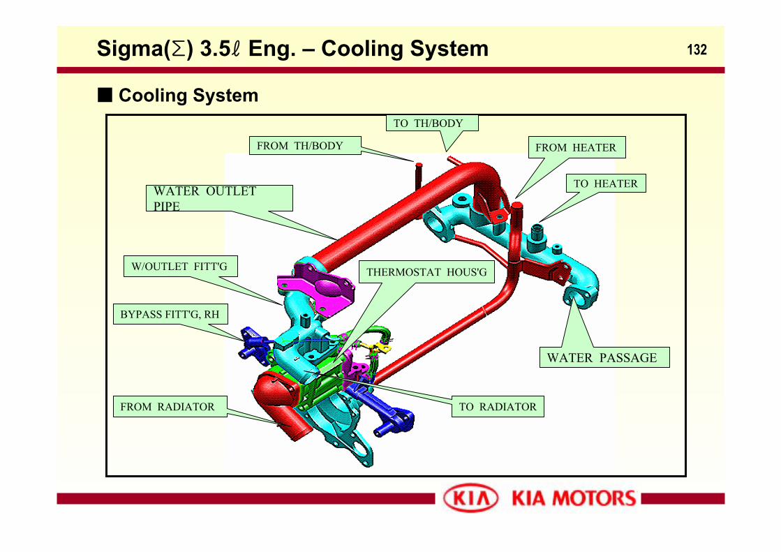
132Sigma(Σ) 3.5ℓ Eng. – Cooling System
WATER PASSAGE
WATER OUTLET PIPE
W/OUTLET FITT'G THERMOSTAT HOUS'G
FROM HEATER
TO HEATER
FROM TH/BODY
TO TH/BODY
BYPASS FITT'G, RH
FROM RADIATOR TO RADIATOR
Cooling System
133
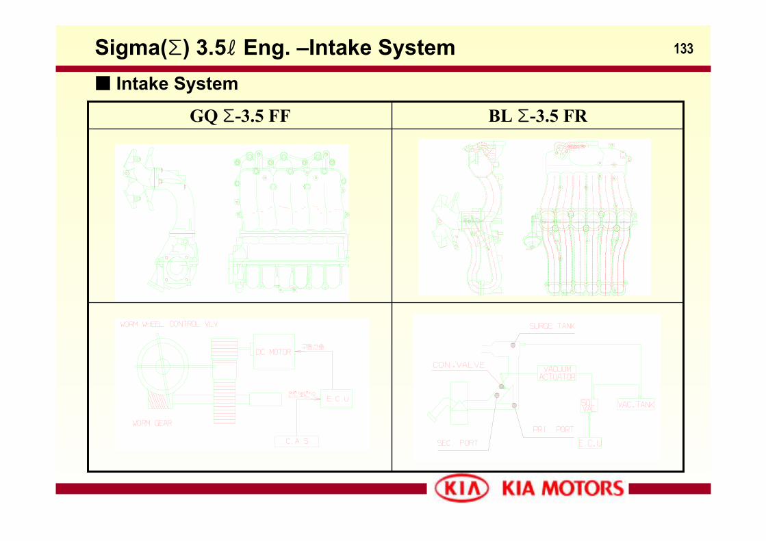
BL Σ-3.5 FRGQ Σ-3.5 FF
Sigma(Σ) 3.5ℓ Eng. –Intake System Intake System
134
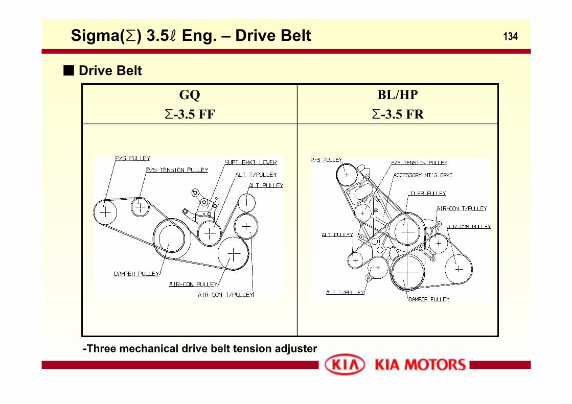
Drive Belt
-Three mechanical drive belt tension adjuster
Sigma(Σ) 3.5ℓ Eng. – Drive Belt
BL/HPΣ-3.5 FR
GQΣ-3.5 FF
135
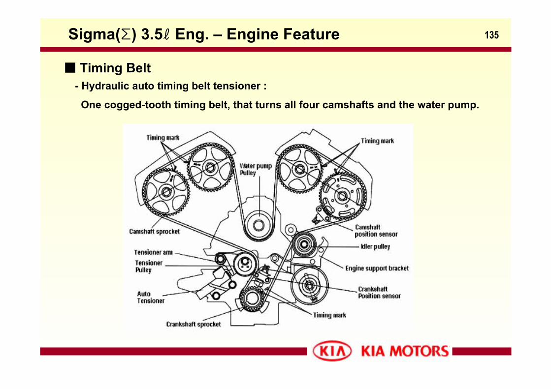
Timing Belt- Hydraulic auto timing belt tensioner :
One cogged-tooth timing belt, that turns all four camshafts and the water pump.
Sigma(Σ) 3.5ℓ Eng. – Engine Feature
136
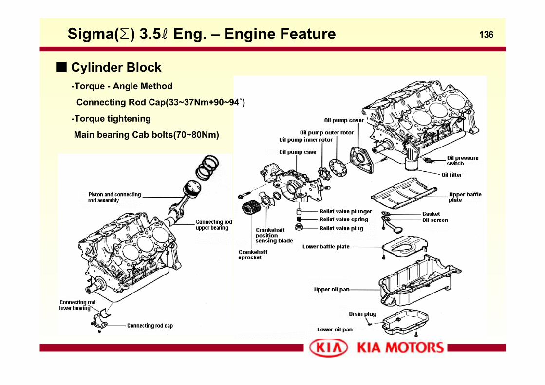
Cylinder Block
Sigma(Σ) 3.5ℓ Eng. – Engine Feature
-Torque - Angle Method
Connecting Rod Cap(33~37Nm+90~94˚)
-Torque tightening
Main bearing Cab bolts(70~80Nm)
137
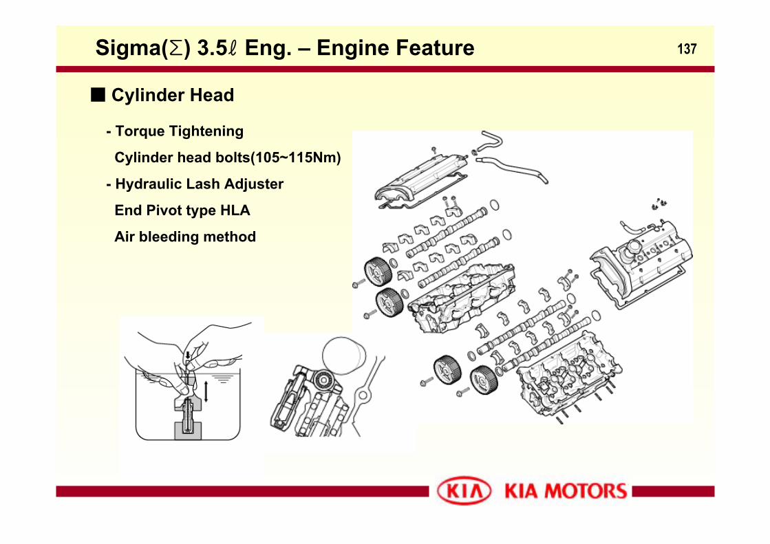
Cylinder Head
- Torque Tightening
Cylinder head bolts(105~115Nm)
- Hydraulic Lash Adjuster
End Pivot type HLA
Air bleeding method
Sigma(Σ) 3.5ℓ Eng. – Engine Feature
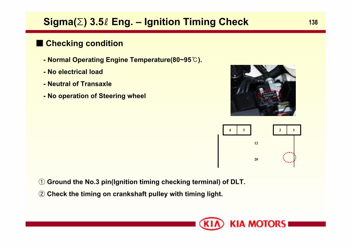
138
Checking condition
- Normal Operating Engine Temperature(80~95).
- No electrical load
- Neutral of Transaxle
- No operation of Steering wheel
① Ground the No.3 pin(Ignition timing checking terminal) of DLT.
② Check the timing on crankshaft pulley with timing light.
Sigma(Σ) 3.5ℓ Eng. – Ignition Timing Check
20
12
34 12
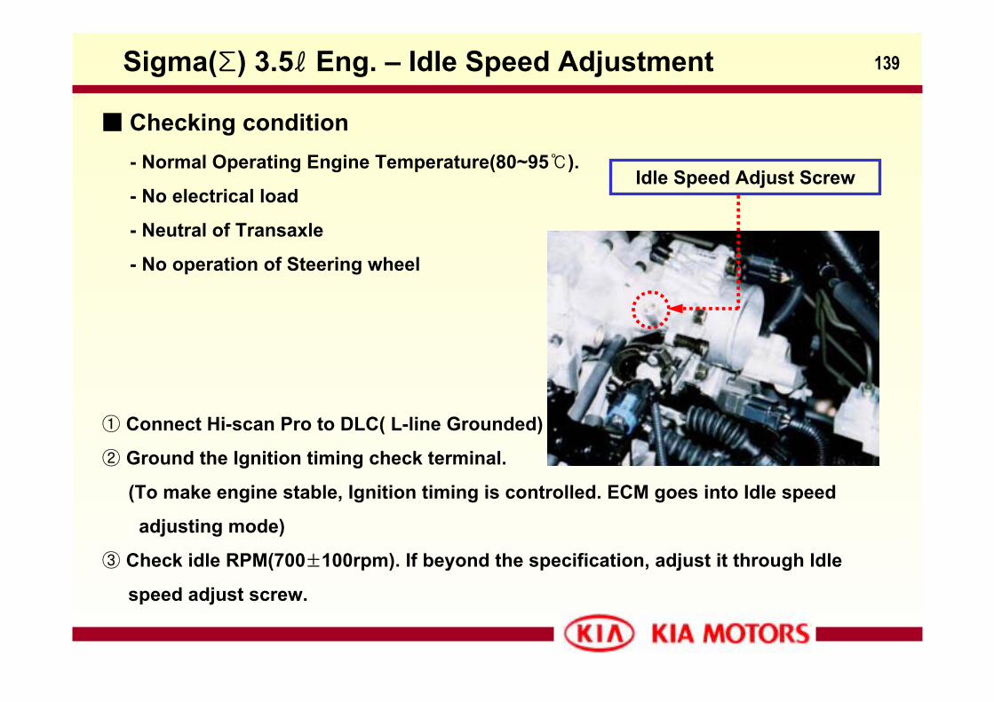
139
Checking condition- Normal Operating Engine Temperature(80~95).
- No electrical load
- Neutral of Transaxle
- No operation of Steering wheel
① Connect Hi-scan Pro to DLC( L-line Grounded)
② Ground the Ignition timing check terminal.
(To make engine stable, Ignition timing is controlled. ECM goes into Idle speed
adjusting mode)
③ Check idle RPM(700±100rpm). If beyond the specification, adjust it through Idle
speed adjust screw.
Sigma(Σ) 3.5ℓ Eng. – Idle Speed Adjustment
Idle Speed Adjust Screw
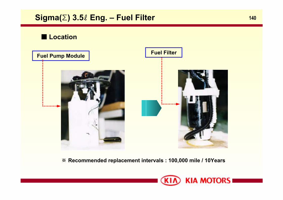
140
Location
※ Recommended replacement intervals : 100,000 mile / 10Years
Sigma(Σ) 3.5ℓ Eng. – Fuel Filter
Fuel Pump Module Fuel Filter
141
Sigma(∑)-engineEngine Management System
Sigma(Σ) 3.5ℓ Eng. – EMS
142
Contents- System Configuration
- System Description
- ECM Input/Output
- OBD2 Functions
- Diagnostic Trouble Code
- ECM Wiring circuit
Sigma(Σ) 3.5ℓ Eng. – Contents
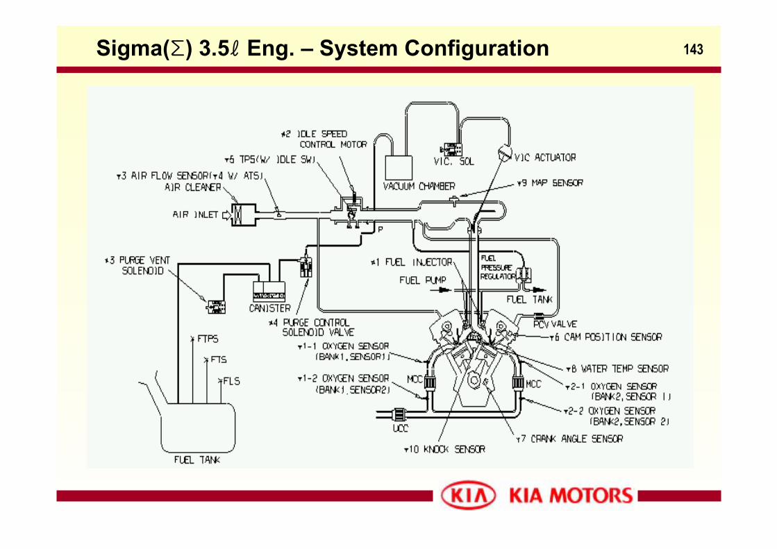
143Sigma(Σ) 3.5ℓ Eng. – System Configuration
144Sigma(Σ) 3.5ℓ Eng. – System Configuration
General descriptions : - The Sorento utilizes a Mitsubishi Electronics Company Engine Management System
(MELCO). The MELCO system features a single 32 bit Powertrain Control Module
(PCM) to control engine management as well as all automatic transaxle functions.
Serial communication is used to transmit data between the engine and transaxle
sections of the PCM. A sequential Multiport Fuel Injection system (SFI) is
incorporated, along with a distributorless ignition system.
- The ignition system of Sorento Sigma 3.5ℓ engine is very similar to previous
ignition systems used on Kia vehicles since 1998 with the exception of having an
additional coil for the 2 extra cylinders and and ignition failure sensor.
- Engine management system monitoring functions are conducted in compliance
with OBD-Ⅱ regulations. An EGR system is not employed in the Sorento.
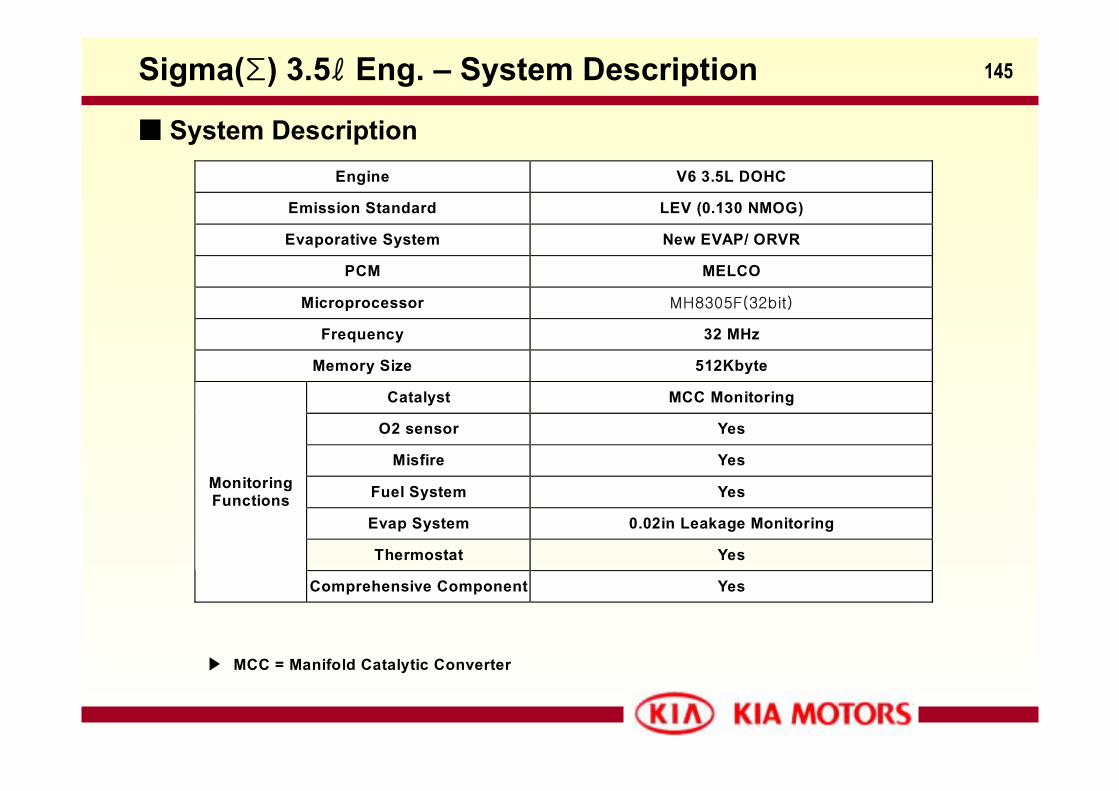
145
Engine V6 3.5L DOHC
Emission Standard LEV (0.130 NMOG)
Evaporative System New EVAP/ ORVR
PCM MELCO
Microprocessor MH8305F(32bit)
Frequency 32 MHz
Memory Size 512Kbyte
Catalyst MCC Monitoring
O2 sensor Yes
Misfire Yes
Fuel System Yes
Evap System 0.02in Leakage Monitoring
Thermostat Yes
MonitoringFunctions
Comprehensive Component Yes
MCC = Manifold Catalytic Converter
System Description
Sigma(Σ) 3.5ℓ Eng. – System Description
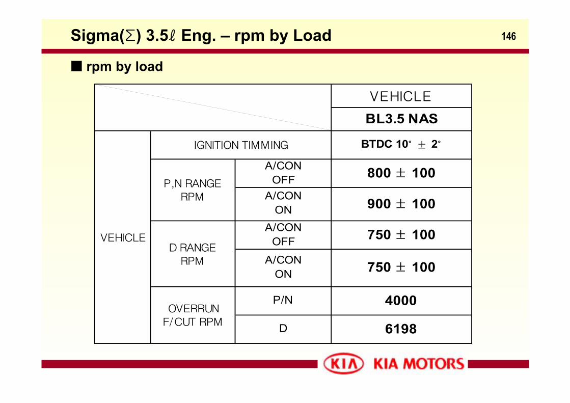
146
BL3.5 NASVEHICLE
D RANGERPM
A/CONOFF 750 ± 100
P,N RANGERPM
A/CONOFF 800 ± 100
A/CONON 900 ± 100
A/CONON 750 ± 100
OVERRUNF/CUT RPM
P/N 4000
VEHICLE
IGNITION TIMMING BTDC 10˚ ± 2˚
D 6198
Sigma(Σ) 3.5ℓ Eng. – rpm by Load
rpm by load
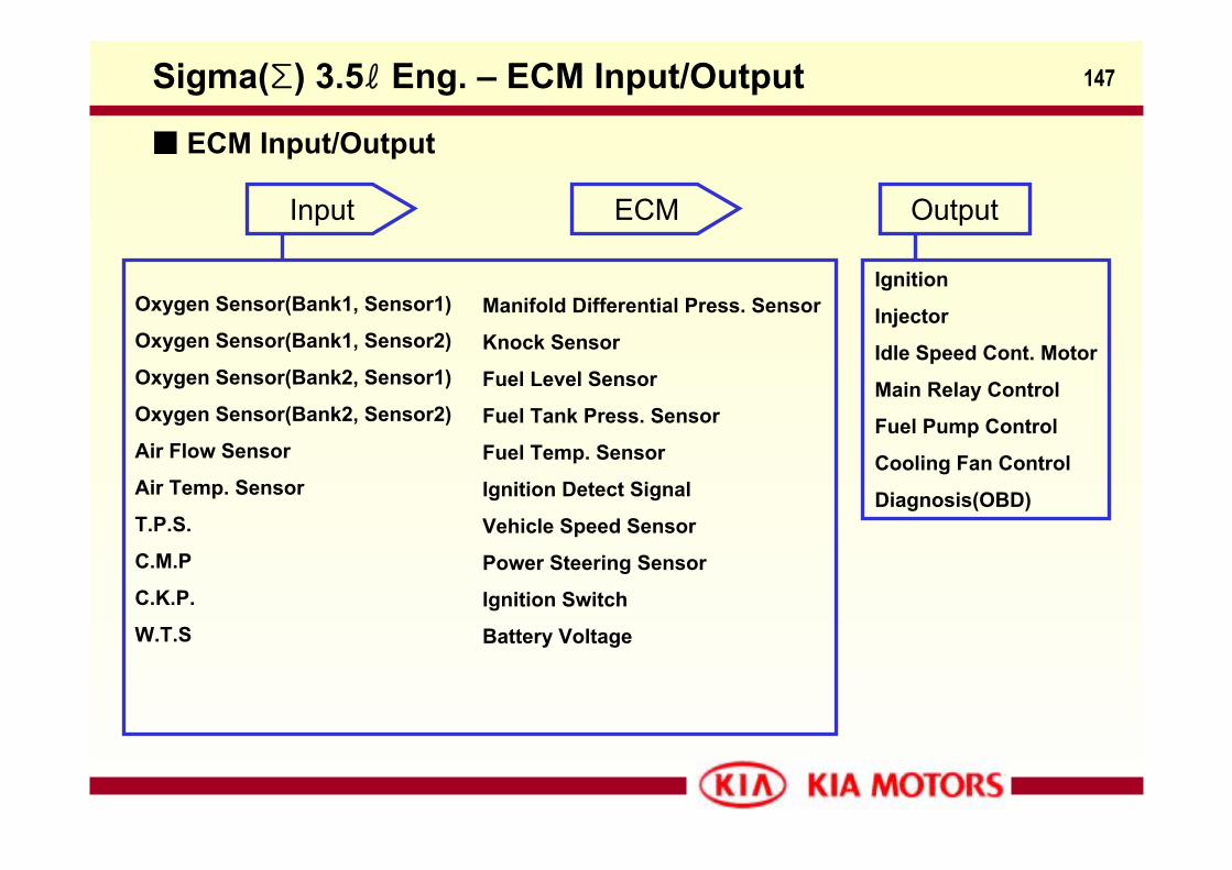
147Sigma(Σ) 3.5ℓ Eng. – ECM Input/Output
ECM Input/Output
Ignition
Injector
Idle Speed Cont. Motor
Main Relay Control
Fuel Pump Control
Cooling Fan Control
Diagnosis(OBD)
Input Output
Oxygen Sensor(Bank1, Sensor1)
Oxygen Sensor(Bank1, Sensor2)
Oxygen Sensor(Bank2, Sensor1)
Oxygen Sensor(Bank2, Sensor2)
Air Flow Sensor
Air Temp. Sensor
T.P.S.
C.M.P
C.K.P.
W.T.S
Manifold Differential Press. Sensor
Knock Sensor
Fuel Level Sensor
Fuel Tank Press. Sensor
Fuel Temp. Sensor
Ignition Detect Signal
Vehicle Speed Sensor
Power Steering Sensor
Ignition Switch
Battery Voltage
ECM
148
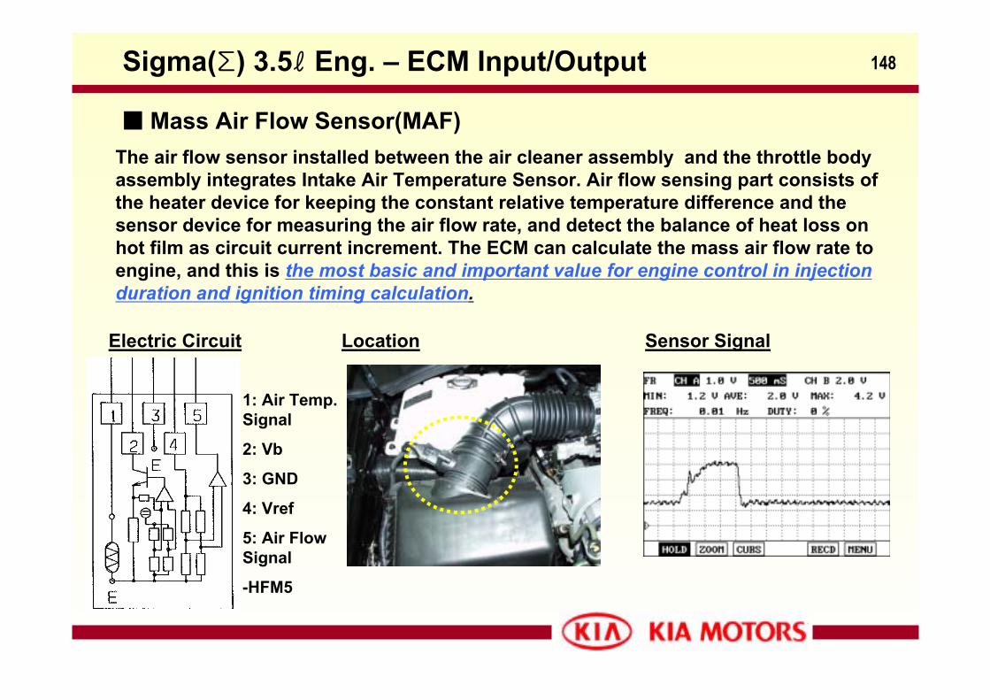
The air flow sensor installed between the air cleaner assembly and the throttle body assembly integrates Intake Air Temperature Sensor. Air flow sensing part consists of the heater device for keeping the constant relative temperature difference and the sensor device for measuring the air flow rate, and detect the balance of heat loss on hot film as circuit current increment. The ECM can calculate the mass air flow rate to engine, and this is the most basic and important value for engine control in injection duration and ignition timing calculation.
Electric Circuit
1: Air Temp. Signal
2: Vb
3: GND
4: Vref
5: Air Flow Signal
-HFM5
Sensor SignalLocation
Sigma(Σ) 3.5ℓ Eng. – ECM Input/Output
Mass Air Flow Sensor(MAF)
149
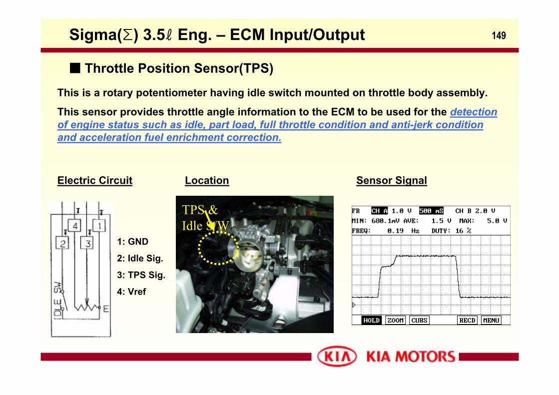
This is a rotary potentiometer having idle switch mounted on throttle body assembly.
This sensor provides throttle angle information to the ECM to be used for the detection of engine status such as idle, part load, full throttle condition and anti-jerk condition and acceleration fuel enrichment correction.
Electric Circuit Sensor Signal
1: GND
2: Idle Sig.
3: TPS Sig.
4: Vref
Location
Sigma(Σ) 3.5ℓ Eng. – ECM Input/Output
Throttle Position Sensor(TPS)
TPS & Idle S/W
150
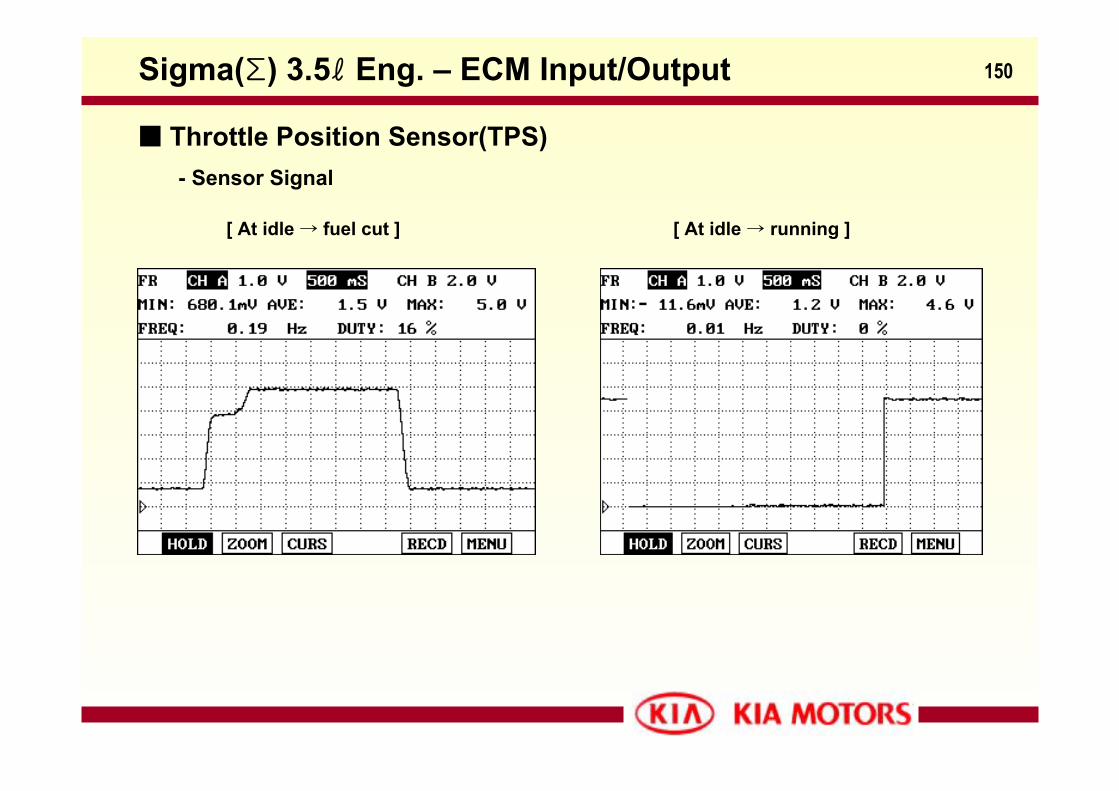
- Sensor Signal
[ At idle → fuel cut ] [ At idle → running ]
Sigma(Σ) 3.5ℓ Eng. – ECM Input/Output
Throttle Position Sensor(TPS)
151
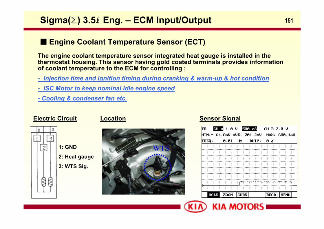
The engine coolant temperature sensor integrated heat gauge is installed in the thermostat housing. This sensor having gold coated terminals provides information of coolant temperature to the ECM for controlling ;- Injection time and ignition timing during cranking & warm-up & hot condition - ISC Motor to keep nominal idle engine speed- Cooling & condenser fan etc.
Electric Circuit
1: GND
2: Heat gauge
3: WTS Sig.
Sensor SignalLocation
Sigma(Σ) 3.5ℓ Eng. – ECM Input/Output
Engine Coolant Temperature Sensor (ECT)
WTS
152
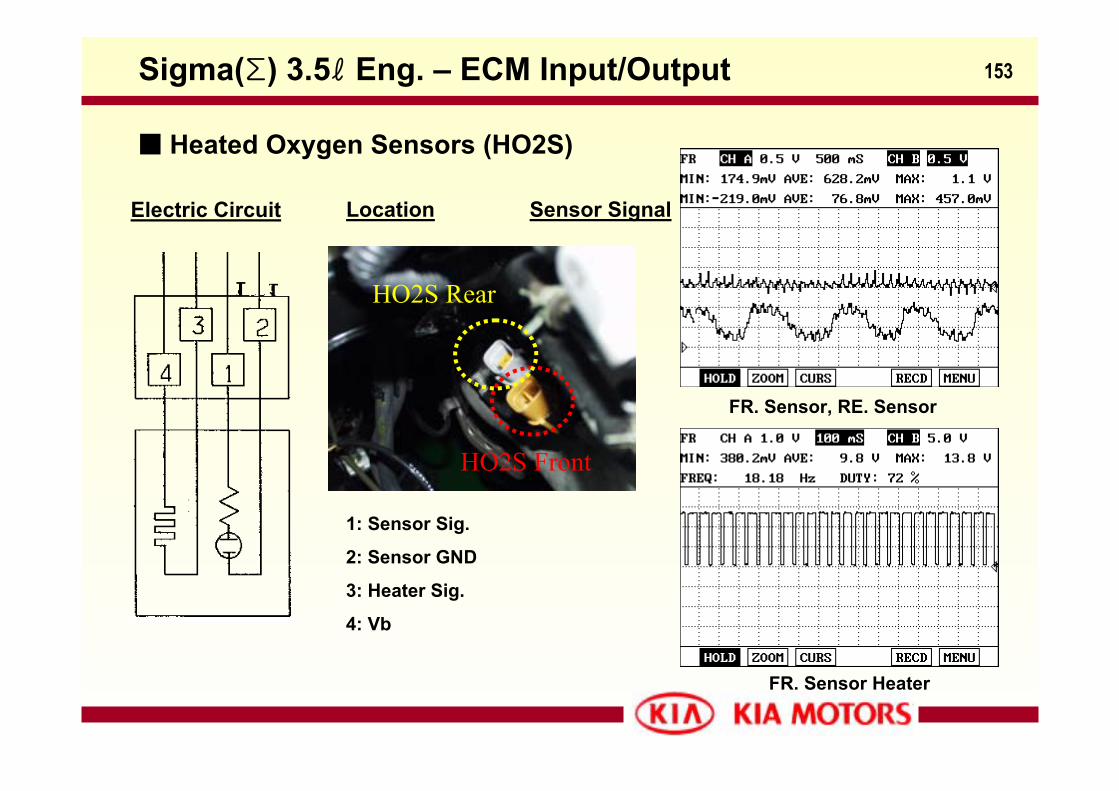
There are four O2 sensors in a vehicle, two of them are installed in the upstream and the others are installed downstream of each bank of manifold catalyst.
The O2 sensors is consists of Zirconia type sensing element and heater. The sensing element produces voltage according to the richness of exhaust gas, and this voltage to reference in ECM reflect lean or rich status.
For each bank(1/2), ECM can control the fuel injection rate separately with the feedback of each front O2 sensor signals, and the desired air/fuel ratio which provide the best conversion efficiency is achieved.
The rear O2 sensors also inform ECM of lean or rich status of exhaust gas existing the closed-coupled catalyst.
The rear O2 sensor signals are used not only for the richness correction to control NOxemission effectively but for the determination of catalyst deterioration factor to monitor the catalyst converter.
And, the O2 sensor tip temperature is controlled to 750deg.C to get reliable sensor signal output by already programed O2 heater control function.
Sigma(Σ) 3.5ℓ Eng. – ECM Input/Output
Heated Oxygen Sensors (HO2S)
153
Electric Circuit
1: Sensor Sig.
2: Sensor GND
3: Heater Sig.
4: Vb
FR. Sensor, RE. Sensor
FR. Sensor Heater
Sensor SignalLocation
Sigma(Σ) 3.5ℓ Eng. – ECM Input/Output
Heated Oxygen Sensors (HO2S)
HO2S Front
HO2S Rear
154
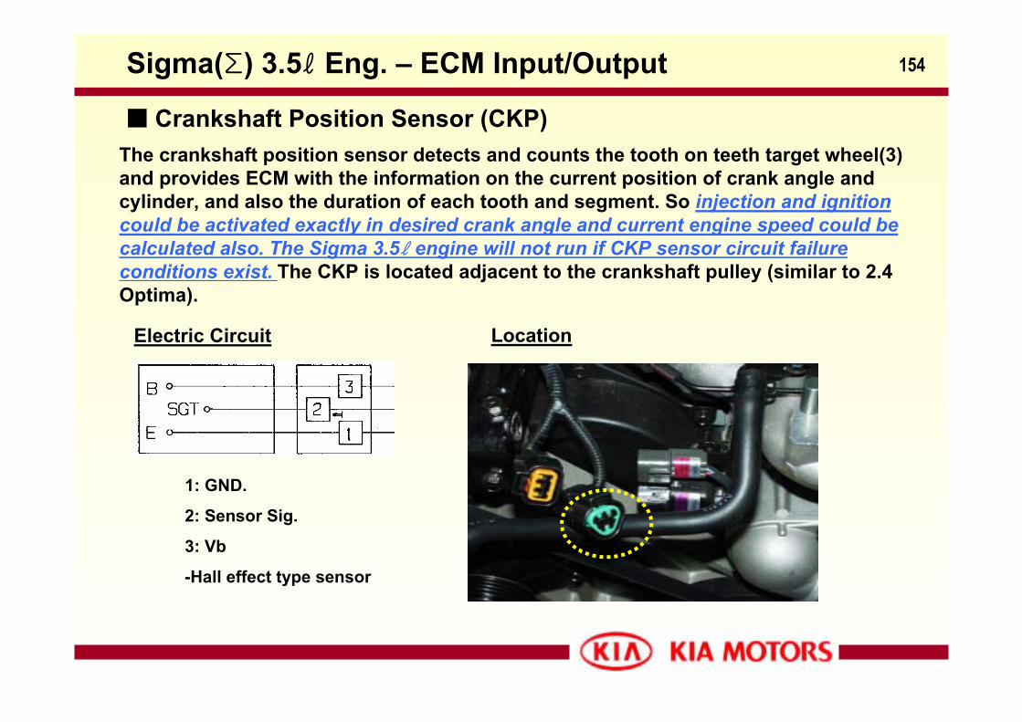
The crankshaft position sensor detects and counts the tooth on teeth target wheel(3) and provides ECM with the information on the current position of crank angle and cylinder, and also the duration of each tooth and segment. So injection and ignition could be activated exactly in desired crank angle and current engine speed could be calculated also. The Sigma 3.5ℓ engine will not run if CKP sensor circuit failure conditions exist. The CKP is located adjacent to the crankshaft pulley (similar to 2.4 Optima).
Electric Circuit
1: GND.
2: Sensor Sig.
3: Vb
-Hall effect type sensor
Location
Sigma(Σ) 3.5ℓ Eng. – ECM Input/Output
Crankshaft Position Sensor (CKP)
155
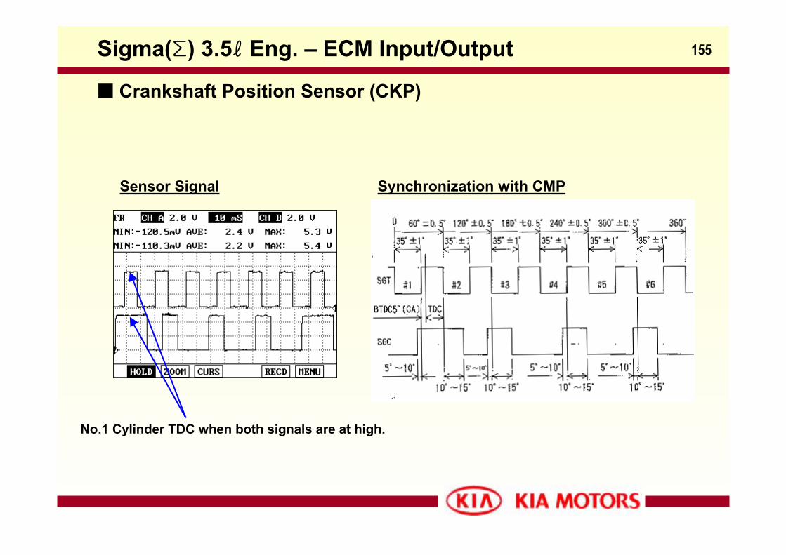
Sensor Signal Synchronization with CMP
No.1 Cylinder TDC when both signals are at high.
Sigma(Σ) 3.5ℓ Eng. – ECM Input/Output
Crankshaft Position Sensor (CKP)
156
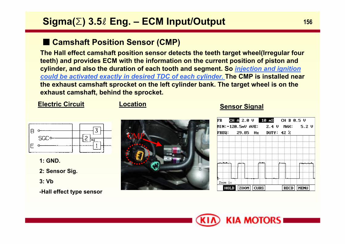
The Hall effect camshaft position sensor detects the teeth target wheel(Irregular four teeth) and provides ECM with the information on the current position of piston and cylinder, and also the duration of each tooth and segment. So injection and ignition could be activated exactly in desired TDC of each cylinder. The CMP is installed near the exhaust camshaft sprocket on the left cylinder bank. The target wheel is on the exhaust camshaft, behind the sprocket.
Electric Circuit
1: GND.
2: Sensor Sig.
3: Vb
-Hall effect type sensor
Location Sensor Signal
Sigma(Σ) 3.5ℓ Eng. – ECM Input/Output
Camshaft Position Sensor (CMP)
CMP
157
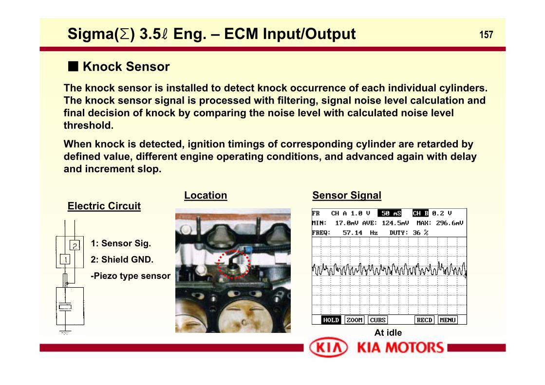
Electric Circuit
The knock sensor is installed to detect knock occurrence of each individual cylinders. The knock sensor signal is processed with filtering, signal noise level calculation and final decision of knock by comparing the noise level with calculated noise level threshold.
When knock is detected, ignition timings of corresponding cylinder are retarded by defined value, different engine operating conditions, and advanced again with delay and increment slop.
Location Sensor Signal
1: Sensor Sig.
2: Shield GND.
-Piezo type sensor
At idle
Sigma(Σ) 3.5ℓ Eng. – ECM Input/Output
Knock Sensor
158
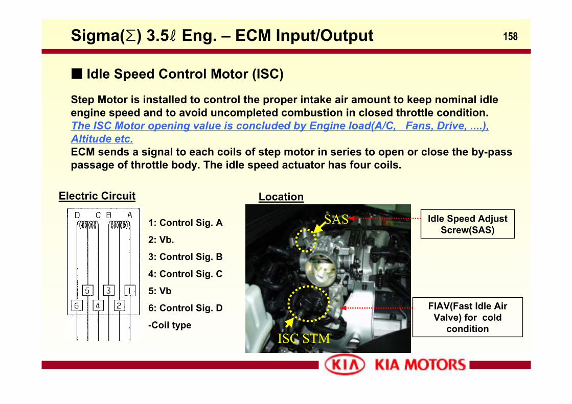
Step Motor is installed to control the proper intake air amount to keep nominal idle engine speed and to avoid uncompleted combustion in closed throttle condition.The ISC Motor opening value is concluded by Engine load(A/C, Fans, Drive, ....), Altitude etc.ECM sends a signal to each coils of step motor in series to open or close the by-pass passage of throttle body. The idle speed actuator has four coils.
Electric Circuit
Idle Speed Adjust Screw(SAS)
FIAV(Fast Idle Air Valve) for cold
condition
1: Control Sig. A
2: Vb.
3: Control Sig. B
4: Control Sig. C
5: Vb
6: Control Sig. D
-Coil type
Location
Sigma(Σ) 3.5ℓ Eng. – ECM Input/Output
Idle Speed Control Motor (ISC)
ISC STM
SAS
159
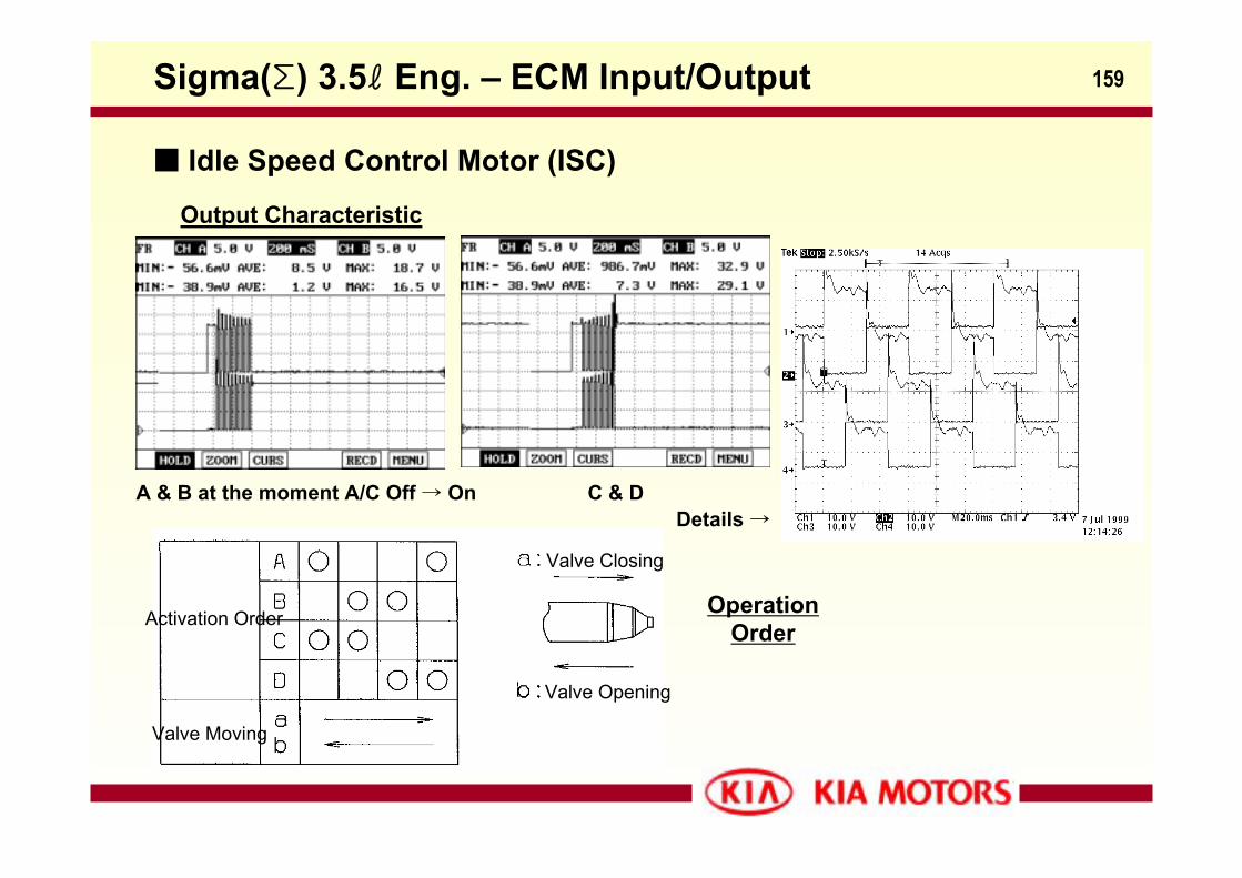
Output Characteristic
A & B at the moment A/C Off → On C & D Details →
Operation Order
Valve Closing
Valve Opening
Activation Order
Valve Moving
Sigma(Σ) 3.5ℓ Eng. – ECM Input/Output
Idle Speed Control Motor (ISC)
160
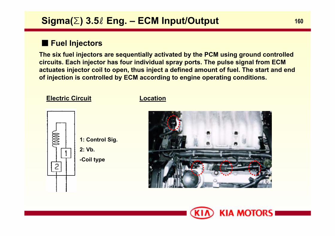
The six fuel injectors are sequentially activated by the PCM using ground controlled circuits. Each injector has four individual spray ports. The pulse signal from ECM actuates injector coil to open, thus inject a defined amount of fuel. The start and end of injection is controlled by ECM according to engine operating conditions.
Electric Circuit
1: Control Sig.
2: Vb.
-Coil type
Location
Sigma(Σ) 3.5ℓ Eng. – ECM Input/Output
Fuel Injectors
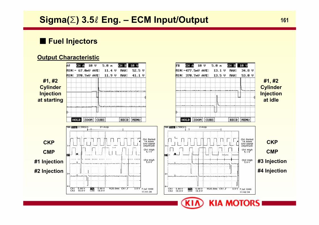
161
Output Characteristic
#1, #2 Cylinder Injection
at starting
#1, #2 Cylinder Injection
at idle
CKP
CMP
#1 Injection
#2 Injection
CKP
CMP
#3 Injection
#4 Injection
Sigma(Σ) 3.5ℓ Eng. – ECM Input/Output
Fuel Injectors
162
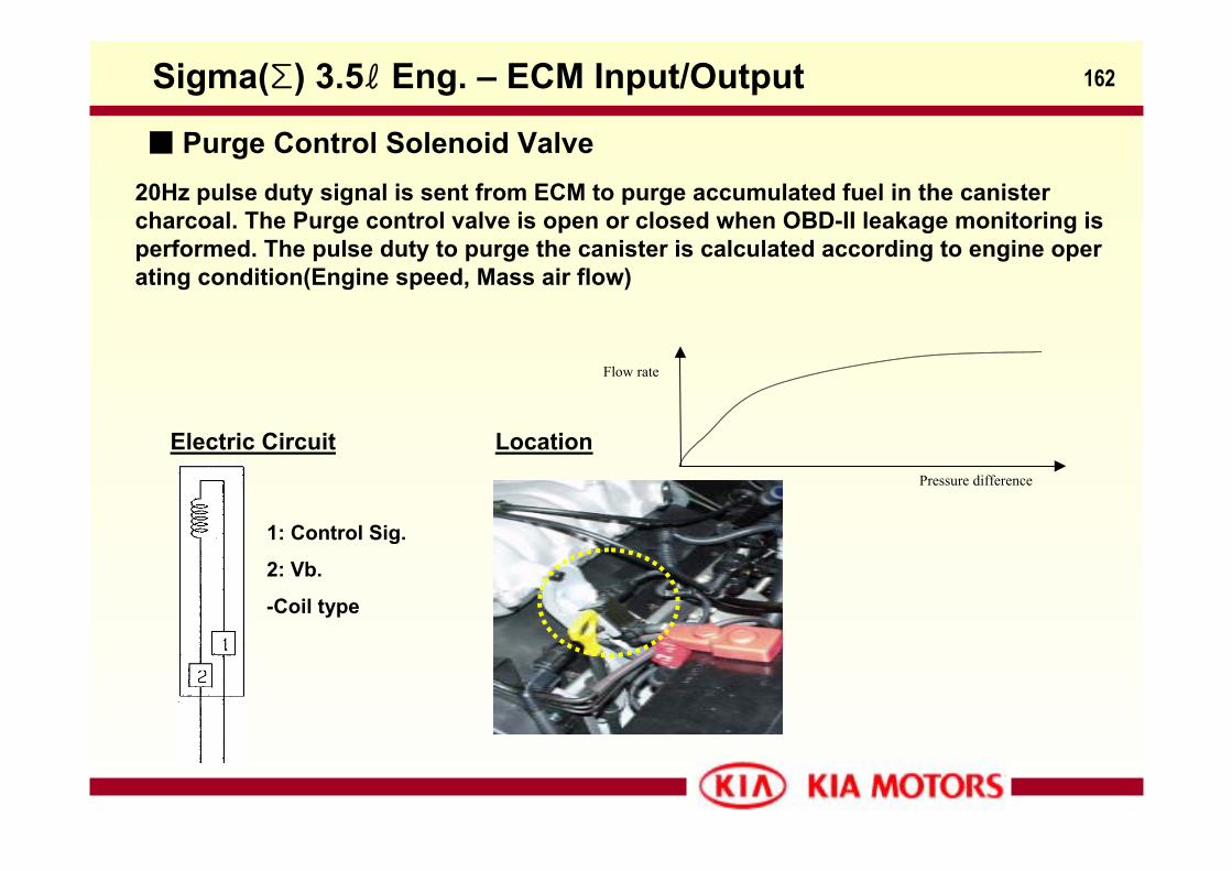
20Hz pulse duty signal is sent from ECM to purge accumulated fuel in the canister charcoal. The Purge control valve is open or closed when OBD-II leakage monitoring is performed. The pulse duty to purge the canister is calculated according to engine operating condition(Engine speed, Mass air flow)
Electric Circuit
Flow rate
Pressure difference
1: Control Sig.
2: Vb.
-Coil type
Location
Sigma(Σ) 3.5ℓ Eng. – ECM Input/Output
Purge Control Solenoid Valve
163
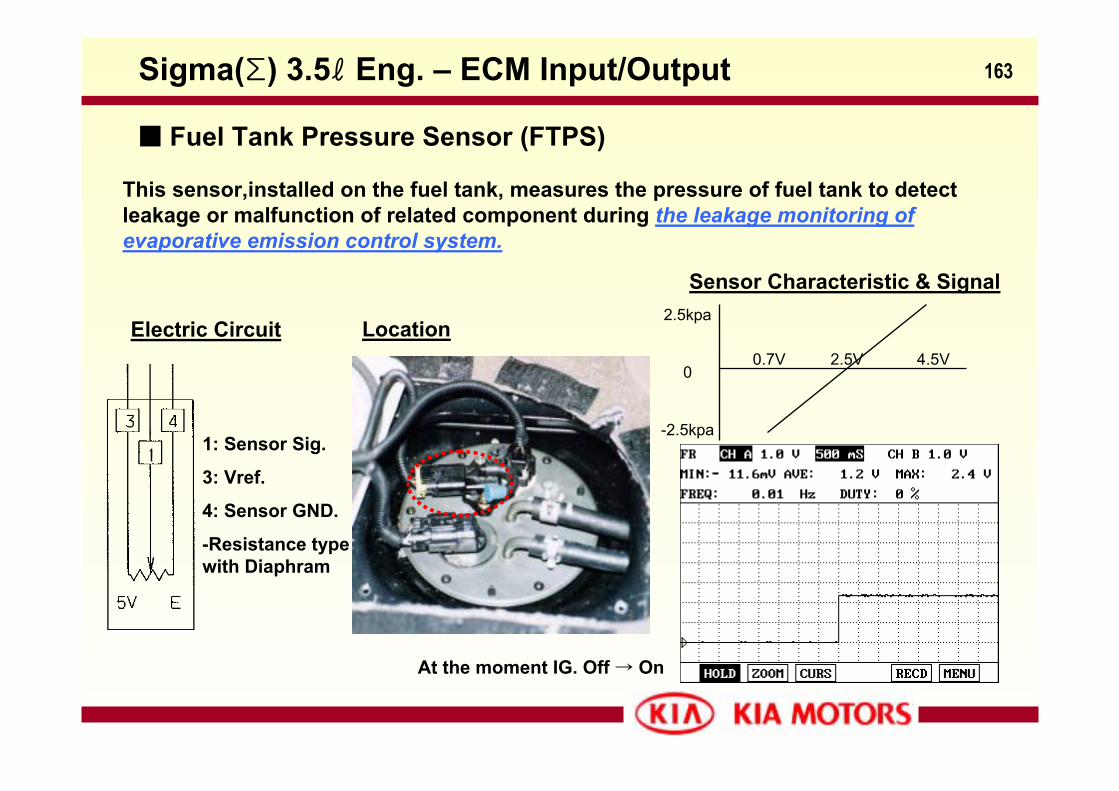
This sensor,installed on the fuel tank, measures the pressure of fuel tank to detect leakage or malfunction of related component during the leakage monitoring of evaporative emission control system.
Electric Circuit
1: Sensor Sig.
3: Vref.
4: Sensor GND.
-Resistance type with Diaphram
Location
Sensor Characteristic & Signal2.5kpa
0
-2.5kpa
0.7V 2.5V 4.5V
At the moment IG. Off → On
Sigma(Σ) 3.5ℓ Eng. – ECM Input/Output
Fuel Tank Pressure Sensor (FTPS)
164
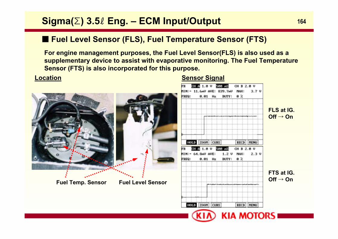
For engine management purposes, the Fuel Level Sensor(FLS) is also used as a supplementary device to assist with evaporative monitoring. The Fuel Temperature Sensor (FTS) is also incorporated for this purpose.
Location
Fuel Temp. Sensor Fuel Level Sensor
Sensor Signal
FLS at IG. Off → On
FTS at IG. Off → On
Sigma(Σ) 3.5ℓ Eng. – ECM Input/Output
Fuel Level Sensor (FLS), Fuel Temperature Sensor (FTS)
165
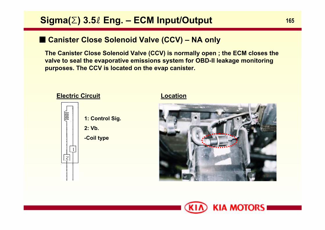
The Canister Close Solenoid Valve (CCV) is normally open ; the ECM closes the valve to seal the evaporative emissions system for OBD-II leakage monitoring purposes. The CCV is located on the evap canister.
Electric Circuit
1: Control Sig.
2: Vb.
-Coil type
Location
Sigma(Σ) 3.5ℓ Eng. – ECM Input/Output
Canister Close Solenoid Valve (CCV) – NA only
166
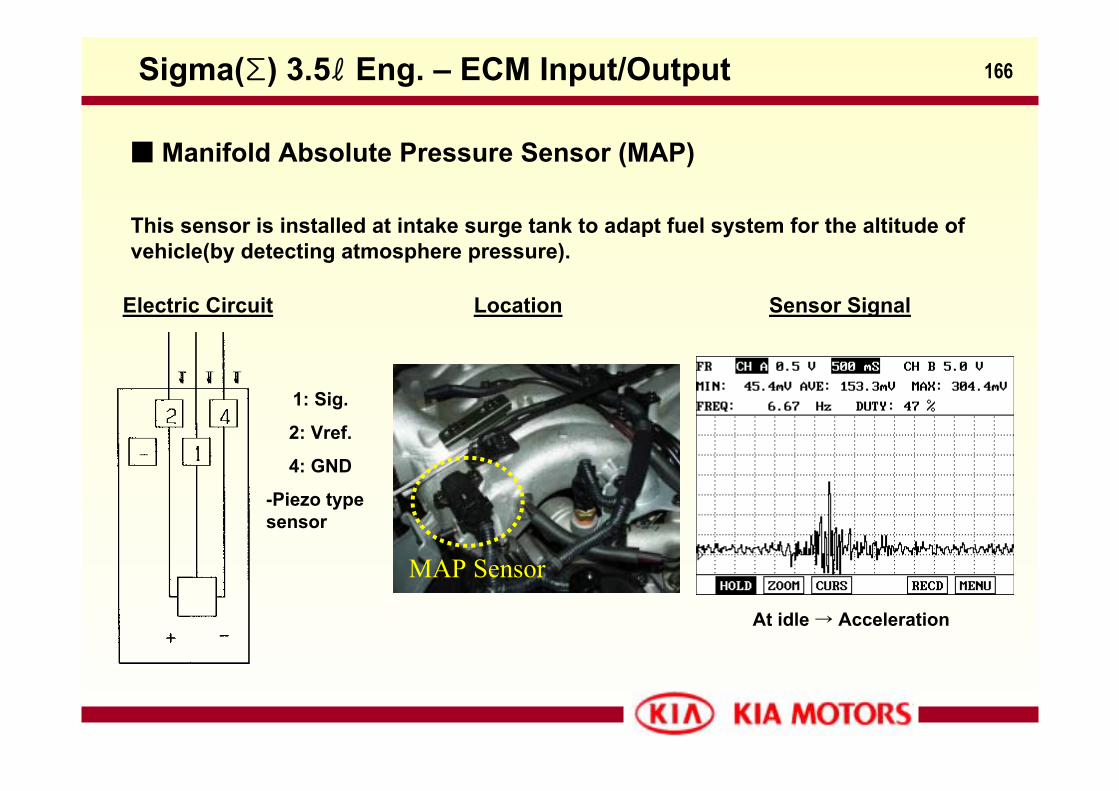
This sensor is installed at intake surge tank to adapt fuel system for the altitude of vehicle(by detecting atmosphere pressure).
Electric Circuit
1: Sig.
2: Vref.
4: GND
-Piezo type sensor
Location Sensor Signal
At idle → Acceleration
Sigma(Σ) 3.5ℓ Eng. – ECM Input/Output
Manifold Absolute Pressure Sensor (MAP)
MAP Sensor
167
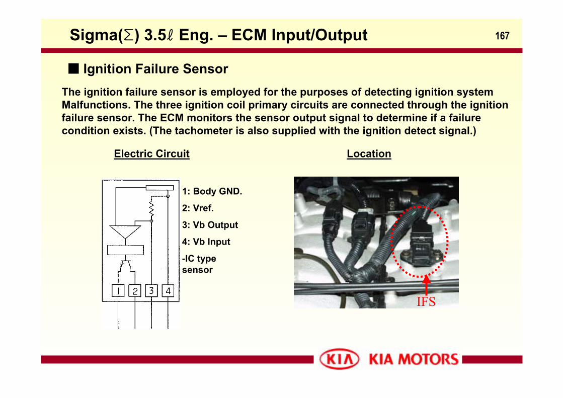
The ignition failure sensor is employed for the purposes of detecting ignition systemMalfunctions. The three ignition coil primary circuits are connected through the ignitionfailure sensor. The ECM monitors the sensor output signal to determine if a failure condition exists. (The tachometer is also supplied with the ignition detect signal.)
1: Body GND.
2: Vref.
3: Vb Output
4: Vb Input
-IC type sensor
Electric Circuit Location
Sigma(Σ) 3.5ℓ Eng. – ECM Input/Output
Ignition Failure Sensor
IFS
168
CKP
CMP
IG. #1
IG. #2
CKP
CMP
IG. #3
IG. Fail. sensor
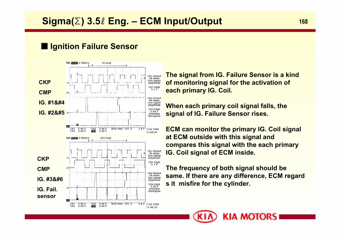
The signal from IG. Failure Sensor is a kind of monitoring signal for the activation of each primary IG. Coil.
When each primary coil signal falls, the signal of IG. Failure Sensor rises.
ECM can monitor the primary IG. Coil signal at ECM outside with this signal and compares this signal with the each primary IG. Coil signal of ECM inside.
The frequency of both signal should be same. If there are any difference, ECM regards it misfire for the cylinder.
Sigma(Σ) 3.5ℓ Eng. – ECM Input/Output
Ignition Failure Sensor
169
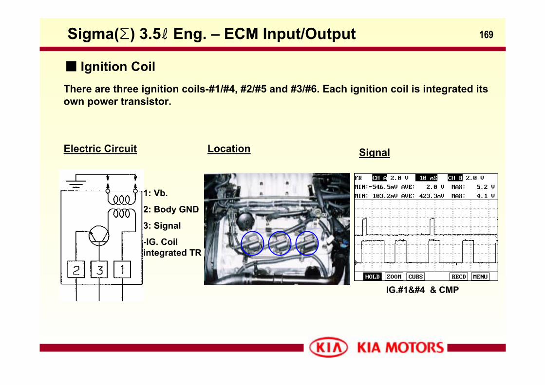
There are three ignition coils-#1/#4, #2/#5 and #3/#6. Each ignition coil is integrated its own power transistor.
1: Vb.
2: Body GND
3: Signal
-IG. Coil integrated TR
Electric Circuit Location Signal
IG.#1 & CMP
Sigma(Σ) 3.5ℓ Eng. – ECM Input/Output
Ignition Coil
170
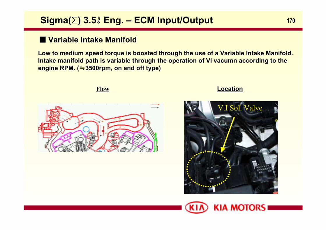
Low to medium speed torque is boosted through the use of a Variable Intake Manifold. Intake manifold path is variable through the operation of VI vacumn according to the engine RPM. (≒3500rpm, on and off type)
Location
Sigma(Σ) 3.5ℓ Eng. – ECM Input/Output
Variable Intake Manifold
V.I Sol. Valve
Flow
171
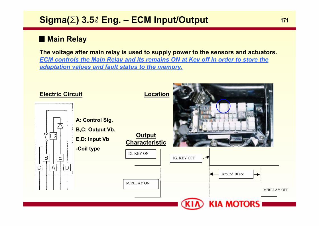
The voltage after main relay is used to supply power to the sensors and actuators.ECM controls the Main Relay and its remains ON at Key off in order to store the adaptation values and fault status to the memory.
Electric Circuit
A: Control Sig.
B,C: Output Vb.
E,D: Input Vb
-Coil type
Location
IG. KEY ON
M/RELAY ON
Around 10 sec
IG. KEY OFF
M/RELAY OFF
Output Characteristic
Sigma(Σ) 3.5ℓ Eng. – ECM Input/Output
Main Relay
172
The signal from the O2 sensor upstream from the monitored catalyst and the associated monitoringoxygen sensor downstream from the catalyst are used to estimate the Oxygen storage capability:
−If a catalyst has good conversion properties, the oxygen fluctuations upstream from the catalyst, generated by the lambda controller, are smoothed by the Oxygen storage capacity of the catalyst.
−If the conversion provided by the catalyst is low due to ageing, poisoning or misfiring, then the fluctuations upstream from the catalyst exist also downstream from the catalyst.
−Calculate a frequency ratio of output signals from the front and rear oxygen sensors according to the following equation.
Rf= Frequency of Rear Oxygen / Frequency of Front Oxygen
if Rf > R0(Threshold value), determine the catalyst malfunction.
Sigma(Σ) 3.5ℓ Eng. – OBD2 Functions
Catalyst Efficiency Monitoring
173
Misfire induces a decrease of the engine speed, therefore a variation in the segment period. The misfiring detection is based on the observation of this variation of segment period.As a result, ECM monitor the fluctuation of crank angular acceleration. If the crank angular acceleration is out of specification, ECM determines misfire on engine.
Main causes of misfiring: -injector shut-off-fuel pressure problems-fuel combustion problems-ignition cut-off…
Misfire fade-out conditions:•Min. engine rpm •Max. engine rpm(6500)•Min. engine load(0)•Max. air mass gradient•Max throttle gradient•Max. ignition angle gradient•Aircon compressor activation•Cylinder shut-off•Rough road detection•Crankshaft oscilation.•Shift change•Sudden deceleration
Carb. A error:•Check recurrence: 200CKP revolution •Target: to avoid cataylist damage
Carb. B error:•Check recurrence: 1000CKP revolution•Emission decrease
Sigma(Σ) 3.5ℓ Eng. – OBD2 Functions
Misfire Monitoring
174
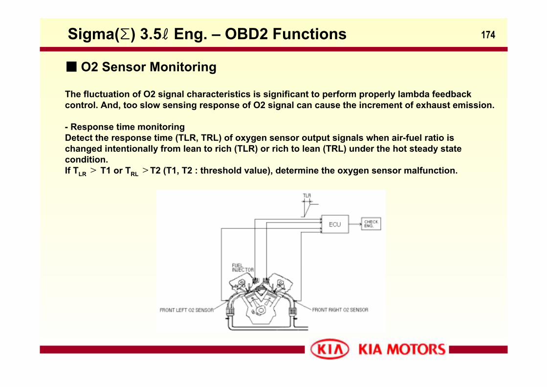
The fluctuation of O2 signal characteristics is significant to perform properly lambda feedback control. And, too slow sensing response of O2 signal can cause the increment of exhaust emission.
- Response time monitoringDetect the response time (TLR, TRL) of oxygen sensor output signals when air-fuel ratio is changed intentionally from lean to rich (TLR) or rich to lean (TRL) under the hot steady state condition.If TLR> T1 or TRL>T2 (T1, T2 : threshold value), determine the oxygen sensor malfunction.
Sigma(Σ) 3.5ℓ Eng. – OBD2 Functions
O2 Sensor Monitoring
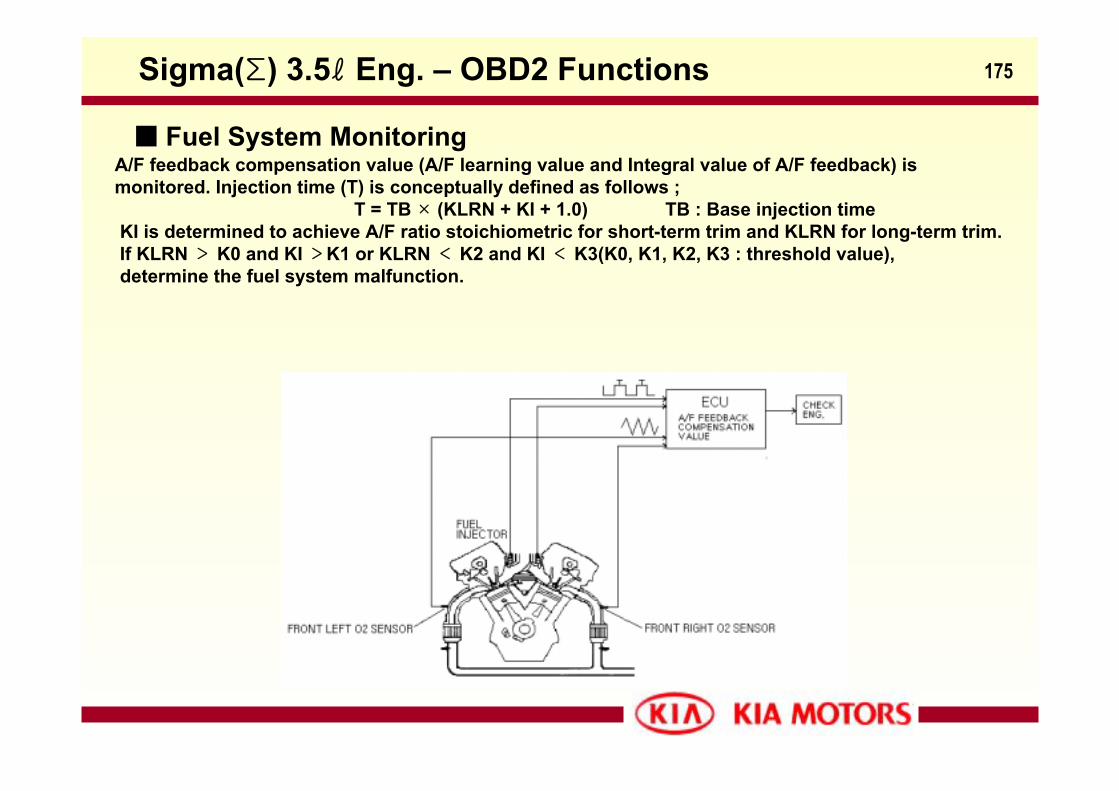
175
A/F feedback compensation value (A/F learning value and Integral value of A/F feedback) is monitored. Injection time (T) is conceptually defined as follows ;
T = TB × (KLRN + KI + 1.0) TB : Base injection timeKI is determined to achieve A/F ratio stoichiometric for short-term trim and KLRN for long-term trim.If KLRN > K0 and KI >K1 or KLRN < K2 and KI < K3(K0, K1, K2, K3 : threshold value),determine the fuel system malfunction.
Sigma(Σ) 3.5ℓ Eng. – OBD2 Functions
Fuel System Monitoring
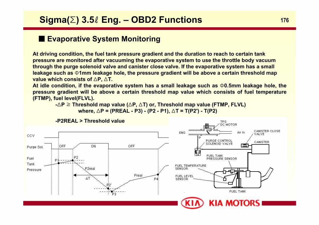
176
At driving condition, the fuel tank pressure gradient and the duration to reach to certain tank pressure are monitored after vacuuming the evaporative system to use the throttle body vacuum through the purge solenoid valve and canister close valve. If the evaporative system has a small leakage such as Φ1mm leakage hole, the pressure gradient will be above a certain threshold map value which consists of ΔP, ΔT. At idle condition, if the evaporative system has a small leakage such as Φ0.5mm leakage hole, the pressure gradient will be above a certain threshold map value which consists of fuel temperature (FTMP), fuel level(FLVL).
-ΔP ≥ Threshold map value (ΔP, ΔT) or, Threshold map value (FTMP, FLVL)where, ΔP = (PREAL - P3) - (P2 - P1), ΔT = T(P2') - T(P2)
-P2REAL > Threshold value
Sigma(Σ) 3.5ℓ Eng. – OBD2 Functions
Evaporative System Monitoring
177
Engine coolant temperature from the sensor voltage is monitored. For thermostat monitoring, three Malfunction criteria (TWTFL_H, TWTFL_M, TWTFL_L) according to intake air flow are reduced per 500msec. Malfunction decision is performed when the counter of malfunction criteria is zero in the case of the engine coolant temperature is over thermostat regulating temperature.
Malfunction ConditionCoolant temperature at start : 5 ∼ 60Coolant temperature at start - Intake air temperature at start < 10Intake air temperature at start - Intake air temperature < 5The integrated time of low air flow(TWOAFS) ≤ 200secThe integrated time of high air flow(TWOAFS_H) ≤ 100sec
Malfunction CriteriaThe counter of malfunction criteria(TWTFL_H, TWTFL_M, TWTFL_L) is changed.intake average air flow(Qave).Qave > 19.2g/sec ⇒ TWTFL_H19.2g/sec > Qave > 11.52 g/sec ⇒ TWTFL_MQave ≤ 11.52g/sec ⇒ TWTFL_L
Sigma(Σ) 3.5ℓ Eng. – OBD2 Functions
Thermostat Monitoring
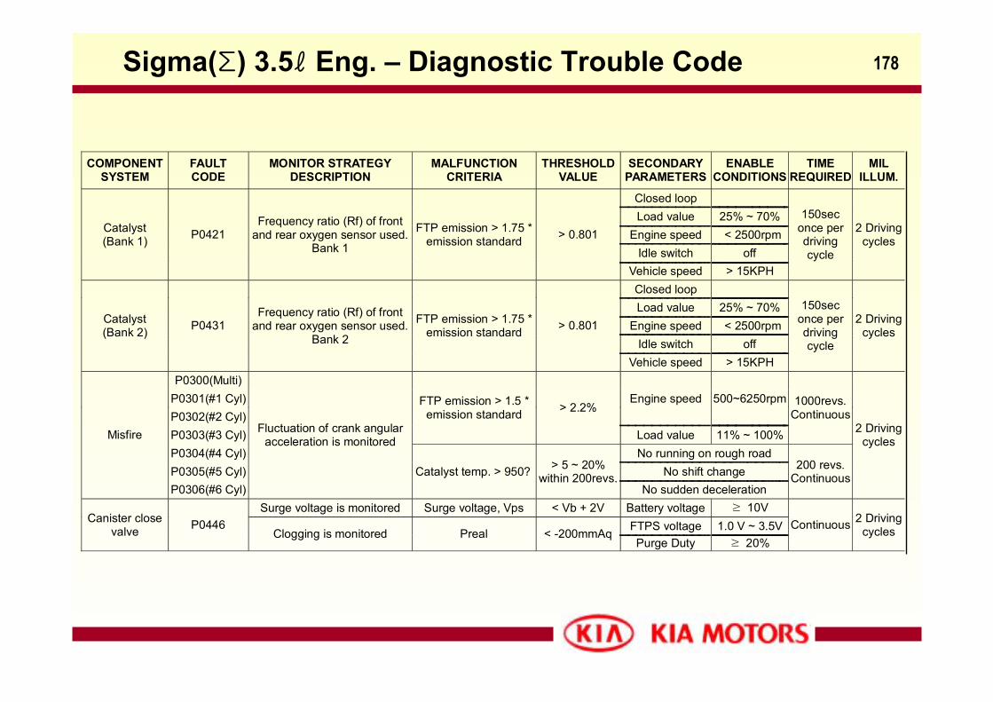
178
COMPONENTSYSTEM
FAULTCODE
MONITOR STRATEGYDESCRIPTION
MALFUNCTIONCRITERIA
THRESHOLDVALUE
SECONDARYPARAMETERS
ENABLECONDITIONS
TIMEREQUIRED
MILILLUM.
Closed loop
Load value 25% ~ 70%Engine speed < 2500rpm
Idle switch off
Catalyst(Bank 1) P0421
Frequency ratio (Rf) of frontand rear oxygen sensor used.
Bank 1
FTP emission > 1.75 *emission standard > 0.801
Vehicle speed > 15KPH
150seconce perdrivingcycle
2 Drivingcycles
Closed loop
Load value 25% ~ 70%Engine speed < 2500rpm
Idle switch off
Catalyst(Bank 2) P0431
Frequency ratio (Rf) of frontand rear oxygen sensor used.
Bank 2
FTP emission > 1.75 *emission standard > 0.801
Vehicle speed > 15KPH
150seconce perdrivingcycle
2 Drivingcycles
P0300(Multi)P0301(#1 Cyl)P0302(#2 Cyl)
Engine speed 500~6250rpm
P0303(#3 Cyl)
FTP emission > 1.5 *emission standard > 2.2%
Load value 11% ~ 100%
1000revs.Continuous
P0304(#4 Cyl) No running on rough roadP0305(#5 Cyl) No shift change
Misfire
P0306(#6 Cyl)
Fluctuation of crank angularacceleration is monitored
Catalyst temp. > 950? > 5 ~ 20%within 200revs.
No sudden deceleration
200 revs.Continuous
2 Drivingcycles
Surge voltage is monitored Surge voltage, Vps < Vb + 2V Battery voltage ≥ 10VFTPS voltage 1.0 V ~ 3.5VCanister close
valve P0446Clogging is monitored Preal < -200mmAq
Purge Duty ≥ 20%Continuous 2 Driving
cycles
Sigma(Σ) 3.5ℓ Eng. – Diagnostic Trouble Code
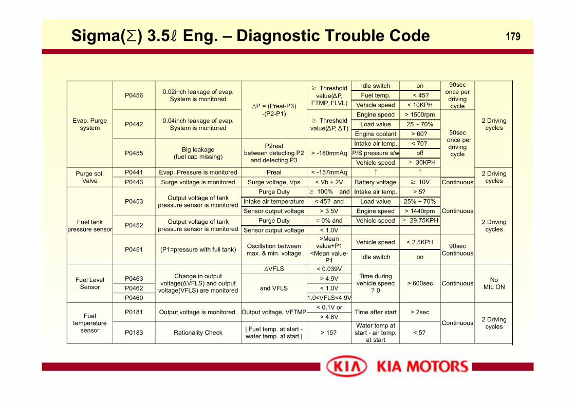
179
Idle switch onFuel temp. < 45?P0456 0.02inch leakage of evap.
System is monitored
≥ Thresholdvalue(∆P,
FTMP, FLVL) Vehicle speed < 10KPH
90seconce perdrivingcycle
Engine speed > 1500rpmLoad value 25 ~ 70%P0442 0.04inch leakage of evap.
System is monitored
ΔP = (Preal-P3)-(P2-P1)
≥ Thresholdvalue(∆P, ∆T)
Engine coolant > 60?Intake air temp. < 70?
P/S pressure s/w off
Evap. Purgesystem
P0455 Big leakage(fuel cap missing)
P2realbetween detecting P2
and detecting P3> -180mmAq
Vehicle speed ≥ 30KPH
2 Drivingcycles
P0441 Evap. Pressure is monitored Preal < -157mmAq ↑ ↑
50sec once per
drivingcycle
Purge sol.Valve P0443 Surge voltage is monitored Surge voltage, Vps < Vb + 2V Battery voltage ≥ 10V Continuous
2 Drivingcycles
Purge Duty ≥ 100% and Intake air temp. > 5?Intake air temperature < 45? and Load value 25% ~ 70%P0453 Output voltage of tank
pressure sensor is monitoredSensor output voltage > 3.5V Engine speed > 1440rpm
Purge Duty = 0% and Vehicle speed ≥ 29.75KPHP0452 Output voltage of tank
pressure sensor is monitored Sensor output voltage < 1.0V
Continuous
>Meanvalue+P1 Vehicle speed < 2.5KPH
Fuel tankpressure sensor
P0451 (P1=pressure with full tank) Oscillation betweenmax. & min. voltage <Mean value-
P1 Idle switch on
90secContinuous
2 Drivingcycles
ΔVFLS < 0.039VP0463 > 4.9VP0462 < 1.0V
Fuel LevelSensor
P0460
Change in outputvoltage(∆VFLS) and output
voltage(VFLS) are monitored and VFLS1.0<VFLS<4.9V
Time duringvehicle speed
? 0> 600sec Continuous No
MIL ON
< 0.1V orP0181 Output voltage is monitored. Output voltage, VFTMP
> 4.6VTime after start > 2secFuel
temperaturesensor P0183 Rationality Check | Fuel temp. at start -
water temp. at start | > 15?Water temp atstart - air temp.
at start< 5?
Continuous 2 Drivingcycles
Sigma(Σ) 3.5ℓ Eng. – Diagnostic Trouble Code
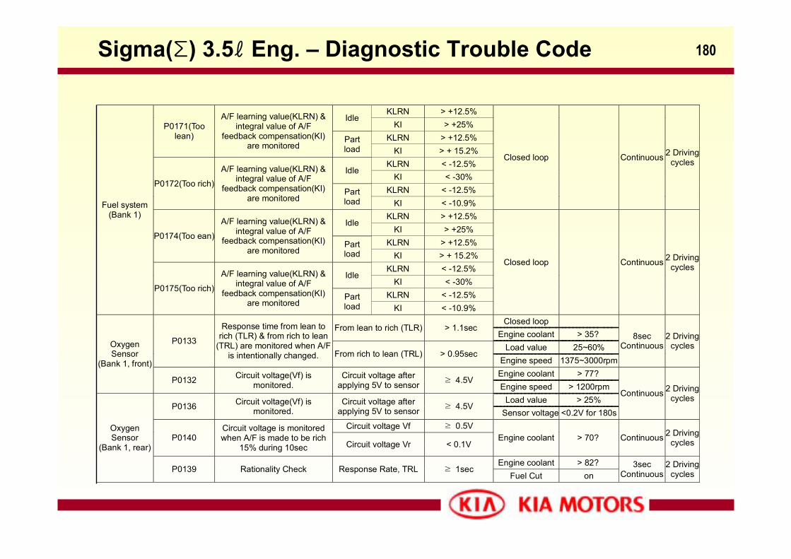
180
KLRN > +12.5% Idle
KI > +25%
KLRN > +12.5%
P0171(Toolean)
A/F learning value(KLRN) &integral value of A/F
feedback compensation(KI)are monitored
Partload KI > + 15.2%
KLRN < -12.5% Idle
KI < -30%
KLRN < -12.5% P0172(Too rich)
A/F learning value(KLRN) &integral value of A/F
feedback compensation(KI)are monitored
Partload KI < -10.9%
Closed loop
Continuous 2 Drivingcycles
KLRN > +12.5% Idle
KI > +25%
KLRN > +12.5% P0174(Too ean)
A/F learning value(KLRN) &integral value of A/F
feedback compensation(KI)are monitored
Partload KI > + 15.2%
KLRN < -12.5% Idle
KI < -30%
KLRN < -12.5%
Fuel system(Bank 1)
P0175(Too rich)
A/F learning value(KLRN) &integral value of A/F
feedback compensation(KI)are monitored
Partload KI < -10.9%
Closed loop
Continuous 2 Drivingcycles
Closed loop From lean to rich (TLR) > 1.1sec
Engine coolant > 35?Load value 25~60%
P0133
Response time from lean torich (TLR) & from rich to lean
(TRL) are monitored when A/Fis intentionally changed. From rich to lean (TRL) > 0.95sec
Engine speed 1375~3000rpm
8secContinuous
2 Drivingcycles
Engine coolant > 77?
OxygenSensor
(Bank 1, front)
P0132 Circuit voltage(Vf) ismonitored.
Circuit voltage afterapplying 5V to sensor ≥ 4.5V
Engine speed > 1200rpmLoad value > 25%
P0136 Circuit voltage(Vf) ismonitored.
Circuit voltage afterapplying 5V to sensor ≥ 4.5V
Sensor voltage <0.2V for 180s
Continuous 2 Drivingcycles
Circuit voltage Vf ≥ 0.5VP0140
Circuit voltage is monitoredwhen A/F is made to be rich
15% during 10sec Circuit voltage Vr < 0.1VEngine coolant > 70? Continuous 2 Driving
cycles
Engine coolant > 82?
OxygenSensor
(Bank 1, rear)
P0139 Rationality Check Response Rate, TRL ≥ 1secFuel Cut on
3secContinuous
2 Drivingcycles
Sigma(Σ) 3.5ℓ Eng. – Diagnostic Trouble Code
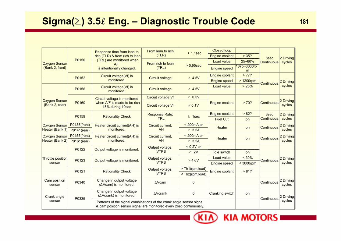
181
Closed loop From lean to rich (TLR) > 1.1sec
Engine coolant > 35?Load value 25~60%P0150
Response time from lean to rich (TLR) & from rich to lean
(TRL) are monitored whenA/F
is intentionally changed.From rich to lean
(TRL) > 0.95secEngine speed 1375~3000rp
m
8secContinuous
2 Drivingcycles
Engine coolant > 77?
Oxygen Sensor(Bank 2, front)
P0152 Circuit voltage(Vf) ismonitored. Circuit voltage ≥ 4.5V
Engine speed > 1200rpmLoad value > 25%
P0156 Circuit voltage(Vf) ismonitored. Circuit voltage ≥ 4.5V
Continuous 2 Drivingcycles
Circuit voltage Vf ≥ 0.5VP0160
Circuit voltage is monitored when A/F is made to be rich
15% during 10sec Circuit voltage Vr < 0.1VEngine coolant > 70? Continuous 2 Driving
cycles
Engine coolant > 82?
Oxygen Sensor(Bank 2, rear)
P0159 Rationality Check Response Rate, TRL ≥ 1sec
Fuel Cut on3sec
Continuous2 Driving
cycles
P0135(front) < 200mA orOxygen SensorHeater (Bank 1) P0141(rear)
Heater circuit current(AH) ismonitored.
Circuit current, AH ≥ 3.5A
Heater on Continuous 2 Drivingcycles
P0155(front) < 200mA orOxygen SensorHeater (Bank 2) P0161(rear)
Heater circuit current(AH) ismonitored.
Circuit current, AH ≥ 3.5A
Heater on Continuous 2 Drivingcycles
< 0.2V or P0122 Output voltage is monitored. Output voltage,
VTPS ≥ 2V Idle switch onLoad value < 30%
P0123 Output voltage is monitored. Output voltage, VTPS > 4.6V
Engine speed < 3000rpm> Th1(rpm,load)
Throttle positionsensor
P0121 Rationality Check Output voltage, VTPS < Th2(rpm,load)
Engine coolant > 81?
Continuous 2 Drivingcycles
Cam positionsensor P0340 Change in output voltage
(∆Vcam) is monitored. ΔVcam 0 Continuous 2 Drivingcycles
Change in output voltage(∆Vcrank) is monitored. ΔVcrank 0 Cranking switch on
Crank anglesensor P0335
Patterns of the signal combinations of the crank angle sensor signal& cam position sensor signal are monitored every 2sec continuously.
Continuous 2 Drivingcycles
Sigma(Σ) 3.5ℓ Eng. – Diagnostic Trouble Code
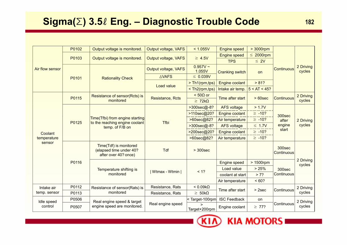
182
P0102 Output voltage is monitored. Output voltage, VAFS < 1.055V Engine speed > 3000rpmEngine speed ≤ 2000rpm
P0103 Output voltage is monitored. Output voltage, VAFS ≥ 4.5VTPS ≤ 2V
Output voltage, VAFS 0.957V ~1.055V
ΔVAFS ≤ 0.039VCranking switch on
> Th1(rpm,tps) Engine coolant > 81?
Air flow sensor
P0101 Rationality Check
Load value< Th2(rpm,tps) Intake air temp. 5 < AT < 45?
Continuous 2 Drivingcycles
< 50Ω orP0115 Resistance of sensor(Rcts) is
monitored Resistance, Rcts≥ 72kΩ
Time after start > 60sec Continuous 2 Drivingcycles
>300sec@-8? AFS voltage > 1.7V>110sec@20? Engine coolant ≥ -10?>60sec@82? Air temperature ≥ -10?>300sec@-8? AFS voltage ≤ 1.7V>200sec@20? Engine coolant ≥ -10?
P0125Time(Tfbi) from engine startingto the reaching engine coolant
temp. of F/B onTfbi
>60sec@82? Air temperature ≥ -10?
300secafter
enginestart
2 Drivingcycles
Time(Tdf) is monitored
(elapsed time under 40?after over 40? once)
Tdf > 300sec
300secContinuous
Engine speed > 1500rpmLoad value > 25%
coolant at start > 7?
Coolanttemperature
sensor
P0116
Temperature shifting ismonitored | Wtmax - Wtmin | < 1?
Air temperature < 60?
300secContinuous
2 Drivingcycles
P0112 Resistance, Rats < 0.09kΩIntake airtemp. sensor P0113
Resistance of sensor(Rats) ismonitored Resistance, Rats ≥ 50kΩ
Time after start > 2sec Continuous 2 Drivingcycles
P0506 < Target-100rpm ISC Feedback onIdle speedcontrol P0507
Real engine speed & targetengine speed are monitored. Real engine speed >
Target+200rpm Engine coolant ≥ 77?Continuous 2 Driving
cycles
Sigma(Σ) 3.5ℓ Eng. – Diagnostic Trouble Code
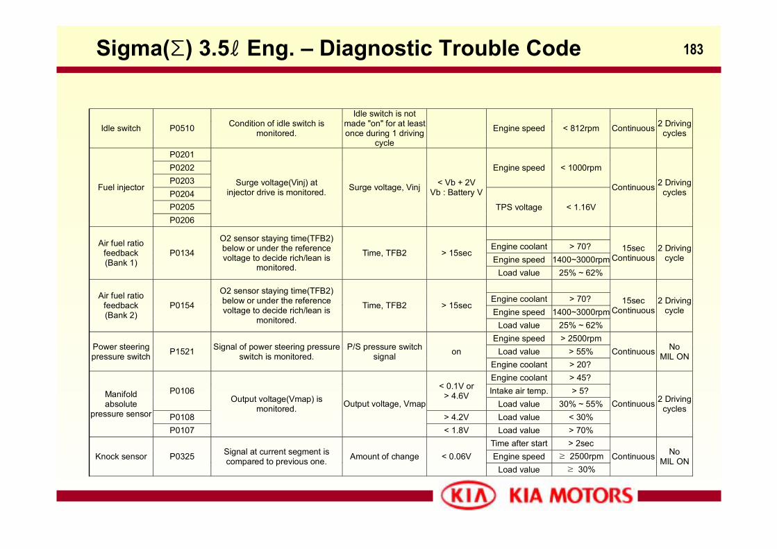
183
Idle switch P0510 Condition of idle switch ismonitored.
Idle switch is notmade "on" for at leastonce during 1 driving
cycle Engine speed < 812rpm Continuous 2 Driving
cycles
P0201P0202P0203
Engine speed < 1000rpm
P0204P0205
Fuel injector
P0206
Surge voltage(Vinj) atinjector drive is monitored. Surge voltage, Vinj < Vb + 2V
Vb : Battery V
TPS voltage < 1.16V
Continuous 2 Drivingcycles
Engine coolant > 70?Engine speed 1400~3000rpm
Air fuel ratiofeedback(Bank 1)
P0134
O2 sensor staying time(TFB2)below or under the referencevoltage to decide rich/lean is
monitored.
Time, TFB2 > 15sec
Load value 25% ~ 62%
15secContinuous
2 Drivingcycle
Engine coolant > 70?Engine speed 1400~3000rpm
Air fuel ratiofeedback(Bank 2)
P0154
O2 sensor staying time(TFB2)below or under the referencevoltage to decide rich/lean is
monitored.
Time, TFB2 > 15sec
Load value 25% ~ 62%
15secContinuous
2 Drivingcycle
Engine speed > 2500rpmLoad value > 55%Power steering
pressure switch P1521 Signal of power steering pressureswitch is monitored.
P/S pressure switchsignal on
Engine coolant > 20?Continuous No
MIL ON
Engine coolant > 45?Intake air temp. > 5?P0106 < 0.1V or
> 4.6VLoad value 30% ~ 55%
P0108 > 4.2V Load value < 30%
Manifoldabsolute
pressure sensor
P0107
Output voltage(Vmap) ismonitored. Output voltage, Vmap
< 1.8V Load value > 70%
Continuous 2 Drivingcycles
Time after start > 2secEngine speed ≥ 2500rpmKnock sensor P0325 Signal at current segment is
compared to previous one. Amount of change < 0.06VLoad value ≥ 30%
Continuous NoMIL ON
Sigma(Σ) 3.5ℓ Eng. – Diagnostic Trouble Code
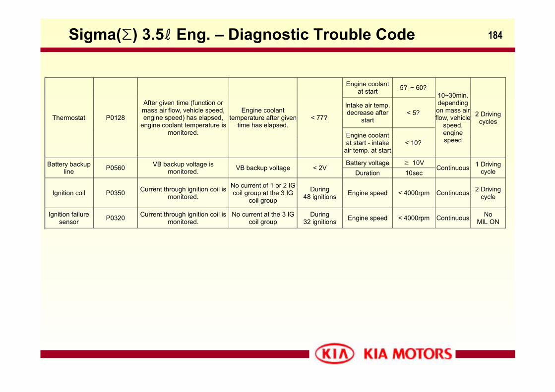
184
Engine coolantat start 5? ~ 60?
Intake air temp.decrease after
start< 5?
Thermostat P0128
After given time (function ormass air flow, vehicle speed,engine speed) has elapsed,
engine coolant temperature ismonitored.
Engine coolanttemperature after given
time has elapsed.< 77?
Engine coolantat start - intake
air temp. at start< 10?
10~30min.dependingon mass airflow, vehicle
speed,enginespeed
2 Drivingcycles
Battery voltage ≥ 10VBattery backupline P0560 VB backup voltage is
monitored. VB backup voltage < 2VDuration 10sec
Continuous 1 Drivingcycle
Ignition coil P0350 Current through ignition coil ismonitored.
No current of 1 or 2 IGcoil group at the 3 IG
coil group
During48 ignitions Engine speed < 4000rpm Continuous 2 Driving
cycle
Ignition failuresensor P0320 Current through ignition coil is
monitored.No current at the 3 IG
coil groupDuring
32 ignitions Engine speed < 4000rpm Continuous NoMIL ON
Sigma(Σ) 3.5ℓ Eng. – Diagnostic Trouble Code
185
Sirius2-Engine
Sirius Ⅱ 2.4ℓ Eng.
186
Contents- General Description
- Engine Feature
- Timing Belt
- Engine Tightening Torque
- ECM Overview
- ECM Input/Output
Sirius Ⅱ 2.4ℓ Eng. - Contents
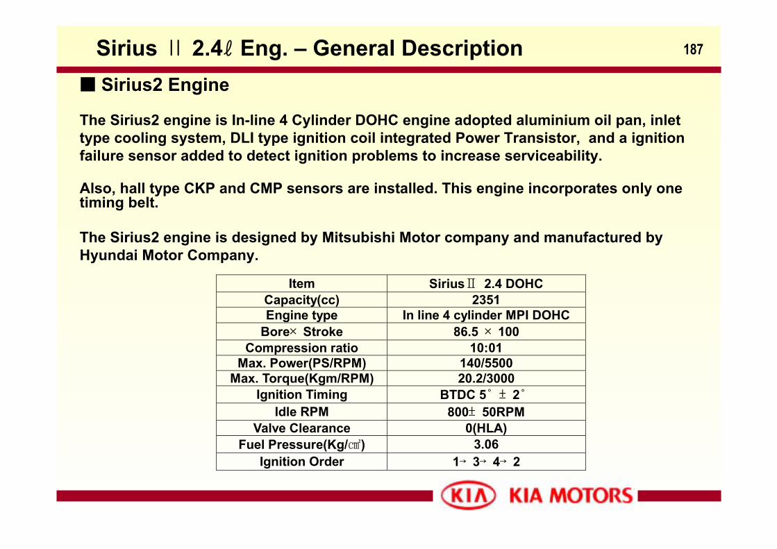
187
Sirius2 Engine
The Sirius2 engine is In-line 4 Cylinder DOHC engine adopted aluminium oil pan, inlet type cooling system, DLI type ignition coil integrated Power Transistor, and a ignition failure sensor added to detect ignition problems to increase serviceability.
Also, hall type CKP and CMP sensors are installed. This engine incorporates only one timing belt.
The Sirius2 engine is designed by Mitsubishi Motor company and manufactured by Hyundai Motor Company.
Item SiriusⅡ 2.4 DOHC Capacity(cc) 2351 Engine type In line 4 cylinder MPI DOHC
Bore× Stroke 86.5 × 100 Compression ratio 10:01
Max. Power(PS/RPM) 140/5500 Max. Torque(Kgm/RPM) 20.2/3000
Ignition Timing BTDC 5˚ ± 2˚ Idle RPM 800± 50RPM
Valve Clearance 0(HLA) Fuel Pressure(Kg/) 3.06
Ignition Order 1→ 3→ 4→ 2
Sirius Ⅱ 2.4ℓ Eng. – General Description
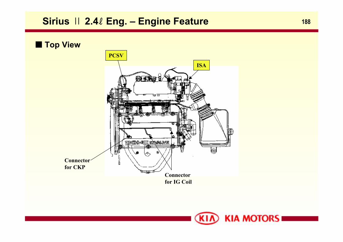
188
Top ViewPCSV
Connectorfor CKP
ISA
Connector for IG Coil
Sirius Ⅱ 2.4ℓ Eng. – Engine Feature
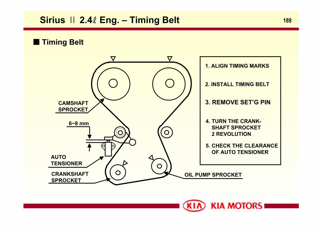
189
6~8 mm
AUTO TENSIONER
2. INSTALL TIMING BELT
1. ALIGN TIMING MARKS
3. REMOVE SET’G PIN
4. TURN THE CRANK-SHAFT SPROCKET2 REVOLUTION
5. CHECK THE CLEARANCEOF AUTO TENSIONER
CAMSHAFT SPROCKET
CRANKSHAFTSPROCKET
OIL PUMP SPROCKET
Timing Belt
Sirius Ⅱ 2.4ℓ Eng. – Timing Belt
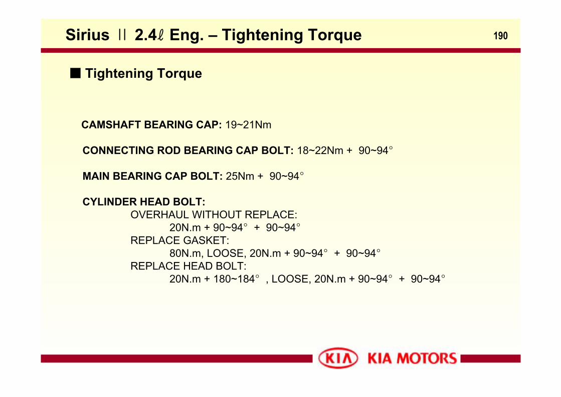
190
Tightening Torque
CAMSHAFT BEARING CAP: 19~21Nm
CONNECTING ROD BEARING CAP BOLT: 18~22Nm + 90~94°
MAIN BEARING CAP BOLT: 25Nm + 90~94°
CYLINDER HEAD BOLT:OVERHAUL WITHOUT REPLACE:
20N.m + 90~94° + 90~94°REPLACE GASKET:
80N.m, LOOSE, 20N.m + 90~94° + 90~94°REPLACE HEAD BOLT:
20N.m + 180~184° , LOOSE, 20N.m + 90~94° + 90~94°
Sirius Ⅱ 2.4ℓ Eng. – Tightening Torque
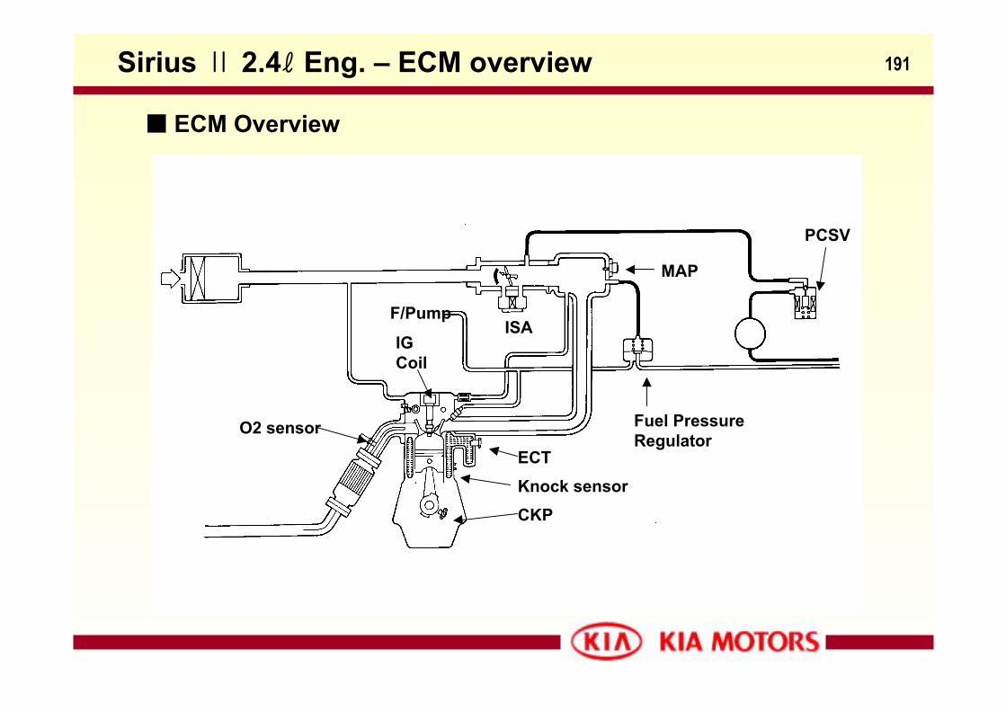
191
CKPKnock sensorECT
O2 sensor
ISA
MAP
Fuel PressureRegulator
PCSV
IG Coil
F/Pump
Sirius Ⅱ 2.4ℓ Eng. – ECM overview
ECM Overview
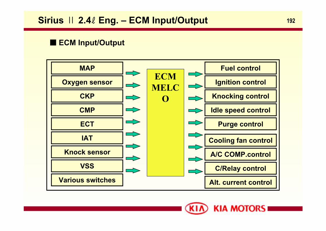
192
MAP
Oxygen sensor
CKP
CMP
ECT
IAT
Knock sensor
VSS
Various switches
Fuel control
Ignition control
Knocking control
Idle speed control
Purge control
Cooling fan control
A/C COMP.control
C/Relay control
Alt. current control
ECMMELC
O
ECM Input/Output
Sirius Ⅱ 2.4ℓ Eng. – ECM Input/Output