BIOS Setup (Intel 600 Series)
28
- 1 - The BIOS Setup menus and options described in this chapter may differ from the exact settings for your motherboard. The actual BIOS Setup menu options are dependent on the motherboard you have and the BIOS version. BIOS Setup (Intel ® 600 Series) BIOS Setup ................................................................................................................... 2 Startup Screen .............................................................................................................. 3 The Main Menu ............................................................................................................. 4 Smart Fan 6 .................................................................................................................. 6 Favorites (F11) .............................................................................................................. 8 Tweaker ........................................................................................................................ 9 Settings ...................................................................................................................... 17 System Information ..................................................................................................... 24 Boot............................................................................................................................. 25 Save & Exit ................................................................................................................. 28
Transcript of BIOS Setup (Intel 600 Series)

- 1 -
The BIOS Setup menus and options described in this chapter may differ from the exact settings for your motherboard. The actual BIOS Setup menu options are dependent on the motherboard you have and the BIOS version.
BIOS Setup (Intel® 600 Series)
BIOS Setup ................................................................................................................... 2Startup Screen .............................................................................................................. 3The Main Menu ............................................................................................................. 4Smart Fan 6 .................................................................................................................. 6Favorites (F11) .............................................................................................................. 8Tweaker ........................................................................................................................ 9Settings ...................................................................................................................... 17System Information ..................................................................................................... 24Boot ............................................................................................................................. 25Save & Exit ................................................................................................................. 28

- 2 -
BIOS (Basic Input and Output System) records hardware parameters of the system in the CMOS on the motherboard. Its major functions include conducting the Power-On Self-Test (POST) during system startup, saving system parameters and loading operating system, etc. BIOS includes a BIOS Setup program that allows the user to modify basic system configuration settings or to activate certain system features.
When the power is turned off, the battery on the motherboard supplies the necessary power to the CMOS to keep the configuration values in the CMOS.
To access the BIOS Setup program, press the <Delete> key during the POST when the power is turned on.
To upgrade the BIOS, use either the GIGABYTE Q-Flash or @BIOS utility. • Q-Flash allows the user to quickly and easily upgrade or back up BIOS without entering the operating system. • @BIOS is a Windows-based utility that searches and downloads the latest version of BIOS from the Internet
and updates the BIOS.For instructions on using the Q-Flash and @BIOS utilities, please navigate to the "Unique Features" page of GIGABYTE's website and search for "BIOS Update Utilities."
• Because BIOS flashing is potentially risky, if you do not encounter problems using the current version of BIOS, it is recommended that you not flash the BIOS. To flash the BIOS, do it with caution. Inadequate BIOS flashing may result in system malfunction.
• It is recommended that you not alter the default settings (unless you need to) to prevent system instability or other unexpected results. Inadequately altering the settings may result in system's failure to boot. If this occurs, try to clear the CMOS values and reset the board to default values.
• Refer to the introductions of the battery/clear CMOS jumper/button in user's manual or refer to the "Load Optimized Defaults" section for how to clear the CMOS values.
BIOS Setup

- 3 -
Startup ScreenThe following startup Logo screen will appear when the computer boots. (The screen may vary from motherboards.)
Function Keys:<DEL>: BIOS SETUP\Q-FLASH Press the <Delete> key to enter BIOS Setup or to access the Q-Flash utility in BIOS Setup.<F12>: BOOT MENU Boot Menu allows you to set the first boot device without entering BIOS Setup. In Boot Menu, use the up
arrow key <h> or the down arrow key <i> to select the first boot device, then press <Enter> to accept. The system will boot from the device immediately.
Note: The setting in Boot Menu is effective for one time only. After system restart, the device boot order will still be based on BIOS Setup settings.
<END>: Q-FLASH Press the <End> key to access the Q-Flash utility directly without having to enter BIOS Setup first.
Function Keys

- 4 -
The Main MenuAdvanced ModeThe Advanced Mode provides detailed BIOS settings. You can press the arrow keys on your keyboard to move among the items and press <Enter> to accept or enter a sub-menu. Or you can use your mouse to select the item you want.
Hardware Infor-mation
Option Description Current Settings
Setup Menus
Configuration Items
System Time
Quick Access Bar allows you to quickly move to the General Help, Easy Mode, Smart Fan 6, or Q-Flash screen.
Advanced Mode Function Keys<f><g> Move the selection bar to select a setup menu<h><i> Move the selection bar to select an configuration item on a menu<Enter>/Double Click Execute command or enter a menu<+>/<Page Up> Increase the numeric value or make changes<->/<Page Down> Decrease the numeric value or make changes<F1> Show descriptions of the function keys<F2> Switch to Easy Mode<F3> Save the current BIOS settings to a profile<F4> Load the BIOS settings from a profile created before<F5> Restore the previous BIOS settings for the current submenus<F6> Display the Smart Fan 6 screen<F7> Load the Optimized BIOS default settings for the current submenus<F8> Access the Q-Flash utility<F10> Save all the changes and exit the BIOS Setup program<F11> Switch to the Favorites submenu<F12> Capture the current screen as an image and save it to your USB drive<Insert> Add or remove a favorite option<Ctrl>+<S> Display information on the installed memory
<Esc>Main Menu: Exit the BIOS Setup program Submenus: Exit current submenu

- 5 -
B. Easy ModeEasy Mode allows users to quickly view their current system information or to make adjustments for optimum performance. In Easy Mode, you can use your mouse to move through configuration items or press <F2> to switch to the Advanced Mode screen.

- 6 -
Use the <F6> function key to quickly switch to this screen. This screen allows you to configure fan speed related settings for each fan header or monitor your system/CPU temperature.
& TUNE ALL Allows you to apply the current settings to all fan headers.
& Temperature Displays the current temperature of the selected target area.
& Fan Speed Displays current fan/pump speeds.
& Flow Rate Displays the flow rate of your water cooling system. Press <Enter> on Fan Speed to switch to this function.
& Fan Speed Control Allows you to determine whether to enable the fan speed control function and adjust the fan speed.
�Normal Allows the fan to run at different speeds according to the temperature. You can adjust the fan speed with System Information Viewer based on your system requirements.
�Silent Allows the fan to run at slow speeds. �Manual Allows you to drag the curve nodes to adjust fan speed. Or you can use the EZ Tuning
feature. After adjusting the node position, press Apply to automatically calculate the slope of the curve.
�Full Speed Allows the fan to run at full speeds. & Fan Control Use Temperature Input
Allows you to select the reference temperature for fan speed control. & Temperature Interval
Allows you to select the temperature interval for fan speed change. & FAN/PUMP Control Mode
�Auto Lets the BIOS automatically detect the type of fan installed and sets the optimal control mode.
�Voltage Voltage mode is recommended for a 3-pin fan/pump. �PWM PWM mode is recommended for a 4-pin fan/pump.
Smart Fan 6

- 7 -
& FAN/PUMP Stop Enables or disables the fan/pump stop function. You can set the temperature limit using the temperature
curve. The fan or pump stops operation when the temperature is lower than the limit. & FAN/PUMP Mode
Allows you to set the operating mode for the fan. �Slope Adjusts the fan speed linearly based on the temperature. �Stair Adjusts the fan speed stepwise based on the temperature.
& FAN/PUMP Fail Warning Allows the system to emit warning sound if the fan/pump is not connected or fails. Check the fan/pump
condition or fan/pump connection when this occurs. & Save Fan Profile
This function allows you to save the current settings to a profile. You can save the profile in the BIOS or select Select File in HDD/FDD/USB to save the profile to your storage device.
& Load Fan Profile This function allows you to load a previously saved BIOS profile without the hassles of reconfiguring the
BIOS settings. Or you can select Select File in HDD/FDD/USB to load a profile from your storage device.

- 8 -
Favorites (F11)
Set your frequently used options as your favorites and use the <F11> key to quickly switch to the page where all of your favorite options are located. To add or remove a favorite option, go to its original page and press <Insert> on the option. The option is marked with a star sign if set as a "favorite."

- 9 -
Tweaker
& CPU Upgrade (Note)
Allows you to set the CPU frequency. The final result may vary depending on the CPU used. Options are: Default, Gaming Profile, Advanced Profile.
& CPU Base Clock (Note)
Allows you to manually set the CPU base clock in 0.01 MHz increments. Important: It is highly recommended that the CPU frequency be set in accordance with the CPU specifications.
& Enhanced Multi-Core Performance (Note)
Determines whether to allow the CPU to run at Turbo 1C speed. & CPU Clock Ratio
Allows you to alter the clock ratio for the installed CPU. The adjustable range is dependent on the CPU being installed.
& Performance CPU Clock Ratio Allows you to alter the clock ratio for the installed Performance CPU. The adjustable range is dependent
on the CPU being installed. & Efficiency CPU Clock Ratio
Allows you to alter the clock ratio for the installed Efficiency CPU. The adjustable range is dependent on the CPU being installed.
& Ring Ratio Allows you to set the CPU Uncore ratio. The adjustable range is dependent on the CPU being used.
Whether the system will work stably with the overclock/overvoltage settings you made is dependent on your overall system configurations. Incorrectly doing overclock/overvoltage may result in damage to CPU, chipset, or memory and reduce the useful life of these components. This page is for advanced users only and we recommend you not to alter the default settings to prevent system instability or other unexpected results. (Inadequately altering the settings may result in system's failure to boot. If this occurs, clear the CMOS values and reset the board to default values.)
(Note) This item is available only when the motherboard chipset and the CPU used support this feature. For more information about Intel® CPUs' unique features, please visit Intel's website.

- 10 -
& PVD Ratio Threshold Override (Note)
Allows you to determine whether to improve performance under extreme BCLK OC by reducing a “PLL Banding” condition caused in part by a very high DCO frequency.
& Core Fused Max Core Ratio (Note)
Displays the highest frequency of each core. & CPU Over Temperature Protection (Note)
Allows you to fine-tune the TJ Max offset value. & Hyper-Threading Technology
Allows you to determine whether to enable multi-threading technology when using an Intel® CPU that supports this function. This feature only works for operating systems that support multi-processor mode. Auto lets the BIOS automatically configure this setting.
& Intel(R) Speed Shift Technology (Note)
Enables or disables Intel® Speed Shift Technology. Enabling this feature allows the processor to ramp up its operating frequency more quickly and then improves the system responsiveness.
& CPU Thermal Monitor (Note)
Enables or disables Intel® Thermal Monitor function, a CPU overheating protection function. When enabled, the CPU core frequency and voltage will be reduced when the CPU is overheated. Auto lets the BIOS automatically configure this setting.
& Ring to Core offset (Down Bin) Allows you to determine whether to disable the CPU Ring ratio auto-down function. Auto lets the BIOS
automatically configure this setting. & CPU EIST Function (Note)
Enables or disables Enhanced Intel® Speed Step Technology (EIST). Depending on CPU loading, Intel® EIST technology can dynamically and effectively lower the CPU voltage and core frequency to decrease average power consumption and heat production. Auto lets the BIOS automatically configure this setting.
& Race To Halt (RTH) (Note)/Energy Efficient Turbo (Note)
Enables or disables the CPU power saving related settings.
� Advanced CPU Settings
(Note) This item is available only when the motherboard chipset and the CPU used support this feature. For more information about Intel® CPUs' unique features, please visit Intel's website.

- 11 -
& Intel(R) Turbo Boost Technology (Note)
Allows you to determine whether to enable the Intel® CPU Turbo Boost technology. Auto lets the BIOS automatically configure this setting.
& Intel(R) Turbo Boost Max Technology 3.0 (Note)
Enables or disables Intel® Turbo Boost Max Technology 3.0. Intel® Turbo Boost Max Technology 3.0 allows the system to identify the processor's best performance core and lets you manually direct the most critical workloads to it. You can even adjust the frequency of each core individually for performance optimization.
& CPU Flex Ratio Override Enables or disables the CPU Flex Ratio. The maximum CPU clock ratio will be based on the CPU Flex
Ratio Settings value if CPU Clock Ratio is set to Auto. & CPU Flex Ratio Settings
Allows you to set the CPU Flex Ratio. The adjustable range may vary by CPU. & Frequency Clipping TVB (Note)
Allows you to enable or disable automatic CPU frequency reduction initiated by Thermal Velocity Boost. Auto lets the BIOS automatically configure this setting.
& Voltage reduction initiated TVB (Note)
Allows you to enable or disable automatic CPU voltage reduction initiated by Thermal Velocity Boost. Auto lets the BIOS automatically configure this setting.
& IA CEP (Current Excursion Protection) (Note)
Allows you to enable or disable IA CEP. & GT CEP (Current Excursion Protection)(Note)
Allows you to enable or disable GT CEP.
d AVX Settings Allows you to configure AVX related settings. Auto sets the settings according to the CPU specifications.
& AVX Disable Allows you to disable the AVX instruction sets on a CPU that supports AVX. This item is configurable only
when AVX Settings is set to User Defined. & AVX Offset (Note)
When the processor runs AVX workloads, the CPU Clock Ratio will be reduced by the desired AVX offset value. For example, if the value is set to 3, the CPU Clock Ratio will be reduced by 3 when executing AVX instructions.
& AVX Voltage Guardband Scale Factor (Note)
Allows you to lower the standard AVX voltage.
d Active Turbo Ratios & Turbo Ratio (Core Active)
Allows you to set the CPU Turbo ratios for different number of active cores. Auto sets the CPU Turbo ratios according to the CPU specifications. This item is configurable only when Active Turbo Ratios is set to Manual.
(Note) This item is available only when the motherboard chipset and the CPU used support this feature. For more information about Intel® CPUs' unique features, please visit Intel's website.

- 12 -
d CPU Cores Enabling Mode Allows you to select how to enable CPU cores.
& No. of CPU P-Cores Enabled Allows you to select the number of CPU cores to enable in an Intel® Performance CPU (the number of
CPU cores may vary by CPU). This item is configurable only when CPU Cores Enabled Settings is set to Random Mode. Auto lets the BIOS automatically configure this setting.
& No. of CPU E-Cores Enabled (Note)
Allows you to select the number of CPU cores to enable in an Intel® Efficiency CPU (the number of CPU cores may vary by CPU). This item is configurable only when CPU Cores Enabled Settings is set to Random Mode. Auto lets the BIOS automatically configure this setting.
& Active P-Core/E-Core (Note)
Allows you to select which CPU core to enable This item is configurable only when CPU Cores Enabled Settings is set to Select. Auto lets the BIOS automatically configure this setting.
d per Core HT Disable Settings (Note)
& Core HT Disable (Note)
Allows you to determine whether to disable the HT feature for each CPU core. This item is configurable only when per Core HT Disable Setting is set to Manual.
d C-States Control & CPU Enhanced Halt (C1E)
Enables or disables Intel® CPU Enhanced Halt (C1E) function, a CPU power-saving function in system halt state. When enabled, the CPU core frequency and voltage will be reduced during system halt state to decrease power consumption. Auto lets the BIOS automatically configure this setting. This item is configurable only when C-States Control is set to Enabled.
& C6/C7 State Support Allows you to determine whether to let the CPU enter C6/C7 mode in system halt state. When enabled, the
CPU core frequency and voltage will be reduced during system halt state to decrease power consumption. The C6/C7 state is a more enhanced power-saving state than C3. Auto lets the BIOS automatically configure this setting. This item is configurable only when C-States Control is set to Enabled.
& C8 State Support (Note)
Allows you to determine whether to let the CPU enter C8 mode in system halt state. When enabled, the CPU core frequency and voltage will be reduced during system halt state to decrease power consumption. The C8 state is a more enhanced power-saving state than C6/C7. Auto lets the BIOS automatically configure this setting. This item is configurable only when C-States Control is set to Enabled.
& C10 State Support (Note)
Allows you to determine whether to let the CPU enter C10 mode in system halt state. When enabled, the CPU core frequency and voltage will be reduced during system halt state to decrease power consumption. The C10 state is a more enhanced power-saving state than C8. Auto lets the BIOS automatically configure this setting. This item is configurable only when C-States Control is set to Enabled.
(Note) This item is available only when the motherboard chipset and the CPU used support this feature. For more information about Intel® CPUs' unique features, please visit Intel's website.

- 13 -
& Package C State limit (Note)
Allows you to specify the C-state limit for the processor. Auto lets the BIOS automatically configure this setting. This item is configurable only when C-States Control is set to Enabled.
d Turbo Power Limits Allows you to set a power limit for CPU Turbo mode. When the CPU power consumption exceeds the
specified power limit, the CPU will automatically reduce the core frequency in order to reduce the power. Auto sets the settings according to the CPU specifications.
& Power Limit TDP (Watts) / Power Limit Time Allows you to set the power limit for CPU/platform/memory Turbo mode and how long it takes to operate
at the specified power limit. Auto sets the power limit according to the CPU specifications. This item is configurable only when Turbo Power Limits is set to Enabled.
& Core Current Limit (Amps) Allows you to set a current limit for CPU Turbo mode. When the CPU current exceeds the specified current
limit, the CPU will automatically reduce the core frequency in order to reduce the current. Auto sets the settings according to the CPU specifications. This item is configurable only when Turbo Power Limits is set to Enabled.
d Turbo Per Core Limit Control (Note)
Allows you to control each CPU core limit separately.
& Extreme Memory Profile (X.M.P.) (Note)
Allows the BIOS to read the SPD data on XMP memory module(s) to enhance memory performance when enabled.
�Disabled Disables this function. �Profile1 Uses Profile 1 settings. �Profile2 (Note) Uses Profile 2 settings.
& System Memory Multiplier Allows you to set the system memory multiplier. Auto sets memory multiplier according to memory SPD
data. & Memory Ref Clock
Allows you to manually adjust the memory reference clock. & Gear Mode (Note)
Allows you to improve the maximum OC frequency potential.
(Note) This item is available only when you install a CPU and a memory module that support this feature.

- 14 -
& Memory Boot Mode Provides memory detection and training methods.
�Auto Lets the BIOS automatically configure this setting. �Normal The BIOS automatically performs memory training. Please note that if the
system becomes unstable or unbootable, try to clear the CMOS values and reset the board to default values. (Refer to the introductions of the battery/clear CMOS jumper in Chapter 2 of the user's manual for how to clear the CMOS values.)
�Enable Fast Boot Skip memory detection and training in some specific criteria for faster memory boot.
�Disable Fast Boot Detect and train memory at every single boot. & Realtime Memory Timing
Allows you to fine-tune memory timings after the BIOS stage. & Memory Enhancement Settings
Provides several memory performance enhancement settings: Auto, Relax OC, Enhanced Stability, Normal, Enhanced Performance, High Frequency, High Density, and DDR-4500+.
& Memory Channel Detection Message Allows you to determine whether to show an alert message when the memory is not installed in the optimal
memory channel.
� SPD Info Displays information on the installed memory.
� Memory Channels Timings d Channels Standard Timing Control, Channels Advanced Timing Control, Channels Misc
Timing Control These sections provide memory timing settings. Note: Your system may become unstable or fail to boot
after you make changes on the memory timings. If this occurs, please reset the board to default values by loading optimized defaults or clearing the CMOS values.
� Advanced Memory Settings

- 15 -
& Vcore Voltage Mode/CPU Vcore/Dynamic Vcore(DVID)/BCLK Adaptive Voltage/CPU Graphics Voltage (VAXG)/L2Atom Override Mode/Internal L2Atom/Internal L2Atom Offset/Internal VCCSA/CPU VCCIN AUX/DRAM Vdd/VddQ/VCC1P05/VDD2 CPU/V0P82 PCH/V1P8 CPU/VCC1V8P
These items allow you to adjust the CPU Vcore and memory voltages. The displayed items and values may vary depending on motherboard chipset and the CPU used.

- 16 -
� Advanced Voltage Settings
This submenu allows you to configure Load-Line Calibration level, over-voltage protection level, and over-current protection level.
� DDR5 Voltage Control
These items allow you to adjust DDR5 memory voltages. This submenu is only present on models that support DDR5 memory.

- 17 -
Settings
& Platform Power Management Enables or disables the Active State Power Management function (ASPM).
& PEG ASPM Allows you to configure the ASPM mode for the device connected to the CPU PEG bus. This item is
configurable only when Platform Power Management is set to Enabled. & PCH ASPM
Allows you to configure the ASPM mode for the device connected to chipset's PCI Express bus. This item is configurable only when Platform Power Management is set to Enabled.
& DMI ASPM Allows you to configure the ASPM mode for both CPU side and chipset side of the DMI link. This item is
configurable only when Platform Power Management is set to Enabled.
& S3 Save Mode (Note)
Allows you to determine whether to let the system enter power-saving mode in system S3 state.
� Platform Power
(Note) This item is available only when the motherboard chipset support this feature.

- 18 -
& ErP Determines whether to let the system consume least power in S5 (shutdown) state. Note: When this item is set to Enabled, the Resume by Alarm function becomes unavailable.
& Soft-Off by PWR-BTTN Configures the way to turn off the computer in MS-DOS mode using the power button.
�Instant-Off Press the power button and then the system will be turned off instantly. �Delay 4 Sec. Press and hold the power button for 4 seconds to turn off the system. If the power
button is pressed for less than 4 seconds, the system will enter suspend mode. & Resume by Alarm
Determines whether to power on the system at a desired time. If enabled, set the date and time as following:
�Wake up day: Turn on the system at a specific time on each day or on a specific day in a month. �Wake up hour/minute/second: Set the time at which the system will be powered on automatically.
Note: When using this function, avoid inadequate shutdown from the operating system or removal of the AC power, or the settings may not be effective.
& Power Loading Enables or disables dummy load. When the power supply is at low load, a self-protection will activate causing
it to shutdown or fail. If this occurs, please set to Enabled. Auto lets the BIOS automatically configure this setting.
& RC6(Render Standby) (Note)
Allows you to determine whether to let the onboard graphics enter standby mode to decrease power consumption.
& AC BACK Determines the state of the system after the return of power from an AC power loss.
�Memory The system returns to its last known awake state upon the return of the AC power. �Always On The system is turned on upon the return of the AC power. �Always Off The system stays off upon the return of the AC power.
(Note) This item is available only when you install a CPU that supports this feature.

- 19 -
& Initial Display Output (Note 1)
Specifies the first initiation of the monitor display from the installed PCI Express graphics card or the onboard graphics.
�IGFX (Note 2) Sets the onboard graphics as the first display. �PCIe 1 Slot Sets the graphics card on the PCIEX16 slot as the first display. �PCIe 2 Slot Sets the graphics card on the PCIEX8 slot as the first display. �PCIe 3 Slot Sets the graphics card on the PCIEX4 slot as the first display.
This item is configurable only when CSM Support is set to Enabled. & Internal Graphics
Enables or disables the onboard graphics function. & DVMT Pre-Allocated
Allows you to set the onboard graphics memory size. & DVMT Total Gfx Mem
Allows you to allocate the DVMT memory size of the onboard graphics. Options are: 128M, 256M, MAX. & Aperture Size
Allows you to set the maximum amount of system memory that can be allocated to the graphics card. Options are: 128MB, 256MB, 512MB, 1024MB, and 1024MB.
& PCIE Bifurcation Support (Note 1)(Note 2)
Allows you to determine how the bandwidth of the PCIEX16 slot is divided. Options: Auto, PCIE x8/x8, PCIE x8/x4/x4.
& OnBoard LAN Controller Enables or disables the onboard LAN function. If you wish to install a 3rd party add-in network card instead
of using the onboard LAN, set this item to Disabled. & Audio Controller
Enables or disables the onboard audio function. If you wish to install a 3rd party add-in audio card instead of using the onboard audio, set this item to Disabled.
� IO Ports
(Note 1) Available options may vary depending on motherboard specifications. (Note 2) This item is available only when you install a CPU that supports this feature.

- 20 -
& Above 4G Decoding Enables or disables 64-bit capable devices to be decoded in above 4 GB address space (only if your system
supports 64-bit PCI decoding). Set to Enabled if more than one advanced graphics card are installed and their drivers are not able to be launched when entering the operating system (because of the limited 4 GB memory address space).
& IOAPIC 24-119 Entries Enables or disables this function.
� APP Center Download & Install Configuration & APP Center Download & Install
Allows you to determine whether to automatically download and install GIGABYTE APP Center after entering the operating system. Before installing APP Center, make sure the system is connected to the Internet.
� USB Configuration & Legacy USB Support
Allows USB keyboard/mouse to be used in MS-DOS. & XHCI Hand-off
Determines whether to enable XHCI Hand-off feature for an operating system without XHCI Hand-off support.
& USB Mass Storage Driver Support Enables or disables support for USB storage devices.
& Port 60/64 Emulation Enables or disables support for USB storage devices.
& Mass Storage Devices Displays a list of connected USB mass storage devices. This item appears only when a USB storage device
is installed.
� Network Stack Configuration & Network Stack
Disables or enables booting from the network to install a GPT format OS, such as installing the OS from the Windows Deployment Services server.
& IPv4 PXE Support Enables or disables IPv4 PXE Support. This item is configurable only when Network Stack is enabled.
& IPv4 HTTP Support Enables or disables HTTP boot support for IPv4. This item is configurable only when Network Stack is
enabled. & IPv6 PXE Support
Enables or disables IPv6 PXE Support. This item is configurable only when Network Stack is enabled. & IPv6 HTTP Support
Enables or disables HTTP boot support for IPv6. This item is configurable only when Network Stack is enabled.
& PXE boot wait time Allows you to configure how long to wait before you can press <Esc> to abort the PXE boot. This item is
configurable only when Network Stack is enabled.

- 21 -
& Media detect count Allows you to set the number of times to check the presence of media. This item is configurable only when
Network Stack is enabled.
� NVMe Configuration Displays information on your M.2 NVME PCIe SSD if installed.
� SATA Configuration & SATA Controller(s)
Enables or disables the integrated SATA controllers. & Aggressive LPM Support
Enables or disables the power saving feature, ALPM (Aggressive Link Power Management), for the chipset SATA controllers.
& Port Enables or disables each SATA port.
& SATA Port DevSlp Allows you to determine whether to let the connected SATA device go into sleep mode.
& Hot plug Enables or disable the hot plug capability for each SATA port.
& Configured as eSATA Enables or disables support for external SATA devices.
� VMD setup menu Allows you to configure the VMD controllers. To create RAID configurations, set Enable VMD controller to
Enabled and set Enable VMD Global Mapping to Disabled. Then depending on the SATA/M.2 connector you use, set the corresponding Map this Root Port under VMD item to Enabled. Please navigate to the "Configuring a RAID Set" page of GIGABYTE's website for instructions on configuring a RAID array.

- 22 -
& LEDs in System Power On State Allows you to enable or disable motherboard LED lighting when the system is on.
�Off Disables the selected lighting mode when the system is on. �On Enables the selected lighting mode when the system is on.
& LEDs in Sleep, Hibernation, and Soft Off States Allows you to set the lighting mode of the motherboard LEDs in system S3/S4/S5 state. This item is configurable when LEDs in System Power On State is set to On.
�Off Disables the selected lighting mode when the system enters S3/S4/S5 state. �On Enables the selected lighting mode when the system enters S3/S4/S5 state.
& RST_SW (MULTIKEY) (Functionality of the RST_SW Button) �Set this button to HW Reset Use the button to reset your system. �Set this button to Switch LED On/Off Use the button to turn on/off the motherboard LEDs. �Set this button to Enter BIOS Setup Use the button to enter the BIOS Setup. �Set this button to Boot on Safe Mode Use the button to boot the system in safe mode.
& Onboard DB Port LED Allows you to enable or disable the LED lighting of the motherboard debug LEDs when the system is on.
& Intel Platform Trust Technology (PTT) Enables or disables Intel® PTT Technology.
& 3DMark01 Enhancement Allows you to determine whether to enhance some legacy benchmark performance.
& CPU PCIe Link Speed Allows you to set the operation mode of the CPU-controlled PCI Express slots to Gen 1, Gen 2, Gen 3, or
Gen 4 (Note). Actual operation mode is subject to the hardware specification of each slot. Auto lets the BIOS automatically configure this setting.
& PCH PCIe Link Speed Allows you to set the operation mode of the chipset-controlled PCI Express slots to Gen 1, Gen 2, or Gen 3.
Actual operation mode is subject to the hardware specification of each slot. Auto lets the BIOS automatically configure this setting.
� Miscellaneous
(Note) This item is available only when you install a CPU that supports this feature.

- 23 -
& Reset Case Open Status �Disabled Keeps or clears the record of previous chassis intrusion status. �Enabled Clears the record of previous chassis intrusion status and the Case open field will show
"No" at next boot. & Case Open
Displays the detection status of the chassis intrusion detection device attached to the motherboard CI header. If the system chassis cover is removed, this field will show "Yes", otherwise it will show "No". To clear the chassis intrusion status record, set Reset Case Open Status to Enabled, save the settings to the CMOS, and then restart your system.
& CPU Vcore/CPU VCCIN AUX/CPU VCCSA/CDD2 CPU/PCH1.8V//+3.3V/+5V/PCH 0.82V/+12V/CPU VAXG
Displays the current system voltages. The displayed items and values may vary depending on motherboard chipset and the CPU used.
� PC Health Status
& VT-d Enables or disables Intel® Virtualization Technology for Directed I/O.
� Trusted Computing Enables or disables Trusted Platform Module (TPM).
- 24 -
System Information
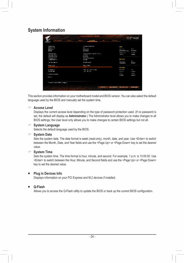
This section provides information on your motherboard model and BIOS version. You can also select the default language used by the BIOS and manually set the system time.
& Access Level Displays the current access level depending on the type of password protection used. (If no password is
set, the default will display as Administrator.) The Administrator level allows you to make changes to all BIOS settings; the User level only allows you to make changes to certain BIOS settings but not all.
& System Language Selects the default language used by the BIOS.
& System Date Sets the system date. The date format is week (read-only), month, date, and year. Use <Enter> to switch
between the Month, Date, and Year fields and use the <Page Up> or <Page Down> key to set the desired value.
& System Time Sets the system time. The time format is hour, minute, and second. For example, 1 p.m. is 13:00:00. Use
<Enter> to switch between the Hour, Minute, and Second fields and use the <Page Up> or <Page Down> key to set the desired value.
� Plug in Devices Info Displays information on your PCI Express and M.2 devices if installed.
� Q-Flash Allows you to access the Q-Flash utility to update the BIOS or back up the current BIOS configuration.

- 25 -
Boot
& Bootup NumLock State Enables or disables Numlock feature on the numeric keypad of the keyboard after the POST.
& CFG Lock Enables or disables the MSR 0xE2 function.
& Security Option Specifies whether a password is required every time the system boots, or only when you enter BIOS Setup.
After configuring this item, set the password(s) under the Administrator Password/User Password item. �Setup A password is only required for entering the BIOS Setup program. �System A password is required for booting the system and for entering the BIOS Setup program.
& Full Screen LOGO Show Allows you to determine whether to display the GIGABYTE Logo at system startup. Disabled skips the
GIGABYTE Logo when the system starts up.
& Boot Option Priorities Specifies the overall boot order from the available devices. Removable storage devices that support GPT
format will be prefixed with "UEFI:" string on the boot device list. To boot from an operating system that supports GPT partitioning, select the device prefixed with "UEFI:" string.
Or if you want to install an operating system that supports GPT partitioning such as Windows 10 64-bit, select the optical drive that contains the Windows 10 64-bit installation disc and is prefixed with "UEFI:" string.
& Fast Boot Enables or disables Fast Boot to shorten the OS boot process. Ultra Fast provides the fastest bootup
speed. & SATA Support
�Last Boot SATA Devices Only Except for the previous boot drive, all SATA devices are disabled before the OS boot process completes.
�All SATA Devices All SATA devices are functional in the operating system and during the POST. This item is configurable only when Fast Boot is set to Enabled or Ultra Fast.

- 26 -
& VGA Support Allows you to select which type of operating system to boot.
�Auto Enables legacy option ROM only. �EFI Driver Enables EFI option ROM.
This item is configurable only when Fast Boot is set to Enabled or Ultra Fast. & USB Support
�Disable Link All USB devices are disabled before the OS boot process completes. �Full Initial All USB devices are functional in the operating system and during the POST. �Partial Initial Part of the USB devices are disabled before the OS boot process completes.
This item is configurable only when Fast Boot is set to Enabled or Ultra Fast. This function is disabled when Fast Boot is set to Ultra Fast.
& NetWork Stack Driver Support �Disable Link Disables booting from the network. �Enabled Enables booting from the network.
This item is configurable only when Fast Boot is set to Enabled or Ultra Fast. & Next Boot After AC Power Loss
�Normal Boot Enables normal bootup upon the return of the AC power. �Fast Boot Keeps the Fast Boot settings upon the return of the AC power.
This item is configurable only when Fast Boot is set to Enabled or Ultra Fast.
& Mouse Speed Allows you to set the mouse cursor movement speed.
& Windows 10 Features Allows you to select the operating system to be installed.
& CSM Support Enables or disables UEFI CSM (Compatibility Support Module) to support a legacy PC boot process.
�Disabled Disables UEFI CSM and supports UEFI BIOS boot process only. �Enabled Enables UEFI CSM.
& LAN PXE Boot Option ROM Allows you to select whether to enable the legacy option ROM for the LAN controller. This item is configurable only when CSM Support is set to Enabled.
& Storage Boot Option Control Allows you to select whether to enable the UEFI or legacy option ROM for the storage device controller.
�Do not launch Disables option ROM. �UEFI Enables UEFI option ROM only. �Legacy Enables legacy option ROM only.
This item is configurable only when CSM Support is set to Enabled. & Other PCI devices
Allows you to select whether to enable the UEFI or Legacy option ROM for the PCI device controller other than the LAN, storage device, and graphics controllers.
�Do not launch Disables option ROM. �UEFI Enables UEFI option ROM only. �Legacy Enables legacy option ROM only.
This item is configurable only when CSM Support is set to Enabled.

- 27 -
& Administrator Password Allows you to configure an administrator password. Press <Enter> on this item, type the password, and
then press <Enter>. You will be requested to confirm the password. Type the password again and press <Enter>. You must enter the administrator password (or user password) at system startup and when entering BIOS Setup. Differing from the user password, the administrator password allows you to make changes to all BIOS settings.
& User Password Allows you to configure a user password. Press <Enter> on this item, type the password, and then press
<Enter>. You will be requested to confirm the password. Type the password again and press <Enter>. You must enter the administrator password (or user password) at system startup and when entering BIOS Setup. However, the user password only allows you to make changes to certain BIOS settings but not all.
To cancel the password, press <Enter> on the password item and when requested for the password, enter the correct one first. When prompted for a new password, press <Enter> without entering any password. Press <Enter> again when prompted to confirm.
NOTE: Before setting the User Password, be sure to set the Administrator Password first.
� Secure Boot Allows you to enable or disable Secure Boot and configure related settings. This item is configurable only
when CSM Support is set to Disabled. & Preferred Operating Mode
Allows you to select whether to enter Easy mode or Advanced mode after entering BIOS Setup. Auto enters the BIOS mode where it was last time.

- 28 -
Save & Exit
& Save & Exit Setup Press <Enter> on this item and select Yes. This saves the changes to the CMOS and exits the BIOS Setup
program. Select No or press <Esc> to return to the BIOS Setup Main Menu. & Exit Without Saving
Press <Enter> on this item and select Yes. This exits the BIOS Setup without saving the changes made in BIOS Setup to the CMOS. Select No or press <Esc> to return to the BIOS Setup Main Menu.
& Load Optimized Defaults Press <Enter> on this item and select Yes to load the optimal BIOS default settings. The BIOS defaults
settings help the system to operate in optimum state. Always load the Optimized defaults after updating the BIOS or after clearing the CMOS values.
& Boot Override Allows you to select a device to boot immediately. Press <Enter> on the device you select and select Yes
to confirm. Your system will restart automatically and boot from that device. & Save Profiles
This function allows you to save the current BIOS settings to a profile. You can create up to 8 profiles and save as Setup Profile 1~ Setup Profile 8. Press <Enter> to complete. Or you can select Select File in HDD/FDD/USB to save the profile to your storage device.
& Load Profiles If your system becomes unstable and you have loaded the BIOS default settings, you can use this function
to load the BIOS settings from a profile created before, without the hassles of reconfiguring the BIOS settings. First select the profile you wish to load and then press <Enter> to complete. You can select Select File in HDD/FDD/USB to input the profile previously created from your storage device or load the profile automatically created by the BIOS, such as reverting the BIOS settings to the last settings that worked properly (last known good record).