BIODEGRADABLE POLY(ESTER-URETHANE) SCAFFOLDS FOR...
147
BIODEGRADABLE POLY(ESTER-URETHANE) SCAFFOLDS FOR BONE TISSUE ENGINEERING A THESIS SUBMITTED TO THE GRADUATE SCHOOL OF NATURAL AND APPLIED SCIENCES OF MIDDLE EAST TECHNICAL UNIVERSITY BY AYSEL KIZILTAY IN PARTIAL FULFILLMENT OF THE REQUIREMENTS FOR THE DEGREE OF DOCTOR OF PHILOSOPHY IN BIOTECHNOLOGY SEPTEMBER 2011
Transcript of BIODEGRADABLE POLY(ESTER-URETHANE) SCAFFOLDS FOR...

BIODEGRADABLE POLY(ESTER-URETHANE) SCAFFOLDS
FOR BONE TISSUE ENGINEERING
A THESIS SUBMITTED TO
THE GRADUATE SCHOOL OF NATURAL AND APPLIED SCIENCES
OF
MIDDLE EAST TECHNICAL UNIVERSITY
BY
AYSEL KIZILTAY
IN PARTIAL FULFILLMENT OF THE REQUIREMENTS
FOR
THE DEGREE OF DOCTOR OF PHILOSOPHY
IN
BIOTECHNOLOGY
SEPTEMBER 2011

Approval of the thesis:
BIODEGRADABLE POLY(ESTER-URETHANE) SCAFFOLDS
FOR BONE TISSUE ENGINEERING
submitted by AYSEL KIZILTAY in partial fulfillment of the requirements for the
degree of Doctor of Philosophy in Biotechnology Department, Middle East
Technical University by,
Prof. Dr. Canan Özgen _____________________
Dean, Graduate School of Natural and Applied Sciences
Prof. Dr. İnci Eroğlu _____________________
Head of Department, Biotechnology
Prof. Dr. Nesrin Hasırcı _____________________
Supervisor, Chemistry Dept., METU
Prof. Julio San Roman _____________________
Co-Supervisor, CSIC, SPAIN
Examining Committee Members:
Prof. Dr. Aşkın Tümer _____________________
Dept. of Biology, Hacettepe University
Prof. Dr. Nesrin Hasırcı _____________________
Dept. of Chemistry, METU
Prof. Dr. Meral Yücel _____________________
Dept. of Biological Sciences, METU
Prof. Dr. İnci Eroğlu _____________________
Dept. of Chemical Engineering, METU
Assoc. Prof. Dr. Ayşen Tezcaner _____________________
Dept. of Engineering Sciences, METU
Date: 14.09.2011

iii
I hereby declare that all information in this document has been obtained and
presented in accordance with academic rules and ethical conduct. I also declare
that, as required by these rules and conduct, I have fully cited and referenced all
material and results that are not original to this work.
Name, Last name: Aysel Kızıltay
Signature:
iv
ABSTRACT
BIODEGRADABLE POLY(ESTER-URETHANE)
SCAFFOLDS FOR BONE TISSUE ENGINEERING
Kızıltay, Aysel
Ph.D., Department of Biotechnology
Supervisor: Prof. Dr. Nesrin Hasırcı
September 2011, 128 pages
During last decade, polyurethanes (PUs) which are able to degrade into harmless
molecules upon implantation have received a significant level of attention as a
biomaterial in tissue engineering applications. Many studies are focused especially on
development of PUs based on amino acid derivatives; however, there are only few
applications of amino acid based PUs in tissue engineering. In this study, a
biocompatible and biodegradable thermoplastic poly(ester-urethane) (PEU) based on L-
lysine diisocyanate (LDI) and polycaprolactone diol (PCL) was synthesized and used
for the preparation of two dimensional (2D) films and three dimensional (3D)
scaffolds. The resulting polymer was casted as 2D films for full characterization
purpose and it was found that it is highly elastic with modulus of elasticity ~12 MPa.
Surfaces of 2Ds were modified via micropatterning and fibrinogen coating to check the
material-cell interaction. The 3D scaffolds were obtained by salt leaching and rapid
v
prototyping (bioplotting) techniques. The 3D scaffolds had various pore size and
porosity with different mechanical strength. The bioplotted scaffolds had uniform pore
size of ~450 µm and exhibited higher compressive modulus (~4.7 MPa) compared to
those obtained by salt leaching (~147 kPa). Salt leached 3D scaffolds had
inhomogenous pore size distribution in the range of 5 µm - 350 µm and demonstrated
greatest degradation profile compared to 2D films and 3D bioplotted samples under
enzymatic condition. Rat bone marrow stem cells (BMSCs) were used to investigate
the biocompatibility of the polymer and suitability of fabricated scaffolds for
osteogenesis. Presence of micropatterns on 2D matrices did not show any influence on
osteoblastic function, but presence of fibrinogen enhanced cell attachment and
proliferation. All of the fabricated 3D PEU matrices supported proliferation,
osteoblastic differentiation and extracellular matrix (ECM) deposition with highest
osteoblastic activity on bioplotted scaffolds which confirmed by von Kossa staining
and EDX analysis. The results indicated that the synthesized PEU based scaffolds were
able to induce osteoblastic differentiation and mineralization of BMSC and therefore
these scaffolds can be good candidates to be used in bone tissue engineering.
Keywords: Bone tissue engineering, Polyurethane, Lysine, Rapid prototyping, Salt
leaching

vi
ÖZ
KEMİK DOKU MÜHENDİSLİĞİ İÇİN BİYOBOZUNUR
POLİ(ESTER-ÜRETAN) DESTEK YAPILAR
Kızıltay, Aysel
Doktora, Biyoteknoloji Bölümü
Tez Yöneticisi: Prof. Dr. Nesrin Hasırcı
Eylül 2011, 128 sayfa
Son on yılda, vücut içine yerleştirildikten sonra zararsız bileşenlere parçalanabilen
poliüretanlar (PU) biyomalzeme olarak doku mühendisliği uygulamalarında oldukça
dikkat çekmiştir. Birçok çalışma özellikle amino asit temelli PU’ların geliştirilmesine
odaklanmış olduğu halde, amino asit bazlı PU’ların doku mühendisliğine yönelik
uygulamaları çok azdır. Bu çalışmada, lisin diizosiyanat (LDI) ve polikaprolakton diol
(PCL) temelli biyouyumlu ve biyobozunur termoplastik bir poli(ester-üretan) (PEU)
sentezlenmiş, iki boyutlu (2D) ve üç boyutlu (3D) destek yapıların hazırlanmasında
kullanılmıştır. Elde edilen polimer tam karakterizasyon için 2D film olarak elde edilmiş
ve polimerin ~12 MPa’lık bir elastik modulüs değeriyle birlikte oldukça elastik bir
yapıya sahip olduğu bulunmuştur. 2D yapıların yüzeyleri, malzeme-hücre etkileşimini
incelemek amacıyla mikrodesenleme ve fibrinojen kaplama ile değiştirilmiştir. 3D
vii
iskele yapılar tuz uzaklaştırma ve hızlı prototiplendirme (bioplotting) teknikleriyle elde
edilmiştir. 3D iskele yapılar farklı gözenek boyutu ve mekanik dayanım göstermiştir.
Bioplotting tekniğiyle elde edilen iskele yapılar ~450 µm büyüklükte homojen gözenek
boyutuna sahip olup tuz uzaklaştırma tekniğiyle elde edilen yapılardan (~147 kPa) daha
büyük basma modulüsü (~4.7 MPa) göstermiştir. Tuz uzaklaştırma ile elde edilen 3D
iskele yapılar, 5 µm - 350 µm aralığında eşit olmayan gözenek boyutu dağılımına sahip
olup enzimli ortamda film ve bioplotting ile elde edilen yapılara göre daha hızlı
bozunma profili göstermiştir. Polimerin biyouyumluluğu ve elde edilen destek yapıların
osteogenesis için uygunluğunun araştırılmasında fare kemik iliği kök hücreleri (BMSC)
kullanılmıştır. 2D yapılar üzerinde mikrodesen varlığı, osteoblastik işlev üzerinde bir
etki göstermezken fibrinojen varlığı hücre yapışmasını ve çoğalmasını arttırmıştır. von
Kossa boyama ve EDX analiziyle doğrulanan sonuçlara göre, üretilen bütün 3D PEU
destek yapılar hücre çoğalmasını, osteoblastik farklılaşmayı ve hücre dışı matrisin
(ECM) birikmesini desteklemiştir ve en yüksek osteoblastik aktivite, bioplotting ile
elde edilen yapılar üzerinde görülmüştür. Sonuçlar, sentezlenen PEU temelli iskele
yapıların BMSC’lerin osteoblastik hücreye farklılaşmasını ve mineralizasyonunu
uyarabildiğini göstermiştir ve bu nedenle, bu iskele yapılar kemik doku mühendisliğine
yönelik kullanım için uygun adaylar olabilirler.
Anahtar Kelimeler: Kemik doku mühendisliği, Poliüretan, Lizin, Hızlı prototip, Tuz
uzaklaştırma

viii
To my family...

ix
ACKNOWLEDGEMENTS
I would like to express my special thanks to my supervisor Prof. Dr. Nesrin
Hasırcı for her continuous guidance, encouragement, motivation and support
during all the stages of my thesis. I sincerely appreciate the time and effort she
has spent to improve my experience during my graduate years.
I am also deeply thankful to Prof. Dr. Vasıf Hasırcı for his support, leadership
and guidance in METU-BIOMAT Biomaterials and Tissue Engineering
Research Group.
My sincere acknowledgements go to my thesis progress committee members,
Prof. Dr. Aşkın Tümer and Prof. Dr. Meral Yücel for their helpful comments
and suggestions throughout this thesis.
I am grateful to Prof. Dr. Julio San Roman, Dr. Angel M. Fernandez and for
their guidance during the stage of polymer synthesis and characterization
studies at CSIC, Madrid. Also, I am thankful to Dr. Alberto Gallardo for his
endless help and company in laboratory and outlife in Madrid. I am grateful to
all people in polymer department in CSIC.
I wish to thank Prof. Dr. Rui Reis for providing me a good opportunity to work
in his research laboratory. I would like to acknowledge Dr. Rui Amandi de
Sousa for his help during my experiments. I also would like to thank to all
members of 3B’s Research Group for their support during my stay in Portugal.

x
I deeply thank to special lab mates Tuğba Endoğan, Eda Ayşe Aksoy, Cantürk
Özcan, İsmail Doğan Günbaş, Taylan Özerkan, Elif Vardar, Cansel Işıklı,
Aysun Güney, Şeniz Uçar, Filiz Kara and other lab members of D-148 for the
good memories, continuous help and support during my experiments. I also
would like to thank my roommates, especially to Eylem Yalçınkaya, Mine
Kalkancı and Aydan Bahadır for their support and friendship during graduate
years.
I am thankful to Dr. Deniz Yücel and Dr. Halime Kenar who teached me cell
culture techniques and supported me throughout all the stages of my graduate
years.
I deeply thank all the members of METU-BIOMAT group, especially Dr. Pınar
Yılgör, Arda Büyüksungur, Albana Ndreu, Beste Kınıkoğlu and Hayriye
Özçelik. I also would like to thank Mr. Zeynel Akın for his endless technical
support throughout my research.
I would like to thank to METU Central Laboratory for characterization
analyses.
This study was supported by METU-BAP 2005-07-02-00-92 and FP6 European
Network of Excellence project EXPERTISSUES and these grants are gratefully
acknowledged. I also would like to acknowledge the support from TUBITAK
through projects TBAG 105T508 and 108T805, 104M432.
Finally, I would like to thank to my mother Fatma Kızıltay, my father Hilmi
Kızıltay and my brothers Murat and Şenol Kızıltay, for the love and patience
they have shown throughout all my life.
xi
TABLE OF CONTENTS
ABSTRACT .................................................................................................................... iv
ÖZ……. .......................................................................................................................... vi
ACKNOWLEDGEMENTS ............................................................................................ ix
TABLE OF CONTENTS ................................................................................................ xi
LIST OF TABLES ......................................................................................................... xv
LIST OF FIGURES ....................................................................................................... xvi
ABBREVIATIONS ....................................................................................................... xix
CHAPTERS
1. INTRODUCTION .................................................................................................... 1
1.1 Bone Physiology ................................................................................................ 1
1.1.1 Bone Composition and Structure ............................................................. 1
1.1.2 Extracellular Bone Matrix ........................................................................ 4
1.1.2.1 Mineral (Inorganic) Phase ....................................................... 5
1.1.2.2 Organic Phase .......................................................................... 6
1.1.3 Dependence of Bone Architecture on Anatomical Locations,
Age and Gender .................................................................................... 7
1.1.4 Bone Regeneration and Remodeling ........................................................ 8
1.1.5 Bone Grafts (Autologous, Allografts, Xenografts) .................................. 9
1.1.6 Classification of Tissue Response .......................................................... 10
1.1.7 Bone Graft Substitutes (BGS) ................................................................ 12
1.1.7.1 Human Bone Matrix and Demineralized Bone Matrix. ........ 12
1.1.7.2 Ceramic Biomaterials (Calcium Orthophosphates). .............. 13
1.1.7.3 Natural Coral and Other Marine Biomaterials. ..................... 14
1.2 Tissue Engineering of Bone ............................................................................ 15

xii
1.3 Biomaterials Used for Tissue Engineering Scaffolds ...................................... 16
1.4 Engineered Cells .............................................................................................. 21
1.4.1 Bone Morphogenetic Proteins and Osteogenic Supplements ................ 22
1.5 Fabrication Techniques in Scaffold Development .......................................... 23
1.5.1 Fiber Bonding Technique ....................................................................... 25
1.5.2 Solvent Casting and Particulate Leaching Techniques .......................... 25
1.5.3 Gas-Foaming Technique ........................................................................ 26
1.5.4 Freeze Drying ......................................................................................... 26
1.5.5 Electrospinning....................................................................................... 27
1.5.6 Melt Based Fabrication Techniques ....................................................... 27
1.6 Scaffold Fabrication with Designed Architecture ........................................... 28
1.6.1 Rapid Prototyping (RP) .......................................................................... 28
1.6.1.1 Melt-Dissolution Technique. ................................................. 29
1.6.1.2 Particle Bonding Technique. ................................................. 29
1.7 Surface Modification of Tissue Engineered Constructs .................................. 32
1.8 The Aim of This Study .................................................................................... 35
2. EXPERIMENTAL ................................................................................................. 37
2.1 Materials .......................................................................................................... 37
2.2 Synthesis of Lysine Based Polyurethane ......................................................... 37
2.3 Preparation of PEU Matrices ........................................................................... 39
2.3.1 Preparation of PEU Films ...................................................................... 40
2.3.2 Preparation of PEU Sponges .................................................................. 41
2.3.3 Fabrication of PEU Scaffolds by 3-D Plotting ....................................... 42
2.3.4 Modification of PEU Matrices with Oxygen Plasma ............................. 45
2.4 Characterization of Matrices ........................................................................... 45
2.4.1 Composition and Molecular Weight ...................................................... 45
2.4.2 Thermal Characterization ....................................................................... 45

xiii
2.4.3 Determination of Porosity and Pore Size Distribution of PEU
Matrices .................................................................................................. 46
2.4.4 Mechanical Properties of PEU Matrices ................................................ 47
2.4.5 Dynamical Mechanical Analysis (DMA) of PEU Films ........................ 48
2.4.6 Evaluation of In situ Degradation .......................................................... 48
2.4.7 Water Contact Angle Measurements...................................................... 49
2.5 In Vitro Studies ................................................................................................ 49
2.5.1 Isolation and Culture of Mesenchymal Osteoprogenitor Cells .............. 49
2.5.2 Cell Seeding and Culturing on PEU Matrices ........................................ 50
2.5.3 Microscopy and Image Analysis ............................................................ 51
2.5.3.1 Scanning Electron Microscopy. ............................................ 51
2.5.3.2 Fluorescent Microscopy. ....................................................... 51
2.5.4 Cell Proliferation .................................................................................... 51
2.5.5 Determination of Osteoblastic Differentiation ....................................... 52
2.5.5.1 Alkaline Phosphatase (ALP) activity. ................................... 52
2.5.5.2 Matrix Mineralization. ........................................................... 52
3. RESULTS AND DISCUSSION ............................................................................ 54
3.1 Characterization of PEU Matrices ................................................................... 54
3.2 Liquid State NMR, FTIR-ATR, GPC and Contact Angle Analyses ............... 54
3.3 Thermal Properties of PEU Matrices............................................................... 57
3.3.1 Tensile Test Results of PEU Films ........................................................ 60
3.3.2 Dynamical Mechanical Analysis (DMA) of PEU Films ........................ 62
3.4 Morphology of 3D PEU Matrices ................................................................... 65
3.5 Porosity and Pore Size Distribution of 3D PEU Matrices ............................... 68
3.5.1 Determination of Porosity ...................................................................... 68
3.5.2 Pore Size Distribution ............................................................................ 71
3.6 In situ Degradation Profiles of PEU Matrices ................................................. 74
3.7 Compressive Modulus of 3D PEU Matrices ................................................... 76

xiv
3.8 In Vitro Studies ................................................................................................ 79
3.8.1 In Vitro Cell Culture on 2D PEU Films ................................................. 79
3.8.1.1 Cell Morphology. .................................................................. 79
3.8.1.2 Cell Proliferation. .................................................................. 82
3.8.1.3 Osteoblastic Differentiation. ................................................. 84
3.8.2 In Vitro Cell Culture on 3D Scaffolds ................................................... 86
3.8.2.1 Surface Modification of 3D Scaffolds. .................................. 86
3.8.2.2 Cell Morphology on 3D Scaffolds. ....................................... 87
3.8.2.3 Cell Proliferation on 3D Scaffolds. ....................................... 90
3.8.2.4 von Kossa Staining. ............................................................... 91
3.8.2.5 SEM/EDX Imaging of Mineralization on 3D
Scaffolds. ................................................................................................ 95
3.8.3 Effect of Cell Proliferation on Compressive Properties of 3D
PEU Matrices ....................................................................................... 100
4. CONCLUSIONS .................................................................................................. 103
REFERENCES ............................................................................................................. 103
APPENDIX A Calibration Curve ................................................................................ 125
CURRICULUM VITAE .............................................................................................. 126

xv
LIST OF TABLES
TABLES
Table 1.1 Biochemical composition of bone .................................................................. 3
Table 1.2 Mechanical properties of various human bone tissues ................................... 4
Table 1.3 Matrix proteins of bone .................................................................................. 7
Table 1.4 Classification of implant material with respect to tissue response
they evoke .................................................................................................... 12
Table 2.1 Designation of 2D and 3D matrices prepared from PEU ............................. 39
Table 3.1 The molecular weight, heterogeneity index (HI) and water contact
angle values of SF ........................................................................................ 56
Table 3.2 Thermal data for different PEU matrices ..................................................... 59
Table 3.3 Tensile test parameters of PEU .................................................................... 61
Table 3.4 Tan δ peak magnitude and Tg values for PEU at different
frequencies ................................................................................................... 63
Table 3.5 Porosity of 3D scaffolds ............................................................................... 70
Table 3.6 Compressive modulus values of 3D scaffolds ............................................. 70
Table 3.7 Weight percentage of C, O, P and Ca elements on different scaffolds
seeded with BMSCs ..................................................................................... 98
Table 3.8 Change in compressive moduli of seeded 3D scaffolds by time ................ 101
xvi
LIST OF FIGURES
FIGURES
Figure 1.1 Schematic drawing of hierarchical structure of bone. ................................. 2
Figure 1.2 Illustration of urethane linkage formation ................................................. 20
Figure 2.1 Synthesis of poly(ester-urethane) from PCL diol and LDI. ....................... 38
Figure 2.2 Summary of experimental study ................................................................ 40
Figure 2.3 Schematic presentation of micropatterned polymeric film
preparation ................................................................................................ 41
Figure 2.4 Steps of salt leaching for porous foam fabrication. ................................... 42
Figure 2.5 Bioplotter instrument ................................................................................. 44
Figure 2.6 Plotting of melted PEU a) layer by layer, b) BP-B, c) BP-O ..................... 44
Figure 3.1 13
C-NMR spectrum of PEU and PCL diol. ............................................... 55
Figure 3.2 FTIR-ATR spectra of PEU film and PCL diol. ......................................... 57
Figure 3.3 DSC thermograms of PEU matrices. ......................................................... 59
Figure 3.4 TGA curves of PEU smooth film (SF) and bioplotted (BP-B)
scaffold. ..................................................................................................... 60
Figure 3.5 Representative stress–strain curve of the synthesized PEU film ............... 61
Figure 3.6 Tan δ versus temperature curve of PEU film at different frequency. ........ 64
Figure 3.7 Temperature dependency of the storage modulus for PEU film at
different frequency. ................................................................................... 64
Figure 3.8 Shifting of Tg at different frequencies. ...................................................... 65
Figure 3.9 SEM images of PEU scaffolds fabricated by Bioplotter. . ........................ 66
Figure 3.10 SEM images of PEU scaffolds prepared by freeze drying and salt
leaching. ........................................................................................... 67
xvii
Figure 3.11 Pseudo-coloured µ-CT images of PEU scaffolds produced by
Bioplotter a) Isometric, b) Side view. ....................................................... 71
Figure 3.12 Pore size distributions of freeze dried spongy scaffolds. a) Freeze
dried (SP0), b) Low salt leaching ratio (SP5), c) High salt leaching
ratio (SP10). .............................................................................................. 73
Figure 3.13 Degradation profiles of 2D films and 3D scaffolds in PBS with
0.18 U/mL of lipase (n=3). ........................................................................ 75
Figure 3.14 Representative load-deformation curves of freeze dried and salt
leached spongy scaffolds. .......................................................................... 77
Figure 3.15 Representative load-deformation curve of bioplotted scaffolds ................ 77
Figure 3.16 Fluorescence images of BMSCs seeded on a) MF-Fn, b) MF. Actin
microfilaments (green) were visualized by FITC-labeled
phalloidin. Cell nuclei were visualized by DAPI (blue). .......................... 81
Figure 3.17 SEM images of BMSCs seeded on a) SF, b) MF. c) and d) Closer
views of alignment within the groove (day 3). ......................................... 82
Figure 3.18 Cell proliferation of BMSCs on PEU films and tissue culture plate
(control) quantified using Alamar Blue assay on days 1, 7, 14 and
21 (n=3) ..................................................................................................... 84
Figure 3.19 ALP activity of BMSCs per sample at the end of three weeks (n=3) ........ 85
Figure 3.20 Fluorescence microscopy images showing mineralization achieved
by osteoblasts on polymeric films at the end of three weeks. ................... 85
Figure.3.21 Fate of drop of cell suspension on a) untreated and b) plasma
treated scaffolds. Photo was taken right after the dropping. .................... 87
Figure 3.22 Cell attachment and spreading on salt leached spongy scaffolds on
day 1. a) SP5 b) SP10. Images on the right colons are the high
magnification of corresponding images. ................................................... 88
Figure 3.23 SEM micrographs of the seeded bioplotted scaffolds showing the
interaction between the cells and scaffold fibers on a) day 1, b)

xviii
day 3, c) day 7. Images on the right colons are the high
magnification of the corresponding images. ............................................. 89
Figure 3.24 Proliferation of BMSCs on 3D scaffolds (n=3). ........................................ 91
Figure 3.25 von Kossa staining of mineralization on salt leached scaffold after
5weeks of culture a) Unseeded negatif control b) SP5 and b) SP10
(Scale bar = 100 µm). Arrow indicates mineralized nodules. ................... 93
Figure 3.26 von Kossa staining of mineralization on bioplotted scaffolds after 5
weeks of culture. a) Unseeded negatif control b) Focus on upside
fiber surface, b) Focus on underside fiber surface (Scale bar = 200
µm, insets =100 µm). ................................................................................ 94
Figure 3.27 SEM micrographs showing ECM deposition and mineralisation on
salt leached scaffolds after 5 weeks of culture. a-b) on SP5, c-d)
on SP10. Arrows indicate mineral deposits. ............................................. 96
Figure 3.28 SEM micrographs showing ECM deposition and mineralisation on
bioplotted scaffolds after 35 days of culture. a) Top view, b) and
c) Side view of ECM deposition. .............................................................. 97
Figure 3.29 EDX measurement for the detection of mineralization on a) SP5,
b) SP10), c) BP-O on day 1 (left column) and on day 35. ......................... 99
Figure 3.30 Compressive moduli of seeded salt leached scaffolds on day 1 and
on day 35 under wet conditions............................................................... 102
Figure 3.31 Compressive moduli of seeded bioplotted scaffolds on day 1 and
on day 35 under wet conditions............................................................... 102

xix
ABBREVIATIONS
2D Two Dimensional
3D Three Dimensional
ALP Alkaline Phosphatase
ATR Attenuated Total Reflectance
BGS Bone Graft Substitute
BSA Bovine Serum Albumin
BMSC Bone Marrow Stem Cell
DMA Dynamic Mechanical Analysis
E Young’s Modulus
E′ Storage Modulus
EAB Elongation at Break
SEM Scanning Electron Microscope
ECM Extracellular Matrix
Fn Fibrinogen
FTIR Fourier Transform Infrared Spectroscopy
GPC Gel Permeation Chromatography
Mn Number Average Molecular Weight
Mw Weight Average Molecular Weight
MW Molecular Weight
NMR Nuclear Magnetic Resonance
PBS Phosphate Buffer Saline
PEU Poly (ester-urethane)
SEM Scanning Electron Microscope
Tg Glass Transition Temperature
Tm Melting temperature

1
CHAPTER 1
INTRODUCTION
1.1 Bone Physiology
Bone tissue is responsible for various functions in the body, including structural
support, mineral storage, and physiological functions such as the formation of blood
vessels [1]. Normal bone formation is a prolonged process which is regulated carefully
and involves sequential growth-regulatory steps. The physiology of bone involves a
complex interrelation of cellular, molecular and systemic components. Bone is
continuously remodeled tissue where mineral resorption and deposition take place
within a balance as a response to mechanical and molecular influences [2].
1.1.1 Bone Composition and Structure
Bone is a composite material, composed of extracellular matrix (inorganic and organic
components) and cells, which are osteoblasts (bone-forming cells), osteoclasts (bone-
destroying cells) and osteocytes, (bone-maintaining cells). Bone is a hierarchically
structured tissue where its mechanical properties depend on its architecture at all levels
of hierarchy (Figure 1.1). At the macroscopic level, human and mammalian bones are
classified into two types of osseous tissue, namely cortical bone (also known as
compact bone) and cancellous or spongy bone (also known as trabecular bone).
Compact bone tissue is dense and looks smooth and homogenous with canals and
passageways, while spongy bone composed of trabeculae with much open space
between the trabeculae filled with bone marrow [3]. Cortical bone is found primarily in
the shaft of long bones and the outer shell around cancellous bone. Cancellous bone is
found within cortical tissue, in medullary cavities at the ends of long bones, in the

2
interior of short bones mainly in the vertebrae [4]. Cancellous and cortical bone have
different anatomical features but identical cell types and a similar remodeling cycle [5].
At the sub-microscopic level, layers of parallel collagen fibrils (lamellae) surround a
central hole in a structure known as an osteon where bone undergoes remodelling. This
lamellar structure of the bone matrix gives fracture toughness. At the lowest level,
mineralized collagen fibrils gather into bundles named as fibril arrays where calcium
phosphate (hydroxyapatite) nanocrystals are embedded into these collagen fibrils
increasing their stiffness, but decreasing their fracture strain. Mechanical properties of
collagen fibrils depend on the amount of mineral particles and their arrangement within
the fibrils [6]..
Figure 1.1. Schematic drawing of hierarchical structure of bone [4].

3
Structurally, the hard tissue is composed of four phases: collagen fibers, calcium-
phosphate rich mineral, organic substances and water: 60% inorganic elements, 5%
minerals, 9% water and 25% organic bone matrix and ground substances (proteins,
polysaccharides and mucopolysaccharides), where the relative fractions of each vary
from bone to bone, as well as on age, sex and anatomical location within the body
[7,8]. Biochemical composition of bone is given in Table 1.1. Beside the main bone
cells, other cell types like endothelial cells, fibroblasts, lining cells and stem cells are
present in bone tissue.
The mineral homeostasis of the body is regulated by the action of bone cells together
via hormonal and mechanical stimuli. Osteoblasts are present in the interior and the
periphery surface of the bone. They activate the mineralization process by synthesizing
alkaline phosphatase enzyme. Osteoblasts are the final form of cells as a result of stem
cell differentiation in the bone marrow. After three months, they become flat in shape
and turn into lining cells which are metabolically inactive and very few of them (~15%)
turn into osteocytes.[9].
Table 1.1. Biochemical composition of bone
Inorganic part Organic part
Hydroxyapatite [HAp-Ca10(PO4)6(OH)2] Collagen type I
Minerals (sodium, magnesium,
other traces)
Non-collagenous proteins, morphogenetic
proteins, serum proteins
Carbonates Polysaccharides, lipids, cytokines
Citrates Primary bone cells (osteoblasts, osteocytes,
osteoclasts)
Water -

4
The cortical bone differs from cancelleous bone by structurally and functionally. The
cortical part of bone is responsible for mechanical and protective functions, whereas
cancellous bone mostly takes part in metabolic functions. Both structural and metabolic
aspects are related to the properties of mineralised extracelluar matrix [10]. Thus, it is
important to understand hard tissue formation and mineralization processes in bone in
order to mimic the natural bone tissue in vitro by tissue engineering attempt.
As mentioned before, the composition of bone differs between bone types, where
cancellous bone is much weaker than cortical bone. The enamel of teeth is the hardest
material in the human body due to its high mineral content (~95%) [8]. The mechanical
properties of various bone tissues are included in Table 1.2.
Table 1.2. Mechanical properties of various human bone tissues
Osseous tissue Elastic modulus (GPa) Tensile strength (MPa)
Cortical bone 17.7 133
Cancellous bone 0.30 15
Enamel 85 11.5 transverse, 42.2 parallel
Dentine 32.4 44.4
1.1.2 Extracellular Bone Matrix
Mesenchymal tissues like cartilage, bone, tendon, ligament and other connective tissues
are fabricated by highly differentiated cells which produce unique extracellular
matrices (ECMs) that finally predominate and give the characteristics of a tissue. Cells
are organized in the ECM which provides structural support and cope with different
loads via various mechanisms. In elder people collagen and proteoglycan structure of
5
the ECMs are comparatively denser which are responsible for mechanical and
functional characteristics of tissues [11]. The extracellular matrix is essential for some
type of cells for their specific functions.
The major solid components of human bone are collagen, mainly type I collagen
(organic matrix), and hydroxyapatite (inorganic matrix) (a natural ceramic, also found
in teeth) [12]. Collagen, apatite mineral and water are responsible for the main structure
of the bone. Collagen fibrils form a microenvironment which favours apatite nucleation
[13]. The composition of the mineral phase is mainly calcium (Ca2+)
and phosphate (PO
3
4 ) and a low amount of carbonates (CO 2
3 ), sodium (Na) and magnesium (Mg) [14].
Mineral part of bone is similar to hydroxyapatite [(Ca10(PO4)6(OH)2], as shown by X-
ray diffraction analysis.
1.1.2.1 Mineral (Inorganic) Phase
Calcium hydroxyapatite (HAp) is a mineral salt of mostly calcium phosphates in a
crystalline structure and constitute the inorganic part of bone. It is responsible for the
hardness of the bones. Hydroxyapatite crystals are organized within collagen fibrils. In
mature bone, minerals are associated with collagen fibrils; HAp crystals are aligned in
the direction of collagen fibrils as well as they are located in an ordered manner in
channels or grooves formed by neigboring gaps within the collagen network [15,16].
The mineral phase is important in the sense of mechanical properties, since mineral part
provide stiffness and strength to the bone. Therefore, mineral loss would lead to
decrease of modulus and strength of bone, which increase the risk of bone fracture. In
addition, orientation of crystals within ECM determines the anisotropy property of the
bone [17], the property of being directionally dependent that is physical and
mechanical properties differ with orientation.
6
1.1.2.2 Organic Phase
Type I collagen protein is the major component (over 90%) of organic matrix. It
provides strength and flexibility, as well as space for nucleotion of apatite crystals.
Collagen molecules are arranged as fibrils in a staggered fashion where crosslinks
connecting the C-terminal of a molecule to the N-terminal of neighboring one. These
crosslinks affect the mechanical behavior of bone by organizing fibrillation and
involving in mineralization process. Beside collagen type I, organic phase of bone
contains other structural proteins, proteoglycans and hyaluronan; and specialized
multiadhesive proteins. Types of bone matrix proteins are tabulated in Table 1.3. Every
tissue contains its own type of ECM specialized for its particular function [18]. The
amount of specific components varies according to the function of the tissue. The ECM
has received attention because of its importance in cell-to-cell signaling [19], wound
repair [20], and tissue functions [21]. It is an active and dynamic structure that conducts
vital regulatory signals between the cells, , influence gene expression at the cellular
level [22]. ECM components regulate mineralization, stock growth factors and protect
them against deactivation or destruction [23].
7
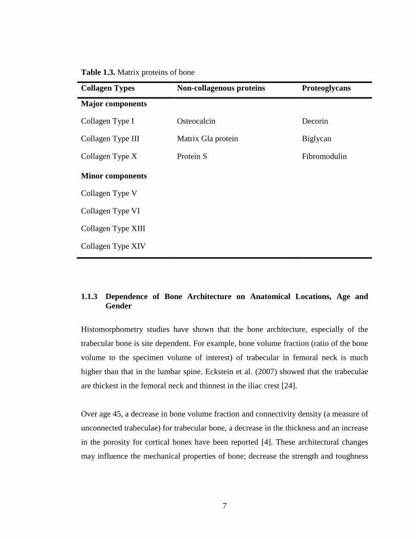
Table 1.3. Matrix proteins of bone
Collagen Types Non-collagenous proteins Proteoglycans
Major components
Collagen Type I Osteocalcin Decorin
Collagen Type III Matrix Gla protein Biglycan
Collagen Type X Protein S Fibromodulin
Minor components
Collagen Type V
Collagen Type VI
Collagen Type XIII
Collagen Type XIV
1.1.3 Dependence of Bone Architecture on Anatomical Locations, Age and
Gender
Histomorphometry studies have shown that the bone architecture, especially of the
trabecular bone is site dependent. For example, bone volume fraction (ratio of the bone
volume to the specimen volume of interest) of trabecular in femoral neck is much
higher than that in the lumbar spine. Eckstein et al. (2007) showed that the trabeculae
are thickest in the femoral neck and thinnest in the iliac crest [24].
Over age 45, a decrease in bone volume fraction and connectivity density (a measure of
unconnected trabeculae) for trabecular bone, a decrease in the thickness and an increase
in the porosity for cortical bones have been reported [4]. These architectural changes
may influence the mechanical properties of bone; decrease the strength and toughness

8
off the bone tissue. The most age-related structural change is decrease of bone volume
fraction in trabecular bone [25] and increase of porosity in cortical bone [26].
Architectural differences have been indicated between men and women; women being
more susceptible to osteoporosis. Architectural differences are more severe in women
with increasing age than in men. In postmenopausal women, trabecular matrix show
higher tendency to disconnect than men at same age. In addition, women usually have
thinner trabeculae at younger ages; therefore have higher risk of microstructural
damages with increasing age than men [27].
1.1.4 Bone Regeneration and Remodeling
One of the unique aspects of bone is that old tissue is continually being replaced with
the new tissue; this process is called bone remodeling. Bone is one of the body’s tissues
that have the ability to regenerate itself after a partial damage. However, bone itself
cannot heal a serious break or tumor lesions. Thus, a bone substitute is required to fill
defected bone tissue area. Bone failure is commonly seen in elder people. Joint diseases
and osteoporosis related fractures display important chronic conditions in people over
65 and women over 50, respectively. It is indicated that 25% of health espending in
developing countries will be spent on trauma-related care by the end of the 2010.
Beside, many children are suffering from crippling diseases and skeletal deformities
[28] and large bone defects, as observed after bone tumor resections require surgical
treatment [29]. Currently, bone grafting procedures are employed to promote the
healing of fracture and the repairing of other bone defects. Autografts (tissue graft
within the same individual), allografts (tissue graft between two individuals of same
species) and synthetic biomaterials like metallic, ceramic, polymer or composite are the
preferred bone substitutes in clinical practice.
9
Osteoblasts and osteocytes (differentiated osteoblasts) are bone forming cells
originated from pluripotent mesenchymal progenitor cells. Osteoblasts secrete bone
matrix and organic proteins such as collagen type I, osteopontin, osteocalcin etc. and
alkaline phosphatase (an indicator of bone cell function). Osteocytes are osteoblasts
which entrapped within the bone matrix. They secrete osseous growth factors such as
insulin like growth factor and tissue growth factor β which promote osteoblastic
differentiation. Immature osteoblasts do not secrete calcium, but mature osteoblasts do
[30]. It has been shown that three different growth phases undergo after osteoblasts
adhere to a material surface in vitro which are proliferation and synthesis of ECM,
development and maturation of ECM and ECM mineralization.
1.1.5 Bone Grafts (Autologous, Allografts, Xenografts)
Bone tissue failure like bone fractures and damages come out as a result of various
situations like trauma, surgery, infection, defects and aging. Bone grafts are bone
material that is isolated from another part of the body in order to help healing of
defective bone tissue or promote its function. Bone materials may be obtained from the
patient himself, from a donor or from an animal source. Bone grafts that are taken
directly from another skeletal part of the patient and transferred into another site of his
or her own bones are called autologous bone grafts (autografts), or bone autografts. A
portion of bone is usually harvested from iliac crest, tibia, fibula, and scapula or, in the
case of craniomaxillofacial reconstruction, the symphysis, maxillary tuberosity,
mandibular retro-molar area, or zygoma [31]. Generally, autografts are gold standard
for bone grafts due to their advantages like excellent incorporation of the graft, lack of
disease transmission, and absence of an immune rejection response. They are more
tolerable and effective, since they contain high amount of the patient’s own osteoblast
progenitor cells and bone morphogenetic proteins (BMPs). Autograft bone provides a
strong framework for the new bone to grow into. The drawbacks of autografts are the
need of an additional surgery (extra pain and discomfort for the patient), hematoma,

10
infection, increased operation time and cost, morbidity at the donor site and limited
availability of sufficient bone [32,33]. Bone graft that comes from another person is
called allograft bone. Allograft bone usually comes from bone banks that harvest the
bone from cadavers. Allografts, like autografts, provide a matrix for the new bone to
grow through it. The advantages of allograft bone are availability in high amount, the
elimination of second surgery, lack of pain and donor site morbidity and relatively less
time consuming. Disadvantages of allograft bone are the slight risk of disease
transmission, tissue rejection and a less potency since they do not contain proteins and
live cells which are removed during the cleaning and disinfecting processes [34].
Despite the benefits of autografts and allografts, the limitations and drawbacks of each
required the development of alternatives. Especially, there is an increasing demand for
synthetic bone graft products free from the limitations of supply, consistency, and
disease.
Various materials have been examined for their potential uses in place of the autografts
or allografts. Natural and synthetic polymers, ceramics, and composites either alone or
in combination with other materials have been widely investigated for this purpose. In
some strategies, growth factors and/or cells are incorporated to the material(s).
Although most of the available substitutes provide an alternative solution, none of them
yet possess all the benefits of one’s own bone. For the last decades, investigators have
focused on the development of novel bone graft substitutes which stimulate bone
healing and provide a strong and biocompatible matrix for the new bone formation [35-
37].
1.1.6 Classification of Tissue Response
All materials intended for use in humans as biomaterials, medical devices, or
prostheses undergo tissue responses when implanted into the body [38]. When

11
developing new material(s), it is important to have idea about the host response of the
material(s). Materials that evoke minimum response when contact with tissues or body
liquids are called biomaterials. Ideally, biomaterials should be biocompatible, meaning
do not provoke any undesired reaction within the body. Biocompatibility of an implant
is defined as the ability of a biomaterial to perform with an appropriate host response in
a specific application. Several factors influence an implantable material’s
biocompatibility. Surgical procedure, material-cell interfacial interactions, toxicology,
biodegradation, implant movement, mechanical properties, site of implantation,
sterilization and design, and construction are some of them [39]. An important issue of
host response is the formation of a structural and biological bond between the material
and host tissue. If the material is not biocompatible, systemic or local tissue reactions
will occur [8]. Implant materials are generally categorized according to their potential
risk of biological response that they induce when implanted (Table 1.4). The series of
tissue response initiated by the surgical procedure, as well as by the introduced
material. If the material is toxic, it causes death of the surrounding cells and tissue
mostly due to the release of soluble products. Bioinert materials are biocompatible
materials and do not induce formation of biological bond between implants and the
tissue. Bioactive materials can form biological and chemical bonds in the early stages
of implantation period. Bioresorbable materials are the ones which gradually resorbed
before they totally disappear and eventually replaced by the new coming tissue. There
is no material that behaves as totally inert. When a material is implanted, it is
recognized as a foreign matter and tried to be eliminated by the body. If the foreign
body could not be eliminated by macrophages, then the next step of this process is the
isolation of the implant by surrounding it with a capsule. Depending on the surface
area, shape and physicochemical properties of the material, blood cells of the immune
system and/or coagulation system are activated in order to protect the body against the
foreign matter. Most biomaterials display fibrous encapsulation where initially a thin 1–
3 mm-thick loosely organized capsule-like fibrous layer is formed on the surface of the
implant in order to isolate the implant from the living part of the body. The thickness of
12
the fibrous layer formed depends on chemical reactivity (inertness) and the relative
motion between the implant and tissue [40]. A thicker layer formation is induced by
more reactive materials, such as metals that undergo corrosion or polymer containing
residual monomers that may be leached under physiological conditions in order to
isolate the source of irritation. The immune responses to nonresorbable
(nondegradable) or resorbable (degradable) materials are similar initially; but as tissue
interacts with the degrading material surface and/or released degradation products, the
responses start to differ from each other. Nonresorbable biomaterials barely induce
inflammatory response or cause clot formation, where resorbable ones left the body
after a mild inflammation, generally via hydrolysis [41].
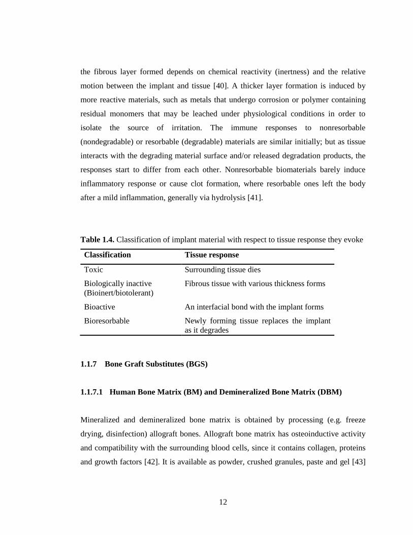
Table 1.4. Classification of implant material with respect to tissue response they evoke
Classification Tissue response
Toxic Surrounding tissue dies
Biologically inactive
(Bioinert/biotolerant)
Fibrous tissue with various thickness forms
Bioactive An interfacial bond with the implant forms
Bioresorbable Newly forming tissue replaces the implant
as it degrades
1.1.7 Bone Graft Substitutes (BGS)
1.1.7.1 Human Bone Matrix (BM) and Demineralized Bone Matrix (DBM)
Mineralized and demineralized bone matrix is obtained by processing (e.g. freeze
drying, disinfection) allograft bones. Allograft bone matrix has osteoinductive activity
and compatibility with the surrounding blood cells, since it contains collagen, proteins
and growth factors [42]. It is available as powder, crushed granules, paste and gel [43]

13
and can be injected through a syringe [44]. Mineralized allograft contains
hydroxyapatite which provides osteoconductivity and mechanical strength. DBM is less
immunogenic compare to BM [45]; but has lower mechanical strength since it does not
contain minerals [46]. Because of their osteoconductive and osteoinductive properties,
BM and DBM have been used for the regeneration of orthopedic, dental and
craniofacial injuries, defects or abnormalities [45]; mostly combined with other carrier
materials like calcium sulfate, hyaluronic acid and glycerol [47,48]. There are various
commercially available DBMs which have been demonstrated to have different
biological properties for a specific application [49].
1.1.7.2 Ceramic Biomaterials (Calcium Orthophosphates)
Calcium phosphate based ceramic materials seem to be noticeable as bone substitutes
due to their excellent strength, biocompatibility and osteoinductive properties. This is
because inorganic part of mammalian calcified tissues (bone and teeth) consists of
calcium orthophosphates [50]. Materials such as Bioglass, β tricalcium phosphate (β-
TCP), calcium sulphate (CS), hydroxyapatite (HAp) and biphasic calcium phosphate or
mixtures of these have been developed in bulk form or as granules as bone substitutes
in dentistry as well as orthopedic and reconstructive surgery [51]. This group of
materials exhibit high level of biocompatibility and osteoconductivity and binds
directly to bone tissues. Of the various calcium phosphates, HAp has received
considerable attention because its mineral composition [Ca10(PO4)6(OH)2] is close to
natural bone. However, due to its less solubility compared to other calcium phosphates
(e.g. β-TCP), it remains in the body longer and impedes new bone replacement [52].
Different calcium based compounds have various Ca/P ratio. For example, Ca/P ratio
for TCP and HAp is 1.5 and 1.67, respectively. Ca/P ratio of less than 1.0 is not
biomedically important. It has been stated that nonstoichiometric HAp shows better
osteoconduction property [53]. The bioceramics have also been used to coat the gliding
surfaces of artificial joints with the aim of providing bonding between the implant and

14
the native bone to enhance implant integration. Other ceramics like alumina and
zirconia are used for wear applications in joint replacements. When implanted,
bioceramics are not encapsulated by fibrous tissue as many others do [40]. However,
their mechanical and elastic properties do not resemble of the natural tissue properties,
since scaffolds made of calcium orthophosphates have a low elasticity, high brittleness,
poor mechanical strength especially in load-bearing sites, and low mechanical
reliability and fracture toughness. Moreover, generally it is difficult to form calcium
orthophosphates into the desired shape [54]. In the last decade, researchers have
developed biocomposites or biphasic calcium phosphate (BCP) by combining the HAp
with bioinert ceramics like alumina and zirconia to improve toughness and strength of
HAp. In some studies, BCP was formed with various ratio of HAp: TCP to obtain
desired properties. Nevertheless, none of these HAp-based composites showed superior
mechanical, physical and degradability properties.
1.1.7.3 Natural Coral and Other Marine Biomaterials
Marine biomaterials like coral, chitosan and sponge skeleton etc. are among the bone
substitutes. Corals are a broad group of marine invertebrate animals consist of a
mineral skeleton, mainly calcium carbonate in the structural form of aragonite with
impurities such as Sr, Mg and F ions, and an organic matrix [55]. The skeletons of
certain corals have been used as bone graft substitutes to treat various bone related
problems in humans [56] and in scaffolding for bone tissue engineering due to their
porous, osteoconductive and biodegradable properties [57]. Properties like 3D
structure, porosity, pore interconnections, and inorganic composition make the natural
coral suitable for bone tissue regeneration; however lack of osteoinductivity and
osteogenesis is major drawback to its use [56].
Chitosan is an amino-polysaccharide obtained by alkaline deacetylation of chitin which
is natural component of naturally found in shrimp or crab shells. It has a wide use in

15
biomedical field due to its biocompatible, biodegradable, osteoconductive and
antibacterial properties. Alone chitosan is not useful as a bone substitute due to its very
low mechanical strength. Thus, it has been used in combination with inorganic
materials like HAp and calcium phosphate in order to enhance biologic activity, and
decrease the inflammation caused by the leakage or migration of inorganic particles
[58].
1.2 Tissue Engineering of Bone
To overcome the limitations faced with conventional therapies used to treat bone tissue
defects or diseases, bone tissue engineering has been promoted as a new alternative to
regenerate bone tissue. In bone tissue engineering approach, cells capable of osteogenic
activity and osteoinductive signal molecules are combined with an appropriate material
[59]. For bone regeneration; a morphogenetic signal, responsive host cells that will
respond to the signal, a suitable carrier that can deliver the signal to specific locations
and can serve as matrix for the growth of the host cells, and a viable well vascularized
host bed are needed [60]. Two concepts are important for regeneration:
osteoconduction and osteoinduction. An osteoconductive material is one which allows
growth of bone on its surface or within its structure (e.g. down into pores, channels).
Osteoinduction is defined as the ability to cause pluripotential cells, from a nonosseous
environment to differentiate into chondroctyes and osteoblasts. Osteoinduction is the
ability of a material to allow repair in a location that would normally not heal if left
untreated [61]. The current trend in bone tissue engineering is to develop biodegradable
materials which temporarily support the bone tissue at the same time stimulating its
regeneration in such a way that this, temporary matrix disappears as the bone renew
itself. The biodegradable materials act as cell carriers and generally referred as
scaffolds [62]. For bone tissue engineering to succeed, there are some key factors
which the scaffolding biomaterials should provide [63]. These are summarized as
follows:

16
- Biocompatability: Lack of immnune response. Neither material itself nor the
degradation products should not be toxic, allergic or carcinogenic,
- Osteoconductivity: Material should have sufficient porous interconnected structure
for the cells to attach proliferate and migrate through the scaffold structure, for the
delivery of nutrients, growth factors, for penetration of new vessels and removal of
wastes,
- Osteoinductivity: Material should possess essential proteins and growth factors that
induce mesenchymal stem cells and other osteoprogenitor cells toward the
osteoblast lineage,
- Osteointegrity: Newly constituted mineralized tissue should be able to form an
intimate bond with the implant material,
- Mechanical match: Material should have similar mechanical properties that are
consistent with the tissue they are replacing.
Additionally, the material should:
- Have the desired surface properties to allow cell attachment, proliferation and
differentiation,
- Degrade with a certain rate proportional to the regrowth of new tissue,
- Be easily processed into 3D constructs in a well-controlled and reproducible
manner.
1.3 Biomaterials Used for Tissue Engineering Scaffolds
Scaffolds are main components of tissue engineering policies since they provide an
architectural texture in which extracellular matrix, cell–cell and growth factor
interactions take place to provide matrices for tissue regeneration [64]. In the sense of
bone tissue engineering, osteogenesis is highly dependent on the substrate carrier used,
which has to provide a suitable environment into which bone cells can migrate before
proliferating, differentiating and depositing bone matrix [65]. The substrate must have
specific physicochemical characteristics (e.g. surface free energy, charge,

17
hydrophobicity, etc.) and specific geometry (e.g. three dimensional and interconnected
porosity). Choosing the suitable materials for scaffold fabrication is very critical. The
materials used must be safe, not cause excessive immune responses, the bulk and
degradable products must be biocompatible and clearable by the body (resorption rate
must meet with the new bone formation rate) [66]. Besides, the scaffolds must be
osteoconductive, suitable for manufacturing techniques that generate high surface area
porous structures and sterilizable and handable during operation [67]. Generally, it has
been stated that scaffolds designed for bone tissue engineering purposes should possess
good mechanical properties in order to bear mechanical loading [68,69]. However,
some investigators believe that this requirement is not necessary, since the main
function of a scaffold is to support bone ingrowth and not to sustain mechanical loading
[70].
Polymers (macromolecules) are the main materials used for scaffold preparation in
various tissue engineering applications. Polymers can be obtained with different
molecular weight, polydispersity, crystallinity and thermal transitions which provide
various mechanical strength and flexibility. The surface hydrophobicity and
crystallinity of the polymers can affect cell morphology. Change of surface chemistry
will affect cell spreading or cell affinity for the surface, which can also cause changes
in phenotypic expression.
Polymers used for scaffold fabrication are either synthetic polymers or derived from
natural sources. Natural polymers are advantegous in the sense of having biological
recognition sites which enhance initial cell attachment and function. Most commonly
used natural polymers for bone tissue engineering include polysaccharides (e.g.
chitosan, alginate and hyaluronan) and proteins (e.g. collagen, gelatin, silk fibroin and
elastin). However, certain disadavantages of natural polymers restricted their use in
tissue engineering, which are weak mechanical properties, biodegradability, limited
availability, possible immunogenicity and risk of pathogenic impurities [63]. Generally,
18
natural polymers are combined with other synthetic polymers or ceramics to form a
composite material [71] having the advantageous of both natural and synthetic
materials or used in preparation of drug delivery systems [72].
Synthetic polymers are very attractive materials for bone tissue engineering
applications due to their advantegous properties like mechanical strength,
degradability, batch to batch consistency and microstructure. In contrast to metals and
ceramics which are also widely used as bone substitutes, polymers offer an extend
design flexibility since their composition and structure can be easily tailored for a
specific application [72]. Their biodegradation rate can be controlled through molecular
design. Some polymers are susceptible to hydrolytic degradation while some others can
degrade by cellular or enzymatic activity. The most commonly used synthetic polymers
for bone tissue engineering are listed below:
- Aliphatic (α-hydroxy) polyesters including poly(glycolic acid) (PGA), poly(L-lactic
acid) (PLLA), and their copolymers poly(lactic acid-co-glycolic acid) (PLGA).
- Poly(ε-caprolactone) (PCL)
- Poly(hydroxy butyrate) (PHB)
- Poly(1,4-butanediol succinate) (PBS)
- Poly(propylene fumarate) (PPF), degrade through hydrolysis of the ester bonds
similar to glycolide and lactide polymers
- Polyurethanes
- Polyphosphazenes
- Polyanhidrides
- Poly(ortho esters)
The aliphatic (α-hydroxy) polyesters have FDA approval for certain human use. They
degrade through hydrolysis of ester bonds. Their degradation rate can be altered to last
from several weeks to several years by changing the chemical composition,
19
crystallinity, molecular weight and molecular weight distribution. Although they are
widely used in bone tissue engineering, there are still ongoing researchs to enhance
their functionality.
Among the wide polyester family, polyurethanes are one of the most popular group of
biomaterials used for the development of medical devices [73]. Due to their versatility
in chemical, physical and mechanical properties, and moderately good
biocompatibility, they have a broad range of uses and applications varying from textiles
[74] to medical products like blood-contact materials [75,76], heart valves [77], cardiac
pacing leads [78], ureteral stents [79], bone implants [80], controlled release devices
[81] and so on.
Traditionally, PUs have been aimed as long-term implant materials for which
biodegradation was not desired [73]. Since toxic products can be released upon
degradation of polyamines associated with conventional isocyanates, their use as
absorbable biomaterials have been limited [82]. Degradation products of polyurethanes
based on diisocyanates such as 4,4’methylenediphenyl diisocyanate (MDI) and toluene
diisocyanate (TDI) are reported to be carcinogenic and mutagenic [83,84]. Therefore,
in the synthesis of degradable PUs, aromatic isocyanates have been replaced with
isocyanates like lysine ethyl ester diisocyanate (LDI, 2,6- or 1,4-diisocyanatobutane
(BDI) [85,86] which degrade into non-toxic products (i.e. lysine) and as well as support
the cell migration and new tissue formation [87,88]. Their cationic properties due to
amine groups made them an interesting candidate for gene delivery. Cationic polymers
condense DNA into nanoparticles small enough to enter a cell, and protect negatively
charged strands of DNA from nuclease degradation. Beside cationic properties, lysine
based PUs eliminate the long-term safety concerns like cytotoxicity and
nonbiodegradability in delivery systems [89]. During last two decades, PUs were
investigated for their in vivo biodegradation as biomaterials for tissue engineering [90].
PUs have been studied as scaffolding material for tissue engineering of bone [91],

20
cartilage [92], nerve [93] and skeletal muscle [94]. Degradable PUs can be obtained by
incorporating ester linkages into the polymer backbone. The soft segments of
biodegradable polyurethanes are generally either polyethylene glycol (PEG) or
polycaprolactone diol (PCL) [95]. Polycaprolactone (PCL) is a highly processible
semicrystalline linear polyester with a low melting point (ca. 60oC) and extensively
investigated as scaffold for tissue engineering because of its soft [96] and hard [97]
tissue compatibility. It is an FDA approved material due to its safe application in
human body [98] and especially interesting for the preparation of long term implantable
devices owing to its slow degradation [97].
PUs are block copolymers with alternating soft and hard blocks or segments. Polyether
or polyester polyol are responsible for the formation of soft segments and whereas the
diisocyanates form the hard segments. The urethane linkage (–NH–COO–) is obtained
when a diisocyanate’s isocyanate (NCO) group reacts with polyol’s hydroxyl group
(OH). PUs are produced by the polyaddition reaction of a polyisocyanate with a polyol
in the presence of a catalyst and/or other additives as shown in Figure 1.2.
Figure 1.2. Illustration of urethane linkage formation.
21
In literature, studies related to various tissue engineering applications have been done
with lysine based polyesters, containing mostly polycaprolactone as diol [85,99].
Degradation rate of synthetic polyesters can be modified from several weeks to several
years by changing crystalline property, molecular weight and monomer ratio. Since
these polymers are thermoplastic they can be easily fabricated as a 3D scaffold with a
desired microstructure, shape and dimension by using different techniques.
1.4 Engineered Cells
Many tissue engineering and regenerative medicine strategies are based on cells
obtained from exogenous source. These cells are expected to provide effective, long-
lasting and stable repair of damaged or diseased tissues. There are some important
criteria to be considered:
Bone is formed by osoteoblasts, which originate from mesenchymal stem cells (MSCs)
in a multi-step lineage cascade. The stem cells are found in the bone surface and in the
bone marrow. Bone marrow stem cells (BMSCs) have received enormous interest in
clinical applications, due to their plasticity and potential use for treatment of various
diseases. In regenerative medicine, stem cells have been extensively used for bone
healing since they display high potential for differentiation into osteogenic cells
[100,101].
The number of MSCs in freshly isolated bone marrow cells is very small and therefore,
their expansion by in vitro culture is needed before seeding on scaffolds. The cultured
MSCs can be differentiated into osteoblast in vitro in the presence of vitamin C, β-
glycerophosphate and dexamethasone (Dex). After 3-4 weeks of culturing, bone like
tissue formation can be observed.

22
1.4.1 Bone Morphogenetic Proteins and Osteogenic Supplements
Bone morphogenetic proteins (BMPs) are members of the transforming growth factor-β
(TGF-β) family that are potent stimulators of bone regeneration. BMPs produced in our
bodies and regulate bone formation and healing. BMPs like BMP-2, BMP-4 and BMP-
7 have been shown that they are capable to heal bone in vitro and in vivo. BMPs
regulate a set of downstream target genes during the early stages of osteogenic
differentiation [102]. Scientists have discovered how to extract growth factors
substances from human or cow bones and even produce them in the laboratory. Despite
the use of BMPs as potential inductors of osteogenic differentiation, the amount of
BMPs needed vary in humans and animal studies. Currently, these therapies have not
yet approved by the United States Food and Drug Administration (FDA); but their
safety and effectiveness are investigated by extended studies in both humans and
animals. In tissue engineering applications, these growth factors are generally
administrated in tissue engineered constructs (scaffolds) to induce bone formation.
Although BMPs are useful as osteogenic inductors, their delivery from material
constructs is a problem, because of that growth factors are easily degrade and they
could be destroyed during material processing. Thus, currently there is no gold standard
in terms of optimal dose for growth factors to be incorporated. Various delivery
strategies have been developed for these active molecules in order to prolonged their
availability and biologic activity [103]. Yilgor et al. (2008) developed PLGA and
PHBV based controlled release systems in nano size for the sequential release of
several BMPs. Their results indicated successful sequential delivery of BMPs with the
achievement of higher osteoblastic activity on BMPs (in nanocapsules) incorporated
scaffolds [104].
In cell culture experiments, dexamethasone, L-ascorbic acid, β-glycerophosphate, 1,25-
dihydroxyvitamin D3 are used as supplements in order to facilitate osteogenic
differentiation of mesenchymal stem cells (MSCs), progenitor cells or osteoblasts

23
[105]. Dexamethasone stimulates proliferation and assists osteogenic differentiation by
binding to regulatory proteins and modulating the transcription of osteogenic genes
[106]. Ascorbic acid and 1,25-dihydroxyvitamin D3 are used for osteogenic induction,
increasing alkaline phosphatase (ALP) activity and matrix deposition, and osteocalcin
production. L-ascorbic acid, also known as vitamin C, is an essential cofactor for the
hydroxylation of proline and lysine residues in collagen, which is the most abundant
protein in the body [107]. Thus, it has a very important role in differentiation of various
cell types in culture including osteogenesis through formation of the collagen matrix
[108]. β-glycerophosphate takes place in mineralization and osteoblastic processes by
acting as a phosphate supply.
1.5 Fabrication Techniques in Scaffold Development
In the body, tissues are organized into three-dimensional structures as functional organs
and organ systems. Human tissues exhibit different and complex geometries,
hierarchical structures and mechanical properties. Scaffolds are the tissue engineered
constructs that must meet these features until regenerated tissue matures [109]. To
engineer functional tissues and organs successfully, the scaffolds have to be designed
to facilitate cell distribution and guide tissue regeneration in three dimensions. Tissue
engineering constructs are typically in 3D. However, 2D scaffolds have been also
prepared in various forms like films, and fibers [110].
To maintain precise control over the desired structural properties like external
geometry, density, pore size, porosity, pore interconnectivity, mechanical strength,
surface topography etc. is technical challenge of scaffold fabrication. Macro and
microstructure of scaffolds depend mostly on fabrication techniques, but the underlying
material should also be considered since natural and synthetic underlying material have
different processing requirements to form a scaffold. For example inorganic materials
are fabricated with techniques commonly used in ceramic technology, whereas for

24
synthetic and natural polymeric materials various techniques have been developed
[111]. Conventional methods for manufacturing polymer based scaffolds include fiber
meshes and fiber bonding, solvent casting, particulate leaching, membrane lamination,
gas foaming, phase separation, melt molding, extrusion, solvent casting and freeze
drying [110]. Many applications in tissue engineering often require a scaffold with high
porosity and ratio of surface area to volume. The conventional methods may have some
limitations such as low capability to control pore size, pore geometry, pore
interconnectivity, spatial distribution of pores and construction of internal channels
within the scaffold [112]. Cells seeded on these scaffolds cannot migrate deep into the
scaffold because of the lack of nutrients and oxygen and insufficient removal of waste
products. Cells are colonized at the scaffold periphery and consumed or act as a barrier
to the diffusion of oxygen and nutrients into the interior of the scaffold. Thus, cells can
only survive on the surface of the scaffold. Furthermore, for bone tissue engineering
the high rates of nutrient and oxygen transfer at the surface promote the mineralization
of the scaffold surface which limits the further mass transfer to the interior of scaffold
[113]. In the last decade, new fabrication techniques like rapid prototyping have been
introduced in tissue engineering to overcome the limitations of conventional processing
techniques. Rapid prototyping, also expressed as solid free-form fabrication, offers
production of 3D scaffolds with ordered external and internal structure.
Currently employed conventional and advanced fabrication techniques for polymers are
detailed below. A wide variety of produced scaffolds were applied for the engineering
of bone and cartilage tissues [114]. Choose of fabrication technique depends mostly on
the bulk and surface properties of the underlying material and the intended function of
the scaffold. Each method has its own advantages and disadvantages, thus the
appropriate technique must be selected to meet the requirements for the specific type of
tissue.
25
1.5.1 Fiber Bonding Technique
The first tissue engineering constructs had been fabricated in the form of nonbonded
tassels or felts. However, these constructs lacked the mechanical integrity. To
overcome this, fiber bonding technique was developed to join the fibers physically at
the intersection points. PGA and PLLA are good example for this technique. Briefly,
PLLA, dissolved in methylene chloride (not a solvent for PGA), is cast over the PGA
fibers which are in a nonwoven mesh form. After removal of solvent, the resulting
PGA-PLLA composite matrix is heated over melting temperature of PGA to bond the
PGA fibers at their cross-points. Then PLLA is removed by dissolving it in methylene
chloride and the solvent is evaporated by vacuum drying [115]. Similar method is
applied by rotating a nonwoven PGA fiber mesh while spraying it with an atomized
PLLA or PLGA solution. The polymer solution builds up on the PGA fibers and bonds
them at contact points. The advantages of fiber-bonding technique are its simplicity, the
maintenance of the original fiber properties, and the use of only biocompatible
materials like PGA and PLLA. However, obtaining a scaffold with a defined pore size,
availability of suitable solvents, and immiscibility of the two polymers in the melt state
and the required relative melting temperatures of the polymers are encountered
problems with this method [66].
1.5.2 Solvent Casting and Particulate Leaching Techniques
Solvent casting and particulate leaching is a simple and most commonly used method
for fabricating scaffolds for tissue engineering. Scaffolds produced by this technique
have been used in many studies for bone and cartilage tissue engineering with
promising results [116]. The technique involves mixing a water soluble porogen (e.g.
sodium chloride, sodium citrate, sugar) with a biodegradable polymer solution in an
organic solvent [110]. Then the solvent is evaporated and porogen is removed by
immersing in water yielding an interconnected porous polymer scaffold. In this

26
method, the control of porosity and pore size is more likely compared to most
conventional techniques. Porosity and pore connectivity are controlled by the ratio of
polymer/porogen and the size of the porogen particulates.
1.5.3 Gas-Foaming Technique
In gas foaming technique high pressure CO2 gas is applied to compressed polymer
disks in order to prepare porous matrices. The porosity and pore structure depend on
the amount of gas dissolved in the polymer, the rate and type of gas nucleation, and the
diffusion rate of gas molecules through the polymer to the pore nuclei. In this method
the use of organic solvents and high temperatures is avoided. However, the resultant
matrices have closed pore structure and a solid skin of polymer remains on the surface
of the matrices which are disadvantages in many tissue engineering applications.
Combination of this method with salt leaching technique has been shown to create an
open-pore network in scaffolds with enhanced compressive and tensile modulus
compared to scaffolds prepared with salt leaching technique only [117].
1.5.4 Freeze Drying
Freeze drying is a simple and rapid scaffold fabrication method also called
lyophilization. It is a frequently used technique and can be applied to both natural and
synthetic polymers. Briefly, polymer solution is frozen within a mold and then the
solvent is removed by vacuum sublimation leaving behind porous foam. Depending on
viscosity of the polymer solution and freezing temperature, various pore size and
porosity can be obtained within the foam structure. As viscosity and freezing
temperature decrease, the pore size also decreases [118]. Closed-pore morphology and
low mechanical properties are encountered disadvantages with this technique.

27
1.5.5 Electrospinning
Electrospinning is a modern fabrication method for producing fibrous networks with
fiber diameters ranging from several microns down to several hundred nanometers. The
process uses an electric field to control the formation and deposition of polymer fibers
onto a target substrate. In this technique, a polymer solution (e.g. PHBV in chloroform)
is loaded into a syringe and then expelled through a metal capillary at a constant rate
via syringe pump. A high voltage (10 - 15 kV) is applied to the capillary, charging the
polymer and ejecting it toward a grounded collecting surface. As the thin fibers
assemble on the plate, the solvent evaporates, leaving a nonwoven porous scaffold.
Fiber thickness and scaffold diameter depend on polymer concentration, used solvent,
ejection rate, and applied voltage, capillary diameter, collecting material. A variety of
natural materials such as silk fibroin, collagen, polypeptides and synthetic polymers
such as PLGA, PHBV, PCL, PVA, and PEO can be processed through electrospinning
[119,120].
1.5.6 Melt Based Fabrication Techniques
Melt moulding/particulate leaching, extrusion and injection moulding are among the
melt based fabrication techniques. In melt moulding/particulate leaching, polymer is
mixed with a porogen and loaded into a mould. Then, the mould is heated above the
glass transition temperature of the polymer. When the glass transition temperature is
reached, the mould is immersed in water to dissolve porogen. The technique allows
fabrication of scaffolds with defined shapes by using predefined mold geometry.
Extrusion and injection moulding also provide generation of highly porous and
interconnected scaffolds as with melt moulding/particulate leaching. However, the
control of pore distribution is difficult [121].
28
1.6 Scaffold Fabrication with Designed Architecture
1.6.1 Rapid Prototyping (RP)
Although permitting for the fabrication of scaffolds readily, the conventional methods
discussed above have limitations in controlling interconnectivity and geometry of the
3D pore structure. Additionally, these methods often rely on the use of toxic organic
solvents that are damaging to cells or tissues. To overcome this problem, rapid
prototyping techniques have been adopted. Rapid prototyping (RP) is a common name
for a group of techniques that can generate a 3D precise structure with fully
interconnected pores directly from computer-aided design data [112]. These methods
require a computer model of the desired scaffold architecture from computer-assisted
design (CAD) or computed tomography (CT). Such a technique was initially explored
at Massachusetts Institute of Technology [63]. It is an additive process in which each
part is constructed in a layer-by-layer manner. The main advantages of this technique
over conventional ones are fabrication of scaffolds with defined internal and external
structure; computer controlled processing, and plotting of scaffolds with cells.
Moreover, with this technique it is possible to visualize the defect geometry and it
seems likely to fabricate very soon a complex scaffold having macroscopic,
microscopic and nanoscopic structural properties in different areas resembling the
natural complex tissue like bone. The 3D structure is generated layer by layer via
defined processing techniques. Rapid prototyping techniques have been used mostly for
the engineering of bone tissue [122-125]. There are several rapid prototyping (RP)
techniques such as fused deposition modeling (FDM) and stereo lithography being
explored for scaffold fabrication [126,127].
29
1.6.1.1 Melt-Dissolution Technique
In a melt-dissolution technique, molten polymers are extruded through an orifice which
merges the material on the previous layer. Each layer is created by extrusion of a strand
of material while it moves across the plane of the layer cross-section. Some common
systems using this technique are; fused deposition modeling (FDM), 3D fiber-
deposition technique, 3D bioplotter and rapid prototyping robotic dispensing system.
This technique has been applied for the production of 3D scaffolds using many PCL,
PLGA, high-density polyethylene, chitosan and composites like PCL/hydroxyapatite
[128]. By using FDM processing, scaffolds with pore sizes ranging from 160 - 700 µm
with porosities between 50 - 70% can be created [129]. Main advantage of this
technique is that it allows fabrication of scaffolds with controlled pore size. The
disadvantages are limited material types that can be processed and limited control in z
direction. Suitable materials that can be processed by this method are only
thermoplastic materials.
1.6.1.2 Particle Bonding Technique
In this technique particles are selectively bonded in a thin layer of powder material.
The thin 2D layers are bonded one upon another to form a complex 3D solid object. 3D
printing (3DP) and selective laser sintering (SLS) are the mostly used particle bonding
techniques.
3DP utilizes a simple inkjet printing system directed by the CAD program. Briefly, a
thin layer of polymer powder (e.g. PLGA) is spread over a piston surface. The inkjet
dispenses a binding liquid, which is a solvent for the polymer, in the desired pattern of
the scaffold layer. After a short bonding time, the piston is lowered by the thickness of
a single layer and the subsequent layers of powder and binding liquid are applied.
Unbound polymer remains in the network during the fabrication process to support
30
disconnected sections in the layer. Giordano et al. (1996) produced PLLA based
scaffolds by 3D-printing and analyzed the effects of printing conditions on mechanical
and physical properties of the scaffolds. They stated that 3D-printed scaffolds had
mechanical properties similar to those made by compression molding [130]. Moreover,
study of Kim et al. (1998) showed that hepatocytes cocultured with nonparenchymal
cells were able to attach and survive on the 3D polymer scaffolds in both static and
flow conditions [131].
Various RP technologies have been applied to process biodegradable and bioresorbable
materials into three-dimensional (3D) polymeric scaffolds with controllable and
reproducible porosity and well-defined 3D microstructures. Ang et al. (2004) fabricated
chitosan and chitosan-hydroxyapatite scaffolds with a fully interconnected channel
architecture using a robotic dispensing system and their results demonstrates that this
system allows fabrication of 3D scaffolds with regular and reproducible macropore
architecture [132].
In spite of the increasing interest in the use of RP, there are several challenges: The
limited range of materials, the optimal scaffold design, the bioactivity of the scaffold,
as well as the issues of cell seeding and vascularization [132]. Each RP technique has
its shortcomings. For example, 3DP requires post processing to improve the
mechanical properties of the scaffold. Fused deposition modeling, on the other hand,
allows only the application of thermoplastic polymers and prevents the application of
biological agents and natural polymers [133].
Material processability, degradation rate, degradation product and mechanical strength
of scaffolds are important during the selection of materials for a selected RP process.
Each technique requires a specific form of input material such as filament, powder,
solid pellet or solution. For a scaffold; architecture, design, pore size, scaffold
morphology, surface topography are important factors to be considered. Different types
31
of tissue require different optimal pore size. There are many studies indicating the
existence of an optimal range of pore size for different cell types. Bingon et al. (2003)
have cultured human osteoblasts and fibroblasts on materials with different porous
morphologies and investigated influences of porosity and interconnectivity on
penetration of cells. In their study they showed that an interconnection size of 15 µm
seems to support the invasion of cells without decreasing the required mechanical
strength [134]. Zeltinger et al. (2001) fabricated scaffolds with various pore sizes (38 -
150 µm) and void fractions (75% and 90%) using 3DP technology and salt leaching
technique and they investigated the cellular reactions (adhesion, proliferation and
matrix deposition) to pore size and void fractions [135]. Their results suggest that
scaffolds with 75% void fraction are not suitable for tissue formation.
The surface roughness of the scaffold is important in cell–matrix interactions. A rough
surface might enhance cell adhesion, but too rough surfaces might prevent the cells to
form focal adhesions. In some type of RP systems, smooth surfaces are obtained as a
result of melt process which might not be favorable for the cells and therefore might
require further surface modification or coating.
The ease of scaffold fabrication using RP provides a way to investigate the cell-
scaffold interaction. The effects of several factors like material rigidity, surface
topography and roughness, pore size and architecture can be investigated to understand
cell behavior.
Tissue engineering strategies offer artificial and biological solutions in order to meet
various necessities of tissue reconstruction. There are many processing techniques and
no one is unique for all tissue-engineering applications. Each method has distinctive
advantages and limitations. An ideal scaffold is desired to have a high porosity,
adequate pore size for cell migration and nutrient/waste exchange, biocompatibility,
biodegradability, and mechanical integrity [136]. Depending on the tissue type and
32
extent of regeneration, scaffold properties must be ordered in order to select the most
appropriate manufacturing method. Currently, researchers attempt to incorporate
bioactive molecules into the scaffolds, develop new materials for scaffolding and
produce constructs with mechanical properties that resemble those of the targeted
tissue, and improve the time and costs of scaffold production.
1.7 Surface Modification of Tissue Engineered Constructs
Understanding of cell-substrate interactions and control of cellular environment are
important in the development of scaffolds for tissue engineering. It has been stated that
cell-substrate interaction may give explanation to differences in cell behavior in vivo
and in vitro [137]. In order to clarify some fundamental biological phenomena like cell
interactions with each other in tissues, cell response to stimuli, abnormal stimuli that
give rise to pathological conditions, understanding the behavior of cells in a well-
controlled microenvironment is needed. The nature of the surface can directly influence
cellular response. Surface chemistry, as well as surface topography determines whether
protein molecules can adsorb to the surface and how cells attach and align themselves.
Attachment of cells depends on the cues present on the matrix for cell attachment,
motility, differentiation, dedifferentiation and apoptosis. Cells are sensitive to their
surroundings. In literature, several types of surface modification have been described in
order to understand and manipulate cell behavior. Scaffold materials have been
modified via protein coating [138], peptide immobilization, micropatterning [139] and
plasma treatment [140] to alter cell attachment characteristics.
Many studies were performed to evaluate the influence of surface topography on cell
attachment, alignment, proliferation, cytoskeleton arrangement, differentiation and
gene expression [139,141,142]. These studies have shown that surface roughness may
affect cell response. There are several techniques to create synthetic micro- and nano-
structured surfaces [143-146]. Microfabrication and micropatterning techniques (e.g.

33
soft litography) using stamps or molds fabricated from elastomeric polymers have been
applied for generating patterns of proteins and ligands on surfaces and microscale
channels in the range of 0.1 - 100 µm for culturing the cells. Soft lithography
techniques are inexpensive and relatively simple procedures. An elastomeric polymer,
polydimethylsiloxane (PDMS) is used for prodution of stamps to form patterns on the
surfaces of various substrates. There are various soft lithographic techniques like
microcontact printing, micromolding, patterning with microfluidic channels, and
laminar flow patterning.
Micro-scale featuring of material surfaces enable the studies of cell behaviour. The
patterns on a material surface restrict the anchorage dependent cells (most normal cells
in multicellular organisms are anchorage dependent) to specific regions and allow the
precise control of the size and shape of the cells. Microtopographies like microholes,
microwells, microgrooves, micropillars on surfaces have been created in order to
investigate influence of topography on cell function. Mcbeath et al. (2004) showed that
stem cells have differentiated into osteoblasts when allowed to adhere flattened and
spread, whereas they became adipocytes when their spreading was prohibited by micro
patterns on the surface [147]. It has been stated that local cues present on the surface
influence differentiation of human mesenchymal stem cells.
The topography of the scaffolds affects the adhesion and migration of cells. The surface
roughness of the scaffold is important in cell-matrix interactions [120]. Some cell types
prefer smooth surfaces while some are prefer rough surfaces. Too sharp surfaces are
not desired because the cells could be damaged physically. Su et al. (2006) seeded
fibroblasts on pillared silicon substrates and investigated the influence of geometry of
pillars on the cells’ behaviour. They showed that fibroblasts have different morphology
on the various surface patterns and that is their architecture was affected strongly by the
heights of pillars [148].

34
Lack of biological recognition and possesing a hydrophobic surface are disadvantages
of most synthetic biodegradable polymers used in tissue engineering[149]. In order to
enhance cell function on these biomaterials, introduction of functional groups or
molecules onto biomaterial surfaces is important. Surface modifications like plasma
treatment and protein coating are effective techniques which provide chemical and
biological cues to the cells, respectively. Coating of polymer surface with biologically
active molecules (e.g. RGD sequence, fibronectin, fibrinogen, fibrin, hyaluronic acid
etc.) via adsorption or chemical bonding have been applied in order to enhance
bioactivity of the underlying material. Cells express specific integrins which bind to
proteins of ECM. Thus, by coating the material surface with the correct protein cell
attachment to the material can be enhanced. Even binding between the cells and
proteins is temporary, it can at least provide anchorage points for the cells on the
material. It has been showed that fibronectin adsorption onto polymer scaffold
increased the initial cell attachment and proliferation compared to uncoated controls
[150]. Moreover, hydrophobic surfaces have higher affinity for protein adsorption than
less hydrophobic surfaces [151]. Following protein adsorption, cells can then bind to
those proteins on the scaffold surface. Type of protein can affect the cell specific
attachment. Body proteins like collagen, thrombospondin, osteopontin, bone
sialoprotein, fibronectin, vitronectin, fibrinogen, laminin, entactin, and tenascin have
been used for surface coating to facilitate cell adhesion. Proteins coated via adsorption
will eventually lose their biological activity due to dissociation from the scaffold. For
long term applications this is an disadvantage. However, for short-term purpose such as
cell seeding, it is not a problem [152].
There is no a certain hydrophobicity value which is optimum for all cell types. But
generally, cells do not prefer too hydrophobic surfaces. Plasma treatment is an effective
and widely used method which changes the physicochemical properties of
biomaterials’ surfaces. Plasma treatmet can be used for surface etching, protein
immobilization or increase of surface hydrophilicity. Modification of a hydrophobic

35
surface with oxygen plasma leads to a hydrophilic surface due to increase of oxygen-
containing functional groups on the polymer surface [153]. It has been reported that
oxygen plasma modification increased the wettability and enhanced cell attachment and
cell proliferation on PLGA films [140].
1.8 The Aim of This Study
During last decade, a considerable development was achieved in bone tissue
engineering which demonstrates a great potential for improved treatment or
replacement of damaged bone as an alternative to conventional therapies. It is known
that bone is a dynamic organ with highly capacity for growth, regeneration and
remodelling. Therefore, bone tissue engineering should involve mimicking and creating
a complex biomechanical environment for cell-cell and cell-matrix interactions which
should also promote development of the cell-scaffold construct in vitro. Although
extensive studies have been performed for the development of porous scaffolds for
bone regeneration, with promising results, all have a common limitation that is the
inherent lack of strength associated with porosity. In recent years, considerable
attention has been given to the development of fabrication methods to prepare porous
scaffolds for osseous tissue regeneration. Development of tissue-engineered constructs
for bone tissue regeneration requires use of a suitable cell source and optimization of
scaffold properties.
The ultimate goal of this study was to develop a biomaterial which supports osteogenic
activity. For this purpose, a biocompatible and biodegradable poly(ester-urethane)
based on polycaprolactone diol and lysine diisocyanate was synthesized. Incorporation
of lysine amino acid into the polymer structure expected to show favorable biological
properties. Synthesized polymer was used to prepare cell carriers (either two
dimensional, 2D or three dimensional, 3D) for bone tissue engineering. The resulting
scaffolds were examined by FTIR-ATR, NMR, GPC, DSC, TGA, mechanical tests,

36
contact angle measurements, SEM and fluorescence microscopy. For 2D structures,
micropatterns were created on the surface in order to investigate the physical effects on
osteoblastic cell function. Additionally, smooth and micropatterned 2D surfaces were
coated with fibrinogen to compare the effect of biological modification with untreated
surfaces in terms of cell attachment, proliferation and differentiation. To fabricate 3D
scaffolds two techniques were used: rapid prototyping and conventional salt leaching.
The resulting scaffolds had different compression moduli and porosities. For cell
culture tests, all 3D scaffolds were treated with oxygen plasma in order to enhance
penetration of cells within the structure. In 3D scaffolds, the influence of porosity and
matrix stiffness on osteoblastic activity was investigated.

37
CHAPTER 2
2. EXPERIMENTAL
2.1 Materials
Polycaprolactone diol (MW=1250, PCL1250) and stannous 2-ethylhexanoate (stannous
octoate) were obtained from Aldrich (Germany). PCL1250 was dried at 70oC and
stored in a vacuum desiccator until used. L-lysine diisocyanate (LDI, diisocyanate of
the L-lysine methyl ester) was kindly donated by Kyowa Hakko Kogyo Co., Ltd
(Japan). Absolute ethanol and 1,2-dichloroethane (DCE) were from Scharlau (Spain).
Dexamethasone, β-glycerophosphate disodium salt and L-ascorbic acid were purchased
from Sigma-Aldrich (Germany). Bovine serum albumin (BSA) was obtained from
Fluka (USA). Dulbecco’s Modified Eagle Medium (DMEM, high glucose) and fetal
bovine serum (FBS) were obtained from Hyclone (USA). Penicillin/Streptomycin
(Pen/Strep) solution was the product of HQClone. Trypsin-EDTA (0.25%),
glutaraldehyde and cacodylic acid (sodium salt) were obtained from Sigma (USA).
Fibrinogen was the product of Roche (Germany). Alexa Fluor 488 phalloidin and 4′-6-
diamidino-2-phenylindole (DAPI) were obtained from Chemicon (USA).
Nucleocounter reagents were supplied by Chemometec (Denmark) and Alamar Blue
cell proliferation assay was from Biosource (USA). For the determination of ALP
enzyme activity, alkaline phosphatase kit (Randox, USA) was used.
2.2 Synthesis of Lysine Based Polyurethane
Poly(ester-urethane) (PEU) synthesis from polycaprolactone diol and lysine
diisocyanate was performed in DCE solution (0.39 M) at 80oC for 3 h and then at room
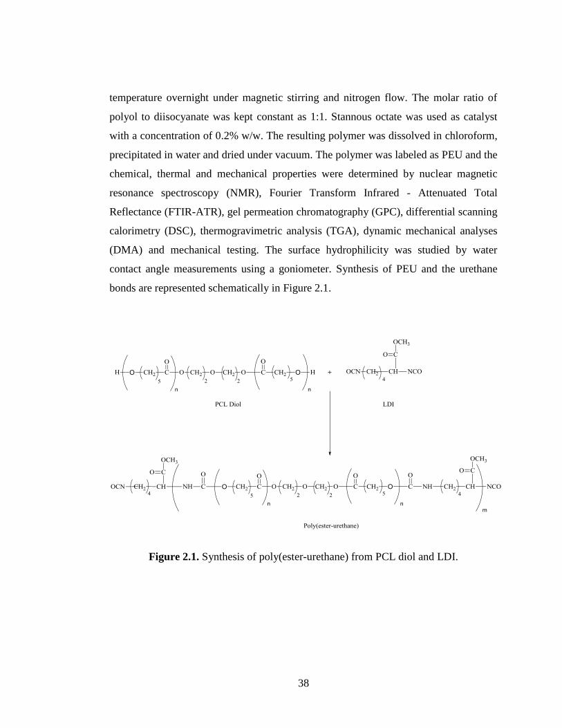
38
temperature overnight under magnetic stirring and nitrogen flow. The molar ratio of
polyol to diisocyanate was kept constant as 1:1. Stannous octate was used as catalyst
with a concentration of 0.2% w/w. The resulting polymer was dissolved in chloroform,
precipitated in water and dried under vacuum. The polymer was labeled as PEU and the
chemical, thermal and mechanical properties were determined by nuclear magnetic
resonance spectroscopy (NMR), Fourier Transform Infrared - Attenuated Total
Reflectance (FTIR-ATR), gel permeation chromatography (GPC), differential scanning
calorimetry (DSC), thermogravimetric analysis (TGA), dynamic mechanical analyses
(DMA) and mechanical testing. The surface hydrophilicity was studied by water
contact angle measurements using a goniometer. Synthesis of PEU and the urethane
bonds are represented schematically in Figure 2.1.
Figure 2.1. Synthesis of poly(ester-urethane) from PCL diol and LDI.
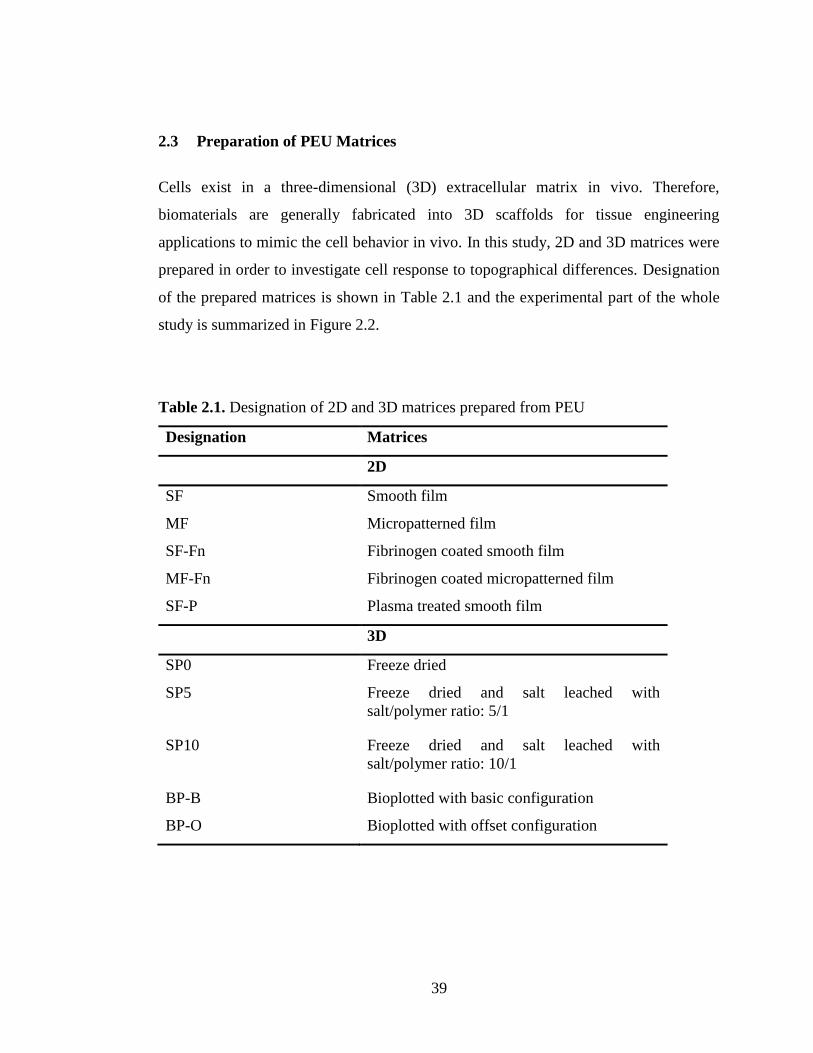
39
2.3 Preparation of PEU Matrices
Cells exist in a three-dimensional (3D) extracellular matrix in vivo. Therefore,
biomaterials are generally fabricated into 3D scaffolds for tissue engineering
applications to mimic the cell behavior in vivo. In this study, 2D and 3D matrices were
prepared in order to investigate cell response to topographical differences. Designation
of the prepared matrices is shown in Table 2.1 and the experimental part of the whole
study is summarized in Figure 2.2.
Table 2.1. Designation of 2D and 3D matrices prepared from PEU
Designation Matrices
2D
SF Smooth film
MF Micropatterned film
SF-Fn Fibrinogen coated smooth film
MF-Fn Fibrinogen coated micropatterned film
SF-P Plasma treated smooth film
3D
SP0 Freeze dried
SP5 Freeze dried and salt leached with
salt/polymer ratio: 5/1
SP10 Freeze dried and salt leached with
salt/polymer ratio: 10/1
BP-B Bioplotted with basic configuration
BP-O Bioplotted with offset configuration

40
Figure 2.2. Summary of experimental study.
2.3.1 Preparation of PEU Films
Polymer films were obtained by solvent casting on glass petri dishes of a 15% w/v
solution of PEU in chloroform and by drying first at room temperature and then in a
vacuum oven for 48 h. The films were about 150 – 250 µm thick. Samples for
characterization were cut from films, unless otherwise stated. Films without surface
modification was referred as smooth film (SF).
Synthesis of PEU
Preparation of PEU matrices
2D 3D
(by solvent casting) (by freeze drying, salt leaching and
bio-plotting)
Characterization
Chemical
Physical
Thermal
Mechanical
In vitro studies
Isolation of BMSCs
Culture of BMSCs on 2D and 3D matrices

41
Micropatterned film were obtained with the same approach on micropatterned
polydimethylsiloxane (PDMS) templates (groove width: 4 μm, ridge width: 10 μm,
depth: 4 μm, wall angle: 90o) which themselves were obtained on micropatterned
silicon wafers (Figure 2.3). After solvent evaporation, the films were peeled off from
the templates. Film thickness ranged from 150 µm to 250 µm for both type of films. In
order to improve cell adhesion on the films, fibrinogen (Fn) was adsorbed on the films.
Briefly, 250 µL Fn solution (1mg/mL in PBS) was pipetted on ethanol-sterilized dry
films. After 10 min, excess Fn solution was removed by pipetting and allowed to dry at
ambient temperature in a laminar flow.
Figure 2.3. Schematic presentation of micropatterned polymeric film preparation.
2.3.2 Preparation of PEU Sponges
PEU solution (15%, w/v) was prepared in 1,4 dioxane and poured into glass petri
dishes, frozen at -20oC and then lyophilized in a freeze dryer (Labconco Freeze Dry,
Model 78680, Missouri, USA).
PDMS template
10 µm 10 µm
4 µm
PEU solution is added
MF
PEU film is peeled of
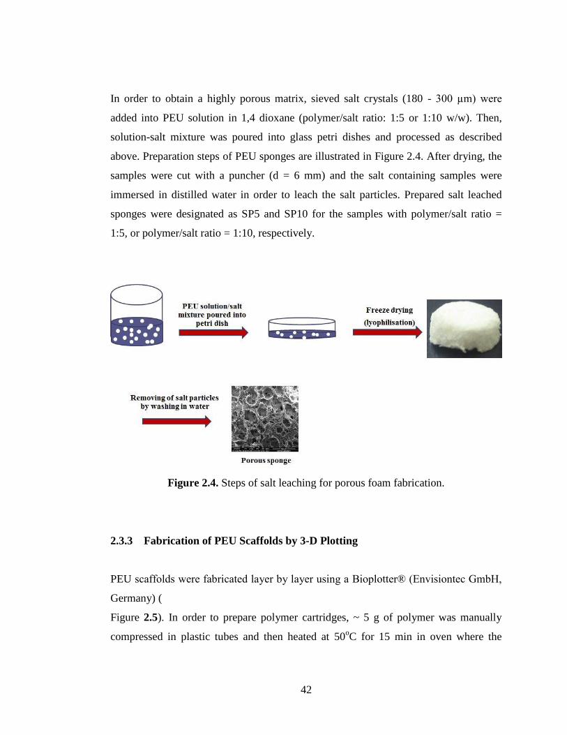
42
In order to obtain a highly porous matrix, sieved salt crystals (180 - 300 µm) were
added into PEU solution in 1,4 dioxane (polymer/salt ratio: 1:5 or 1:10 w/w). Then,
solution-salt mixture was poured into glass petri dishes and processed as described
above. Preparation steps of PEU sponges are illustrated in Figure 2.4. After drying, the
samples were cut with a puncher (d = 6 mm) and the salt containing samples were
immersed in distilled water in order to leach the salt particles. Prepared salt leached
sponges were designated as SP5 and SP10 for the samples with polymer/salt ratio =
1:5, or polymer/salt ratio = 1:10, respectively.
Figure 2.4. Steps of salt leaching for porous foam fabrication.
2.3.3 Fabrication of PEU Scaffolds by 3-D Plotting
PEU scaffolds were fabricated layer by layer using a Bioplotter® (Envisiontec GmbH,
Germany) (
Figure 2.5). In order to prepare polymer cartridges, ~ 5 g of polymer was manually
compressed in plastic tubes and then heated at 50oC for 15 min in oven where the
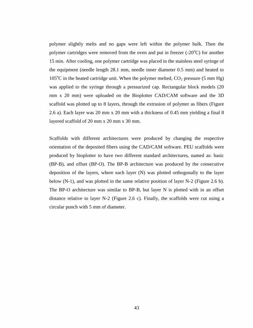
43
polymer slightly melts and no gaps were left within the polymer bulk. Then the
polymer cartridges were removed from the oven and put in freezer (-20oC) for another
15 min. After cooling, one polymer cartridge was placed in the stainless steel syringe of
the equipment (needle length 28.1 mm, needle inner diameter 0.5 mm) and heated to
105oC in the heated cartridge unit. When the polymer melted, CO2 pressure (5 mm Hg)
was applied to the syringe through a pressurized cap. Rectangular block models (20
mm x 20 mm) were uploaded on the Bioplotter CAD/CAM software and the 3D
scaffold was plotted up to 8 layers, through the extrusion of polymer as fibers (Figure
2.6 a). Each layer was 20 mm x 20 mm with a thickness of 0.45 mm yielding a final 8
layered scaffold of 20 mm x 20 mm x 30 mm.
Scaffolds with different architectures were produced by changing the respective
orientation of the deposited fibers using the CAD/CAM software. PEU scaffolds were
produced by bioplotter to have two different standard architectures, named as: basic
(BP-B), and offset (BP-O). The BP-B architecture was produced by the consecutive
deposition of the layers, where each layer (N) was plotted orthogonally to the layer
below (N-1), and was plotted in the same relative position of layer N-2 (Figure 2.6 b).
The BP-O architecture was similar to BP-B, but layer N is plotted with in an offset
distance relative to layer N-2 (Figure 2.6 c). Finally, the scaffolds were cut using a
circular punch with 5 mm of diameter.
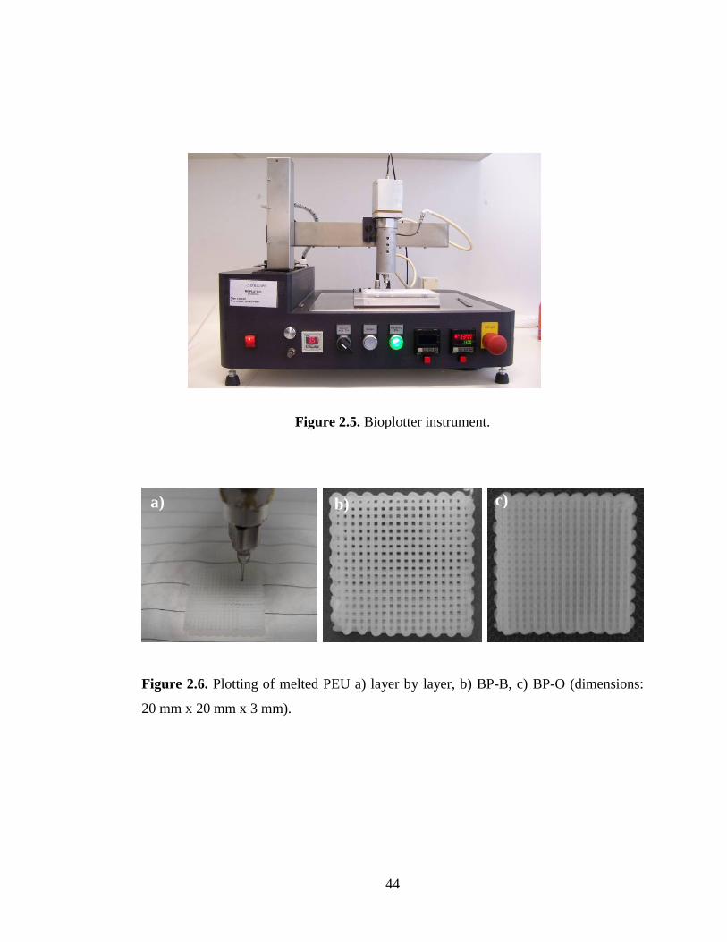
44
Figure 2.5. Bioplotter instrument.
Figure 2.6. Plotting of melted PEU a) layer by layer, b) BP-B, c) BP-O (dimensions:
20 mm x 20 mm x 3 mm).
a) b) c)
45
2.3.4 Modification of PEU Matrices with Oxygen Plasma
All 3D scaffolds were treated with oxygen plasma in order to enhance wettability of the
samples prior to cell culture tests. For this purpose, 3D scaffolds were placed in a
plasma chamber (Advanced Plasma Systems, with a SEREN IPS R 300 13.56 MHz
power supply, St. Petersburg, USA) and subjected to oxygen plasma (100 W) for 3
min. Samples were then sterilized and used in cell culture tests.
2.4 Characterization of Matrices
2.4.1 Composition and Molecular Weight
The chemical structure of the poly(ester-urethane) was determined by liquid state
NMR and ATR-FTIR study. 13
C-NMR spectra were recorded in CCl4/CDCl3 (2/3, v/v)
solvent system on a Bruker Spectrospin Avance DPX 400 spectrometer. FTIR-ATR
analysis was performed by Perkin Elmer Spectrum BX-FTIR Spectrometer (USA). The
molecular weight of the polymer was determined by gel permeation chromatography
(GPC, Polymer Laboratories, UK) with PL-GPC 220 with tetrahydrofuran (THF) as the
carrier solvent. The Universal Calibration method was used during the GPC analysis.
2.4.2 Thermal Characterization
The thermal properties of the polymer were determined by differential scanning
calorimetry (DSC) and thermogravimetric analysis (TGA). DSC was used to determine
the glass-transition temperature (Tg) and crystalline melting temperatures (Tm) under
nitrogen atmosphere by using DuPont 2000 Differential Scanning Calorimeter at a rate
of 10°C/min in the temperature range between -100°C and 100°C. Thermal stability
and thermal decomposition were studied by thermogravimetry using a Perkin Elmer
Pyris 1 TGA instrument (USA) under N2 atmosphere.

46
2.4.3 Determination of Porosity and Pore Size Distribution of PEU Matrices
Scaffold porosity was determined using liquid displacement method by pycnometer.
The pycnometer is a glass vessel with a close-fitting ground glass stopper with a
capillary hole through it. First, the sample and the empty pycnometer with glass stopper
was weighted and recorded as ms and mp, respectively. Second, the pycnometer was
filled with decane (nonsolvent for the samples), weighted and recorded as m1. Then, the
sample was immersed and the total weight (pycnometer + n-decane + sample) was
recorded as m2. Mass of decane (md) was found by subtracting (ms + mp) from m2.
Volume of n-decane that fills an empty pycnometer was calculated as follow:
d
pS mmV1
Where, d is density of n-decane. 1V gives the volume of the pycnometer.
Volume of n-decane that added (Vd) was obtained by dividing its mass (md) by its
density (726.28 kg/m3) and the volume of the sample ( sV ) was found as;
ds VVV 1
The percent porosity (P) of each scaffold was determined according to the following
equation:
P (%) 100a
sa
V
VV
Where aV is apparent volume of the sample calculated from simple formula for
cylinders: aV πr2h

47
Each step was repeated two times for each individual scaffold.
Pore size distributions of the freeze dried and salt leached scaffolds were determined by
Mercury intrusion Porosimeter (Quartachrome Corporation, Poremaster 60, Florida,
USA).
Porosity of bioplotted scaffolds were assessed by using micro-computed tomography
(µCT) (m-CT 20, SCANCO Medicals, Switzerland). Scanner settings were 40 keV and
248 mA. Entire scaffolds were scanned in around 200 slices. CT Analyser and
CTVolRealistic 3D Visualization (SkyScan, Belgium) softwares were used for image
processing in CT reconstructions, and to create and visualize the 3D representations.
2.4.4 Mechanical Properties of PEU Matrices
The mechanical properties of PEU matrices were studied by using Lloyd LRX 5K
Mechanical Tester, controlled by a computer running program (WindapR). For tensile
testing, the PEU samples were cut from prepared films as sheets (thickness = 0.20±0.07
mm, width = 10.0 mm, length = 40.0 mm) and attached to the holders of the instrument
with a free length of 10 mm. A constant extension rate of 10 mm/min was applied to all
samples.
For compression tests, 3D scaffolds in cylindrical shape were placed between
compression presses. The compressive speed was arranged as 2 mm/min. The
compressive modulus was evaluated from the initial linear elastic region of the stress –
strain curve.
The load deformation curve was printed for each specimen. The tensile and
compressive strengths were obtained from equation ρ = F/A, where ρ is the tensile or
compressive strength (MPa), F is the maximum load applied (N) before rapture, and A
is the initial area (m2) of the specimen. The load deformation curve was converted to

48
stress–strain curve, where stress is the load applied per unit area (F/A) and strain is the
deformation per unit length. Slope of straight line (elastic region of the stress-strain
curve) is accepted as the Young’s modulus of the specimen. Average of five
experiment values was taken.
2.4.5 Dynamical Mechanical Analysis (DMA) of PEU Films
Dynamic mechanical analysis (DMA) was carried to determine the viscoelastic
relaxation transition temperature of the PEU films with sample thickness around 200
µm. The measurements were carried out using a Perkin Elmer Pyris Diamond DMA
(USA). The samples were measured over a temperature range from -103°C to 29°C at a
heating rate of 3 C.min-1
under nitrogen atmosphere. The oscillation frequencies of 1
Hz, 2 Hz, 4 Hz, 10 Hz and 20 Hz were used and the analyses were carried out with
oscillatory tension mode. The storage modulus (E′), and tan delta (tan ) values were
recorded against temperature at different frequencies. The Tg values were obtained
from the peak maxima of tan delta curves.
2.4.6 Evaluation of In Situ Degradation
The stability of the polymer was evaluated by incubating in aqueous media with and
without the presence of Pseudomonas lipase enzyme. Degradation experiments were
carried out according to ASTM F-1635 standard of U.S.A. For enzymatic degradation,
various types of polymer matrices (film, freeze dried, salt leached and bioplotted) were
placed into vials containing 5 mL of PBS (0.1M, pH 7.4) with 0.18 U/mL enzyme and
0.02% of sodium azide to inhibit bacterial growth and incubated at 37oC within a water
bath shaker. The solutions were changed everyday. Samples were removed
periodically, washed with distilled water, freeze dried and weighed in order to examine
the weight loss due to erosion of the samples. The weighed samples were then placed
back into the fresh PBS medium containing enzyme and sodium azide. Same steps

49
were followed for hydrolytic degradation, except enzyme was not added into PBS
solution. Three parallel experiments were carried out for samples of each type of
specimen and the measured values were averaged. Percentage weight loss was
calculated as follows:
Weight loss (%) = [(W0 – W1)/W0] x 100
Where W0 and W1 are weight of dry samples before and after hydrolytic or enzymatic
degradation test, respectively.
2.4.7 Water Contact Angle Measurements
For contact angle measurements, thin films of PEU were obtained on glass slides by
solvent casting of the polymer solution (15% in chloroform). The water contact angle
values of films were measured by goniometer (KSV-CAM200, Finland) by using 5 µL
deionized water drops with average of five measurements. Contact angle measurements
were conducted on unmodified smooth PEU film surfaces (SF), on fibrinogen coated
surfaces (detailed below) and oxygen plasma treated surfaces.
2.5 In Vitro Studies
2.5.1 Isolation and Culture of Mesenchymal Osteoprogenitor Cells
The biocompatability of the polymer for the cells was tested by using rat bone marrow
mesenchymal stem cells (BMSCs). BMSCs were obtained from the femurs and tibias
of 6 week old, male Sprague Dawley rats and cultured as it was previously described
[128]. Briefly, femurs and tibias were aseptically excised, cleaned of soft tissue and
washed with Dulbecco's modified Eagle's medium (DMEM) with penicillin and
streptomycin about 10 times more of normal concentration. Then, the marrow within

50
the midshaft was flushed out with DMEM containing 20% fetal calf serum (FCS) and
100 U/mL penicillin and 100 µg/mL streptomycin, centrifuged at 3000 rpm for 5 min,
the resulting cell pellet was resuspended in medium and plated in T-75 flasks. These
primary cultures were allowed to reach approximately 80% confluence ( 15 days,
passage 0). Then the cells were trypsinized and stored frozen in liquid nitrogen until
use.
2.5.2 Cell Seeding and Culturing on PEU Matrices
Unpatterned and micropatterned 2D PEU films were cut into 1 cm x 1 cm square
shapes and placed in 24-well plates. The samples were sterilized in 70% ethanol for 2
h, and then washed with phosphate buffer saline (PBS, pH 7.4) three times and left to
dry under laminar flow. Cell supsension (30 μL) containing 1x10⁴ cells were seeded on
each film and incubated for 2 h at 37oC to allow cell attachment. Then osteogenic
media consisted of DMEM supplemented with 10% FCS, 10 mM β-glycerophosphate,
50 μg/mL L-ascorbic acid and 10 nM dexamethasone in the presence of 100 U/mL
penicillin and 100 μg/mL streptomycin was added. The cells on the films were then
allowed to grown for 3 weeks at 37oC in a humidified atmosphere containing 5% of
CO2 with changing the media every other day.
In cell culturing of 3D scaffolds; first salt leached and bioplotted 3D scaffolds were
sterilized under UV for 30 min for each surface. Then 100 μL of cell supsension
containing 5x10⁴ cells were seeded on each scaffold and the same culture conditions
were followed as described above.

51
2.5.3 Microscopy and Image Analysis
2.5.3.1 Scanning Electron Microscopy
The microstructures of the 2D and 3D PEU matrices were characterized using Scanning
Electron Microscope (SEM, FEI Quanta 400F, Holland). The samples were mounted
on aluminum stubs, sputter-coated with gold–palladium (AuPd) under an argon
atmosphere. For examination of cell morphology and deposited minerals, cell seeded
samples were fixed with 2.5% glutaraldehyde in 0.14M sodium cacodylate buffer (pH
7.4) for 2 h at room temperature, rinsed in cacodylate buffer, and freeze dried.
2.5.3.2 Fluorescent Microscopy
The cell morphology and spreading at different time points were characterized by
fluorescent microscope (Leica, TCS SPE, Germany). For fluorescent examination, the
samples were washed twice with PBS (10 mM, pH 7.4) fixed in 4% paraformaldehyde
solution in PBS for 15 min at room temperature, and treated with triton X-100 (1%) for
5 min to permeabilize the cell membrane. Samples were then incubated at 37oC for 30
min in 1% bovine serum albumin (BSA)-PBS (10mM pH 7.4) solution and incubated
with FITC-labeled phalloidin and DAPI to stain F-actins and the nuclei, respectively.
2.5.4 Cell Proliferation
Number of viable cells on the samples was assessed with Alamar Blue assay (US
Biological) at different time points. Prior the measurement, the culture medium in the
wells was discarded and the wells were washed with sterile PBS to remove any
remaining medium. Then Alamar Blue solution (10%, 1 mL) in colorless DMEM was
added to the wells and incubated at 37°C and 5% CO2 for 1 h. After 1 h, 200 µL of the
test solution was transferred to a 96 well plate and absorbance was determined at 570

52
nm and 595 nm using the plate reader (Molecular Devices, V max Microplate Reader,
USA). The test medium in the wells was then discarded, washed with sterile PBS, fresh
complete medium was added to the wells and the incubation was continued.
2.5.5 Determination of Osteoblastic Differentiation
2.5.5.1 Alkaline Phosphatase (ALP) Activity
ALP activity was determined on BMSC seeded 2D films by using a biochemical
Randox kit (USA), based on conversion of p-nitrophenyl phosphate to p-nitrophenol.
The absorbance of p-nitrophenol formed was spectrophotometrically measured at 405
nm and amount of enzyme was calculated from a calibration curve according to
manufacturer’s description. The analysis carried out with triplet samples.
2.5.5.2 Matrix Mineralization
Mineralization by osteoblasts on 2D film matrices was studied by labeling the calcium
phosphate formed with tetracycline as described earlier [139]. The cells seeded on the
TCP and films were cultured for 3 weeks. On the third day of culture the previously
used antibiotics (penicillin and streptomycin) were replaced with tetracycline (10
mg/mL). At the end of third week, the cells were washed with PBS, then with 70%
ethanol and fixed in 96% ethanol at 4oC for 6 h. Ethanol was discarded and the films
were left to dry in the dark. Mineralization was studied at an excitation wavelength of
480 nm using the fluorescence microscope (Leica, TCS SPE, Germany).
On the other hand, mineralization on 3D scaffolds was examined by von Kossa staining
and SEM/EDX analysis after 5 weeks of culture. For von Kossa staining, seeded
scaffolds were fixed with PFA as described before, washed with distilled water and
incubated in 5% AgNO3 under ultraviolet light for 30 min. After rinsing in several

53
changes of distilled water, samples were treated with 5% sodium thiosulphate for 5 min
in order to remove unreacted silver. Then samples were rinsed in distilled water for
several times before visualization under light microscopy. For SEM/EDX analysis,
samples were prepared as described in section 2.5.3.1.

54
CHAPTER 3
3. RESULTS AND DISCUSSION
3.1 Characterization of PEU Matrices
In this study; a biodegradable poly(ester-urethane) (PEU) was synthesized from
polycaprolactondiol (PCL) and lysinediisocyanate (LDI). The polymerization and the
chemistry of the PEU were examined with FTIR-ATR, GPC and NMR and the results
provided a confirmation of the successful synthesis.
3.2 Liquid State NMR, FTIR-ATR, GPC and Contact Angle Analyses
The chemical structure of the synthesized PEU polymer was verified using its 13
C-
NMR and FTIR-ATR spectra. In 13
C-NMR spectrum it was seen that –OH bonded
specific peaks of alkyl carbons (32 ppm ve 68 ppm) present in PCL, were not present in
the PEU spectrum and a new urethane carbonyl carbon peak demonstrating the
formation of PEUs appeared (157 ppm) (Figure 3.1).

55
Figure 3.1. 13
C NMR spectrum of PEU and PCL diol.
FTIR is useful in the characterization of the functional groups present in the polymer.
The IR spectra of PEU and one of its precursors, PCL are shown in Figure 3.2. In the
PEU spectrum, N-H stretching and bending vibration of urethane bonds at 3362 cm-1
and 1524 cm-1
were observed. Besides, disappearance of hydroxyl peak of PCL (3500
cm-1
) and the NCO peak in LDI (2260 cm-1
) [83] are indications of successful synthesis
of PEU. In addition, GPC data of PEU show that weight average and number average
molecular weights were 58.3x10³ and 19.5x10
3, respectively (Table 3.1).
Surface wettability of a biomaterial is very important in the sense of protein - surface
interaction which eventually determines cell attachment. Contact angle is dependent on
polymer surface hydrophilicity which influence cell adhesion. As seen in Table 3.1,
water contact angle of the smooth PEU films decreased from 90±3 to 82±1 as a result
of Fn coating. Fn adsorption led to a slight increase in hydrophilicity of smooth PEU

56
films which may enhanced the interaction between cells and biomaterial. There are also
contrary results reported in the literature. Bumgardner et al. (2003) evaluated the
contact angle, protein adsorption and osteoblast attachment to intact and chitosan
coated titanium surfaces and they reported that protein adsorption was higher on
chitosan coated titanium surfaces even chitosan coatings exhibited higher water contact
angles (76 ) than uncoated titanium controls (32 ). They concluded that high amine
positive charge of the chitosan promoted greater protein adsorption and enhanced cell
attachment [154]. Thus, we can hypothesize that lysine based polymer (PEU) used in
this study may enhance cell adhesion by promoting fibrinogen adsorption to the
polymer surface.
On the other hand, a significant decrease from 90±3 to 23±1 was observed for
oxygen plasma applied film surfaces (SF-P), which indicates considerable increase of
surface wettability (Table 3.1). Oxygen plasma application is widely used in tissue
engineering applications to enhance initial cell attachment onto hydrophobic synthetic
polymers [155].
Table 3.1. The molecular weight, heterogeneity index (HI) and water contact angle
values of SF
Molecular weight HI Water contact angle ( )
Mw
(g.mol-1
) x103
Mn
(g.mol-1
) x103
SF SF-Fn SF-P
58.3 19.5 2.98 90 ± 3 82 ± 1 23 ± 1

57
Figure 3.2. FTIR-ATR spectra of PEU and PCL diol.
3.3 Thermal Properties of PEU Matrices
In biomedical applications it is important to know thermal properties of the polymers,
because they determine the physical properties of the materials. If the glass transition
temperature (Tg) of the polymer is above that of body temperature, the polymer is rigid
when implanted. On the other hand, if the Tg value is below the body temperature, as in
the PEU synthesized in this study, it indicates the elastomeric characteristic of the
polymer.
The thermal properties of the prepared PEU matrices were determined by DSC and
TGA. Thermal data for processed samples are reported in Table 3.2. For DSC analysis,
four samples representing different preparation methods were examined. The first-
heating DSC thermograms for different specimens, namely smooth film (SF), freeze

58
dried sample (SP0), salt leached sample (SP10) and bioplotted basic (BP-B) samples
are presented in Figure 3.3. The melting peaks (Tm) were observed at about 45oC, 41
oC,
40oC and 51
oC for SF, SP0, SP10 and BP-B, respectively. The thermogram of BP-B
has relatively broader melting peak which is attributed to broader distribution of crystal
sizes than other specimens [156]. The smaller peak near 39oC is due to melting of small
and imperfect crystallites formed during the solvent evaporation. This low melting
point make the polymer a good candidate for processing by melting techniques;
however a Tm of ~45°C make the polymer unsuitable for thermal sterilization which
may be an important criterion in biomedical applications.
Although the melting thermograms differ from each other, all specimens showed close
Tg values ranging from -45oC to -43
oC. The differences in melting thermograms can be
attributed to different preparation of the mentioned four specimens: The films were
casted by chloroform evaporation, salt leached samples were prepared in different
solvent (dioxane) and bioplotted samples were obtained by melting process. Therefore,
each specimen showed different thermal responses.
The thermogravimetric analysis (TGA) was carried out for 2D SF samples and 3D
SP10 and BP-B scaffolds in order to assess the thermal stability of the synthesized
polymer and to define the effect of salt leaching and melt processing on thermal
properties (Figure 3.4). The TGA analysis shows that the polymer is thermally stable as
the degradation temperature for SF, SP10 and BP-B samples was around 300°C. It is
seen that neither salt leaching process nor melting process for rapid prototyping did not
cause a significant change in the degradation temperature of the polymer since TGA
curves of SP10 and BP-B displayed similar weight loss phenomena as solvent casted
film samples.

59
Table 3.2. Thermal data for different PEU matrices
Sample Tg (oC) Tm (
oC) Td (
oC)
SF -45.29 45.27 300
SP0 -42.70 40.66 -
SP10 -44.41 40.28 300
BP-B -45.34 51.37 300
Figure 3.3. DSC thermograms of PEU matrices.
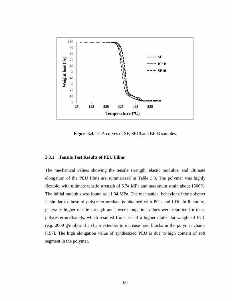
60
Figure 3.4. TGA curves of SF, SP10 and BP-B samples.
3.3.1 Tensile Test Results of PEU Films
The mechanical values showing the tensile strength, elastic modulus, and ultimate
elongation of the PEU films are summarized in Table 3.3. The polymer was highly
flexible, with ultimate tensile strength of 5.74 MPa and maximum strain about 1500%.
The initial modulus was found as 11.94 MPa. The mechanical behavior of the polymer
is similar to those of poly(ester-urethane)s obtained with PCL and LDI. In literature,
generally higher tensile strength and lower elongation values were reported for these
poly(ester-urethane)s, which resulted from use of a higher molecular weight of PCL
(e.g. 2000 g/mol) and a chain extender to increase hard blocks in the polymer chains
[157]. The high elongation value of synthesized PEU is due to high content of soft
segment in the polymer.
0
10
20
30
40
50
60
70
80
90
100
25 125 225 325 425 525
Wei
gh
t lo
ss (
%)
Temperature (oC)
SF
BP-B
SP10

61
Figure 3.5 shows stress –strain behavior of the prepared PEU film which is typical for
viscoelastic poly(ester-urethane)s, and indicates the semi-crystalline structure of the
prepared films [83,157]. As it is seen in the stress–strain curve, after a steep stress,
there is a yield point where formation of a neck was visually observed. The stress
increased sharply almost up to a certain small strain and then increased linearly with an
incredible increase in the strain.
Table 3.3. Tensile test parameters of PEU
Mechanical Properties
Ultimate Tensile
Strength, (MPa)
Modulus of Elasticity
(E´), (MPa)
Elongation at Break
(%)
5.74 ± 1.33 11.94 ± 1.03 1504 ± 291
Figure 3.5. Representative stress–strain curve of the PEU synthesized in this study.
0
2
4
6
8
10
0 200 400 600 800 1000 1200 1400
Str
ess
(MP
a)
Strain (%)

62
3.3.2 Dynamical Mechanical Analysis (DMA) of PEU Films
DMA analysis was carried out in order to determine the relationship between tan δ, and
storage modulus (E´). DMA measures the modulus (stiffness) and energy dissipation
properties of a material as the material is deformed under a periodic stress. It is
particularly useful for evaluating polymeric materials that exhibit time, frequency and
temperature effects on mechanical properties due to their viscoelastic nature.
DMA plots for tan delta (Figure 3.6) and storage modulus (E´) (Figure 3.7) of PEU
films at different frequencies (1, 2, 4, 10 and 20 Hz) were obtained as a function of
temperature. The mechanical behaviors of thermoplastic polyurethanes are known to be
dependent on strain rate. Storage modulus is a measure of material stiffness and can be
used to provide information about molecular weight, degree of cure and cross-link
density of the polymer. The storage modulus is plotted logarithmically in order to
clarify the transition regions. As seen in Figure 3.7, the storage modulus rapidly
decreases above 20 C which confirms the DSC results that the synthesized polymer
would be useful in low-temperature applications.
In addition to DSC analysis, DMA gave a further insight into the transition temperature
(Tg). The temperature corresponding to the maximum peak of tan δ is defined as the
glass transition temperature. Tan δ peaks and corresponding Tg values are given in
Table 3.4. The tan δ curve displays a broad peak between -60 C and 10 C which is
associated with the glass transition region of the PCL soft block of the PEU. The Tg
region of the LDI hard block segment of the polymer was not obvious which is evident
for relatively low amount of hard blocks in the polymer. Hassan et al. (2006) observed
the Tg region of the hard block segment between 25 - 34 C for low amount and
between 10 - 45 C for high amount of chain extender in LDI/PCL based poly(ester-
urethane)s [157]. They also observed that the hard block Tg was more prominent for

63
the polymer with relatively high amount of chain extender. The Tg value observed at 1
Hz (-43.86 C) showed good correlation with the Tg value obtained by DSC (-45.29 C).
As seen in Figure 3.8, Tg has shifted with strain rate (frequency). Shifting in Tg was
not observed at all frequencies, but when increasing the frequency from 2 to 4 Hz and
from 10 to 20 Hz (Table 3.4). Yi et al. (2006) defined this shifting as a shift in apparent
Tg, which is mechanically recognized Tg by the material at a given strain rate [158].
This increase in Tg is consistent with elastomeric polymers which indicates formation
of phase mixing at some degree [159].
Table 3.4. Tan δ peak magnitude and Tg values for PEU at different frequencies
Hz Tg (°C) Tan δ
1 - 43.86 0.23
2 - 43.86 0.23
4 - 39.88 0.26
10 - 39.88 0.29
20 - 34.56 0.37

64
Figure 3.6. Tan δ versus temperature curve of PEU film at different frequencies.
Figure 3.7. Temperature dependency of the storage modulus for PEU film at different
frequencies.

65
Figure 3.8. Shifting of Tg at different frequencies.
3.4 Morphology of 3D PEU Matrices
Morphology and pore interconnection of porous structures of the 3D scaffolds were
observed by SEM. The synthesized PEU fabricated into scaffolds of any desired shapes
with different pore sizes, either by freeze drying or by salt leaching or by bioplotting,
as shown in Figure 3.9 and Figure 3.10. The bioplotted scaffolds as basic (BP-B) or as
offset (BP-O) configuration had fully interconnected pore architectures with a strand
diameter and strand distance and pore size of ~450 μm. The approximate pore sizes of
SP0, SL5 and SL10 were in the range of 5 - 50 μm, 10 - 300 μm and 30 - 350 μm,
respectively. The surface area/volume ratio of the salt leached (SP5 and SP10) sponges
was greatly increased compared to SP0 sponges obtained by freeze drying. Higher
surface area/volume ratio provide more area for the cells to attach, thus would increase
the percentage of total cells attached and cell diffusion into the scaffold. SEM images
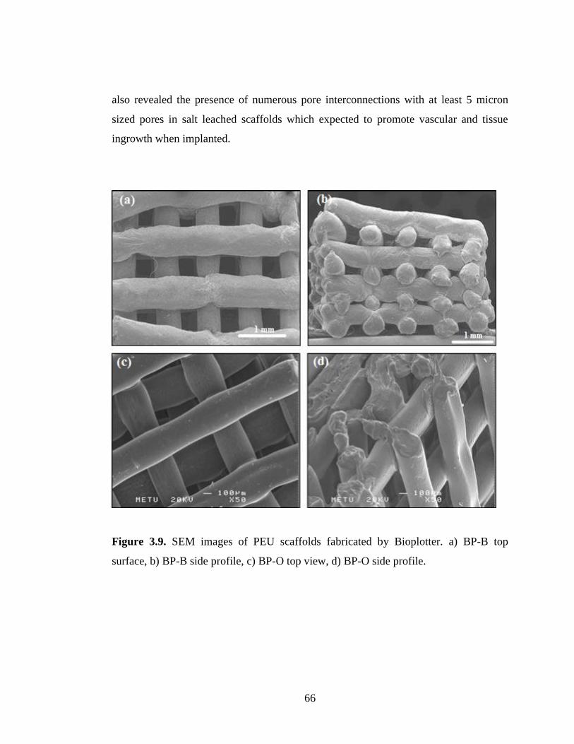
66
also revealed the presence of numerous pore interconnections with at least 5 micron
sized pores in salt leached scaffolds which expected to promote vascular and tissue
ingrowth when implanted.
Figure 3.9. SEM images of PEU scaffolds fabricated by Bioplotter. a) BP-B top
surface, b) BP-B side profile, c) BP-O top view, d) BP-O side profile.
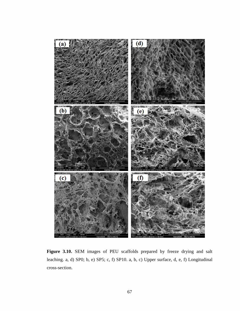
67
Figure 3.10. SEM images of PEU scaffolds prepared by freeze drying and salt
leaching. a, d) SP0; b, e) SP5; c, f) SP10. a, b, c) Upper surface, d, e, f) Longitudinal
cross-section.

68
3.5 Porosity and Pore Size Distribution of 3D PEU Matrices
3.5.1 Determination of Porosity
The microstructures of the scaffolds are defined by their porosity values [160]. Pore
size and porosity are among the most important parameters used to characterize a
scaffold. Porosity refers to the overall percentage of void space within a solid, whereas
pore size indicates the diameter of individual voids in the scaffold. It is a general
acceptance porosity, mean size, pore size distribution and pore interconnectivity play a
critical role in scaffold design and production because of its importance for cell
migration, proliferation and ECM formation [161]. Permeability of a scaffold is also
important for nutrition diffusion and waste clearance. Some researchers reported the
pore size as determinant for sufficient tissue ingrowth where a minimum pore size for
tissue ingrowth and vascularization was indicated as 100 µm [162], while some others’
studies suggested that the controlling factor is the pore interconnection size which is
related to both pore size and the extent of porosity. A minimum pore diameter is
important that as cells proliferate the pore diameter will eventually drop to a size where
cells can not longer fit into the pores which will lead to decrease in cell viability. For
bone tissue engineering, the ability of a scaffold to enhance osteogenic differentiation
and support new bone formation is dependent pretty much on the pore size and porosity
of the scaffold. The importance of scaffold porosity and pore size can be attributed to
the native structure of bone, which itself is a porous tissue. Cortical bone is mainly a
dense structure, but its small porous region (totally 10%) allows vascularization and
cellular infiltration. On contrary, cancellous bone has a highly porous structure (50-
90%) [163].
In an in vivo study, ceramics with a pore size range of 50 - 100 µm and 200 - 400 µm
with similar porosity (60%) were compared. It has been shown that tissue ingrowth was
totally achieved by specimen with small pores, whereas in larger pored specimen tissue

69
did not infiltrated all the pores after a couple of months. The results suggests that a
well-interconnected 50 - 100 µm pores could be more suitable for rapid and sustained
bone ingrowth when compared with less connected but larger pores of 200 - 400 µm
with similar porosity [164].
Thus, achieving structural interconnectivity between pores is crucial in scaffold
fabrication. Klawitter et al. (1971) conducted several studies about porous ceramics as
bone graft substitutes. In one study, they showed that interconnection sizes at least 100
µm, 40 µm and 5 µm were required for the ingrowth of mineralized tissue, osteoid and
fibrous tissue, respectively [165]. Lu et al. (1999) reported 50 µm as the critical pore
interconnection size for bone ingrowth by using HAp or β-TCP in their study [166].
The minimum level for continuous bone integration was reported to be around 50-60%.
All these thresholds for pore size, pore connectivity and porosity volume is generally
attributed to nondegradable scaffolds as degradation leads to pore opening in the
structure. Therefore, optimal degree of connectivity and porosity for degradable
scaffolds may be lower than those established in literature for nondegradable ones
[161].
In this study, pore size and porosity of scaffolds produced by Bioplotter were
determined by using micro computed tomography (µ-CT), while porosity of sponges
were obtained by using pycnometer. For the prepared scaffolds mean pore sizes are
obtained from SEM images, while pore size distribution is determined by mercury
porosimeter. Although SEM is useful for evaluation of pore shape and size, SEM
image analysis does not give exact size distribution of the pores. In the last decade, a
computer aided technology, µ-CT, has been applied specially in bone engineering
studies for imaging fabricated scaffolds and constructs.
The percent porosity values of the bioplotted scaffolds were found as 65% and 56% for
BP-B and BP-O, respectively (Figure 3.11). It was observed that the pores were

70
interconnected throughout the whole structure with controlled pore size approximately
450 µm as it was also seen in SEM images. This is especially important when most
scaffolds produced by conventional methods do not have interconnectivity, and the
porosity decreases towards downwards. Percent porosity of freeze dried scaffolds was
found as 33% by using pycnometer. Salt particles used for producing high porosity
have increased the porosity up to 85% and 96% depending on the amount of salt
particles used. The porosity profiles of all 3D scaffolds are tabulated in Table 3.5.
Table 3. 5. Porosity of 3D scaffolds
Sample Porosity (%)
SP0 33
SP5 85
SP10 96
BP-B 65
BP-O 56
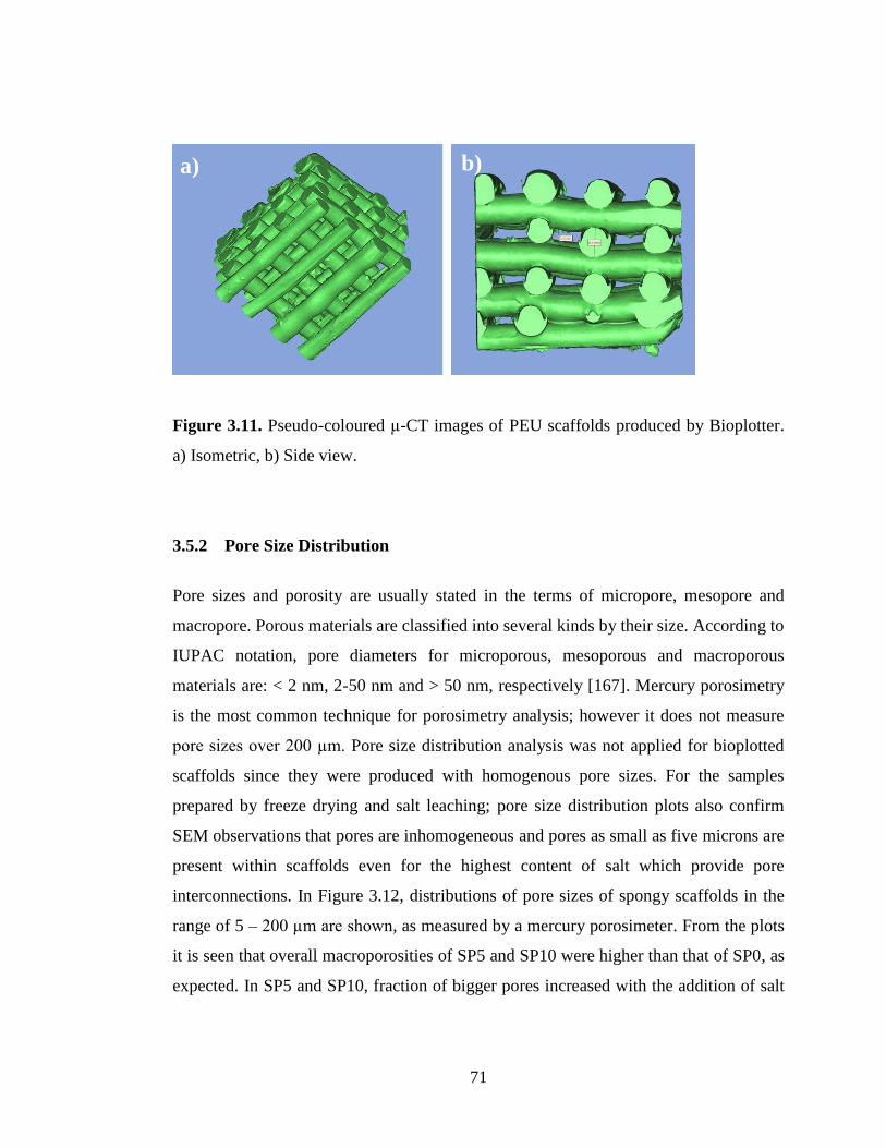
71
Figure 3.11. Pseudo-coloured µ-CT images of PEU scaffolds produced by Bioplotter.
a) Isometric, b) Side view.
3.5.2 Pore Size Distribution
Pore sizes and porosity are usually stated in the terms of micropore, mesopore and
macropore. Porous materials are classified into several kinds by their size. According to
IUPAC notation, pore diameters for microporous, mesoporous and macroporous
materials are: < 2 nm, 2-50 nm and > 50 nm, respectively [167]. Mercury porosimetry
is the most common technique for porosimetry analysis; however it does not measure
pore sizes over 200 µm. Pore size distribution analysis was not applied for bioplotted
scaffolds since they were produced with homogenous pore sizes. For the samples
prepared by freeze drying and salt leaching; pore size distribution plots also confirm
SEM observations that pores are inhomogeneous and pores as small as five microns are
present within scaffolds even for the highest content of salt which provide pore
interconnections. In Figure 3.12, distributions of pore sizes of spongy scaffolds in the
range of 5 – 200 µm are shown, as measured by a mercury porosimeter. From the plots
it is seen that overall macroporosities of SP5 and SP10 were higher than that of SP0, as
expected. In SP5 and SP10, fraction of bigger pores increased with the addition of salt
b) a)
72
particles. For SP0, the fraction of pores over 20 µm is very low, while for SP5 and
SP10 the fraction of pores over 20 µm is high. Almost no pores with diameter over 50
µm were present in SP0. The volume fraction of pores between 20 - 300 µm was much
closer to each other in SP10 when compared to SP5, indicating existence of relatively
more homogenous pore distribution in SP10.

73
Figure 3.12. Pore size distributions of freeze dried spongy scaffolds. a) Freeze dried
(SP0), b) Low salt leaching (SP5), c) High salt leaching (SP10).
a)
b)
c)
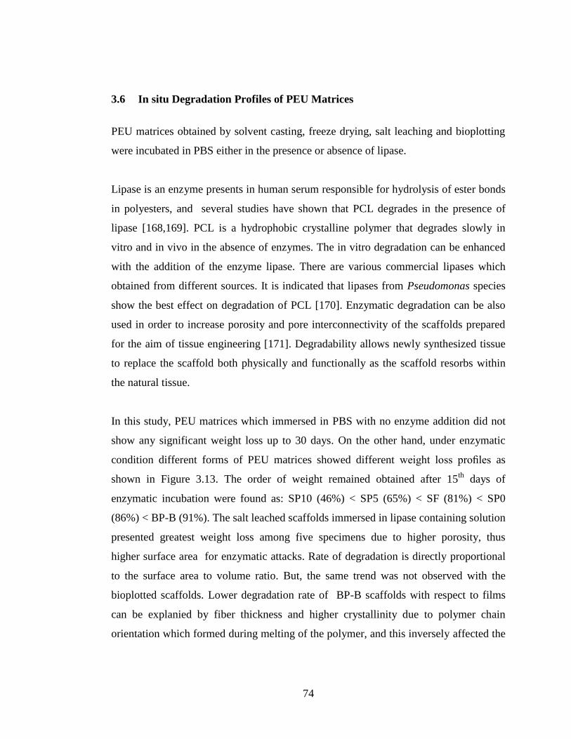
74
3.6 In situ Degradation Profiles of PEU Matrices
PEU matrices obtained by solvent casting, freeze drying, salt leaching and bioplotting
were incubated in PBS either in the presence or absence of lipase.
Lipase is an enzyme presents in human serum responsible for hydrolysis of ester bonds
in polyesters, and several studies have shown that PCL degrades in the presence of
lipase [168,169]. PCL is a hydrophobic crystalline polymer that degrades slowly in
vitro and in vivo in the absence of enzymes. The in vitro degradation can be enhanced
with the addition of the enzyme lipase. There are various commercial lipases which
obtained from different sources. It is indicated that lipases from Pseudomonas species
show the best effect on degradation of PCL [170]. Enzymatic degradation can be also
used in order to increase porosity and pore interconnectivity of the scaffolds prepared
for the aim of tissue engineering [171]. Degradability allows newly synthesized tissue
to replace the scaffold both physically and functionally as the scaffold resorbs within
the natural tissue.
In this study, PEU matrices which immersed in PBS with no enzyme addition did not
show any significant weight loss up to 30 days. On the other hand, under enzymatic
condition different forms of PEU matrices showed different weight loss profiles as
shown in Figure 3.13. The order of weight remained obtained after 15th
days of
enzymatic incubation were found as: SP10 (46%) < SP5 (65%) < SF (81%) < SP0
(86%) < BP-B (91%). The salt leached scaffolds immersed in lipase containing solution
presented greatest weight loss among five specimens due to higher porosity, thus
higher surface area for enzymatic attacks. Rate of degradation is directly proportional
to the surface area to volume ratio. But, the same trend was not observed with the
bioplotted scaffolds. Lower degradation rate of BP-B scaffolds with respect to films
can be explanied by fiber thickness and higher crystallinity due to polymer chain
orientation which formed during melting of the polymer, and this inversely affected the

75
degradation rate. The higher the crystallinity, the lower is the biodegradation rate. It has
been shown that degradation rate in the amorphous regions could be twenty times faster
than that of crystalline regions [156].
Controlling the degradation rates of synthetic polymer scaffolds is one of their
advantages over natural materials. Scaffolds produced from synthetic polymers such as
PCL could preserve their structure without showing any degradation when incubated in
PBS for months, due to their hydrophobicity [96]. Some studies have reported that the
biodegradation rate of PCL depends on the shape and inherent surface area: volume
ratio of the PCL matrix, with films being slowly degraded, whereas nano- and
microparticles are quickly degraded [172].
Figure 3.13. Degradation profiles of 2D films and 3D scaffolds in PBS with 0.18
U/mL of lipase (n=3).
0
10
20
30
40
50
60
70
80
90
100
0 5 10 15 20
Wei
gh
t re
main
ed (
%)
Time (days)
SF
SP0
SP5
SP10
BP-B

76
3.7 Compressive Modulus of 3D PEU Matrices
Tissue engineering scaffolds acts as a physical support structure as an analog for ECM
of natural tissues. Beside necessity for mechanical functionality within natural tissue,
adequate mechanical strength of a scaffold is required for facility during in vitro cell
culture and implantation applications [173]. Scaffold features, such as pore structure,
mechanical strength and degradation properties, play important roles in cellular growth
and function since specific cells need mechanical stimuli generated by the scaffold to
mediate cell stiffening due to cell focal adhesions attachment [174]. Thus, parameters
like, molecular weight, crystallinity, microstructure (porosity, mean pore size, pore
shape, interconnectivity and specific surface area) and preparation method that
influence scaffold stiffness would inherently influence the cell response. Different cells
show varying responses. For example, mesenchymal stem cells (MSCs), fibroblasts
and epithelial cells have been shown to exhibit better cell spreading, adhesion and
proliferation on stiffer scaffolds [118].
Compressive elastic modulus is a measure of material stiffness. In present study, the
effect of microstructure on the elastic modulus of the scaffolds which were obtained by
freeze drying, by salt leaching and by bio-plotting were evaluated by compressive tests.
Representative compressive stress-strain curves for sponges and bioplotted scaffolds
are shown in Figure 3.14 and Figure 3.15, respectively. Spongy scaffolds (SP0, SP5
and SP10) exhibited similar stress–strain behavior characteristic of low-density,
elastomeric open-cell foams as defined by Harley et al (2007) [173]. The compression
curve of these types of scaffolds is typically characterized by three distinct zone. The
first zone is a linear elastic regime (bending), the second is a collapse plateau regime
(pores start to collapse) and the third one is a densification regime (complete collapsing
of pores) (distinct zones are shown on curve of SP0 in Figure 3.14).

77
0,0 0,5 1,0 1,5 2,0 2,5 3,0 3,5 4,0 4,5 5,0
0
2
4
6
8
10
12
14
SP5
SP0
Load
(N
)
Deformation (mm)
SP10
Figure 3.14. Representative load- deformation curves of freeze dried and salt leached
scaffolds.
0,0 0,5 1,0
0
3
6
9
12
15
Lo
ad
(N
)
Deformation (mm)
BP-OBP-B
Figure 3.15. Representative load-deformation curve of bioplotted scaffolds
Densification
Plateu
Linear
elasticity

78
As seen in Table 3.6, bioplotted scaffolds (BP-B and BP-O) displayed significantly
higher compressive stiffness than the spongy scaffolds obtained by freeze dried (SPO)
and salt leached (SP5 and SP10) samples. Addition of leaching particles decreased the
compressive elastic modulus of SP0 from 584±67 kPa to 148±6 kPa for SP5 and to
38±2 kPa for SP10, under dry conditions. In the case of bioplotted scaffolds, it was
observed that alteration of fiber orientation from basic (BP-B) to offset (BP-O)
architecture leaded a decrease in compressive modulus from 4720±540 kPa to
3450±610 kPa due to juxtaposition of sequential fibers along the Z axis. Yilgor et al.
(2008) also showed that scaffolds with basic configuration exhibited higher mechanical
strength [128]. Mechanical properties can be attributed to differences in
microarchitecture and porosity. SP10 had the highest porosity with a value of 96%,
thus showed lowest mechanical strength. Although SP0 displayed the lowest porosity,
BP-B and BP-O had the highest elastic modulus. This can be explained by re-
orientation of PEU chains during melt processing to form more crystalline structure as
confirmed by DSC and degradation studies. Increase of crystalline amount leads to
increase in mechanical strength.
As a supportive matrix for cell culture, a scaffold must have appropriate mechanical
strength. Generally, the optimum value for mechanical strength is correlated with the
strength of target tissue, but a strength of at least 100 kPa is reported to be necessary
[175]. Compressive moduli for cancellous bone are given as 50 - 500 MPa depending
on anatomical location [54]. When compared to natural bone, it is seen that
compressive moduli of all prepared scaffolds including bioplotted ones were lower than
this reported range. On the other hand, prepared scaffolds seem to have potential
mechanical stiffness to support osteogenic differentiation. It has been indicated that
scaffold stiffness plays an important role to induce differentiation into osteogenic
lineage. Pek et al. (2010) showed that human MSCs differentiated into osteogenic
phenotypes on 2D substrates with elastic modulus higher than 34 kPa; below which
MSCs differentiated into neural or myogenic phenotypes [176]. They further confirmed

79
the effect of matrix stiffness on the differentiation of human MSCs in 3D scaffolds.
These findings showed that PEU based scaffolds are not useful for load bearing
applications, but can be used for bone defects which demand only low compressive
strength and for soft tissue applications.
Table 3.6. Compressive modulus values of 3D scaffolds
Sample E´ (kPa)
SP0 584 ± 66
SP5 147 ± 6
SP10 38 ± 2
BP-B 4720 ± 540
BP-O 3450 ± 610
3.8 In Vitro Studies
3.8.1 In Vitro Cell Culture on 2D PEU Films
3.8.1.1 Cell Morphology
The effect of surface chemistry and micro-patterned topography of the films on cell
morphology and cytoskeleton organization were studied by SEM and fluorescence
microscopy
In view of the fact that responses are cell type-dependent, cells are generally aligned in
the direction of the groove on the substrates, known as contact guidance. It is well
known that contact guidance by grooves/ridges structures induces many cell types to

80
align along the groove direction. In several studies it is indicated that the degree of cell
orientation was significantly affected by groove depth rather than groove width [164,
165]. Yucel et al. (2010) reported that groove depths greater than 2 µm promoted
alignment of neurites [62]. Jeon et al. (2010) found that a height threshold of nearly 1
µm influences fibroblast alignment on both parallel line and orthogonal mesh patterns
[179]. In several studies it has been demonstrated that cell shape alterations due to
surface topography may influence differentiation [180]. Cairns et al. (2010)
investigated the influence of surface topography on osteoblast adhesion, proliferation
and differentiaon in the presence an adsorbed fibronectin layer. They reported that
presence of fibronectin on the surface improve cell adhesion and early osteoblastic
differentiation [181].
In this study, SEM and fluorescence microscope images showed that the cells attached
very well with flattened morphology on both modified and unmodified PEU film
surfaces which indicate cell compatability of the synthesized polymer. Cells were
extended in the direction of grooves on both Fn-free (MF) and Fn- coated (MF-Fn)
surfaces, while cells were spreaded in a random fashion on smooth surface (SF and SF-
Fn) as seen in Figure 3.16 and Figure 3.17. Orientation angles of the cells were
calculated from the measured values of thirty representative cells. The orientation angle
was found to be within 10° of the groove direction which indicates very good
alignment of the cells. Cells with 45° orientation angle are considered as randomly
dispersed [105].

81
Figure 3.16. Fluorescence images of BMSCs seeded on a) MF-Fn, b) MF (mag. x10,
day 3). Actin microfilaments (green) were visualized by FITC-labeled phalloidin. Cell
nuclei were visualized by DAPI (blue).

82
Figure 3.17. SEM images of BMSCs seeded on a) SF, b) MF. c) and d) Closer views
of alignment within the groove (day 3).
3.8.1.2 Cell Proliferation
Proliferation of BMSCs on unpatterned and micro-patterned PEU films with or without
Fn coating was studied by Alamar blue assay after 21 days with TCPS serving as the
control (Figure 3.18). This study confirmed that the novel PEU polymer synthesized in
this study was not cytotoxic. On the contrary, the proliferation rates were very similar
to those on TCPS and this is quite a success. The initial attached cell numbers on Fn-
coated surfaces were significantly higher than on Fn-free surfaces. The initial attached

83
cell numbers on Fn-coated surfaces were significantly higher than on Fn-free
surfaces.This might partially be due to a slight increase in the hydrophilicity of PEU
film surfaces upon Fn adsorption which was was also indicated by Kenar et al. (2006)
[139]. Increase in cell population was higher on Fn coated surfaces regardless of the
presence of micro-patterns. Actually, presence of micro-patterns did not have
significant influence in terms of attachment or proliferation.
An increase was observed in the proliferation on each sample up to day 14, followed by
a decrease towards day 21. The decrease in proliferation was probably due to
confluency; after two weeks cells covered the whole film surfaces forming a cell sheet
which led to cell death or cell migration to the well plate. Moreover, a decreased
proliferation rate is expected, since during differentiation phase the bone marrow stem
cells induced to differentiate into osteocytes stop dividing and start to express
osteogenic markers.
There is not a certain hydrophilicity value for optimum cell-material interaction. Cell
type and matrix surface determine the cell adhesion strength. Ardhaoui et al. (2008)
investigated the effects of water contact angle on cell adhesion strength and cell
viability of various cell types on polystyrene surfaces having different contact angles.
They found that some cell types attached better on moderately hydrophilic surfaces
while others adhered better on more hydrophilic surfaces [183]. In our study; contact
angle values are found to be 90 and 82 for SF and SF-Fn samples, respectively; and
Fn coated samples demonstrated better cell attachment.

84
Figure 3.18. Cell proliferation of BMSCs on PEU films and tissue culture plate
(control) quantified using Alamar Blue assay on days 1, 7, 14 and 21 (n=3).
3.8.1.3 Osteoblastic Differentiation
The osteogenic differentiation capability of BMSCs was studied by determining
alkaline phosphatase (ALP) activity and calcium deposition which are correlated with
osteoblastic phenotype. Differentiation on different PEU surfaces was evaluated at the
end of three weeks an the results are consistent with proliferation results; there is a
significant difference between the Fn coated and uncoated samples in terms of ALP
activity regardless of the presence of fibrinogen (Figure 3.19).
Mineral salts, mostly calcium phosphates constitute the inorganic matrix of bone and
are responsible for the hardness and compressive strength of the bones. Deposition of
calcium salts is an indication of mineralization. In the present study, mineralization of
the ECM by the osteoblasts was studied by staining calcium salts with tetracycline
0
20
40
60
80
100
120
140
160
180
TCPS SF SF-Fn MF MF-Fn
Cel
l n
um
ber
(x10
3)
Day 1
Day 7
Day 14
Day 21

85
(Figure 3.20). It was observed that mineralization is denser on Fn coated film surfaces.
Calcium minerals formed on all smooth and patterned films while for patterned films
mineralization was observed within the grooves as well as on the ridges. As it was
mentioned in cell proliferation study, presence of patterns on film surface showed no
difference in cell proliferation and bone differentiation compared to control smooth
surfaces; but alignment of cells along the grooves was observed.
Figure 3.19. ALP activity of BMSCs for the film samples at the end of three weeks
(n=3).
0
1
2
3
4
5
6
7
SF MF SF-Fn MF-Fn
AL
P A
ctiv
ity
(nm
ole
s/m
in/c
ell)

86
Figure 3.20. Fluorescence microscopy images showing mineralization achieved by
osteoblasts on polymeric films at the end of three weeks. a) SF, b) SF-Fn, c) MF, d)
MF-Fn (mag. x20). Arrows indicate the direction of parallel grooves.
3.8.2 In Vitro Cell Culture on 3D Scaffolds
3.8.2.1 Surface Modification of 3D Scaffolds
Surface topography and hydrophobicity of scaffolds play a critical role in regulating
initial cell behaviors, such as cell adhesion and proliferation. Oxygen plasma treatment
is widely used for surface modification of cell carrier materials to enhance cell
adhesion and proliferation. In this part of study, 3D scaffolds were treated with oxygen
plasma in order to increase wettability by decreasing surface contact angle. After

87
plasma treatment, cell suspension droplets were immediately absorbed by the scaffolds,
while it continued to stay as a droplet on the surfaces of untreated samples (Figure
3.21). Thus, increasing water wettability by plasma application enhanced penetration of
cells into the 3D scaffolds.
Figure 3.21. Fate of drop of cell suspension on a) untreated and b) plasma treated SP10
scaffolds. Photo was taken right after the drop was added.
3.8.2.2 Cell Morphology on 3D Scaffolds
The scaffolds which have 3D structure (SP5, SP10, BP-B and BP-0) were used in in
vitro cell culture experiments. SP0 samples were not used for in vitro culture due to
their relatively small pore size and low porosity.
a) b)

88
As seen in Figure 3.22 and Figure 3.23, the BMSC showed good adherent ability on
both salt leached and bio-plotted scaffolds on which a layer of cells can be detected.
Cells were attached closely with neighboring cells and formed cellular network on
struts as well as within the pores of salt leached scaffolds. Cell layers as well as
bridging on bioplotted fibres were observed. Morphology of seeded scaffolds indicates
good interaction of scaffolds with the cells.
Figure 3.22. Cell attachment and spreading on salt leached spongy scaffolds on day 1.
a - b) SP5 c - d) SP10.
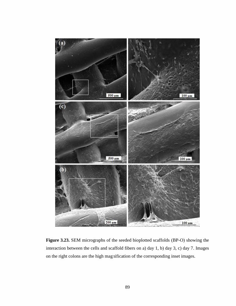
89
Figure 3.23. SEM micrographs of the seeded bioplotted scaffolds (BP-O) showing the
interaction between the cells and scaffold fibers on a) day 1, b) day 3, c) day 7. Images
on the right colons are the high magnification of the corresponding inset images.

90
3.8.2.3 Cell Proliferation on 3D Scaffolds
Proliferation ability of BMSCs on salt leached and bioplotted scaffolds is shown in
Figure 3.24. Results of day 1 show the initial cell attachment ability on individual
scaffold. It was observed that the initial attachment on SP5 and SP10 almost same,
while it was relatively lower on bioplotted scaffolds (BP-B and BP-O). Cell seeding
efficiency on bioplotted scaffolds was expected to be low due to very big pores which
leaded to flow of cell suspension to the well plate. This is obvious when BP-B and BP-
O scaffolds are compared. Initial cell attachment was influenced by whether offset
architecture was present or not. The number of initially attached cells was significantly
higher on BP-O scaffolds than that of BP-B scaffolds due to higher available fiber
surface area on the flow path of the cell suspension. If there is no fiber positioned as
offset, there is a direct open path for cells to escape from the scaffolds. On the other
hand, fibers in offset position, act as a barrier to prevent cell flow which further leads to
higher number of initial adhesion and proliferation. On all scaffolds, cells were able to
proliferate up to 21 days, which indicate good cell-material interactions. On day 21, a
small decrease in cell number was observed for SP5 which can be attributed to lower
interconnectivity compared to other constructs. All scaffolds displayed a sharp increase
in cell number after 7 days of culture. Based on initial cell number, bioplotted scaffolds
exhibited better proliferation rate than salt leached scaffolds. BP-B and BP-O showed
similar trend but, SP10 showed slightly higher proliferation rate than SP5. This is most
probably due higher interconnection pore size within bioplotted scaffolds which
enhanced the proliferation of cells by allowing greater diffusion of nutrients and waste.
After day 7, a decrease in cell growth rate was observed for all samples. Cell
proliferation rate is known to decrease during expression of differentiation factors.

91
Figure 3.24. Proliferation of BMSCs on 3D scaffolds (n=3).
3.8.2.4 von Kossa Staining
The ability of cells to produce mineralised matrix and calcium nodules is an indicator
for bone formation in vitro. In literature, mineralization is stated in different ways like
calcification, mineral deposition, calcium salts, mineralized matrix and bone nodule
formation. There are several methods used for detection of mineralization. These
include von Kossa staining, haemotxylin staining, EDX analysis, FTIR and X-ray
diffraction where von Kossa staining method has been widely used to examine
mineralization in vitro. It is an inexpensive technique, which require only a simple light
microscopy as an instrumentation. Various osteoblast and osteoblast-like cells have
been reported to form matrix-mediated mineral based on von Kossa staining [184].
However, the method provide a quantitative measurement of mineralization.
0
50000
100000
150000
200000
250000
300000
350000
400000
Day 1 Day 7 Day 14 Day 21
Cel
l n
um
ber
SP5
SP10
BP-B
BP-O

92
In this study, von Kossa staining for mineralisation was positive for all scaffolds, with
the most intense staining in bioplotted scaffolds. After staining, calcium salts are
coloured as dark brown or black. Significant amounts of black-stained deposits were
observed after 35 days of culture on 3D scaffolds which indicates that the seeded
osteoblasts produced mineralized tissues. Light microscopy images showed that small
nodules were formed on SP5, while some relatively larger nodules were observed
beside small ones on SP10 (Figure 3.25 b and c, respectively).
von Kossa staining indicated more extensive mineralization of osteoblasts on bioplotted
scaffolds. As seen in Figure 3.26 b-c, black deposits was covered all the surfaces of
fibers at upside and underside of bioplotted scaffolds, while no apparent positive
staining was observed on unseeded controls (Figure 3.26 a). These results suggest that
BMSCs were able to differentiate into osteogenic lineage in vitro. This suggestion was
further supported by SEM/EDX results.

93
Figure 3.25. von Kossa staining of mineralization on salt leached scaffold after 5
weeks of culture. a) Unseeded negatif control (SP5), b) SP5 and c) SP10. Arrows
indicate mineralized nodules.
a)
b) c)
100 µm
100µm 100 µm

94
Figure 3.26. von Kossa staining of mineralization on BP-O scaffolds after 5 weeks of
culture. a) Unseeded negative control, b) Focus on upside fiber surface, b) Focus on
underside fiber surface (Scale bar = 200 µm, insets = 100 µm).
a)
c) b)
200µm 200 µm
100µm
95
3.8.2.5 SEM/EDX Imaging of Mineralization on 3D Scaffolds
SEM/EDX analysis was performed in conjunction with von Kossa staining in order to
confirm the mineralization. Figure 3.27 and Figure 3.28 show morphological
observation of mineral deposition on salt leached spongy and bioplotted scaffolds,
respectively. At the end of 5 weeks, it is noticeable that all constructs were covered
with multilayers of cells and cells started filling up the pores with extracellular matrix
and abundant mineral deposits, indicating well cell attachment and proliferation of
osteoblasts. SEM images demonstrated that extracellular mineral deposition was higher
on bioplotted scaffolds than on salt leached scaffolds, which was also confirmed by
analyzing the seeded scaffolds’ surfaces via SEM/EDX imaging, that provides
determination of chemical composition of material surfaces (Figure 3.29). The amount
of elemental Ca and P was measured from the mineral nodules synthesized by
osteoblasts on surfaces of different scaffolds, and weight percentage of elements
measured on day 1 and day 35 are tabulated in Table 3.7. It is known that calcium and
phosphate serves as the nucleating agent for the formation of bone HAp. EDX analysis
verify the presence of calcium and phosphorous on the surface of all scaffolds after five
weeks of culture, while these elements were not detected on day 1, since there was no
mineral deposition yet. EDX detected low level of Ca and P deposition on salt leached
scaffolds compared to bioplotted scaffolds after 35 days of cultivation. Moreover, EDX
analysis revealed that Ca/P ratio of BP-O (~1.60) was close to the value attributed to
HAp (1.67), whereas Ca/P ratios of SP5 and SP10 (~0.55 for both) were very low
compared to that of HAp.
These results indicate that higher mineralization on bioplotted scaffolds might be
resulted from matrice stiffness. It has been stated that substrate stiffness can influence
the morphology and cell specific protein expression. Of course, responses to
mechanical stimuli vary with different cell type. For example, Flanagan et al. (2002)
showed that motor neurons derived from embryonic mouse spinal cord had preferred
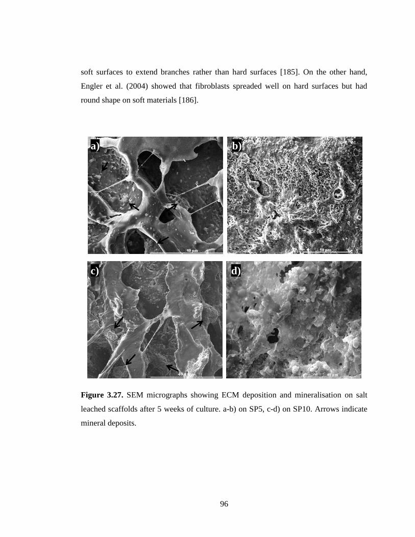
96
soft surfaces to extend branches rather than hard surfaces [185]. On the other hand,
Engler et al. (2004) showed that fibroblasts spreaded well on hard surfaces but had
round shape on soft materials [186].
Figure 3.27. SEM micrographs showing ECM deposition and mineralisation on salt
leached scaffolds after 5 weeks of culture. a-b) on SP5, c-d) on SP10. Arrows indicate
mineral deposits.
a) b)
c) d)

97
Figure 3.28. SEM micrographs showing ECM deposition and mineralisation on
bioplotted scaffolds (BP-O) after 35 days of culture. a-b) Top view, c-d) and e-f) Side
view of ECM deposition.
a) b)
c) d)
e) f)

98
Table 3.7. Weight percentage of C, O, P and Ca elements on different scaffolds seeded
with BMSCs
SP5 SP10 BP-O
Element Day 1 Day 35 Day 1 Day 35 Day 1 Day 35
C 71.59 49.54 62.30 49.11 67.86 38.23
O 28.41 39.62 37.47 31.66 31.81 33.64
P 0.00 6.95 0.00 12.36 0.00 10.83
Ca 0.00 3.89 0.23 6.87 0.33 17.31

99
keV
Figure 3.29. EDX measurement for the detection of mineralization on a) SP5, b)
SP10), c) BP-O on day 1 (left column) and on day 35 (right column).

100
3.8.3 Effect of Cell Proliferation on Compressive Properties of 3D PEU Matrices
The mechanical performances of BMSC seeded 3D scaffolds were characterized under
wet conditions after 1, 21 and 35 days of cultivation. In natural tissues, ECM provides
compressive strength to tissues [187]. Increase of compressive stiffness of scaffolds
after in vitro cell culture is an indication of ECM deposition by proliferated cells.
Figure 3.30 and Figure 3.31 show the influence of cell proliferation/matrix
mineralization on salt leached and on bioplotted scaffolds, respectively. Compressive
modulus of seeded scaffolds on day 1, day 21 and day 35 were compared in Table 3.8.
While compressive modulus of SP5 increased from 25.6±3.83 kPa to 35.01±2.82 kPa
that of SP10 changed from 16.38±3.20 kPa to 25.01±4.21 kPa after 21 days of cell
culture. Moreover, compressive moduli were increased to 44.44±3.48 kPa and
37.40±3.94 kPa for SP5 and SP10, respectively, with further cultivation up to 35 days.
Compressive moduli increased by 36% and 73% for SP5 and by 53% and 98% for
SP10 after 21 and 35 days of cultivation, respectively. The higher increase in the
mechanical properties of SP10 was most probably due to its more porous structure
compared to SP5 and this might have resulted in a higher cell penetratration and
proliferation throughout the scaffold, thus larger amount of ECM deposition after cell
culture up to 35 days. This is in agreement with the study of Lien et al. (2010), in
which they reported that chondrocyte seeded gelatin scaffolds with higher pore size
showed higher compression strength after cell culture compared to scaffolds with
smaller pore size [188].
For bioplotted ones, after 35 days of cultivation, compressive moduli of BP-B and BP-
O were increased from 4610±520 kPa (day 1) to 5095±614 kPa (day 35) and from
3535±437 kPa (day 1) to 3893±382 kPa (day 35) for BP-B and BP-O, respectively
(Table 3.8). For both BP-B and BP-O scaffolds, the increase was approximately 10%.

101
As is seen from these results, percent increase in compressive strength after cell culture
was more remarkable in salt leached scaffolds than it was in bioplotted ones. This is
because there is a big difference between the initial stiffness of salt leached scaffolds
and bioplotted ones. However, when total increase was taken into consider, it is
obvious that amount of increase in compressive strength was much higher on bioplotted
scaffolds.
It is not true to evaluate the efficacy of osseous tissue ingrowth by taking the initial
mechanical property as the only criterion. For example, it has been demonstrated that
biphasic calcium phosphate ceramics (BCP) with low microporosity and high
mechanical strength showed low bioresorption and bioactivity after implantation, while
BCP with initially higher microporosity and lower mechanical strength, revealed two or
three times mechanical increase after implantation. The researchers indicated that
highly macroporous BCP promoted higher ECM deposition in vivo and better
integration with native tissue [189].
Table 3.8. Change in compressive moduli of seeded 3D scaffolds by time
Sample E´ (kPa)
Day 1 Day 21 Day 35
SP5 25.6 ± 3.83 35.01 ± 2.82 44.44 ± 3.48
SP10 16.38 ± 3.20 25.01 ± 4.21 37.40 ± 3.94
BP-B 4610 ± 520 - 5095 ± 614
BP-O 3535 ± 437 - 3893 ± 382

102
Figure 3.30. Comparison of compressive moduli of seeded salt leached scaffolds on
day 1, day 21 and day 35 under wet conditions.
Figure 3.31. Comparison of compressive moduli of seeded bioplotted scaffolds on day
1 and on day 35 under wet conditions.
0
10
20
30
40
50
60
Seeded day 1 Seeded-day 21 Seeded-day 35
Com
pre
ssiv
e m
od
ulu
s (k
Pa)
SL5
SL10
0
1000
2000
3000
4000
5000
6000
Seeded day1 Seeded day 35
Com
pre
ssiv
e m
od
uu
ls (
kP
a)
BP-B
BP-O

103
CHAPTER 4
CONCLUSIONS
With advancements in tissue engineering it has become necessary to develop polymers
that meet more demanding requirements. Biodegradable synthetic polymers are
attractive materials for developing scaffolds in tissue engineering because of their
advantageous abilities like tailoring of mechanical properties and degradation kinetics
for a target application. Therefore, quite a number of biodegradable synthetic polymers
have been studied either as 2D or 3D scaffold for tissue engineering. A vast majority of
them belongs to the polyesters like poly(lactide), poly(glycolide), and their copolymers.
Among the wide polyester family, polyurethanes are one of the most popular group of
biomaterials used for the development of medical devices, due to their versatility in
chemical, physical and mechanical properties, and moderately good
haemocompatibility and biocompatibility.
In tissue engineering applications, designing and fabrication of an optimum scaffold is
a complex task. Depending on material properties, different manufacturing routes, and
processing conditions have been utilized to fabricate three dimensional scaffolds for
tissue engineering applications. In addition to other factors, these kinds of
manufacturing routes, and processing conditions influence the surface texture, surface
chemistry, crystallinity and microstructure of the resultant scaffolds which all influence
the cell response. Beside the chemistry of the biomaterial, understanding of cell-
substrate interactions is also important in the development of scaffolds for tissue
engineering. The relationship of many cells with scaffold construction parameters
influences expression of osteogenic factors. Parameters like fabrication factors,
specifically scaffold design parameters including porosity, pore size, scaffold

104
interconnectivity, and mechanical strength (stiffness), may affect the osteogenic
differentiation on scaffolds.
In the present study, an elastic lysine based poly(ester-urethane) (PEU) was
synthesized. The resultant polymer was fully characterized in order to explore its
suitability for tissue engineering applications. The polymer was assessed by fabrication
smooth and micropatterned 2D film; and macroporous 3D structures. 3D structures
were obtained by using traditional freeze drying and salt leaching techniques and
advanced bioplotting technique.
Thermal analyses results demonstrated that 2D and 3D matrices were stable at body
temperature and the synthesized polymer was suitable for melt processing. Tensile test
and DMA analyses of PEU films indicated that the polymer was highly elastic and
would be useful in low-temperature applications.
The 3D scaffolds had various pore sizes and porosity with different compressive
modulus. The bioplotted scaffolds were obtained with almost uniform pore size, while
freeze dried and salt leached scaffolds were obtained with inhomogeneous pore size
distribution. The bioplotted scaffolds exhibited significantly higher compressive
moduli than freeze dried and salt leached scaffolds due to stiffer nature of the
bioplotted fibers. Freeze dried sponges were not evaluated for in vitro studies since
they were not expected to support cell infiltration within the scaffolds because of their
considerably low pore size and porosity.
In vitro culture tests were carried on both 2D and 3D structures. On 2D films effect of
micropatterning and fibrinogen coating was evaluated in terms of osteoblastic function.
Regardless of physical and chemical modification, PEU film surfaces demonstrated
good compatability in terms of cell attachment and proliferation. Micropatterning on
the film surfaces led to cell alingnment along the parallel grooves; however it did not

105
make any difference in the sense of osteoblastic differentiation. On the contrary,
fibrinogen adsorption enhanced initial cell attachment and osteogenic activity.
Bioplotted and salt leached scaffolds were compared for their ability to promote
osteogenesis of BMSCs. Alamar cell viability test showed that all scaffolds allowed
cellular attachment, proliferation and osteogenic differentiation. Due to their higher
pore size and interconnectivity, proliferation rate was higher on bioplotted scaffolds
than that of salt leached scaffolds. Among the salt leached scaffolds, constructs with
higher porosity (96%) showed better proliferation compared to constructs with lower
porosity (85%) probably because of higher pore interconnectivity. SEM images
demonstrated that the cells cultured on all 3D scaffolds showed good cell proliferation
and mineralised extracellular matrix deposition. von Kossa staining results indicated
that calcium deposition was more abundant on bioplotted scaffolds than on salt leached
constructs. EDX results further supported the von Kossa staining of mineralization by
qualitative and quantitative analysis of calcium and phosphate expression, with the
highest calcium concentration measured on bioplotted scaffolds. It was concluded that
the substrate stiffness of bioplotted scaffolds may have enhanced the osteogenic
activity. As a result, all PEU based scaffolds, especially bioplotted ones possess a great
potential for adhesion, proliferation and mineralization of osteoblasts and are promising
for non-load bearing bone tissue engineering. However, it should be considered that
substrate stiffness is an important parameter in osteoblastic differentiation. Therefore,
both the underlying material and processing technique have a crucial interplay with
each other and should be taken into consideration while designing a scaffold for bone
tissue engineering applications.
In this study, it was shown that poly(ester-urethane) synthesized from
lysinediisocyanate and polycaprolactone diol is a biocompatible polymer and can be
shaped in different designs to form scaffolds. It was also shown that bone marrow stem
cells can proliferate and differentiate forming osteoblasts and forming calcium

106
phosphate deposits on the scaffolds. The future studies should consider in vivo and
further histological experiments in animals.
107
REFERENCES
[1] Penninger C.L., An investigation in the cellular mechanisms of bone remodeling
using a hybrid cellular automation approach, PhD Thesis, University of Notre
Dame, 2011.
[2] Hollinger J.O., Einhorn T.A., Doll B., Sfeir T., editors. Bone tissue engineering,
CRC Press, Florida, 2005.
[3] http://classroom.burnet.txed.net/webs/bbarnett/upload/ap_ch_5_notes_bones.pdf
(last visited on 7 July 2011)
[4] Wang X., Nyman J.S., Dong X., Leng H. Fundamental Biomechanics in Bone
Tissue Engineering.Morgan & Claypool, Davis, 2010.
[5] Notelovitz M. Androgen effects on bone and muscle. Science, 77: 34-41, 2002
[6] Jäger I., Peter F. Mineralized Collagen Fibrils: A Mechanical Model with a
Staggered Arrangement of Mineral Particles. Biophysical Journal, 79: 1737-
1746, 2000.
[7] Murugan R., Ramakrishna S. Development of nanocomposites for bone grafting.
Composites Science and Technology, 65: 2385-2406, 2005.
[8] Basu B., Katti D., Kumar A., ed., Advanced Biomaterials: Fundamentals,
Processing and Applications, New Jersey, USA: John Wiley & Sons, 2009.
[9] M.D. Robert Proulx Heaney, M.D., G. Donald Whedon. Encyclopædia
Britannica, 2011.
[10] Zysset P.K., Guo X.E., Ho C.E., Moore K.E., Goldstein S.A. Elastic modulus
and hardness of cortical and trabecular bone lamellae measured by
nanoindentation in the human femur. Journal of Biomechanics, 32: 1005-1012,
1999.
[11] Caplan A.I. Embryonic development and the principles of tissue engineering.
Tissue Engineering of Cartilage and Bone, Gregory Bock and Jamie Goode,
eds., Chichester, UK:, pp. 17-33, 2003.

108
[12] Wahl D.A., Czernuszka J.T. Collagen-hydroxyapatite composites for hard tissue
repair. European Cells and Materials, 11: 43-56, 2006.
[13] Marquass B., Somerson J.S., Hepp P., Aigner T., Schwan S., Bader A., Josten
C., Zscharnack M., Schulz R.M. A novel MSC-seeded triphasic construct for the
repair of osteochondral defects. Journal of Orthopaedic Research:Official
Publication of The Orthopaedic Research Society, 28: 1586-99, 2010.
[14] Gorokhovsky A.V., Cortes-Hernandez, D.A., Shcherbakova N.N. Composites
from mixtures of potassium polytitanate and biocompatible glasses. Glass and
Ceramics, 67: 358-360, 2011.
[15] Weiner S., Traub W. Organization of hydroxyapatite crystals within collagen
fibrils. FEBS Letters, 206: 262-266, 1986.
[16] Landis W.J., Hodgens K.J., Arena J., Song M.J., McEwen B.F. Structural
relations between collagen and mineral in bone as determined by high voltage
electron microscopic tomography. Microscopy Research and Technique, 33:
192-202, 1996.
[17] Sasaki N., Matsushima N., Ikawa N., Yamamura H., Fukuda A. Orientation of
bone mineral and its role in the anisotropic mechanical properties of bone—
Transverse anisotropy. Journal of Biomechanics, 22: 157-164, 1989.
[18] Badylak S.F. The extracellular matrix as a scaffold for tissue reconstruction.
Seminars in Cellular and Developmental Biology, 13: 377-383, 2002.
[19] Lutolf M.P., Hubbell J.A. Synthetic biomaterials as instructive extracellular
microenvironments for morphogenesis in tissue engineering. Nature
Biotechnology, 23: 47-55, 2005.
[20] Metcalfe A.D., Ferguson, M.W.J. Tissue engineering of replacement skin: the
crossroads of biomaterials, wound healing, embryonic development, stem cells
and regeneration. Journal of the Royal Society, Interface/the Royal Society, 4:
413-37, 2007.
[21] Fernandes H., Moroni, van Blitterswijk C. L., de Boer J. Extracellular matrix
and tissue engineering applications. Journal of Materials Chemistry, 19: 5474,
2009.
[22] Lutter A.-H., Hempel U., Wolf-Brandstetter C., Garbe A.I., Goettsch C.,.
Hofbauer L.C, Jessberger R., Dieter P. A novel resorption assay for osteoclast

109
functionality based on an osteoblast-derived native extracellular matrix. Journal
of Cellular Biochemistry, 109: 1025-32, 2010.
[23] Allori W.S., Sailon AC., Biological basis of bone formation, remodeling, and
repair-Part II: Extracellular matrix,‖ Tissue Eng Part B, 14; 275–283, 2008.
[24] Eckstein F., Matsuura M., Kuhn V., Priemel M., Link T.M. Sex Differences of
Human Trabecular Bone Microstructure in Aging Are Site-Dependent. Journal
of Bone and Mineral Research, 22: 817-824, 2007.
[25] Stauber M., Müller R. Age-related changes in trabecular bone microstructures :
global and local morphometry. Osteoporosis International, 17: 616-626, 2006.
[26] Bousson V., Peyrin F., Bergot C., Hausard M., Sautet A., Laredo J.-D. Cortical
Bone in the Human Femoral Neck: Three-Dimensional Appearance and Porosity
Using Synchrotron Radiation. Journal of Bone and Mineral Research, 19: 794-
801. 2004.
[27] Mosekilde L. Age-related changes in bone mass, structure, and strength effects
of loading. Zeitschrift Fur Rheumatologie, 59: 1-9, 2000.
[28] http://www.devicelink.com/news/100/2/27291.html (last visited on 7 July 2011).
[29] Stevens M.M. Biomaterials for bone tissue engineering, Materials Today, 11:
18-25, 2008.
[30] Hubbell J.A. Bioactive biomaterials. Current Opinion in Biotechnology, 10: 123-
129, 1999.
[31] Bueno E.M., Glowacki J. Biologic Foundations for Skeletal Tissue Engineering,
Davis, USA: Morgan & Claypool, 2011.
[32] Glowacki J., Mulliken J.B. Demineralized bone implants, Clin Plast Surg, 12:
233-241, 1985.
[33] Robertson P.A., Wray A.C. Natural history of posterior iliac crest bone graft
donation for spinal surgery: a prospective analysis of morbidity. Spine, 26: 1473-
1476, 2001.
[34] De Long W.G.D., Einhorn T.A., Koval K., Mckee M., Smith W., Sanders R.,
Watson T. Bone Grafts and Bone Graft Substitutes in Orthopaedic Trauma
Surgery, A critical analysis. J Bone Joint Surg Am, 89: 649-658, 2007.

110
[35] Saffarzadeh A., Gauthier O., Bilban M., Arc M. B. D., Daculsi G. Comparison
of two bone substitute biomaterials consisting of a mixture of fibrin sealant
(Tisseel) and MBCPt (TricOs) with an autograft in sinus lift surgery in sheep.
Clinical Oral Implants Research, 20: 1133-1139, 2009.
[36] Bernhardt A., Lode A., Peters F., Gelinsky M. Novel ceramic bone replacement
material Osbone in a comparative in vitro study with osteoblasts. Clinical Oral
Implants Research, 22: 651-657, 2010.
[37] Aydin E., V. Hasirci. Biodegradable Hard Tissue Implants. Journal of Siberian
Federal University,1: 3-17, 2010.
[38] Anderson J.M. Biological responses to materials. Annual Review of Materials
Research, 31: 81-110, 2001.
[39] Williams D.F. Definitions in Biocompatibility, Amsterdam: Elsevier, 1987.
[40] Hench L.L., Wilson J., ed., An Introduction to Bioceramics, World Scientific,
Singapore, 1993.
[41] Rakhorst G., Ploeg R.J., ed., Biomaterials in Modern Medicine: The Groningen
perspective, London: World Scientific Publishing, 2007.
[42] Divisi D., Crisci R. Use of demineralized bone matrix and plate for sternal
stabilization after traumatic dislocation. Gen Thorac Cardiovasc Surg, 59: 52-
56,2011.
[43] Finkemeier C.G. Bone-Grafting and Bone-Graft Substitutes. The Journal of Bone
and Joint Surgery, 84A: 454-64, 2002.
[44] Bella C.D., Dozza B., Frisoni T., Cevolani L., Donati D. Injection of
Demineralized Bone Matrix With Bone Marrow Concentrate Improves Healing
in Unicameral Bone Cyst. Clinical Orthopaedics and Related Research, 468:
3047-3055, 2010.
[45] Jayasuriya A.C., Æ.N.A. Ebraheim. Evaluation of bone matrix and
demineralized bone matrix incorporated PLGA matrices for bone repair. Journal
of Materials Science: Materials in Medicine, 20: 1637-1644, 2009.
[46] Lin H., Zhao Y., Sun W., Chen B., Zhang J., Zhao W., Xiao Z., Dai J. The effect
of crosslinking heparin to demineralized bone matrix on mechanical strength and
111
specific binding to human bone morphogenetic protein-2. Biomaterials, 29:
1189-1197, 2008.
[47] Qiu Q.Q., Mendenhall H.V., Garlick D.S., Connor J. Evaluation of Bone
Regeneration at Critical-Sized Calvarial Defect by DBM / AM Composite.
Journal of Biomedical Materials Research, 81B: 516-523, 2007.
[48] Öztürk A., Yetkin H., Memis L., Cila E., Bolukbasi S., Gemalmaz C.
Demineralized bone matrix and hydroxyapatite / tri-calcium phosphate mixture
for bone healing in rats. International Orthopaedics, 30: 147-152, 2006.
[49] Peterson B., Whang P.G., Iglesias R., Wang J.C., Lieberman J.R.
Osteoinductivity of Commercially Available Demineralized Bone Matrix:
Preparations in a Spine Fusion Model. J Bone Joint Surg Am, 86A: 2243-50,
2004.
[50] Dorozhkin S.V. Calcium orthophosphates in nature, biology and medicine.
Materials, 2: 399-498, 2009.
[51] Schieker M., Seitz H., Drosse I., Seitz S., Mutschler W. Biomaterials as Scaffold
for Bone Tissue Engineering. European Journal of Trauma, 32: 114-124, 2006.
[52] Ogata K., Imazato S., Ehara A., Ebisu S., Kinomoto Y., Nakano T., Umakoshi
Y. Comparison of osteoblast responses to hydroxyapatite and
hydroxyapatite/soluble calcium phosphate composites. Journal of Biomedical
Materials Research. Part A, 72: 127-35, 2005.
[53] Basu, B., Katti D., Kumar A., ed., Advanced Biomaterials: Fundamentals,
Processing, and Applications, New Jersey, USA: John Wiley & Sons, 2009.
[54] Hench L.L. Bioceramics: From Concept to Clinic. Journal of the American
Ceramic Society, 74: 1487–1510, 1991.
[55] Le Guéhennec L., Layrolle P., Daculsi G. A Review of Bioceramics and Fibrin
Sealant, European Cells and Materials, 8: 1-10, 2004.
[56] Demers C., Hamdy C.R., Corsi K., Chellat F., Tabrizian M. Natural coral
exoskeleton as a bone graft substitute: a review. Biomedical Materials and
Engineering, 12: 15-35, 2002.
[57] Wu Y.-C., Lee T.-M., Chiu K.-H., Shaw S.-Y., Yang C.-Y. A comparative study
of the physical and mechanical properties of three natural corals based on the

112
criteria for bone – tissue engineering scaffolds. Journal of Materials Science:
Materials in Medicine, 20: 1273-1280, 2009.
[58] Hejazi R., Amiji M. Chitosan-based gastrointestinal delivery systems. Journal of
Controlled Release, 89: 151-165, 2003.
[59] Arinzeh T.L., Tran T.; Mcalary J., Daculsi G. A comparative study of biphasic
calcium phosphate ceramics for human mesenchymal stem cell-induced bone
formation. Biomaterials, 26: 3631-3638, 2005.
[60] Burg K.J.L., Porter S., Kellam J.F. Biomaterial developments for bone tissue
engineering. Biomaterials, 21: 2347-2359, 2000.
[61] Tuan R.S., Boland G., Tuli R. Adult mesenchymal stem cells and cell-based
tissue engineering. Arthritis Research and Therapy, 5: 32-45, 2003.
[62] Yucel D., Kose G.T., Hasirci V. Tissue engineered, guided nerve tube consisting
of aligned neural stem cells and astrocytes. Biomacromolecules, 11: 3584-91,
2010.
[63] Ma P.X., Elisseeff J.ed. Scaffolding in Tissue Engineering, 2004.
[64] Sokolsky-Papkov M., Agashi K., Olaye A., Shakesheff K., Domb A.J. Polymer
carriers for drug delivery in tissue engineering. Advanced Drug Delivery
Reviews, 59: 187-206, 2007.
[65] Kuboki Y., Takita H., Kobayashi D., Tsuruga E., Inoue M., Murata M., Nagai
N., Dohi Y., Ohgushi H. BMP-induced osteogenesis on the surface of
hydroxyapatite with geometrically feasible and nonfeasible structures: topology
of osteogenesis. Journal of Biomedical Materials Research, 39: 190-9, 1998.
[66] Lanza R., Langer R., Vacanti J.P., ed., Principles of Tissue Engineering,
Burlington, MA: Elsevier Academic Press, 2007.
[67] Jin Q.M., Takita H., Kohgo T., Atsumi K., Itoh H., Kuboki Y. Effects of
geometry of hydroxyapatite as a cell substratum in BMP-induced ectopic bone
formation. Journal of Biomedical Materials Research, 52: 491-9, 2000.
[68] Vogt S., Larcher Y., Beer B., Wilke I., Schnabelrauch M. Fabrication of highly
porous scaffold materials based on functionalized oligolactides and preliminary
results on their use in bone tissue engineering. European Cells and Materials, 4:
30-8, 2002.
113
[69] Lin L., Tong A., Zhang H., Hu Q., Fang M. The Mechanical Properties of Bone
Tissue Engineering Scaffold Fabricating Via Selective Laser Sintering. Life
System Modeling and Simulation, 4689: 146-152, 2007.
[70] Mao, J., Mikos A.G., Gordana V.-N., Antala, A., ed., Translational Approaches
in Tissue Engineering and Regenerative Medicine, Boston, Mass.; London:
Artech House, 2007.
[71] Isikli C., Hasirci V., Hasirci N.Development of porous chitosan–
gelatin/hydroxyapatite composite scaffolds for hard tissue-engineering
applications. Journal of Tissue Engineering and Regenerative Medicine,
10.1002/term.46, 2011.
[72] Gunatillake P.A., Adhikari R. Biodegradable synthetic polymers for tissue
engineering. European Cells and Materials, 5: 1-16, 2003.
[73] Santerre J.P., Woodhouse K., Laroche G., Labow R.S. Understanding the
biodegradation of polyurethanes: from classical implants to tissue engineering
materials. Biomaterials, 26: 7457-70, 2005.
[74] Oertel G. Polyurethane Handbook, Munich: Hanser Publishers, 1994.
[75] Hasirci N., Aksoy E.A. Synthesis and Modifications of Polyurethanes for
Biomedical Purposes. High Performance Polymers, 19: 621-637, 2007.
[76] Nair L., Laurencin C. Biodegradable polymers as biomaterials. Progress in
Polymer Science, 32: 762-798, 2007.
[77] Wheatley D.J., Raco L., Bernacca G.M., Sim I., Belcher P.R., Boyd J.S.
Polyurethane: material for the next generation of heart valve prostheses?
European journal of cardio-thoracic surgery: official journal of the European
Association for Cardio-thoracic Surgery, 17: 440-8, 2000.
[78] Stokes K., Cobian K. Polyether polyurethanes for implantable pacemaker leads.
Biomaterials, 3: 225-231, 1982.
[79] Gorman S.P., Jones D.S., Bonner, M.C., Akay M., Keane P.F. Mechanical
performance of polyurethane ureteral stents in vitro and ex vivo. Biomaterials,
18: 1379-1383, 1997.
[80] Gogolewski S., Gorna K., Turner A.S. Regeneration of bicortical defects in the
iliac crest of estrogen-deficient sheep, using new biodegradable polyurethane
114
bone graft substitutes. Journal of Biomedical Materials Research Part A, 77A:
802-810 ,2006.
[81] Huynh T.T., Padois K., Sonvico F., Rossi A., Zani F., Pirot F., Doury J., Falson
F. Characterization of a polyurethane-based controlled release system for local
delivery of chlorhexidinediacetate. European Journal of Pharmaceutics and
Biopharmaceutics. 74: 255-264, 2010.
[82] Storey R.F., Wiggins J.S., Puckett A.D. Hydrolyzable poly(ester-urethane)
networks from L-lysine diisocyanate and D,L-lactide/ε-caprolactone homo- and
copolyestertriols. Journal of Polymer Science Part A: Polymer Chemistry, 32:
2345-2363, 1994.
[83] Han J., Chen B., Ye L., Zhang A.Y., Zhang J., Feng Z.G. Synthesis and
characterization of biodegradable polyurethane based on poly(ε-caprolactone)
and L-lysine ethyl ester diisocyanate. Frontiers of Materials Science in China, 3:
25-32, 2009.
[84] Guelcher S.A., Srinivasan A., Dumas J.E., Didier J.E., McBride S., Hollinger
J.O. Synthesis, mechanical properties, biocompatibility, and biodegradation of
polyurethane networks from lysine polyisocyanates. Biomaterials, 29: 1762-
1775, 2008.
[85] Marcos-Fernandez A., Abraham G.A., Valentin J.L., San Roman J. Synthesis
and characterization of biodegradable non-toxic poly(ester-urethane-urea)s based
on poly(ε-caprolactone) and amino acid derivatives. Polymer, 47: 785-798,
2006.
[86] Ciardelli G., Rechichi A., Cerrai P., Tricoli M., Barbani N., Giusti P. Segmented
polyurethanes for medical applications: synthesis, characterization and in vitro
enzymatic degradation studies. Macromolecular Symposia, 169: 261-272, 2004.
[87] Gogolewski S., Gorna K. Biodegradable polyurethane cancellous bone graft
substitutes in the treatment of iliac crest defects. J Biomed Mater Res A. 80: 94-
101, 2007.
[88] Hafeman A.E., Li B., Yoshii T., Zienkiewicz K., Davidson J.M., Guelcher S.A.
Injectable biodegradable polyurethane scaffolds with release of platelet-derived
growth factor for tissue repair and regeneration. Pharmaceutical Research, 25:
2387-2399, 2008.

115
[89] Jian Z.Y., Chang J.K., Shau M.D. Synthesis and characterizations of new lysine-
based biodegradable cationic poly(urethane-co-ester) and study on self-
assembled nanoparticles with DNA. Bioconjugate Chemistry, 20: 774-779, 2009.
[90] Guelcher S.A. Biodegradable polyurethanes: synthesis and applications in
regenerative medicine. Tissue Eng Part B Rev., 14: 3-17, 2008.
[91] Zhang Y., Zhang M. Three-dimensional macroporous calcium phosphate
bioceramics with nested chitosan sponges for load-bearing bone implants.
Journal of Biomedical Materials Research, 61: 1-8, 2002.
[92] Grad S., Kupcsik L., Gorna K., Gogolewski S., Alini M. The use of
biodegradable polyurethane scaffolds for cartilage tissue engineering: potential
and limitations. Biomaterials, 24: 5163-5171, 2003.
[93] Cui T., Yan Y., Zhang R., Liu L., Xu W., Wang X. Rapid prototyping of a
double-layer polyurethane-collagen conduit for peripheral nerve regeneration.
Tissue Eng Part C Methods, 15: 1-9, 2009.
[94] Riboldi S.A., Sampaolesi M., Neuenschwander P., Cossu G., Mantero S.
Electrospun degradable polyesterurethane membranes: potential scaffolds for
skeletal muscle tissue engineering. Biomaterials, 26: 4606-4615, 2005.
[95] Kavlock K.D., Pechar T.W., Hollinger J.O., Guelcher S.A., Goldstein A.S.
Synthesis and characterization of segmented poly(esterurethane urea) elastomers
for bone tissue engineering. Actabiomaterialia, 3: 475-484, 2007.
[96] Baker S.C., Rohman G., Southgate J., Cameron N.R. The relationship between
the mechanical properties and cell behaviour on PLGA and PCL scaffolds for
bladder tissue engineering. Biomaterials, 30: 1321-1328, 2009.
[97] Mano J., Sousa R.A., Boesel L.F., Neves N.M., Reis R.L. Bioinert,
biodegradable and injectable polymeric matrix composites for hard tissue
replacement: state of the art and recent developments. Composites Science and
Technology, 64: 789-817, 2004.
[98] Loh X.J., Peh P., Liao S., Sng C., Li J. Controlled drug release from
biodegradable thermoresponsive physical hydrogel nanofibers. Journal of
Controlled Release, 143: 175-182, 2010.

116
[99] Bruin P., Veenstra G.J., Nijenhuis A.J., Pennings A.J. Design and synthesis of
biodegradable poly(ester-urethane) elastomer net- works composed of non-toxic
building blocks. Makromol Chem, Rapid Commun, 9: 589-594, 1988.
[100] Braccini A., Wendt D., Jaquiery C., Jakob M., Heberer M., Kenins L., Wodnar-
Filipowicz A., Quarto R., Martin I. Three-dimensional perfusion culture of
human bone marrow cells and generation of osteoinductive grafts. Stem Cells,
23: 1066-1072, 2005.
[101] Pirraco R.P., Marques A.P., Reis R.L. Cell interactions in bone tissue
engineering. Journal of Cellular and Molecular Medicine, 14: 93-102, 2010.
[102] Luu H.H., Song W.X., Luo X., Manning D., Luo J., Deng Z.L., Sharff K.A.,
Montag A.G., Haydon R.C., He T.C. Distinct Roles of Bone Morphogenetic
Proteins in Osteogenic Differentiation of Mesenchymal Stem Cells. Journal of
Orthopaedic Research, 25: 665-677, 2007.
[103] Basmanav F.B., Kose G.T., Hasirci V. Sequential growth factor delivery from
complexed microspheres for bone tissue engineering. Biomaterials, 29: 4195-
4204, 2008.
[104] Yilgor P., Hasirci N., Hasirci V. Sequential BMP-2 / BMP-7 delivery from
polyester nanocapsules. Journal of Biomedical Materials Research Part A, 93:
528-536, 2010.
[105] Heinemann C., Heinemann S., Worch H., Hanke T. Development of an
osteoblast / osteoclast co-culture derived by human bone marrow stromal cells
and human monocytes for biomaterials testing. Eur Cell Mater. 21: 80-93, 2011.
[106] Nuttelman C.R., Tripodi M.C., Anseth K.S. Dexamethasone-functionalized gels
induce osteogenic differentiation of encapsulated hMSCs. Journal of Biomedical
Materials Research, 76: 183-195, 2006.
[107] Son E., Do H., Joo H.M, Pyo S. Induction of alkaline phosphatase activity by L -
ascorbic acid in human osteoblastic cells: a potential role for CK2 and Ikaros.
Nutrition, 23: 745-753, 2007.
[108] Otsuka E., Kato Y., Hirose S., Hagiwara H. Role of ascorbic acid in the
osteoclast formation: induction of osteoclast differentiation factor with formation
of the extracellular collagen matrix. Endocrinology, 141: 3006-3011, 2000.

117
[109] Mao J.J., Vunjak-Novakovic G., Mikos A.G., Atala A. ed. Scaffolds with
designed architecture: Effect on Scaffold Function and Tissue Regeneration.
Translational Approaches in Tissue Engineering and Regenerative Medicine,
2008.
[110] Liu X., Ma P.X. Polymeric scaffolds for bone tissue engineering. Annals of
Biomedical Engineering, 32: 477-486, 2004.
[111] Meyer U., Wiesmann H.P., Bone and Cartilage Engineering, Springer, Münster,
Germany, 2006.
[112] Lam C.X.F., Mo X.M., Teoh S.H., Hutmacher D.W. Scaffold development using
3D printing with a starch-based polymer Materials Science and Engineering: C,
20: 49-56, 2002.
[113] Sachlos E., Czernuszka J.T. Making tissue engineering scaffolds work. Review:
the application of solid freeform fabrication technology to the production of
tissue engineering scaffolds. European Cells & Materials, 5:29-40, 2003.
[114] Chung C., Burdick J.A. Engineering cartilage tissue. Advanced Drug Delivery
Reviews, 60: 243 - 262, 2008.
[115] Mikos A.G., Bao Y., Cima L.G., Ingber D.E., Vacanti J.P., Langer R.
Preparation of poly(glycolic acid) bonded fi ber structures for cell attachment
and transplantation J. Biomed. Mater. Res, 27: 183-189, 1993.
[116] Kose G.T., Kenar H., Hasirci N., Hasirci V. Macroporous poly(3-
hydroxybutyrate-co-3-hydroxyvalerate) matrices for bone tissue engineering.
Biomaterials, 24: 1949-1958, 2003.
[117] Harris L.D., Kim B.S., Mooney D.J. Open pore biodegradable matrices formed
with gas foaming. J Biomed Mater Res, 42: 396-402, 1998.
[118] Brien F.J.O., Harley B.A., Yannas I.V., Gibson L.J. The effect of pore size on
cell adhesion in collagen-GAG scaffolds. Biomaterials, 26: 433-441, 2005.
[119] Ndreu A., Nikkola L., Ylikauppila H., Ashammakhi N., Hasirci V. Electrospun
biodegradable nanofibrous mats for tissue engineering. Nanomedicine, 3: 45-60,
2008.
[120] Padeste C., Ozcelik H., Ziegler J., Schleunitz A., Bednarzik M., Yucel D.,
Hasirci V. Replication of high aspect ratio pillar array structures in

118
biocompatible polymers for tissue engineering applications. Microelectronic
Engineering, 88: 1836-1839, 2011.
[121] Gomes M.E., Godinho J.S., Tchalamov D., Cunha A.M., Reis R.L. Alternative
tissue engineering scaffolds based on starch : processing methodologies ,
morphology, degradation and mechanical properties. Materials Science and
Engineering: C, 20: 19- 26, 2002.
[122] Yilgor P., Sousa R.A., Reis R.L., Hasirci N., Hasirci V. Effect of scaffold
architecture and BMP-2/BMP-7 delivery on in vitro bone regeneration. Journal
of Materials Science. Materials in medicine, 21: 2999-3008, 2010.
[123] Liulan L., Qingxi H., Xianxu H., Gaochun X., Design and Fabrication of Bone
Tissue Engineering Scaffolds via Rapid Prototyping and CAD. Journal of Rare
Earths, 25: 379-383, 2007.
[124] Hutmacher D.W., Sittinger M., Risbud M.V. Scaffold-based tissue engineering:
rationale for computer-aided design and solid free-form fabrication systems.
Trends in Biotechnology, 22: 354-362, 2004.
[125] Reignier J., Huneault M. Preparation of interconnected poly(ε-caprolactone)
porous scaffolds by a combination of polymer and salt particulate leaching.
Polymer, 47: 4703-4717, 2006.
[126] Giannatsis J., Dedoussis V. Additive fabrication technologies applied to
medicine and health care: a review. The International Journal of Advanced
Manufacturing Technology, 40: 116-127, 2007.
[127] Engelmayr G.C., Papworth G.D., Watkins S.C., Mayer J.E., Sacks M.S.
Guidance of engineered tissue collagen orientation by large-scale scaffold
microstructures. Journal of Biomechanics, 39: 1819-1831, 2006.
[128] Yilgor P., Sousa R.A., Reis R.L., Hasirci N., Hasirci V. 3D Plotted PCL
Scaffolds for Stem Cell Based Bone Tissue Engineering. Macromolecular
Symposia, 269: 92-99, 2008.
[129] Masood S.H., Singh J.P., Morsi Y. The design and manufacturing of porous
scaffolds for tissue engineering using rapid prototyping. International Journal of
Advanced Manufacturing Technology, 27: 415-420, 2005.

119
[130] Giordano R.A., Wu B.M., Borland S.W., Cima L.G., Sachs E.M., Cima M.J.
Mechanical properties of dense polylactic acid structures fabricated by three
dimensional printing. J Biomater Sci Polym Ed, 8: 63-75, 1996.
[131] Kim S.S., Utsunomiya H., Koski J.A., Wu B.M., Cima M.J., Sohn J., Mukai K.,
Griffith L.G., Vacanti J.P. Survival and Function of Hepatocytes on a Novel
Three-Dimensional Synthetic Biodegradable Polymer Scaffold With an Intrinsic
Network of Channels. Annals of Surgery, 228: 8-13, 1998.
[132] Yeong W.Y., Chua C.K., Leong K.F., Chandrasekaran M. Rapid prototyping in
tissue engineering: challenges and potential. Trends in Biotechnology, 22: 643-
652, 2004.
[133] Landers R., Mulhaupt R. Desktop manufacturing of complex objects, prototypes
and biomedical scaffolds by means of computer-assisted design combined with
computer-guided 3D plotting of polymers and reactive oligomers.
Macromolecular Materials and Engineering, 282: 17-21, 2000.
[134] Bignon A., Chouteau J., Chevalier J., Fantozzi G., Carret J.P., Chavassieux P.,
Boivin G., Melin M., Hartmann D. Effect of micro- and macroporosity of bone
substitutes on their mechanical properties and cellular response. Journal of
materials science. Materials in Medicine, 14: 1089-1097, 2003.
[135] Zeltinger J., Sherwood J.K., Graham D.A., Mueller R., Griffith L.G. Effect of
pore size and void fraction on cellular adhesion, proliferation, and matrix
deposition. Tissue Engineering, 7: 557-572, 2001.
[136] Lu Q., Wang X., Lu S., Li M., Kaplan D.L., Zhu H. Nanofibrous architecture of
silk fibroin scaffolds prepared with a mild self-assembly process. Biomaterials,
32: 1059-1067, 2011.
[137] Flemming R.G., Murphy C.J., Abrams G.A., Goodman S.L., Nealey P.F. Effects
of synthetic micro- and nano-structured surfaces on cell behavior. Biomaterials,
20: 573-88 1999.
[138] Solchaga L.A., Gao J., Dennis J.E., Awadallah A., Lundberg M., Caplan A.I.,
Goldberg V.M. Treatment of osteochondral defects with autologous bone
marrow in a hyaluronan -based delivery vehicle Tissue Engineering, 8: 333-347,
2002.
[139] Kenar H., Köse G.T., Hasirci V. Tissue engineering of bone on micropatterned
biodegradable polyester films. Biomaterials, 27: 885-895, 2006.

120
[140] Hasirci N., Endogan T., Vardar E., Kiziltay A., Hasirci V. Effect of oxygen
plasma on surface properties and biocompatibility of PLGA films. Surface and
Interface Analysis, 42: 486-491, 2010.
[141] Walboomers X.F., Jansen J.A. Cell and tissue behavior on micro-grooved
surfaces. Odontology, 89: 2-11, 2001.
[142] Lim J.Y., Hansen J.C., Siedlecki C.A., Runt J., Donahue H.J. Human foetal
osteoblastic cell response to polymer-demixed nanotopographic interfaces.
Journal of the Royal Society, Interface, 2: 97-108, 2005.
[143] Berry C.C., Campbell G., Spadiccino A., Robertson M., Curtis A.S. The
influence of microscale topography on fibroblast attachment and motility.
Biomaterials, 25: 5781-5788, 2004.
[144] Van Kooten T.G., Whitesides J.F., von Recum A. Influence of silicone (PDMS)
surface texture on human skin fibroblast proliferation as determined by cell
cycle analysis. Journal of Biomedical Materials Research, 43: 1-14, 1998.
[145] Park J., Berthiaume F., Toner M., Yarmush M.L., Tilles A.W. Microfabricated
grooved substrates as platforms for bioartificial liver reactors. Biotechnology and
Bioengineering, 90: 632-644, 2005.
[146] Kanamori Y., Sato J., Shimano T., Nakamura S., Hane K. Polymer
microstructure generated by laser stereo-lithography and its transfer to silicon
substrate using reactive ion etching. Microsystem Technologies, 13: 1411-1416,
2007.
[147] Mcbeath R., Pirone D.M., Nelson C.M., Bhadriraju K., Chen C.S. Cell Shape,
Cytoskeletal Tension, and RhoA Regulate Stem Cell Lineage Commitment. Dev
Cell, 6: 483-495, 2004.
[148] Su W.T., Chu I.M., Yang J.Y., Lin C.D. The geometric pattern of a pillared
substrate influences the cell-process distribution and shapes of fibroblasts.
Micron, 37: 699-706, 2006.
[149] Khang G., Lee S.J., Jeon J.H., Lee J.H., Lee H.B. Interaction of fibroblast cell
onto physicochemically treated PLGA surfaces. Polymer (Korea), 24: 869-876,
2000.
121
[150] Bhati R.S., Mukherjee D.P., Mccarthy K.J., Rogers S.H., Smith D.F., Shalaby
S.W. The growth of chondrocytes into a fibronectin-coated biodegradable
scaffold. J Biomed Mater Res, 56: 74-82, 2001.
[151] Prime K.L., Whitesides G M., Self-assembled organic monolayers: model
systems for studying adsorption of proteins at surfaces. Science, 252: 1164-1167,
1991.
[152] Athanasiou K.A., Darling E.M., Hu J.C. Articular Cartilage Tissue Engineering,
Davis, USA: Morgan & Claypool, 2010.
[153] Hasirci V., Tezcaner A., Hasirci N., Suzer S. Oxygen plasma modification of
poly(3-hydroxybutyrate-co-3-hydroxyvalerate) film surfaces for tissue
engineering purposes. Journal of Applied Polymer Science, 87: 1285-1289,
2003.
[154] Bumgardner J.D., Wiser R., Elder S.H., Jouett R. Contact angle , protein
adsorption and osteoblast precursor cell attachment to chitosan coatings bonded
to titanium. J Biomater Sci Polym Ed., 14: 1401- 1409, 2003.
[155] Hasirci V., Tezcaner A. Yaszemski M.J., Trantolo D.J, Lewandrowski K.,
Hasirci V, Altobelli D.E., Wise D.L., ed. Surface Properties of Polymeric
Biomaterials and Their Modification for Tissue Engineering Applications.
Tissue Engineering and Novel Delivery Systems, CRC Press, 2003
[156] Hong S., Lin Y.C., Lin C.H. Crystallization and degradation behaviors of treated
polyhydroxybutyrates,‖ Reactive and Functional Polymers, 68: 1516-1523,
2008.
[157] Hassan M.K., Mauritz K.A., Storey R.F., Wiggins J.S. Biodegradable Aliphatic
Thermoplastic Polyurethane Based on Poly ( e-caprolactone ) and L -Lysine
Diisocyanate. Journal of Polymer Science Part A-polymer Chemistry, 44: 2990-
3000, 2006.
[158] Yi J., Boyce M., Lee G., Balizer E. Large deformation rate-dependent stress –
strain behavior of polyurea and polyurethanes. Polymer, 47: 319-329, 2006.
[159] D.M. Crawford, Bass R.G., Haas T.W. Strain effects on thermal transitions and
mechanical properties of thermoplastic polyurethane elastomers,‖
Thermochimica Acta, 323: 53-63, 1998.

122
[160] ―Standard Guide for Assessing Microstructure of Polymeric Scaffolds for Use in
Tissue Engineered Medical Products,‖ ASTM F2450 - 10.
[161] Hing K.A. Bioceramic Bone Graft Substitutes: Influence of Porosity and
Chemistry. International Journal of Applied Ceramic Technology, 2: 184-199,
2005.
[162] Hing K.A., Best S.M., Bonfield W. Characterization of porous hydroxyapatite.
Journal of Materials Science: Materials in Medicine, 10: 135-145, 1999.
[163] Mistry M.A., Mikos A.G. Tissue engineering strategies for bone regeneration.
Adv Biochem Eng Biotechnol, 94: 1-22, 2005.
[164] Eggli P.S., Müller W., Schenk R.K. Porous hydroxyapatite and tricalcium
phosphate cylinders with two different pore size ranges implanted in the
cancellous bone of rabbits. A comparative histomorphometric and histologic
study of bony ingrowth and implant substitution. Clinical Orthopaedics and
Related Research, 232: 127-138, 1988.
[165] Klawitter J. J., Hulbert S.F. Application of porous ceramics for the attachment of
load bearing internal orthopedic applications. Journal of Biomedical Materials
Research, 2: 161-229, 1971.
[166] Lu J.X., Flautre B., Anselme K., Hardouin P., Gallur A., Descamps M., Thierry
B. Role of Interconnections in Porous Bioceramics on Bone Recolonization In
Vitro and In Vivo. J. Mater. Sci. Mater. Med., 10: 111-120, 1999.
[167] Sing K.S.W. International union of pure and applied chemistry reporting
physisorption data for gas / solid systems with special reference to the
determination of surface area and porosity. Pure & Appl. Chem. 54: 2201-2218,
1982.
[168] Calil M.R., Gaboardi F., Bardi M.A.G., Rezende M.L., Rosa D.S. Enzymatic
degradation of poly (ε-caprolactone) and cellulose acetate blends by lipase and
α-amylase Polymer Testing, 26: 257-261, 2007.
[169] Gan Z., Yu D., Zhong Z., Liang Q., Jing X. Enzymatic degradation of poly (ε-
caprolactone )/ poly (dl-lactide) blends in phosphate buffer solution. Polymer,
40: 2859-2862, 1999.
123
[170] Gan Z., Liang Q., Zhang J., Jing X. Enzymatic degradation of poly(ε-
caprolactone) film in phosphate buffer solution containing lipases. Polymer
Degradation and Stability, 56: 209-213, 1997.
[171] Martins A.M., Pham Q.P., Malafaya P.B., Sousa R.A., Gomes M.E., Raphael
R.M., Kasper F.K., Reis R.L., Mikos A.G. The role of lipase and alpha-amylase
in the degradation of starch/poly(epsilon-caprolactone) fiber meshes and the
osteogenic differentiation of cultured marrow stromal cells. Tissue Engineering.
Part A, 15: 295-305, 2009.
[172] Zeng J., Chen X., Liang Q., Xu X., Jing X. Enzymatic degradation of poly(L-
lactide) and poly(epsilon-caprolactone) electrospun fibers. Macromolecular
Bioscience, 4: 1118-1125, 2004.
[173] Harley B.A., Leung J.H., Silva E.C., Gibson L.J. Mechanical characterization of
collagen-glycosaminoglycan scaffolds. Acta Biomaterialia, 3: 463-474, 2007.
[174] Klein-Nulend J., Bacabac R.G., Mullender M.G. Mechanobiology of bone
tissue. Pathologie-Biologie, 53: 576-580, 2005.
[175] Zhang J., Zhang H., Wu L., Ding J. Fabrication of three dimensional polymeric
scaffolds with spherical pores. Journal of Materials Science, 41: 1725-1731,
2006.
[176] Pek Y.S., Wan A.C., Ying J.Y. The effect of matrix stiffness on mesenchymal
stem cell differentiation in a 3D thixotropic gel. Biomaterials, 31: 385-391,
2010.
[177] Teixeira A.I., McKie G.A., Foley J.D., Bertics P.J., Nealey P.F., Murphy C.J.
The effect of environmental factors on the response of human corneal epithelial
cells to nanoscale substrate topography. Biomaterials, 27: 3945-3954, 2006.
[178] Clark P., Connolly P., Curtis A.S., Dow J.A., Wilkinson C.D. Topographical
control of cell behaviour: II. Multiple grooved substrata. Development, 108:
635–644, 1990.
[179] Jeon H., Hidai H., Hwang D.J., Grigoropoulos C.P. Fabrication of arbitrary
polymer patterns for cell study by two-photon polymerization process. Journal
of Biomedical Materials Research. Part A, 93: 56-66, 2010.

124
[180] Hayes J.S., Khan I.M., Archer C.W., Richards R.G. The role of surface
microtopography in the modulation of osteoblast differentiation. European Cells
and Materials, 20: 98-108, 2010.
[181] Gil E.S., Park S.H., Marchant J., Omenetto F., Kaplan D.L. Response of human
corneal fibroblasts on silk film surface patterns. Macromolecular Bioscience, 10:
664-673, 2010.
[182] Cairns M.L., Meenan B.J.,. Burke G.A, Boyd A.R. Biointerfaces Influence of
surface topography on osteoblast response to fibronectin coated calcium
phosphate thin films. Colloids and Surfaces B: Biointerfaces, 78: 283-290, 2010.
[183] Ardhaoui M., Nassiri M., Rubaei, M., Dowling D. Influence of water contact
angle on cell adhesion on polystyrene surfaces. Nanotech, 2008.
[184] Bonewald L.F., Harris S.E., Rosser J., Dallas M.R., Dallas S.L., Camacho N.P.,
Boyan B., Boskey A. von Kossa staining alone is not sufficient to confirm that
mineralization in vitro represents bone formation. Calcified Tissue International,
72: 537-547, 2003.
[185] Flanagan L.A., Ju Y.E., Marg B., Osterfield M., Janmey P.A, Neurite branching
on deformable substrates. Neuroreport, 13: 2411-2415, 2002.
[186] Engler A., Bacakova L., Newman C., Hategan A., Griffin M., Discher D.
Substrate compliance versus ligand density in cell on gel responses. Biophysical
Journal, 86: 617-628, 2004.
[187] Chan B.P., Leong K.W. Scaffolding in tissue engineering : general approaches
and tissue-specific considerations. Biomaterials, 17: 467-479, 2008.
[188] S.-M. Lien, L.-Y. Ko, and T.-J. Huang, ―Effect of crosslinking temperature on
compression strength of gelatin scaffold for articular cartilage tissue
engineering,‖ Materials Science and Engineering: 30: 631-635, 2010.
[189] E.G. and G.D. M. Trécanta, J. Delécrina, J. Royerb, ―Mechanical changes in
macro-porous calcium phosphate ceramics after implantation in bone,‖ Clinical
Materials, 15: 233-240,1994

125
APPENDIX A
CALIBRATION CURVE
Figure A. 1. Calibration curve of BMSC with Alamar Blue assay
y = 8E-05x + 2,2996 R² = 0,9962
126
CURRICULUM VITAE
PERSONAL INFORMATION
Surname, Name: Kızıltay, Aysel
Nationality: Turkish Republic of Northern Cyprus, TRNC
Date and Place of Birth: 08 August 1976, Cyprus
Marital Status: Single
Phone: +90 312 210 76 14
Fax: +90 312 210 32 00
E-mail: [email protected], [email protected]
EDUCATION
Degree Institution Year of Graduation
MS METU Biotechnology Dept. 2003
BS Hacettepe University 1998
High School Türk Maarif College 1994
FOREIGN LANGUAGES: Advanced English

127
ACADEMIC EXPERIENCE
Year
Place
Enrollment
2004-20011
METU, Department of Biotechnology,
Biomaterial Research Lab
Full time Researcher
2009
(1 month)
Institute for Science & Technology in
Medicine, Keele University, Hartshill
Stoke-on-Trent, England
Visiting Researcher
2009
(1 month)
Department of Otorhinolaryngology,
University of Ulm, Germany
Visiting Researcher
2006
(1 month)
3B’s Research Group, Department of
Polymer Engineering, Univ.Minho, Portugal
Visiting Researcher
2006
(1 month)
CSIC, Institute of Polymer Science and
Technology, Madrid-Spain
Visiting Researcher
2000-2003 METU, Department of Biotechnology,
Biomaterial Research Lab
Full time Researcher
PUBLICATIONS
1) N. Hasirci, T. Endogan, E. Vardar, A. Kiziltay and V. Hasirci. Effect of oxygen
plasma on surface properties and biocompatibility of PLGA films. Surface and
Interface Analysis 42: 486-491, 2010

128
2) M. A. Karahan, H. Kulacoglu, D. Seker, Z. Ergul, A. Kiziltay, D. Yilmazer, O.
Captug, A. Yavuz, K. Serbetci,H. Bilgili, N. Hasirci. How safe is the use of
prosthetic materials in the repair of abdominal-wall defects in malnourished
subjects? Central European Journal of Medicine. 4: 331-336, 2009
3) Dogan S., Demirer S., Kepenekci I., Erkek B., Kiziltay A. Hasirci N., Muftuoglu
S., Nazikoglu A., Renda N., Dincer UD., Elhan A., Kuterdem E. Epidermal growth
factor-containing wound closure enhances wound healing in non-diabetic and
diabetic rats. International Wound Journal 6: 107–115, 2009
4) Uguralp S. , Akin M., Bay Karabulut A. , Harma B. , Kiziltay A., Kıran T. R. and
Hasirci N. Reduction of peritoneal adhesions by sustained and local administration
of epidermal growth factor , Pediatric Surgery International 24: 191-197, 2008
5) Karakayali F., Haberal N., Tufan H., Hasirci N., Basaran O., Sevmis S., Akdur
A., Kiziltay A., Haberal M. Evaluation of Neointimal Hyperplasia on Tranilast-
Coated Synthetic Vascular Grafts: An experimental Study. Journal of Investigative
Surgery, 20: 167-173, 2007
6) Ulubayram K., Kiziltay A., Yilmaz E., Hasirci N., Desferrioxamine release from
gelatin based sytems. Biotechnology and Applied Biochemistry, 42: 237-245, 2005
7) Uguralp S., Karabulut A. B., Mizrak B. , Kaymaz F., Kiziltay A. and Hasirci N. ,
The effect of sustained and local administration of epidermal growth factor on
improving bilateral testicular tissue after torsion. Urological Research,32: 323-331,
2004