Bin-Dicator Installation & Operation Manual
20
Bin-Dicator ® Installation & Operation Manual IOM LAA180313 Rev. B
Transcript of Bin-Dicator Installation & Operation Manual

Bin-Dicator®
Installation & Operation Manual
IOM
LAR
1803
12 R
ev. A
IOM
LAA
1803
13 R
ev. B


Bin-Dicator®
Installation & Operation Manual
CONTENTS
I. HANDLING & STORAGE .................................................................................................................. 1 Inspection and Handling Disposal and Recycling Storage
II. GENERAL SAFETY ........................................................................................................................... 2 Authorized Personnel Use Misuse
III. PRODUCT DESCRIPTION ............................................................................................................... 3 Function Features Bantam Bin-Dicator Auto Bin-Dicator Model ‘A’ TechnicalSpecifications Approvals
IV. MECHANICAL INSTALLATION ......................................................................................................... 5 Mounting Figure 1: General Component Layout Figure 2: Mercury Switch Component Layout
V. ELECTRICAL INSTALLATION .......................................................................................................... 9 General Safety Disconnect Requirements Wiring
VI. MAINTENANCE .............................................................................................................................. 11 Preventive Recommended Spare Parts
VII. DIMENSIONAL DRAWINGS ........................................................................................................... 13

SAFETY SYMBOLS
WARNING:
IDENTIFIES CONDITIONS OR PROCEDURES, WHICH IF NOT FOLLOWED, COULD RESULT IN SERIOUS INJURY. RISK OF ELECTRICAL SHOCK.
CAUTION:
IDENTIFIES CONDITIONS OR PROCEDURES, WHICH IF NOT FOLLOWED, COULD RESULT IN SERIOUS DAMAGE OR FAILURE OF THE EQUIPMENT.
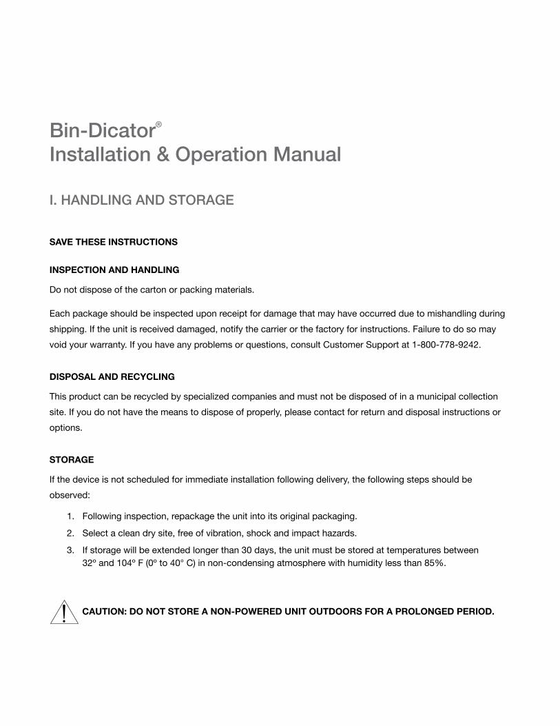
I. HANDLING AND STORAGE
SAVE THESE INSTRUCTIONS
INSPECTION AND HANDLING
Do not dispose of the carton or packing materials.
Each package should be inspected upon receipt for damage that may have occurred due to mishandling during
shipping. If the unit is received damaged, notify the carrier or the factory for instructions. Failure to do so may
void your warranty. If you have any problems or questions, consult Customer Support at 1-800-778-9242.
DISPOSAL AND RECYCLING
This product can be recycled by specialized companies and must not be disposed of in a municipal collection
site. If you do not have the means to dispose of properly, please contact for return and disposal instructions or
options.
STORAGE
If the device is not scheduled for immediate installation following delivery, the following steps should be
observed:
1. Following inspection, repackage the unit into its original packaging.
2. Select a clean dry site, free of vibration, shock and impact hazards.
3. If storage will be extended longer than 30 days, the unit must be stored at temperatures between 32º and 104º F (0º to 40° C) in non-condensing atmosphere with humidity less than 85%.
CAUTION: DO NOT STORE A NON-POWERED UNIT OUTDOORS FOR A PROLONGED PERIOD.
Bin-Dicator®
Installation & Operation Manual

LAA180313 Rev. B2
www.bindicator.com
II. GENERAL SAFETY
AUTHORIZED PERSONNEL
Allinstructionsdescribedinthedocumentmustbeperformedbyauthorizedandqualifiedservicepersonnel
only. Before installing the unit, please read these instructions and familiarize yourself with the requirements and
functions of the device. The required personal protective equipment must always be worn when servicing this
device.
USE
The device is solely intended for use as described in this manual. Reliable operation is ensured only if the
instrumentisusedaccordingtothespecificationsdescribedinthisdocument.Forsafetyandwarranty
reasons,useofaccessoryequipmentnotrecommendedbythemanufacturerormodificationofthisdeviceis
explicitlyforbidden.Allservicingofthisequipmentmustbeperformedbyqualifiedservicepersonnelonly.This
device should be mounted in locations where it will not be subject to tampering by unauthorized personnel.
MISUSE
Improper use or installation of this device may cause the following:
• Personalinjuryorharm
• Applicationspecifichazardssuchasvesseloverfill
• Damagetothedeviceorsystem
If any questions or problems arise during installation of this equipment, please contact Customer Support at
800-778-9242.

3
www.bindicator.com
LAA180313 Rev. B
III. PRODUCT DESCRIPTION
FUNCTION
Bin-Dicator® diaphragm-type level controls were the original electromechanical point level switches and the
firsttoenjoygeneralusageintheindustry.Bin-Dicatorcontrolseliminatebinoverflow,emptybins,clogged
conveyors, choked elevators and the resulting damage and waste.
TheBin-Dicatorcontrolisapressureactuatedswitchforusewithfreeflowingbulkmaterialsatatmospheric
pressures. Actuation of the switch is the result of pressure exerted by the bulk material against the diaphragm
assembly. De-actuation or switch release is a result of the bulk material clearing away from the diaphragm.
FEATURES
Bantam Bin-Dicator
• 5¾”diameter
• 2diaphragmmaterialoptions
• Lightduty
Auto-Bin-Dicator
• 8”diameter
• Castaluminumhousing
• NeopreneorSSdiaphragmmaterial
• Mediumduty
Model ‘A’
• 10¼”diameter
• Explosionproofmodelavail.
• 7diaphragmmaterialoptions
• Heavyduty

LAA180313 Rev. B4
www.bindicator.com
TECHNICAL SPECIFICATIONS
FUNCTIONAL
SwitchStandard 185º F (85º C)
Model-A SPDT: 15 amp resistive @ 250 VAC
Auto-Bin-DicatorStandard SPDT Snap Action Switch (Dry Rated): 15 amp resistive @ 125, 250 or 480 VAC; Pilot duty 375 VA, 125 VAC or 750 VA, 250 VAC
Bantam SPDT: 20 amp resistive @ 250 VAC
Optional SwitchesRatings 250º F (121º C), 800º F (427º C)
Explosion Proof Model-A and Auto-Bin-Dicator
Temperature1.0 of calibrated span (combined linearity, hysteresis, stability) between 0º and 150º F
32º F to185º F (0º to 85º C) standard, Auto and Bantam
Frame Polyester-coated aluminum casting
CoverPolyester-coated aluminum casting (Auto and Bantam)
StandarddurableABSwhiteplastic(Model“A”)
Construction Weather-proof or explosion-proof (Auto)
Diaphragms Neoprene,StainlessSteel(Auto),Aluminum(Bantam),Steelgalvanizedbackplate;Steelpolyesterwasher(Model“A”)
Gasket Rubber(Bantam),Fiber(Model“A”)
Mounting Canbemountedonunderslopesupto45degree(Bantam&Model“A”)
Shipping Weight Aluminum8lbs(Auto&Bantam),Aluminum10lbs(Model“A”)
Pollution Degree 2
Installation Category II
Altitude 6,526 ft (2000 m)
DIAPHRAGM MATERIAL MAx. TEMP PRODUCT WT. Cu./Ft. APPLiCATioNREMARkS
NeopreneRubber(light) 170° F (77° C) 10-40 Highest sensitivity, abrasion resistant
NeopreneRubber(medium) 170° F (77° C) 30-100 Strong, resists abrasion, low temperatures
NeopreneRubber(heavy) 170° F (77° C) 100-350 Strong, resists abrasion, low temperatures
Canvas 200° F (93° C) 10-60 Powders only
Fiberglass 1000° F (538° C) 25-100 Very high temp-see switch temperatures
T-302 SS 800° F (427° C) 30 Min. Auto-Bin-Dicator® only
Silicone Rubber (heavy) 450° F (232º C) 50-150 Extreme low to medium-high temperature
Teflon® Coated Fiberglass (heavy) 400° F (204º C) 50-150 Corrosion resistant, medium-high temperatures
Note:Forhightemperatureapplications,specialswitchesmayberequiredinadditiontoproperdiaphragmselection.Pleaseconsultfactory.
APPROVALS - CONSULT FACTORY FOR SPECIFIC MODEL LISTING
General Purpose: UL, CSAHazardous Location: UL: Class 1, Groups C & D, Class II, Groups E, F, G

5
www.bindicator.com
LAA180313 Rev. B
IV. MECHANICAL INSTALLATION
WARNING: REMOVE POWER FROM THE UNIT BEFORE INSTALLING, REMOVING, OR MAKING ADJUSTMENTS.
BANTAM
GUIDELINES
• Shouldbelocatedatapointwherethematerialwillnormallyreachandactuatethediaphragm,andwhen receding, will completely clear the diaphragm.
• Mountinglocationshouldbeoutofthedirectflowofmaterialintothevessel.
MOUNTING
CAUTION: FOR ALL ANGLES OF MOUNTING, LINE C-D MUST BE IN A VERTICAL PLANE AND LINE A-B MUST BE HORIZONTAL.
1. Lay out 4 and 5 1/8 in. (10 and 13 cm) concentric circles at point where the Bantam Bin-Dicator device is to be mounted.
2. Cut out the 4 in. (10 cm) circle and drill four 9/32 in. holes on the 5 1/8 in. (13 cm) circle.
3. Insert gasket between vessel wall and face of the unit.
4. Fasten to vessel wall with 1/4”mountingbolts.
5. Checkoperationofleversystemandswitch;makefieldadjustmentsasnecessary.
6. Connect conduit and make wiring connections.
7. Replace cover.

LAA180313 Rev. B6
www.bindicator.com
FIELD ADJUSTMENT
1. Check for binding at the pivot points. If binding is occurring, it is likely due to improper mounting. Check to be sure the lever alarm is in a vertical plane and that the mechanism operates freely.
2. Adjustthecounterweight.Forreliableoperationofthecounterweightmustbesufficienttoreturnthediaphragm to normal position when the material completely clears the diaphragm. To adjust the counterweight, loosen the nuts holding the segments in place. Move the weight toward the lever arm to decrease the counterweight. To increase the counterweight, move the weight away from the lever arm. Be sure to lock the counterweight at the desired position.
3. Check switch sensitivity. Switch may be adjusted for more sensitive operation by loosening the top machine screw holding the switch in place and shifting the position of the switch to obtain the desired sensitivity. When making this adjustment, be sure the switch returns to normal when the level plate is slowly lowered by hand.
AUTO-BIN-DICATOR
GUIDELINES
• HighLevelMounting:unitshouldbemountedlowenoughonthevesselwall,sothatmaterialwillnormallycoverthediaphragmandprovidesufficientheadofmaterialbeforethehighlevelsignalisrequired.
• LowLevelMounting:unitshouldbemountedhighenoughonthevesselwall,sothatmaterialinitsnormalflowwillcoverthediaphragmandprovidesufficientheadofmaterialbeforethelowlevelsignalisrequired.
• Mountinglocationshouldbeoutofthedirectflowofmaterialintothevessel.
MOUNTING
1. Mark two concentric circles on the vessel wall at the point where the unit is to be mounted. One circle should be 6 7/8 in. (17 cm) in diameter, the second 77/16 in. (19 cm) in diameter.
2. Cut out the 6 7/8 in. (17 cm) circle.
3. Lay out six (6) equally spaced holes on the 7 7/16 in. (19 cm) circle.
4. Drill or tap 1/4 in. for bolts or cap screws.

7
www.bindicator.com
LAA180313 Rev. B
5. insertthegasketbetweenthevesselwallandtheflangeoftheunitwiththeconduitentryfacingdownward.
6. Fasten the unit to the vessel wall with 1/4 in. bolts or cap screws.
7. Connect conduit and make wiring connections at switch terminals.
8. Screw cover to housing securely to prevent damage or moisture.
9. Check switch operation by manually depressing diaphragm and releasing. The switch should now respond to the pressure.
MODEL ‘A’ (Standard or with Mercury Switch)
GUIDELINES
• Shouldbelocatedatapointwherethematerialinitsnormalflowwillreachandmovethediaphragm,and when receding, will completely clear the diaphragm.
• Mountinglocationshouldbeoutofthedirectflowofmaterialintothevessel.
• ifthematerialisoflighterdensityoriftheunitistobemountedontheunder-slope,thecounterweightmust be reduced to provide sensitive operation of the unit.
• ifthematerialisofheavierdensityoriftheunitismountedontheunder-slope,thecounterweightmustbe increased to return the diaphragm to normal as the material clears the diaphragm.
MOUNTING
CAUTION: WHEN MOUNTING LINE C-D MUST BE ON A VERTICAL PLANE AND LINE A-B MUST BE HORIZONTAL.
1. Mark two concentric circles on the vessel wall at the point where the unit is to be mounted. One circle should be 8 in. (20 cm) in diameter, the second 93/8 in. (24 cm) in diameter.
2. Cut out the 8 in. (20 cm) circle.
3. Lay out six (6) equally spaced holes on the 93/8 in. (24 cm) circle.
4. Drill or tap 1/4 in. bolts or cap screws.
5. insertthegasketbetweenthevesselwallandtheflangeoftheunitwiththeconduitfacingdown.
6. Fasten the unit to the vessel wall with 1/4 in. bolts or cap screws.

LAA180313 Rev. B8
www.bindicator.com
7. Checkoperationofleversystemandswitch;makefieldadjustmentsasnecessary.
8. Connect conduit and make wiring connections.
9. Replace cover.
FIELD ADJUSTMENT
1. Check for binding at the pivot points. If binding is occurring, it is likely due to improper mounting. Check to be sure the lever alarm is in a vertical plane and that the mechanism operates freely.
2. Adjustthecounterweight.Forreliableoperationofthecounterweightmustbesufficienttoreturnthediaphragm to normal position when the material completely clears the diaphragm. To adjust the counterweight, loosen the nuts holding the segments in place. Ad or remove counterweight washers to adjust.
3. Check switch sensitivity. Switch may be adjusted for more sensitive operation by loosening the top machine screw holding the switch in place and shifting the position of the switch to obtain the desired sensitivity. When making this adjustment, be sure the switch returns to normal when the level plate is slowly lowered by hand.
Figure 1. General Component Layout
Lever PlatePivot Points
Counter WeightLevel Actuator
Micro Switch
Pivot Points
Level ActuatorCounter Weight
Lever Plate
Pivot Points
Mecury Switch
Pivot Points
Counter Weight
Figure 2. Mercury Switch Component Layout

9
www.bindicator.com
LAA180313 Rev. B
V. ELECTRICAL INSTALLATION
WARNING: VERY HIGH VOLTAGE IS PRESENT. REMOVE POWER FROM THE UNIT BEFORE
INSTALLING, REMOVING, OR MAKING ADJUSTMENTS
GENERAL SAFETY
When using electrical equipment, you should always follow basic safety precautions, including the following:
• Theinstallationandwiringofthisproductmustcomplywithallnational,federal,state,municipal,andlocal codes that apply.
• Properlygroundtheenclosuretoanadequateearthground.
• Do not modify any factory wiring. Connections should only be made to the terminals described in this section.
• Allconnectionstotheunitmustuseconductorswithaninsulationratingof300Vminimum,ratedfor221ºF(105ºC),aminimumflammabilityratingofVW-1,andbeofappropriategaugeforthevoltageandcurrentrequired(seespecifications).
• Donotallowmoisturetoentertheelectronicsenclosure.Conduitshouldslopedownwardfromtheunit
housing. Install drip loops and seal conduit with silicone rubber product.
DISCONNECT REQUIREMENTS FOR PERMANENTLY INSTALLED EQUIPMENT
A dedicated disconnecting device (circuit breaker) must be provided for the proper installation of the unit. If
independent circuits are used for power input and outputs, individual disconnects are required.
Disconnects must meet the following requirements:
• Locatedincloseproximitytothedevice
• Easilyaccessibletotheoperator
• Appropriatelymarkedasthedisconnectforthedeviceandassociatedcircuit
• Sizedappropriatelytotherequirementsoftheprotectedcircuit(Seespecifications)
PROTECTIVE EARTH GROUND
To eliminate shock hazards in the unlikely event of an internal insulation breakdown, the unit is provided with a
“protectiveearth”( ) lead which must be connected to earth ground. In addition, the input power ground
leadmustbeconnectedtothe“protectiveearth”( ) terminal provided. Wire sizes must be selected such
that it can safely carry the sum total of all circuits’ maximum amperage.
WIRING
Common
Normallyopen(No)
NormallyClosed(NC)

LAA180313 Rev. B10
www.bindicator.com
VI. MAINTENANCE
PREVENTIVE MAINTENANCE
Semi-annual or annual inspection of the diaphragm, vent and switch circuit is recommended.
RECOMMENDED SPARE PARTS
BANTAM BIN-DICATORLAB110700 A-BB-3 Lever Arm Assembly
LAB121360 BB-2 Cover
LAB121410 BB-6 Aluminum Diaphragm Retaining Washer
LAB121420 BB-6A Stainless Steel Diaphragm Retaining Washer
LAB121430 BB-9 NeopreneDiaphragm
LAB121510 BB-9H Teflon®-CoatedNeopreneDiaphragm
LAB121530 BB-15 Diaphragm Back Plate
LAB121580 BB-5 Brass Pivot Rod
LAB122138 BB-3 Brass Lever Arm
LAB130940 BB-7 Rubber Mounting Gasket
LAB130950 BB-7A Rubber Cover Gasket
LAB130960 BB-8 Counterweight Segment, Lead, 1 oz
LAB130970 Micro Switch, 185° F (85° C), Marked BA-2RV-191-A2
LAB130980 Micro Switch, 250° F (121° C)
AUTO-BIN-DICATORLAD110750 A-D-8A Switch Assembly w/ Bracket, Cam, and Barriers; 185° F (85 C)
LAD110751 A-D-8B Switch Assembly w/ Bracket, Cam, and Barriers; 250 F (121 C)
LAD110752 A-D-8C 00 Switch Assembly w/ Bracket, Cam, and Barriers; 800 F (427 C)
LAD121590 AB-4 Diaphragm Back Plate
LAD121600 AB-5 Aluminum Diaphragm Retaining Washer
LAD121610 AB-6 Stainless Steel Diaphragm
LAD121620 AB-6A NeopreneDiaphragm
LAD122004 AB-5SS Stainless Steel Diaphragm Retaining Washer
LAD131030 AB-8 Perimeter Springs (Behind Diaphragm Back Plate)
LAD131040 D-8A Micro Switch Marked BA-2RB35-A2, 185° F (85° C)
LAD131050 D-8B Micro Switch, 250° F (121° C)
LAD131060 D-8C Micro Switch, 800° F (427° C)
LAD131090 AB-10 Mounting Gasket
LAG110800 G-6E Cam Assembly
LAG121700 G-3 Cover
LAG121760 G-7A Push Rod

11
www.bindicator.com
LAA180313 Rev. B
MODEL ALAA110550 A-115-A Canvas Diaphragm Assembly
LAA110560 A-11 Fiberglass Diaphragm Assembly, 0.010 in. (0.254 mm)
LAA110570 A-115-C LightNeopreneDiaphragmAssembly,0.013in.(0.330mm)
LAA110580 A-115-D MediumNeopreneDiaphragmAssembly,0.025in.(0.635mm)
LAA110590 A-115-E HeavyNeopreneDiaphragmAssembly
LAA110610 A-115-G Heavy Silicone Diaphragm Assembly
LAA110630 A-115-J HeavyTeflon®-Coated Fiberglass Diaphragm Assembly
LAA110670 A-AA18 (2) 119-A Switches Mounted in Brackets
LAA110790 A-116A Mercury Switch (G-10Z) and Mounting Clip
LAA120980 AA-5A Lever Plate (Micro/Mercury Switch)
LAA120990 AA-5B Lever Plate (Micro Switch) Model, Underslope Mounting
LAA121010 AA-9A Cover for Explosionproof Model A Bin-Dicator
LAA121040 AA-10 Steel Diaphragm Retaining Washer
LAA121050 AA-10A Stainless Steel Diaphragm Retaining Washer
LAA121090 AA-13B Single/Double Micro Switch Bracket, Aluminum (2 Required)
LAA121110 AA-13D High Temperature Micro Switch Bracket (1 Required)
LAA121130 AA-14 Steel Diaphragm Back Plate
LAA122120 AA-2 Brass Pivot Rod
LAA122121 AA-3 Brass Diaphragm Push Rod
LAA130591 AA-9 General Purpose Cover, Plastic, Model A
LAA130592 General Purpose Cover, Minlon®, Model A
LAA130730 AA-7 Counterweight Segment, Lead, 1 oz
LAA130770 AA-11 Cover Mounting Gasket
LAA130780 AA-11 klingerMountingGasketforHighTemperatureSwitch
LAA130800 117 Mercury Switch (G-10Z) Mounting Clip
LAA130810 118 2-Pole Terminal Block
LAA130820 119-A Micro Switch, 185º F (85º C)
LAA130830 119-B Micro Switch, 250º F (121º C)
LAA130840 119-C 00 Micro Switch, 800º F (427º C)
LAA130850 122-A 0 Ex-AR Explosionproof Micro Switch, SP/DT, 185º F (85º C)
LAA130860 122-B 0 Ex-DAR Explosionproof Micro Switch, DP/DT, 185º F (85º C)
LUA030820 4107 BrassExternalCapNutforAA-3BrassRod
LUA030830 4107A StainlessSteelExternalCapNutforAA-3BrassRod

LAA180313 Rev. B12
www.bindicator.com
VI. DIMENSIONAL DRAWINGS
Bantam Bin-Dicator
Auto-Bin-Dicator
Model ‘A’

13
www.bindicator.com
LAA180313 Rev. B
Notes:

LAA180313 Rev. B14
www.bindicator.com
Notes:

15
www.bindicator.com
LAA180313 Rev. B

150 Venture Boulevard Spartanburg, SC 29306Tel: (800) 778-9242Fax: (864) [email protected]
2013 All rights reserved.All data subject to change without notice.
LAA180313 Rev. B