BIM for the Construction Industry - Luleå University of ...staff.marsan/P7006B/Literature/Eastman...
36
CHAPTER 6 BIM for the Construction Industry 6.0 EXECUTIVE SUMMARY U tilizing BIM technology has major advantages for construction that save time and money. An accurate building model benefits all members of the project team. It allows for a smoother and better planned construction process that saves time and money and reduces the potential for errors and conflicts. This chapter explains how a contractor can obtain these benefits and what changes to construction processes are desirable. Perhaps the most important point is that contractors must push for early involvement in construction projects, or seek out owners that require early participation. Contractors and owners should also include subcontractors and fabricators in their BIM efforts. The traditional design-bid-build approach lim- its the contractor’s ability to contribute their knowledge to the project during the design phase, when they can add significant value. While some of the potential value of a contractor ’s knowledge is lost after the design phase is complete, significant benefits to the contractor and the project team can still be realized by using a building model to support a variety of con- struction work processes. These benefits can ideally be achieved by developing a model in-house with the collaboration of subcontractors and fabricators; having a consultant develop a model is also possible. The level of detail of the information in a building model depends on what functions it will be used for. For example, for accurate cost estimating, the model must be sufficiently detailed to provide the material quantities needed for cost evaluation. For 4D CAD schedule analysis, a less detailed model is adequate, 207 BIM Handbook: A Guide to Building InformationModeling for Owners, Managers,Designers, Engineers, and Contractors. Chuck Eastman, Paul Teicholz, Rafael Sacks and Kathleen Liston Copyright © 2008 John Wiley & Sons, Inc.
Transcript of BIM for the Construction Industry - Luleå University of ...staff.marsan/P7006B/Literature/Eastman...

C H A P T E R6
BIM for the Construction Industry
6.0 EXECUTIVE SUMMARY
Utilizing BIM technology has major advantages for construction that save time and money. An accurate building model benefi ts all members of the
project team. It allows for a smoother and better planned construction process that saves time and money and reduces the potential for errors and confl icts. This chapter explains how a contractor can obtain these benefi ts and what changes to construction processes are desirable.
Perhaps the most important point is that contractors must push for early involvement in construction projects, or seek out owners that require early participation. Contractors and owners should also include subcontractors and fabricators in their BIM efforts. The traditional design - bid - build approach lim-its the contractor ’ s ability to contribute their knowledge to the project during the design phase, when they can add signifi cant value.
While some of the potential value of a contractor ’ s knowledge is lost after the design phase is complete, signifi cant benefi ts to the contractor and the project team can still be realized by using a building model to support a variety of con-struction work processes. These benefi ts can ideally be achieved by developing a model in - house with the collaboration of subcontractors and fabricators; having a consultant develop a model is also possible.
The level of detail of the information in a building model depends on what functions it will be used for. For example, for accurate cost estimating, the model must be suffi ciently detailed to provide the material quantities needed for cost evaluation. For 4D CAD schedule analysis, a less detailed model is adequate,
207
c06.indd 207c06.indd 207 1/16/08 11:38:32 AM1/16/08 11:38:32 AM
BIM Handbook: A Guide to Building Information Modeling for Owners, Managers, Designers, Engineers, and Contractors.Chuck Eastman, Paul Teicholz, Rafael Sacks and Kathleen Liston Copyright © 2008 John Wiley & Sons, Inc.
208 Chapter 6 BIM for the Construction Industry
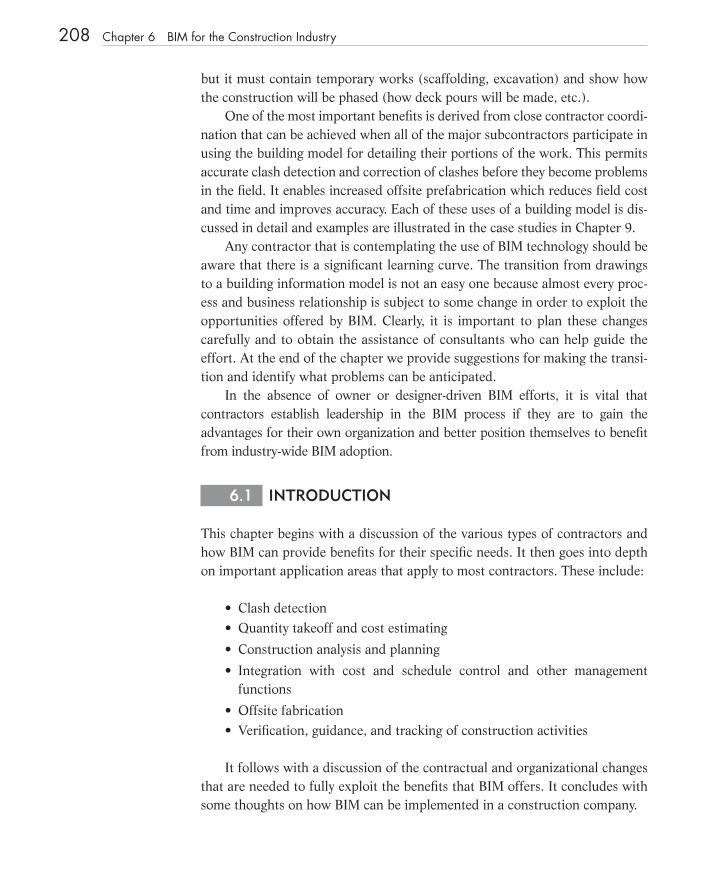
but it must contain temporary works (scaffolding, excavation) and show how the construction will be phased (how deck pours will be made, etc.).
One of the most important benefi ts is derived from close contractor coordi-nation that can be achieved when all of the major subcontractors participate in using the building model for detailing their portions of the work. This permits accurate clash detection and correction of clashes before they become problems in the fi eld. It enables increased offsite prefabrication which reduces fi eld cost and time and improves accuracy. Each of these uses of a building model is dis-cussed in detail and examples are illustrated in the case studies in Chapter 9 .
Any contractor that is contemplating the use of BIM technology should be aware that there is a signifi cant learning curve. The transition from drawings to a building information model is not an easy one because almost every proc-ess and business relationship is subject to some change in order to exploit the opportunities offered by BIM. Clearly, it is important to plan these changes carefully and to obtain the assistance of consultants who can help guide the effort. At the end of the chapter we provide suggestions for making the transi-tion and identify what problems can be anticipated.
In the absence of owner or designer - driven BIM efforts, it is vital that contractors establish leadership in the BIM process if they are to gain the advantages for their own organization and better position themselves to benefi t from industry - wide BIM adoption.
6.1 INTRODUCTION
This chapter begins with a discussion of the various types of contractors and how BIM can provide benefi ts for their specifi c needs. It then goes into depth on important application areas that apply to most contractors. These include:
Clash detection Quantity takeoff and cost estimating
Construction analysis and planning
Integration with cost and schedule control and other management functions
Offsite fabrication Verifi cation, guidance, and tracking of construction activities
It follows with a discussion of the contractual and organizational changes that are needed to fully exploit the benefi ts that BIM offers. It concludes with some thoughts on how BIM can be implemented in a construction company.
••
•
•
••
c06.indd 208c06.indd 208 1/16/08 11:38:33 AM1/16/08 11:38:33 AM

6.2 TYPES OF CONSTRUCTION FIRMS
There is a tremendous range of construction companies, from large companies that operate in many countries and offer a wide range of services to small com-panies that have individual owners who work on one project at a time and provide a highly specialized service. There are far more of the latter (small - scale companies) than the former, and they perform a surprisingly large percentage of the total construction volume. Data for 2004 is shown in Figure 6 - 1 . It shows that a large percentage of fi rms were composed of just 1 to 19 people (91.6%), but a majority of construction employees worked in fi rms larger than 19 people (61.6%). A very small percentage of fi rms (0.12%) had over 500 workers, and they employed 13.6% of the workforce. Average fi rm size was 9 employees.
When we look at the building industry, the range of contractors is also very large in terms of the services they offer. The bulk of the industry consists of contractors who start with a successful bid, self - perform some of the work, and hire subcontractors for specialized services. Some contractors limit their service to managing the construction process. They hire subcontractors for all construction work. At the other end of the spectrum are design - build fi rms that take responsibility for both the design and construction processes but subcontract the bulk of the construction work. Almost all contractors end their responsibilities when construction is complete, but there are some that offer services in the turnover and management phases of the fi nished building
6.2 Types of Construction Firms 209
FIGURE 6 - 1 Distribution of 751,098 construction fi rms and total employees by size of fi rm for 2004. Source: US Census Bureau, NAICS 23 – Construction.
Percentage of Firms and Employees by Firm Size(Based on 2004 U.S. Census Data)
0
500,000
1,000,000
1,500,000
2,000,000
2,500,000
1to4
5to9
10to19
20to99
100to
499
500to
749
750to
999
1,000to
1,499
1,500to
2,499
2,500to
4,999
5,000to
9,999
10,000+
Firm Size
0
50,000
100,000
150,000
200,000
250,000
300,000
350,000
400,000
Num
ber of Firms
Num
ber
of E
mpl
oyee
s
Employees Firms
c06.indd 209c06.indd 209 1/16/08 11:38:34 AM1/16/08 11:38:34 AM
210 Chapter 6 BIM for the Construction Industry
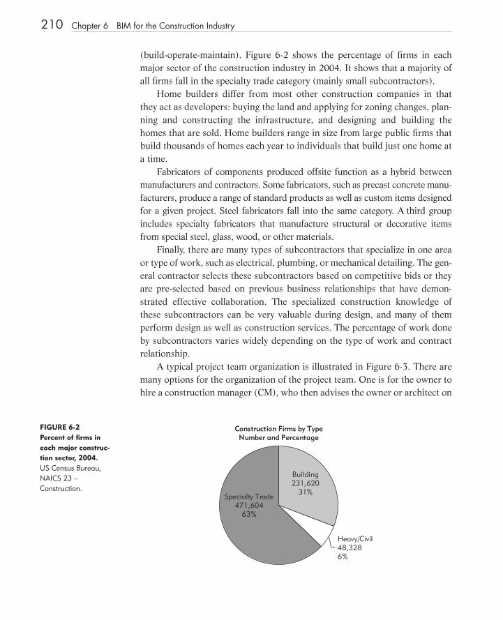
(build - operate - maintain). Figure 6 - 2 shows the percentage of fi rms in each major sector of the construction industry in 2004. It shows that a majority of all fi rms fall in the specialty trade category (mainly small subcontractors).
Home builders differ from most other construction companies in that they act as developers: buying the land and applying for zoning changes, plan-ning and constructing the infrastructure, and designing and building the homes that are sold. Home builders range in size from large public fi rms that build thousands of homes each year to individuals that build just one home at a time.
Fabricators of components produced offsite function as a hybrid between manufacturers and contractors. Some fabricators, such as precast concrete manu-facturers, produce a range of standard products as well as custom items designed for a given project. Steel fabricators fall into the same category. A third group includes specialty fabricators that manufacture structural or decorative items from special steel, glass, wood, or other materials.
Finally, there are many types of subcontractors that specialize in one area or type of work, such as electrical, plumbing, or mechanical detailing. The gen-eral contractor selects these subcontractors based on competitive bids or they are pre - selected based on previous business relationships that have demon-strated effective collaboration. The specialized construction knowledge of these subcontractors can be very valuable during design, and many of them perform design as well as construction services. The percentage of work done by subcontractors varies widely depending on the type of work and contract relationship.
A typical project team organization is illustrated in Figure 6 - 3 . There are many options for the organization of the project team. One is for the owner to hire a construction manager (CM), who then advises the owner or architect on
Construction Firms by TypeNumber and Percentage
Heavy/Civil48,3286%
Building231,620
31%Specialty Trade
471,60463%
FIGURE 6 - 2 Percent of fi rms in each major construc-tion sector, 2004. US Census Bureau, NAICS 23 – Construction.
c06.indd 210c06.indd 210 1/16/08 11:38:35 AM1/16/08 11:38:35 AM
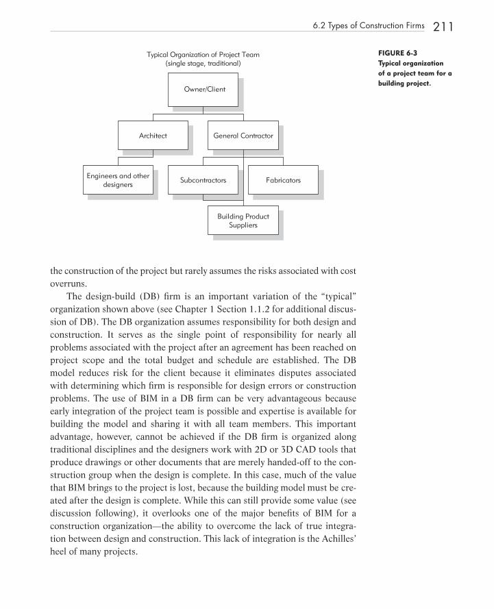
the construction of the project but rarely assumes the risks associated with cost overruns.
The design - build (DB) fi rm is an important variation of the “ typical ” organization shown above (see Chapter 1 Section 1.1.2 for additional discus-sion of DB). The DB organization assumes responsibility for both design and construction. It serves as the single point of responsibility for nearly all problems associated with the project after an agreement has been reached on project scope and the total budget and schedule are established. The DB model reduces risk for the client because it eliminates disputes associated with determining which fi rm is responsible for design errors or construction problems. The use of BIM in a DB fi rm can be very advantageous because early integration of the project team is possible and expertise is available for building the model and sharing it with all team members. This important advantage, however, cannot be achieved if the DB fi rm is organized along traditional disciplines and the designers work with 2D or 3D CAD tools that produce drawings or other documents that are merely handed - off to the con-struction group when the design is complete. In this case, much of the value that BIM brings to the project is lost, because the building model must be cre-ated after the design is complete. While this can still provide some value (see discussion following), it overlooks one of the major benefi ts of BIM for a construction organization — the ability to overcome the lack of true integra-tion between design and construction. This lack of integration is the Achilles ’ heel of many projects.
6.2 Types of Construction Firms 211
FIGURE 6 - 3 Typical organization of a project team for a building project.
Owner/Client
Architect
Typical Organization of Project Team(single stage, traditional)
General Contractor
Engineers and otherdesigners Subcontractors Fabricators
Building ProductSuppliers
c06.indd 211c06.indd 211 1/16/08 11:38:35 AM1/16/08 11:38:35 AM

6.3 INFORMATION CONTRACTORS WANT FROM BIM
Given the diversity of contractor types described above, it is not surprising that there is a wide range of processes and tools currently in use across the industry. Larger fi rms typically use computer - based systems for almost all of their key work processes, including: estimating, construction planning and scheduling, cost con-trol, accounting, procurement, supplier and vendor management, marketing, etc. For tasks related to the design, such as estimating, coordination and scheduling, paper plans and specifi cations are the typical starting point, even if the architect used 2D or 3D CAD systems for the design. These require contractors to manually perform quantity takeoffs to produce an accurate estimate and schedule, which is a time - consuming, tedious, error - prone and expensive process. For this reason, cost estimates, coordinated drawings, and detailed schedules are often not per-formed until late in the design process.
Fortunately, this methodology is beginning to change, as contractors are recognizing the value of BIM for construction management. By using BIM tools, architects are potentially able to provide models that contractors can use for estimating, coordination, construction planning, fabrication, procurement, and other functions. At a minimum, the contractor can use this model to quickly add detailed information. To permit these capabilities, a building model would opti-mally provide contractors with the following types of information :
Detailed building information contained in an accurate 3D model that provides graphic views of a building ’ s components comparable to that shown in typical construction drawings and with the ability to extract quantity and component property information. Temporary components to represent equipment, formwork and other temporary components that are critical to the sequencing and planning of the project.
Specifi cation information associated with each building component with links to textual specifi cations for every component that the contrac-tor must purchase or construct.
Analysis data related to performance levels and project requirements such as structural loads, connection reactions and maximum expected moments and shear, heating and cooling loads for tonnage of HVAC systems, targeted luminance levels, etc. This data is for fabrication and MEP detailing. Design and construction status of each component to track and validate the progress of components relative to design, procurement,
•
•
•
•
•
212 Chapter 6 BIM for the Construction Industry
c06.indd 212c06.indd 212 1/16/08 11:38:36 AM1/16/08 11:38:36 AM
installation, and testing (if relevant). This data is added to the model by the contractor.
No BIM tool today comes close to satisfying this list of requirements, but this list serves to identify the information needs for future BIM implementa-tions. Today, most BIM tools support the creation of information in the fi rst and second items in the list.
An accurate, computable, and relatively complete building model that includes the above information is needed to support critical contractor work processes for estimating, coordinating trades and building systems, fabricating components offsite, and construction planning. It is important to note that each new work process often requires that the contractor add information to the model, since the architect or engineer would not traditionally include means and methods information such as equipment or production rates, which are critical for estimating, scheduling and procurement. Contractors use the building model to provide a base structure to extract information and will add construction - specifi c information as - needed to support various construction work processes.
Additionally, if the scope of work for the contractor includes turnover or operations of the facility, links between BIM components and owner control systems, such as maintenance or facility management, will facilitate the hand-over process to the owner at the end of the project. The building model needs to support representation of information related to all of these processes.
6.4 PROCESSES TO DEVELOP A CONTRACTOR BUILDING INFORMATION MODEL
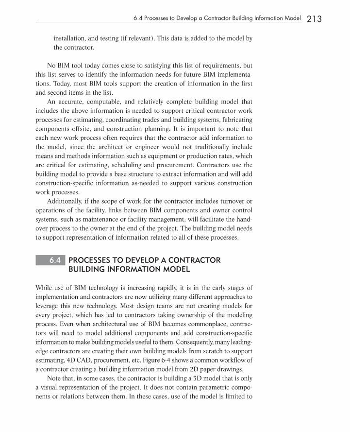
While use of BIM technology is increasing rapidly, it is in the early stages of implementation and contractors are now utilizing many different approaches to leverage this new technology. Most design teams are not creating models for every project, which has led to contractors taking ownership of the modeling process. Even when architectural use of BIM becomes commonplace, contrac-tors will need to model additional components and add construction - specifi c information to make building models useful to them. Consequently, many leading - edge contractors are creating their own building models from scratch to support estimating, 4D CAD, procurement, etc. Figure 6 - 4 shows a common workfl ow of a contractor creating a building information model from 2D paper drawings.
Note that, in some cases, the contractor is building a 3D model that is only a visual representation of the project. It does not contain parametric compo-nents or relations between them. In these cases, use of the model is limited to
6.4 Processes to Develop a Contractor Building Information Model 213
c06.indd 213c06.indd 213 1/16/08 11:38:36 AM1/16/08 11:38:36 AM
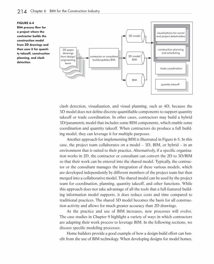
clash detection, visualization, and visual planning, such as 4D, because the 3D model does not defi ne discrete quantifi able components to support quantity takeoff or trade coordination. In other cases, contractors may build a hybrid 3D/parametric model that includes some BIM components, which enable some coordination and quantity takeoff. When contractors do produce a full build-ing model, they can leverage it for multiple purposes.
Another approach for implementing BIM is illustrated in Figure 6 - 5 . In this case, the project team collaborates on a model – 3D, BIM, or hybrid – in an environment that is suited to their practice. Alternatively, if a specifi c organiza-tion works in 2D, the contractor or consultant can convert the 2D to 3D/BIM so that their work can be entered into the shared model. Typically, the contrac-tor or the consultant manages the integration of these various models, which are developed independently by different members of the project team but then merged into a collaborative model. The shared model can be used by the project team for coordination, planning, quantity takeoff, and other functions. While this approach does not take advantage of all the tools that a full - featured build-ing information model supports, it does reduce costs and time compared to traditional practices. The shared 3D model becomes the basis for all construc-tion activity and allows for much greater accuracy than 2D drawings.
As the practice and use of BIM increases, new processes will evolve. The case studies in Chapter 9 highlight a variety of ways in which contractors are adapting their work process to leverage BIM. In the following sections, we discuss specifi c modeling processes.
Home builders provide a good example of how a design - build effort can ben-efi t from the use of BIM technology. When developing designs for model homes,
214 Chapter 6 BIM for the Construction Industry
FIGURE 6 - 4 BIM process fl ow for a project where the contractor builds the construction model from 2 D drawings and then uses it for quanti-ty takeoff, construction planning, and clash detection.
contractor or consultantbuilds/updates BIM
2D paperdrawings
from design/engineering
team
visualizations for ownerand project stakeholders
quantity takeoff
construction planningand scheduling
trade coordination
3D model
3D model/BIM
BIM
c06.indd 214c06.indd 214 1/16/08 11:38:37 AM1/16/08 11:38:37 AM

a building information model can provide rapid feedback on the quantity and cost implications of a design change. When a buyer requests design modifi cations to a model home, this capability can provide fast visual and cost feedback and allow the prospective buyer to quickly reach an agreement with the builder. This kind of rapid response to clients ’ needs is of great value, especially for construction companies that provide customized building options based on systematic meth-ods of construction † .
4D CAD tools allow the contractor to simulate and evaluate the planned construction sequence and share it with others in the project team. Objects in the building model should be grouped according to the phases of construction and linked to appropriate activities in a project schedule. For example, if a con-crete deck will be placed in three pours, then the deck must be detailed into three sections so that this sequence can be planned and illustrated. This applies to all objects needed for these three pours: concrete, steel, embeds, etc. In addition, the excavation areas and temporary structures such as scaffolding and lay - down areas should be included in the model. This is a key reason why con-tractor knowledge is benefi cial when defi ning a building model. If the model is built by the architect or the contractor while the building is still being designed, the contractor can provide rapid feedback regarding constructability, sequenc-ing, and estimated construction cost. Early integration of this information is of great benefi t to the architect and owner.
6.4 Processes to Develop a Contractor Building Information Model 215
contractor orconsultant
builds/updates model
2D paperdrawings
from design/engineering
team
visualizations forowner and project
stakeholders
quantity takeoff
constructionplanning
and scheduling
trade coordination
shared 3D/BIM model
3D/BIMmodels fromproject team
contractor orconsultantintegratesmodels
FIGURE 6 - 5 Process fl ow for a project, where the architect and other designers and sub contractors use 3 D modeling tools (or have a consultant develop a 3 D model from 2 D drawings) and contribute to a shared 3 D model.
† Three examples are the high - tech offi ce buildings provided by the Beck Group, small scale steel buildings provided by < < http://www.butlermfg.com/steel_bld_ctr/ > > or < < http://www. steelbuildings.com > > and precast parking structures designed, manufactured and built by Finfrock. Each of these companies has developed sophisticated BIM applications integrated with cost - estimating systems. The trend they represent, exploiting BIM to provide a competitive advantage by providing customized but yet ‘ off - the - shelf ’ buildings, is detailed in Chapter 7 .
c06.indd 215c06.indd 215 1/16/08 11:38:37 AM1/16/08 11:38:37 AM

216 Chapter 6 BIM for the Construction Industry
6.5 REDUCTION OF DESIGN ERRORS USING CLASH DETECTION
A critical work process for any contractor is trade and system coordination. Today, most clash detection is performed manually by overlaying individual system drawings on a light table to identify potential confl icts. Similarly, con-tractors use traditional 2D - CAD tools to overlay CAD layers to visually and manually identify potential confl icts. These manual approaches are slow, costly, prone to error, and depend on the use of up - to - date drawings. To overcome these problems, some organizations use custom - written applications for automatically detecting clashes between drawing entities on different layers. Automatic detection of confl icts is an excellent method for identifying design errors, where objects either occupy the same space (a hard clash) or are so close (a soft clash) that there is insuffi cient space for access, insulation, safety, etc. In some publications, the term ‘ clearance clash ’ is used instead of ‘ soft clash ’ . The terms are synonymous.
BIM - based clash detection provides many advantages over traditional 2D coordination methods like overlays on a light table or automated 3D checks. Use of a light table is time consuming, error prone and requires that all drawings be current. 3D clash detection relies on 3D geometry models for identifying geometric entities often return a large number of meaningless clashes. Second, if the 3D geometries are not solids. the clash detection tool cannot detect clashes between objects within other objects. It can only detect clashes between sur-faces. Furthermore, qualifi cation of clashes into meaningful categories for the contractor is greatly inhibited due to lack of semantic information embedded in the 3D geometry models. A clash between surfaces could be a wall abutting a wall or a pipe running through a wall. The contractor has to verify and review each of these potential clashes.
In contrast, BIM - based clash detection tools allow automatic geometry - based clash detection to be combined with semantic and rule - based clash analysis for identifying qualifi ed and structured clashes. BIM - based clash detection tools allow contractors to selectively check clashes between specifi ed systems, such as checking for clashes between mechanical and structural systems, because each component in the model is associated with a specifi c type of system. Conse-quently, the clash detection process can be performed at any level of detail and across any number of building systems and trades. A BIM - based clash detection system can also utilize these component classifi cations to more readily perform soft clash analyses. For example, the contractor can search for conditions in which the clearance or space between mechanical components and the sub - fl oor is less than two feet. These types of clash detection analyses are only possible with well - defi ned and structured building models.
c06.indd 216c06.indd 216 1/16/08 11:38:38 AM1/16/08 11:38:38 AM

Regardless of the model ’ s accuracy, the contractor must ensure that the building is modeled with an appropriate level of detail. It must have suffi cient details for piping, ducts, structural steel and attachments, and other compo-nents, so that clashes can be accurately detected. If the detailing is inaccurate, a signifi cant number of problems will not be found until the building is con-structed, at which time they could be costly and time consuming to resolve. Proper detailing of the model by subcontractors or other project team members responsible for the design of these systems is required. These subcontractors need to participate in the model development process as early as possible. Ide-ally, resolution would take place in a common project site offi ce, where a large monitor can be used to display each problem area and each discipline can con-tribute their expertise to the solution. Agreed upon changes can then be entered into the appropriate design model prior to the next clash detection cycle. Figure 6 - 6 shows a snapshot of two employees from the contractor and subcon-tractor using a building information model to support MEP coordination. This was done in a trailer at the job site. The case study of the Camino Group Medical Building in Chapter 9 is a good example of early subcontractor participation in detailing a 3D model used for clash detection and other functions.
There are two predominant types of clash detection technologies available in the marketplace: 1) clash detection with BIM design tools and 2) BIM integration tools that perform clash detection. All major BIM design tools include some
FIGURE 6 - 6 Snapshot of contractors and subcontractor using a building information model to support MEP coordination. Courtesy of Swinerton, Inc.
6.5 Reduction of Design Errors Using Clash Detection 217
c06.indd 217c06.indd 217 1/16/08 11:38:38 AM1/16/08 11:38:38 AM

218 Chapter 6 BIM for the Construction Industry
clash detection features that allow the designer to check for clashes during the design phase. But the contractor often needs to integrate these models and may or may not be able to do so successfully within the BIM authoring tool due to poor interoperability or the number and complexity of objects.
The second class of clash detection technologies can be found in BIM inte-gration tools. These tools allow users to import 3D models from a wide variety of modeling applications and visualize the integrated model. Examples of this are Navisworks ’ JetStream package (Navisworks 2007) and Solibri Model Checker (Solibri 2007). The clash detection analyses that these tools provide tend to be more sophisticated, and they are capable of identifying more types of soft and hard clashes. The drawback is that identifi ed clashes cannot be fi xed immediately because the integrated model is not directly associated with the original model. In other words, the information fl ow is one - way and not bi - directional. An exception to this statement is the Solibri Model Checker and Issue Locator which do have the ability to provide feedback in the originating building model for Architectural Desktop (from Autodesk) and ArchiCAD (from Graphisoft). These changes must also be introduced into the originating systems or upstream modeling tools. Then new fi les are generated when the integrated model is updated and a new clash detection analysis is performed. The updating process can cause errors and delays that must be further coordi-nated through careful fi le management among the project team.
6.6 QUANTITY TAKEOFF AND COST ESTIMATING
There are many types of estimates that can be developed during the design process. These range from approximate values early in the design to more pre-cise values after the design is complete. Clearly, it is undesirable to wait until the end of the design phase to develop a cost estimate. If the project is over budget after the design is complete, there are only two options: cancel the project or apply value engineering to cut costs and possibly quality. As the design progresses, interim estimates help to identify problems early so that alternatives can be considered. This process allows the designer and owner to make more informed decisions, resulting in higher quality construction that meets cost con-straints. Just as signifi cant, using a BIM approach can reduce the time needed to achieve a high quality building by improving design and construction collabora-tion and accuracy.
During the early design phase, the only quantities available for estimating are those associated with areas and volumes, such as types of space, perimeter
c06.indd 218c06.indd 218 1/16/08 11:38:41 AM1/16/08 11:38:41 AM

lengths, etc. These quantities might be adequate for what is called a parametric cost estimate , which is calculated based on major building parameters. The parameters used depend on the building type, e.g., number of parking spaces and fl oors for a parking garage, number and area of each type of commercial space, number of fl oors, quality level of materials for a commercial building, location of building, etc. Unfortunately these quantities are not generally avail-able in early design packages (such as SketchUp), because they do not defi ne object types, such as those created by a BIM package. Therefore, it is important to move the early design model into BIM software to allow for quantity extrac-tions and approximate cost estimates. An example of this type of system is the DProfi ler modeling and estimating system from Beck Technology (see addi-tional description of this system in Chapter 4 and the Hillwood Commercial Project case study in Chapter 9 ).
As the design matures, it is possible to rapidly extract more detailed spatial and material quantities directly from the building model. All BIM tools provide capabilities for extracting counts of components, area and volume of spaces, material quantities, and to report these in various schedules. These quantities are more than adequate for producing approximate cost estimates. For more accurate cost estimates prepared by contractors, problems may arise when the defi nitions of components (typically assemblies of parts) are not properly defi ned and are not capable of extracting the quantities needed for cost esti-mating. For example, BIM software might provide the linear feet of concrete footings but not the quantity of reinforcing steel embedded in the concrete; or the area of interior partition walls but not the quantity of studs in the walls. These are problems that can be addressed, but the approach depends on the specifi c BIM tool and associated estimating system.
It should be noted that while building models provide adequate measure-ments for quantity takeoffs, they are not a replacement for estimating. Estimators perform a critical role in the building process far beyond that of extracting counts and measurements. The process of estimating involves assessing conditions in the project that impact cost, such as unusual wall conditions, unique assemblies, and diffi cult access conditions. Automatic identifi cation of these conditions by any BIM tool is not yet feasible. Estimators should consider using BIM technol-ogy to facilitate the laborious task of quantity takeoff and to quickly visualize, identify, and assess conditions, and provide more time to optimize prices from subcontractors and suppliers. A detailed building model is a risk - mitigation tool for estimators that can signifi cantly reduce bid costs, because it reduces the uncertainty associated with material quantities. The One Island East Offi ce Tower case study in Chapter 9 is an excellent example of this.
6.6 Quantity Takeoff and Cost Estimating 219
c06.indd 219c06.indd 219 1/16/08 11:38:42 AM1/16/08 11:38:42 AM
220 Chapter 6 BIM for the Construction Industry
Estimators utilize a variety of options to leverage BIM for quantity takeoff and to support the estimating process. No BIM tool provides the full capabilities of a spreadsheet or estimating package, so estimators must identify a method that works best for their specifi c estimating process. Three primary options are:
1. Export building object quantities to estimating software
2. Link the BIM tool directly to the estimating software
3. Use a BIM quantity takeoff tool
Each of these options is discussed in detail below.
6.6.1 Export Quantities to Estimating Software As previously noted, most BIM tools offered by software vendors include fea-tures for extracting and quantifying BIM component properties. These features also include tools to export quantity data to a spreadsheet or an external data-base. In the U.S. alone, there are over 100 commercial estimating packages and many are specifi c to the type of work estimated. At the present time, how-ever, surveys show that MS Excel is the most commonly used estimating tool (Sawyer and Grogan 2002). For many estimators, the capability to extract and associate quantity takeoff data using custom Excel spreadsheets is often suffi -cient. This approach, however, may require signifi cant setup and adoption of a standardized modeling process.
6.6.2 Directly Link BIM Components to Estimating Software The second alternative is to use a BIM tool that is capable of linking directly to an estimating package via a plug - in or third - party tool. Many of the larger esti-mating software packages now offer plug - ins to various BIM tools. These include: Sage Timberline via Innovaya (Innovaya 2007), U.S. Cost (Rundell 2006; U.S.Cost 2007); and Graphisoft Estimator (VICO 2007). These tools allow the estimator to associate components in the building model directly with assemblies, recipes, or items in the estimating package. These assemblies or recipes defi ne what steps and resources are needed for construction of the components on site or for the erection or installation of prefabricated compo-nents. Assemblies or recipes often include references to the activities needed for the construction, e.g., form, place rebar, place concrete, cure, and strip forms. The estimator is able to use rules to calculate quantities for these items based on the component properties or manually enter data not extracted from the building information model. The assemblies may also include items representing necessary resources such as labor, equipment, materials, etc. and
c06.indd 220c06.indd 220 1/16/08 11:38:42 AM1/16/08 11:38:42 AM
associated time and cost expenditures. As a result, all information required to develop a complete cost estimate and detailed list of basic activities can be used for construction planning. If this information is related to the BIM components, it can be used to generate a 4D model. The graphic model can also be linked to the estimate to illustrate the model objects associated with each line item within that estimate. This is very helpful for spotting objects that have no cost estimate associated with them.
This approach works well for contractors who have standardized on a specifi c estimating package and BIM tool. Integrating BIM component information from subcontractors and various trades, however, may be diffi cult to manage if different BIM tools are used. There are clear benefi ts to this highly integrated approach, but one potential shortcoming is the need for the contractor to develop a separate model. Of course, if the architect is not using BIM, then a contractor model is a necessity. When this is not the case, it is more effi cient for the designer ’ s model to provide the starting point for the contractor once the team has agreed on component defi nitions. If the project team is standardized on a single software vendor platform, this method may be suitable. This requires either a design - build approach or a contract that integrates the main project participants from the beginning of the project. Once again, early integration and collaboration are the keys to effective use of BIM technology. The AGC “ BIM Guidelines for Contractors ” emphasizes this point (see discussion in 6.8 below).
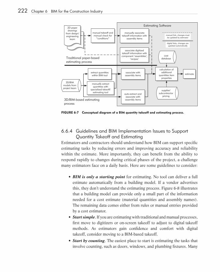
6.6.3 Quantity Takeoff Tool A third alternative, shown generically in Figure 6 - 7 , is to use a specialized quantity takeoff tool that imports data from various BIM tools. This allows estimators to use a takeoff tool specifi cally designed for their needs without having to learn all of the features contained within a given BIM tool. Exam-ples of these are: Exactal (Exactal 2007), Innovaya (Innovaya 2007), and OnCenter (OnCenter 2007). These tools typically include specifi c features that link directly to items and assemblies, annotate the model for ‘ condi-tions ,’ and create visual takeoff diagrams. These tools offer varying levels of support for automated extraction and manual takeoff features. Estimators will need to use a combination of both manual tools and automatic features to support the wide range of takeoff and condition checking they need to perform.
Additional changes to the building model require that any new objects be linked to proper estimating tasks so that accurate cost estimates can be obtained from the building model, depending on the accuracy and level of detail already modeled.
6.6 Quantity Takeoff and Cost Estimating 221
c06.indd 221c06.indd 221 1/16/08 11:38:43 AM1/16/08 11:38:43 AM
222 Chapter 6 BIM for the Construction Industry
6.6.4 Guidelines and BIM Implementation Issues to Support Quantity Takeoff and Estimating
Estimators and contractors should understand how BIM can support specifi c estimating tasks by reducing errors and improving accuracy and reliability within the estimate. More importantly, they can benefi t from the ability to respond rapidly to changes during critical phases of the project, a challenge many estimators face on a daily basis. Here are some guidelines to consider:
BIM is only a starting point for estimating. No tool can deliver a full estimate automatically from a building model. If a vendor advertises this, they don ’ t understand the estimating process. Figure 6 - 8 illustrates that a building model can provide only a small part of the information needed for a cost estimate (material quantities and assembly names). The remaining data comes either from rules or manual entries provided by a cost estimator. Start simple . If you are estimating with traditional and manual processes, fi rst move to digitizers or on - screen takeoff to adjust to digital takeoff methods. As estimators gain confi dence and comfort with digital takeoff, consider moving to a BIM - based takeoff.
Start by counting . The easiest place to start is estimating the tasks that involve counting, such as doors, windows, and plumbing fi xtures. Many
•
•
•
Estimating Software
manual takeoff andmanual check for
“conditions”
2D paperdrawings
from design/engineering
team
calculation ofadditional
quantities itemproperties
3D/BIMmodels fromproject team
manually associatetakeoff information with
assembly items
associate digitizedtakeoff information withcomponent ‘assemblies’,
‘recipes’
manual link, changes mustbe updated by estimator
Traditional paper-basedestimating process
3D/BIM-based estimatingprocess
extract quantitieswithin BIM tool
manually extractquantities with
specialized takeoff/estimating tool
estimateassociate withassembly items
auto-extract andassociate withassembly items
supplier/subcontractor
pricing
digital links, changes areupdated automatically
costdatabase
FIGURE 6 - 7 Conceptual diagram of a BIM quantity takeoff and estimating process.
c06.indd 222c06.indd 222 1/16/08 11:38:43 AM1/16/08 11:38:43 AM
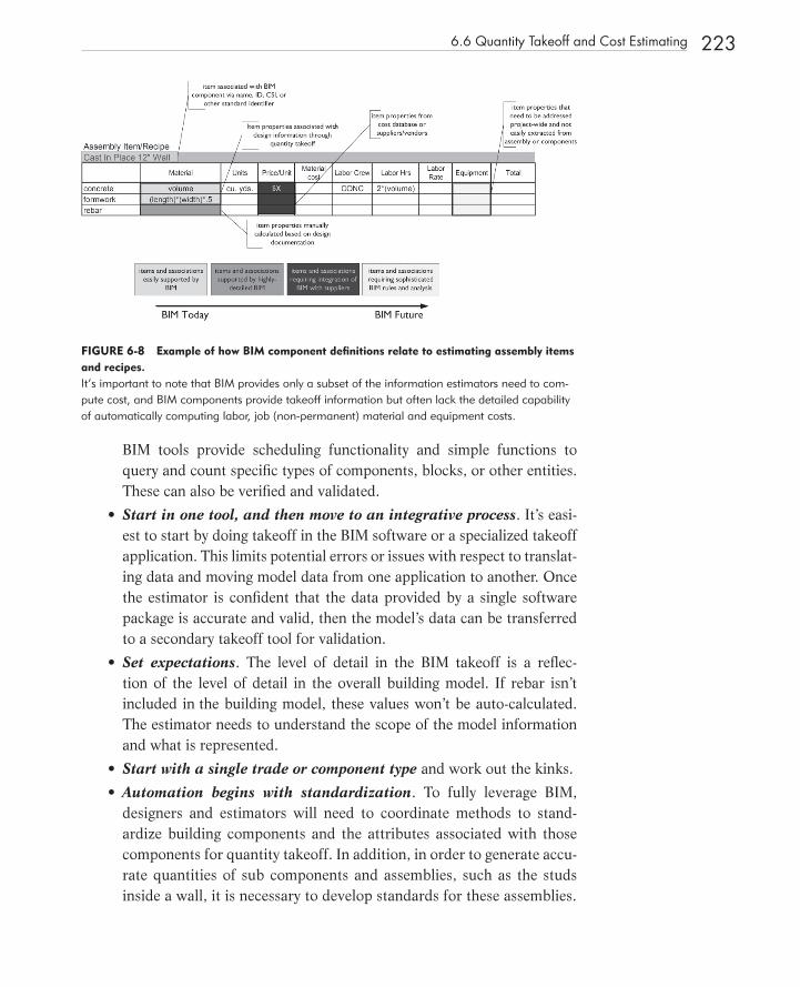
FIGURE 6 - 8 Example of how BIM component defi nitions relate to estimating assembly items and recipes. It ’ s important to note that BIM provides only a subset of the information estimators need to com-pute cost, and BIM components provide takeoff information but often lack the detailed capability of automatically computing labor, job (non - permanent) material and equipment costs.
6.6 Quantity Takeoff and Cost Estimating 223
BIM tools provide scheduling functionality and simple functions to query and count specifi c types of components, blocks, or other entities. These can also be verifi ed and validated.
Start in one tool, and then move to an integrative process . It ’ s easi-est to start by doing takeoff in the BIM software or a specialized takeoff application. This limits potential errors or issues with respect to translat-ing data and moving model data from one application to another. Once the estimator is confi dent that the data provided by a single software package is accurate and valid, then the model ’ s data can be transferred to a secondary takeoff tool for validation.
Set expectations . The level of detail in the BIM takeoff is a refl ec-tion of the level of detail in the overall building model. If rebar isn ’ t included in the building model, these values won ’ t be auto - calculated. The estimator needs to understand the scope of the model information and what is represented.
Start with a single trade or component type and work out the kinks.
Automation begins with standardization . To fully leverage BIM, designers and estimators will need to coordinate methods to stand-ardize building components and the attributes associated with those components for quantity takeoff. In addition, in order to generate accu-rate quantities of sub components and assemblies, such as the studs inside a wall, it is necessary to develop standards for these assemblies.
•
•
•
•
c06.indd 223c06.indd 223 1/16/08 11:38:44 AM1/16/08 11:38:44 AM
224 Chapter 6 BIM for the Construction Industry
6.7 CONSTRUCTION ANALYSIS AND PLANNING
Construction planning and scheduling involves sequencing activities in space and time, considering procurement, resources, spatial constraints, and other concerns in the process. Traditionally, bar charts were used to plan projects but were unable to show how or why certain activities were linked in a given sequence; nor could they calculate the longest (critical) path to complete a project. Today, schedulers typically use Critical Path Method (CPM) scheduling software such as Microsoft Project, Primavera SureTrak, or P3 to create, update, and communi-cate the schedule using a wide variety of reports and displays. These systems show how activities are linked and allow for the calculation of critical path(s) and fl oat values that improve scheduling during a project. Specialized software packages that are better suited to building construction, such as Vico Control, enable schedulers to do line - of - balance scheduling. Sophisticated planning meth-ods for resource - based analysis, including resource - leveling and scheduling with consideration of uncertainty, such as Monte Carlo simulation, are also available in some of the off - the - shelf packages. Other software tools are available for detailed schedules for a short time period of one or two weeks that need to con-sider individual subs, the availability of materials, etc.
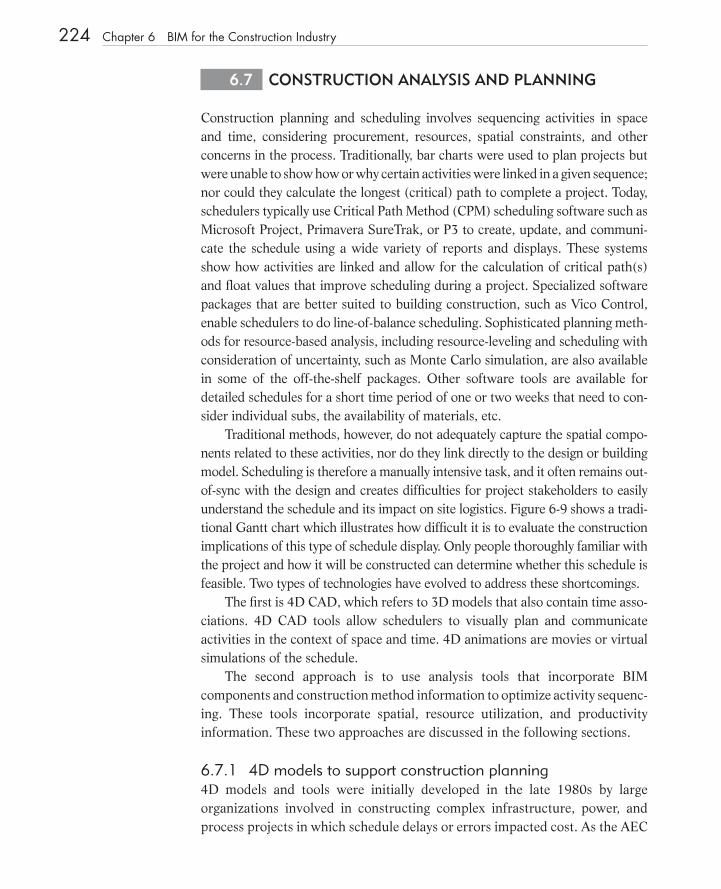
Traditional methods, however, do not adequately capture the spatial compo-nents related to these activities, nor do they link directly to the design or building model. Scheduling is therefore a manually intensive task, and it often remains out - of - sync with the design and creates diffi culties for project stakeholders to easily understand the schedule and its impact on site logistics. Figure 6 - 9 shows a tradi-tional Gantt chart which illustrates how diffi cult it is to evaluate the construction implications of this type of schedule display. Only people thoroughly familiar with the project and how it will be constructed can determine whether this schedule is feasible. Two types of technologies have evolved to address these shortcomings.
The fi rst is 4D CAD, which refers to 3D models that also contain time asso-ciations. 4D CAD tools allow schedulers to visually plan and communicate activities in the context of space and time. 4D animations are movies or virtual simulations of the schedule.
The second approach is to use analysis tools that incorporate BIM components and construction method information to optimize activity sequenc-ing. These tools incorporate spatial, resource utilization, and productivity information. These two approaches are discussed in the following sections.
6.7.1 4D models to support construction planning 4D models and tools were initially developed in the late 1980s by large organizations involved in constructing complex infrastructure, power, and process projects in which schedule delays or errors impacted cost. As the AEC
c06.indd 224c06.indd 224 1/16/08 11:38:45 AM1/16/08 11:38:45 AM
industry adopted 3D tools, construction organizations built manual 4D mod-els and combined snapshots of each phase or period of time in the project. Custom and commercial tools evolved in the mid to late 1990s, facilitating the process by manually creating 4D models with automatic links to 3D geometry, entities, or groups of entities for construction activities (see Figures 6 - 10 , 6 - 11 and 6 - 12). BIM allows schedulers to create, review, and edit 4D models more frequently, which has lead to the implementation of better and more reliable schedules. The following sections discuss the benefi ts of 4D models and the various options schedulers have when producing them.
6.7.2 Benefi ts of 4 D Models 4D simulations function primarily as communication tools for revealing poten-tial bottlenecks and as a method for improving collaboration. Contractors can review 4D simulations to ensure that the plan is feasible and effi cient as possible. The benefi ts of 4D models are:
Communication: Planners can visually communicate the planned con-struction process to all project stakeholders. The 4D model captures both the temporal and spatial aspects of a schedule and communicates this schedule more effectively than a traditional Gantt chart.
•
FIGURE 6 - 9 Sample Gantt chart of a construction schedule for a project involving three buildings and multiple fl oors and areas. Assessing the feasibility or quality of a schedule based on a Gantt chart is often diffi cult for many project participants and requires manually associating each activity with areas or components in the project since there are no visual associations with the referenced areas, such as “ Area 10 ” to a drawing or diagram.
6.7 Construction Analysis and Planning 225
c06.indd 225c06.indd 225 1/16/08 11:38:45 AM1/16/08 11:38:45 AM

226 Chapter 6 BIM for the Construction Industry
Multiple stakeholder input: 4D models are often used in community forums to present to laypersons how a project might impact traffi c, access to a hospital, or other critical community concerns.
Site logistics: Planners can manage lay down areas, access to and within the site, location of large equipment, trailers, etc.
Trade coordination: Planners can coordinate the expected time and space fl ow of trades on the site as well as the coordination of work in small spaces.
Compare schedules and track construction progress : Project mana-gers can compare different schedules easily, and they can quickly iden-tify whether the project is on track or behind schedule.
Above all, 4D CAD requires that an appropriate 3D model of the building be linked to a project schedule that, in turn, provides start and end dates and fl oats for each object. There are a number of systems that provide these linkage capabilities.
The above considerations make the use of 4D CAD a relatively expensive process to setup and manage during a project. Prior experience and knowledge of
•
•
•
•
FIGURE 6 - 10 4 D view of construction of Vancouver Convention Center showing foundation and structural steel erection. A tower crane was included in the model to review crane reach, clearances and confl icts. (See color insert for full color fi gure.) Courtesy Pacifi c Project Systems Inc., MTC Design/3D, (4D modeling); Musson Cattell Mackey Partnership, Downs/ Archambault & Partners, LMN Architects ( architects); Glotman SimpsonConsulting Engineers (structural engineers); PCL Constructors Westcoast Inc (CM)
c06.indd 226c06.indd 226 1/16/08 11:38:46 AM1/16/08 11:38:46 AM
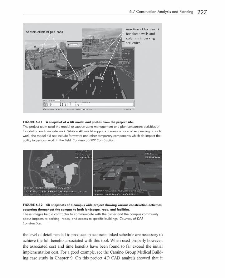
FIGURE 6 - 11 A snapshot of a 4 D model and photos from the project site. The project team used the model to support zone management and plan concurrent activities of foundation and concrete work. While a 4D model supports communication of sequencing of such work, the model did not include formwork and other temporary components which do impact the ability to perform work in the fi eld. Courtesy of DPR Construction.
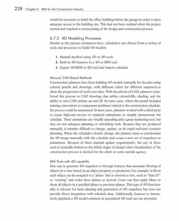
FIGURE 6 - 12 4 D snapshots of a campus wide project showing various construction activities occurring throughout the campus to both landscape, road, and facilities. These images help a contractor to communicate with the owner and the campus community about impacts to parking, roads, and access to specifi c buildings. Courtesy of DPR Construction.
6.7 Construction Analysis and Planning 227
the level of detail needed to produce an accurate linked schedule are necessary to achieve the full benefi ts associated with this tool. When used properly however, the associated cost and time benefi ts have been found to far exceed the initial implementation cost. For a good example, see the Camino Group Medical Build-ing case study in Chapter 9 . On this project 4D CAD analysis showed that it
c06.indd 227c06.indd 227 1/16/08 11:38:47 AM1/16/08 11:38:47 AM
228 Chapter 6 BIM for the Construction Industry
would be necessary to build the offi ce building before the garage in order to have adequate access to the building site. This had not been realized when the project started and required a restructuring of the design and construction process.
6.7.3 4 D Modeling Processes Similar to the options estimators have, schedulers can choose from a variety of tools and processes to build 4D models:
1. Manual method using 3D or 2D tools
2. Built - in 4D features in a 3D or BIM tool
3. Export 3D/BIM to 4D tool and import schedule
Manual, CAD - Based Methods Construction planners have been building 4D models manually for decades using colored pencils and drawings, with different colors for different sequences to show the progression of work over time. With the advent of CAD, planners trans-ferred this process to CAD drawings that utilize colored - fi lls, shading, and the ability to turn CAD entities on and off. In some cases, where the model included naming conventions or component attributes related to the construction schedule, the process could be automated. In most cases, planners worked with a third party to create high - end movies or rendered animations to visually demonstrate the schedule. These animations are visually appealing and a great marketing tool, but they are not adequate planning or scheduling tools. Because they are produced manually, it remains diffi cult to change, update, or do rapid real - time scenario planning. When the schedule ’ s details change, the planner must re - synchronize the 4D image manually with the schedule and create a new set of snapshots or animations. Because of these manual update requirements, the use of these tools is normally limited to the initial stages of design when visualization of the construction process is desired for the client or some outside agency.
BIM Tools with 4D capabilityOne way to generate 4D snapshots is through features that automate fi ltering of objects in a view based on an object property or parameter. For example, in Revit each object can be assigned to a ‘phase’ that is entered as text, such as “June 07” or “existing” and order these phases as desired. Users can then apply fi lters to show all objects in a specifi ed phase or previous phases. This type of 4D function-ality is relevant for basic phasing and generation of 4D snapshots but does not provide direct integration with schedule data. Additionally, features to interac-tively playback a 4D model common in specialized 4D tools are not provided.
c06.indd 228c06.indd 228 1/16/08 11:38:49 AM1/16/08 11:38:49 AM

Most BIM tools don’t have built-in ‘date’ or ‘time’ capabilities, and require specifi c 4D modules or add-on tools to directly link to schedule data. Table 6-1 provides a brief overview of both built-in 4D features and add-on 4D functional-ity available for the popular BIM tools.
Due to the shortcomings inherent in manual and CAD/BIM - based 4D mod-eling tools, several software vendors began offering specialized 4D tools for producing 4D models from 3D models and schedules. These tools facilitate the production and editing of 4D models and provide the scheduler with numerous features for customizing and automating production of the 4D model. Typically, these tools require that data from a 3D model be imported from a CAD or BIM application. In most cases, the extracted data is limited to geometry and a min-imal set of entity or component properties, such as ‘ name’, ‘ color ’, and a group or hierarchy level. The scheduler imports relevant data into the 4D tool, then ‘links’ these components to construction activities, and associates them with types or visual behaviors. Figure 6 - 13 illustrates two approaches to creating the 4D model. The top part shows how a series of snapshots of the construction process can be created from 2D drawings. The lower portion illustrates how a true 4D model can be created from a 3D model linked to a construction sched-ule using specialized 4D software. Figure 6 - 14 shows the types of data sets that are used by 4D software to generate the 4D model.
6.7 Construction Analysis and Planning 229
Table 6-1 Selected BIM tools with 4D capability
Company Product Remarks
Bentley ProjectWise Navigator See Bentley in table 6-2 below
Autodesk Revit Architecture Revit is the only BIM tool with some built-in 4D capability for basic 4D phasing. Each Revit object includes param-eters for “phasing” that allow users to assign a “phase”, to an object and then use Revit’s view properties to view different phases and create 4D snapshots. It is not pos-sible to ’playback’ a model, however. Via the API, users can link to scheduling applications and exchange data with tools like MS Project to automate some 4D entry.
Gehry Technologies
Digital Project An add-on product, Construction Planning and Coordi-nation, allows users to link 3D components to Primav-era or MS Project activities with their associated data and generate 4D simulation analysis. Construction re-lated objects need to be added (and removed when appropriate) to DP model. Changes to Primavera or MS Project schedule are propagated to linked DP model.
Graphisoft VICO Constructor Simulation Module for ArchiCAD
See VICO in table 6-2 below
c06.indd 229c06.indd 229 1/16/08 11:38:50 AM1/16/08 11:38:50 AM
230 Chapter 6 BIM for the Construction Industry
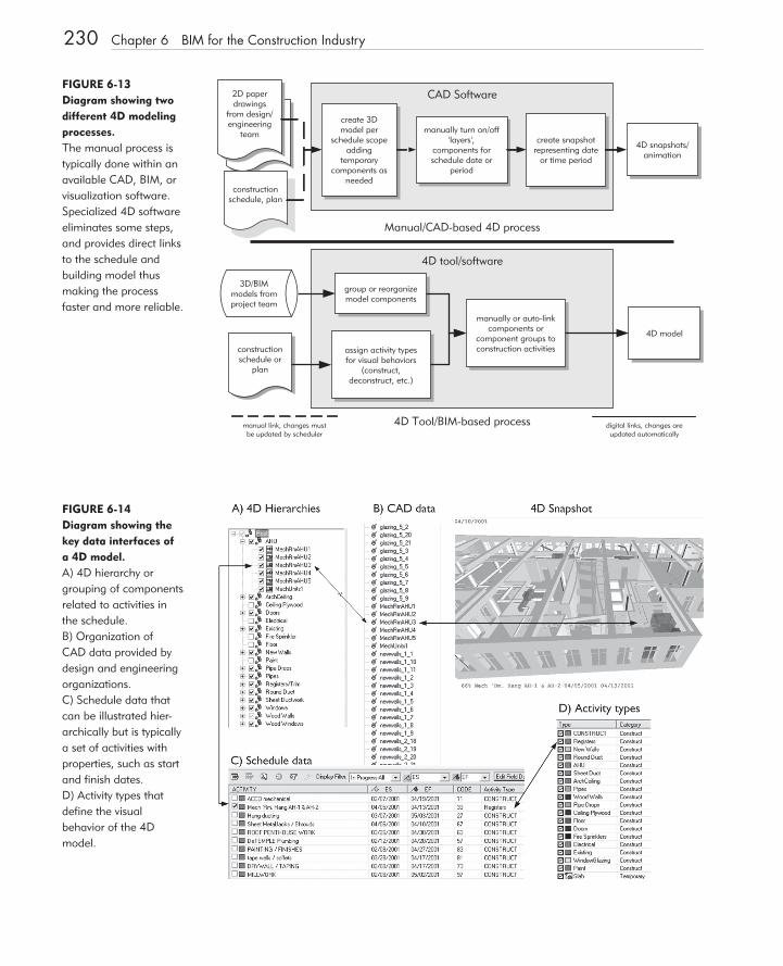
FIGURE 6 - 13 Diagram showing two different 4 D modeling processes. The manual process is typically done within an available CAD, BIM, or visualization software. Specialized 4D software eliminates some steps, and provides direct links to the schedule and building model thus making the process faster and more reliable.
CAD Software
4D tool/software
manually turn on/off'layers',
components forschedule date or
period
2D paperdrawings
from design/engineering
team
3D/BIMmodels fromproject team
create snapshotrepresenting date
or time period
create 3Dmodel per
schedule scopeadding
temporarycomponents as
needed
manual link, changes mustbe updated by scheduler
Manual/CAD-based 4D process
4D Tool/BIM-based process
group or reorganizemodel components
manually or auto-linkcomponents or
component groups toconstruction activities
4D model
digital links, changes areupdated automatically
4D snapshots/animation
constructionschedule, plan
constructionschedule or
plan
assign activity typesfor visual behaviors
(construct,deconstruct, etc.)
FIGURE 6 - 14 Diagram showing the key data interfaces of a 4 D model. A) 4D hierarchy or grouping of components related to activities in the schedule. B) Organization of CAD data provided by design and engineering organizations. C) Schedule data that can be illustrated hier-archically but is typically a set of activities with properties, such as start and fi nish dates. D) Activity types that defi ne the visual behavior of the 4D model.
c06.indd 230c06.indd 230 1/16/08 11:38:50 AM1/16/08 11:38:50 AM
6.7 Construction Analysis and Planning 231
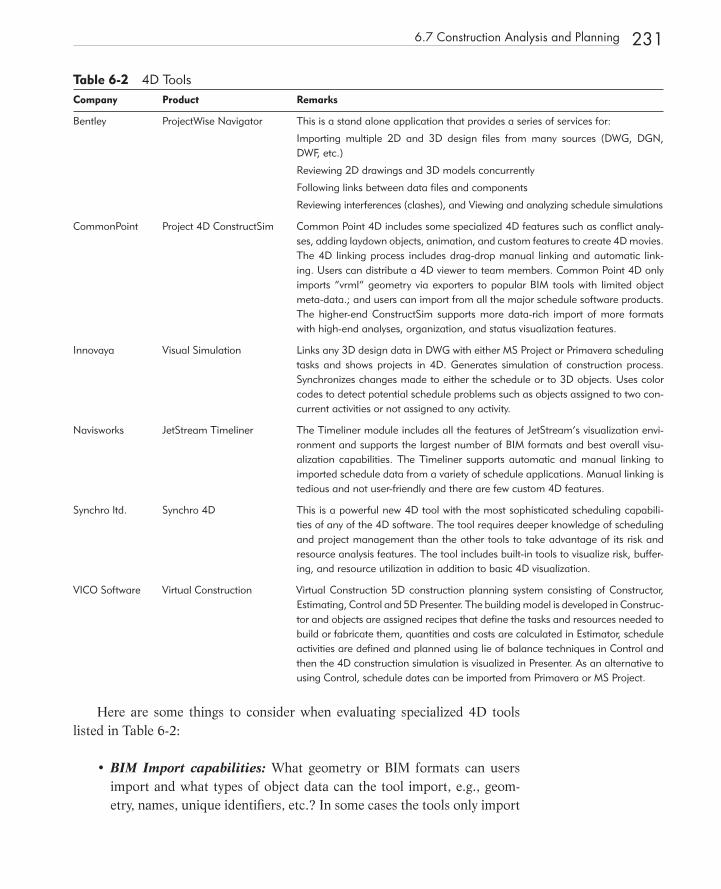
Here are some things to consider when evaluating specialized 4D tools listed in Table 6-2:
BIM Import capabilities: What geometry or BIM formats can users import and what types of object data can the tool import, e.g., geom-etry, names, unique identifi ers, etc.? In some cases the tools only import
•
Table 6-2 4D ToolsCompany Product Remarks
Bentley ProjectWise Navigator This is a stand alone application that provides a series of services for:
Importing multiple 2D and 3D design fi les from many sources (DWG, DGN, DWF, etc.)
Reviewing 2D drawings and 3D models concurrently
Following links between data fi les and components
Reviewing interferences (clashes), and Viewing and analyzing schedule simulations
CommonPoint Project 4D ConstructSim Common Point 4D includes some specialized 4D features such as confl ict analy-ses, adding laydown objects, animation, and custom features to create 4D movies. The 4D linking process includes drag-drop manual linking and automatic link-ing. Users can distribute a 4D viewer to team members. Common Point 4D only imports “vrml” geometry via exporters to popular BIM tools with limited object meta-data.; and users can import from all the major schedule software products. The higher-end ConstructSim supports more data-rich import of more formats with high-end analyses, organization, and status visualization features.
Innovaya Visual Simulation Links any 3D design data in DWG with either MS Project or Primavera scheduling tasks and shows projects in 4D. Generates simulation of construction process. Synchronizes changes made to either the schedule or to 3D objects. Uses color codes to detect potential schedule problems such as objects assigned to two con-current activities or not assigned to any activity.
Navisworks JetStream Timeliner The Timeliner module includes all the features of JetStream’s visualization envi-ronment and supports the largest number of BIM formats and best overall visu-alization capabilities. The Timeliner supports automatic and manual linking to imported schedule data from a variety of schedule applications. Manual linking is tedious and not user-friendly and there are few custom 4D features.
Synchro ltd. Synchro 4D This is a powerful new 4D tool with the most sophisticated scheduling capabili-ties of any of the 4D software. The tool requires deeper knowledge of scheduling and project management than the other tools to take advantage of its risk and resource analysis features. The tool includes built-in tools to visualize risk, buffer-ing, and resource utilization in addition to basic 4D visualization.
VICO Software Virtual Construction Virtual Construction 5D construction planning system consisting of Constructor, Estimating, Control and 5D Presenter. The building model is developed in Construc-tor and objects are assigned recipes that defi ne the tasks and resources needed to build or fabricate them, quantities and costs are calculated in Estimator, schedule activities are defi ned and planned using lie of balance techniques in Control and then the 4D construction simulation is visualized in Presenter. As an alternative to using Control, schedule dates can be imported from Primavera or MS Project.
c06.indd 231c06.indd 231 1/16/08 11:38:51 AM1/16/08 11:38:51 AM
232 Chapter 6 BIM for the Construction Industry
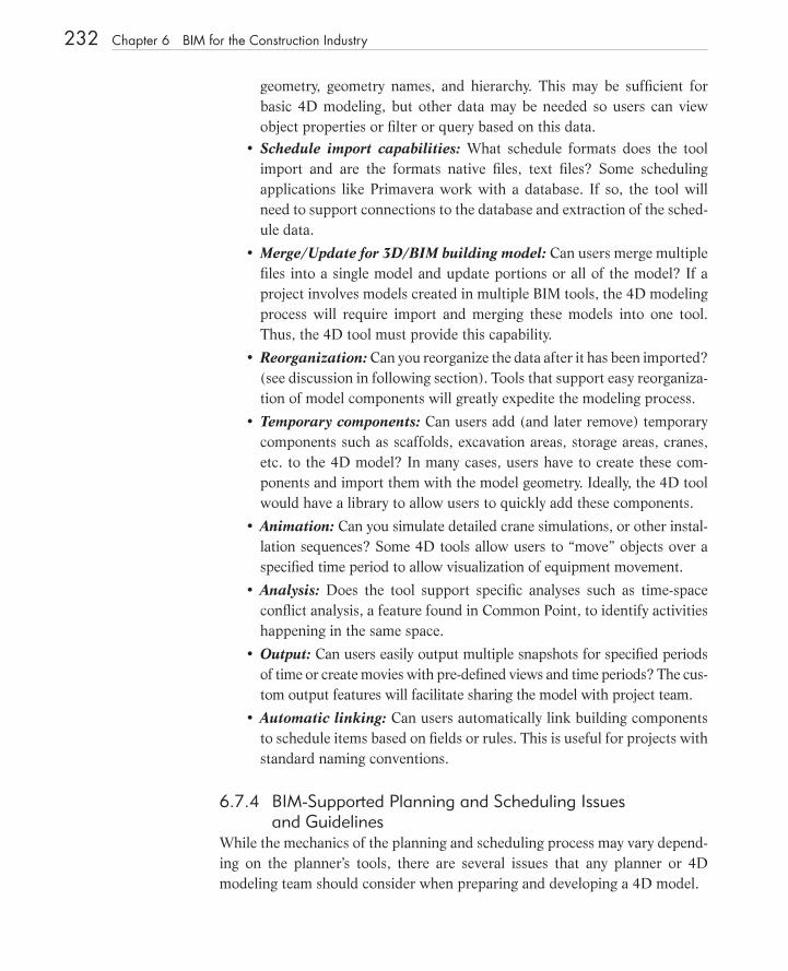
geometry, geometry names, and hierarchy. This may be suffi cient for basic 4D modeling, but other data may be needed so users can view object properties or fi lter or query based on this data.Schedule import capabilities: What schedule formats does the tool import and are the formats native fi les, text fi les? Some scheduling applications like Primavera work with a database. If so, the tool will need to support connections to the database and extraction of the sched-ule data.
Merge/Update for 3D/BIM building model: Can users merge multiple fi les into a single model and update portions or all of the model? If a project involves models created in multiple BIM tools, the 4D modeling process will require import and merging these models into one tool. Thus, the 4D tool must provide this capability.
Reorganization: Can you reorganize the data after it has been imported? (see discussion in following section). Tools that support easy reorganiza-tion of model components will greatly expedite the modeling process.
Temporary components: Can users add (and later remove) temporary components such as scaffolds, excavation areas, storage areas, cranes, etc. to the 4D model? In many cases, users have to create these com-ponents and import them with the model geometry. Ideally, the 4D tool would have a library to allow users to quickly add these components.
Animation: Can you simulate detailed crane simulations, or other instal-lation sequences? Some 4D tools allow users to “move” objects over a specifi ed time period to allow visualization of equipment movement.
Analysis: Does the tool support specifi c analyses such as time-space confl ict analysis, a feature found in Common Point, to identify activities happening in the same space.
Output: Can users easily output multiple snapshots for specifi ed periods of time or create movies with pre-defi ned views and time periods? The cus-tom output features will facilitate sharing the model with project team.
Automatic linking: Can users automatically link building components to schedule items based on fi elds or rules. This is useful for projects with standard naming conventions.
6.7.4 BIM - Supported Planning and Scheduling Issues and Guidelines
While the mechanics of the planning and scheduling process may vary depend-ing on the planner ’ s tools, there are several issues that any planner or 4D modeling team should consider when preparing and developing a 4D model.
•
•
•
•
•
•
•
•
c06.indd 232c06.indd 232 1/16/08 11:38:51 AM1/16/08 11:38:51 AM
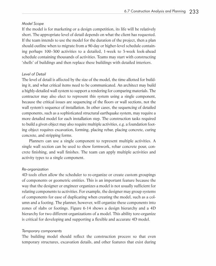
Model Scope If the model is for marketing or a design competition, its life will be relatively short. The appropriate level of detail depends on what the client has requested. If the team intends to use the model for the duration of the project, then a plan should outline when to migrate from a 90 - day or higher - level schedule contain-ing perhaps 100 – 300 activities to a detailed, 1-week to 3 - week look - ahead schedule containing thousands of activities. Teams may start with constructing ‘shells’ of buildings and then replace these buildings with detailed interiors.
Level of Detail The level of detail is affected by the size of the model, the time allotted for build-ing it, and what critical items need to be communicated. An architect may build a highly - detailed wall system to support a rendering for comparing materials. The contractor may also elect to represent this system using a single component, because the critical issues are sequencing of the fl oors or wall sections, not the wall system ’ s sequence of installation. In other cases, the sequencing of detailed components, such as a sophisticated structural earthquake system, may require a more detailed model for each installation step. The construction tasks required to build a given object may also require multiple activities, e.g. a foundation foot-ing object requires excavation, forming, placing rebar, placing concrete, curing concrete, and stripping forms.
Planners can use a single component to represent multiple activities. A single wall section can be used to show formwork, rebar concrete pour, con-crete fi nishing, and wall fi nishes. The team can apply multiple activities and activity types to a single component.
Re - organization 4D tools often allow the scheduler to re - organize or create custom groupings of components or geometric entities. This is an important feature because the way that the designer or engineer organizes a model is not usually suffi cient for relating components to activities. For example, the designer may group systems of components for ease of duplicating when creating the model, such as a col-umn and a footing. The planner, however, will organize these components into zones of slabs or footings. Figure 6 - 14 shows a design hierarchy and a 4D hierarchy for two different organizations of a model. This ability tore - organize is critical for developing and supporting a fl exible and accurate 4D model.
Temporary components The building model should refl ect the construction process so that even temporary structures, excavation details, and other features that exist during
6.7 Construction Analysis and Planning 233
c06.indd 233c06.indd 233 1/16/08 11:38:52 AM1/16/08 11:38:52 AM

234 Chapter 6 BIM for the Construction Industry
construction can be shown in the 4D simulation. Figure 6 - 15 shows a 4D model that contains scaffolding to help construction planners evaluate safety and constructability issues. The scaffolding is necessary because it will infl u-ence spatial constraints for people and equipment.
Decomposition and Aggregation Objects shown as a single entity, such as a slab, may need to be broken into por-tions to show how they will be constructed. Another issue that planners face is how to break up specifi c components, such as walls or roofs, that a designer or engineer would model as a single component but the planner would divide or break - up into zones. Most specialized tools do not provide this capability, and the planner must perform these ‘break - ups’ within the 3D/BIM tool.
Schedule Properties Early start and completion dates are often used for 4D simulation. It may be desirable however, to explore other dates, such as a late start or fi nish or a leveled start or fi nish, to view the impact of alternative schedules on the visual simula-tion of the construction process. Additionally, other schedule properties are valu-able in the 4D modeling process that are often project - specifi c. For example, in one study a team associated specifi c activities with the number of hospital beds that were either taken out - of - service or made operational so that the team could visualize, at any time, the number of hospital beds available and ensure that a minimum number could remain in use. It is also possible to code each activity
FIGURE 6 - 15 A 4 D model snapshot showing scaffolding. Adding temporary equipment is often critical for determining the feasibility of the schedule; the details allow subcontractors and planners to visu-ally assess safety and constructability issues. (See color insert for full color fi gure.) Image pro-vided courtesy of M.A. Mortenson, Inc.
c06.indd 234c06.indd 234 1/16/08 11:38:52 AM1/16/08 11:38:52 AM
with a property titled ‘ Area, ’ or ‘ Responsibility ’ so that the model can show who is responsible for certain activities and quickly identify trades working near each other to improve coordination.
6.8 INTEGRATION WITH COST AND SCHEDULE CONTROL AND OTHER MANAGEMENT FUNCTIONS
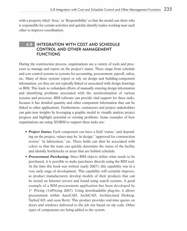
During the construction process, organizations use a variety of tools and proc-esses to manage and report on the project ’ s status. These range from schedule and cost control systems to systems for accounting, procurement, payroll, safety, etc. Many of these systems report or rely on design and building - component information, yet they are not typically linked or associated with design drawings or BIM. This leads to redundant efforts of manually entering design information and identifying problems associated with the synchronization of various systems and processes. BIM software can provide vital support for these tasks, because it has detailed quantity and other component information that can be linked to other applications. Furthermore, contractors and project stakeholders can gain new insights by leveraging a graphic model to visually analyze project progress and highlight potential or existing problems. Some examples of how organizations are using 3D/BIM to support these tasks are:
Project Status: Each component can have a fi eld ‘ status,’ and depend-ing on the project, values may be ‘ in design,’ ‘ approved for construction review,’ ‘ in fabrication,’ etc. These fi elds can then be associated with colors so that the team can quickly determine the status of the facility and identify bottlenecks or areas that are behind schedule.
Procurement Purchasing: Since BIM objects defi ne what needs to be purchased, it is possible to make purchases directly using the BIM tool. At the time this book was written (early 2007), this capability was in a very early stage of development. This capability will certainly improve, as product manufacturers develop models of their products that can be stored on Internet servers and found using search systems. A good example of a BIM procurement application has been developed by 1 st Pricing (1stPricing 2007). Using downloadable plug - ins , it allows procurement within AutoCAD, ArchiCAD, Architectural Desktop, TurboCAD, and soon Revit. This product provides real - time quotes on doors and windows delivered to the job site based on zip code. Other types of components are being added to the system.
•
•
6.8 Integration with Cost and Schedule Control and Other Management Functions 235
c06.indd 235c06.indd 235 1/16/08 11:38:53 AM1/16/08 11:38:53 AM
236 Chapter 6 BIM for the Construction Industry
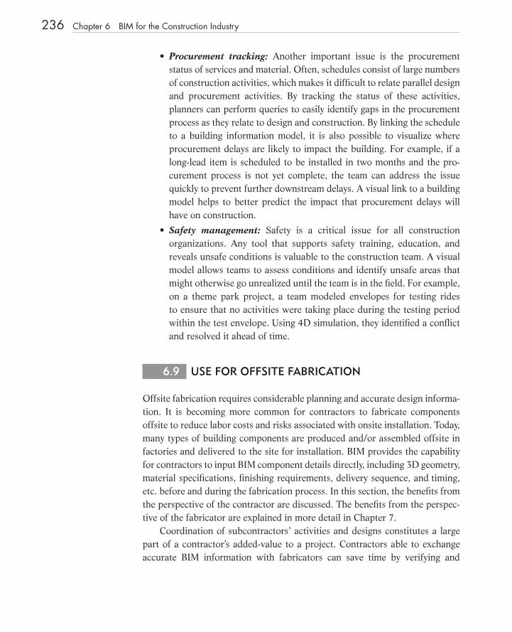
Procurement tracking: Another important issue is the procurement status of services and material. Often, schedules consist of large numbers of construction activities, which makes it diffi cult to relate parallel design and procurement activities. By tracking the status of these activities, planners can perform queries to easily identify gaps in the procurement process as they relate to design and construction. By linking the schedule to a building information model, it is also possible to visualize where procurement delays are likely to impact the building. For example, if a long - lead item is scheduled to be installed in two months and the pro-curement process is not yet complete, the team can address the issue quickly to prevent further downstream delays. A visual link to a building model helps to better predict the impact that procurement delays will have on construction.
Safety management: Safety is a critical issue for all construction organizations. Any tool that supports safety training, education, and reveals unsafe conditions is valuable to the construction team. A visual model allows teams to assess conditions and identify unsafe areas that might otherwise go unrealized until the team is in the fi eld. For example, on a theme park project, a team modeled envelopes for testing rides to ensure that no activities were taking place during the testing period within the test envelope. Using 4D simulation, they identifi ed a confl ict and resolved it ahead of time.
6.9 USE FOR OFFSITE FABRICATION
Offsite fabrication requires considerable planning and accurate design informa-tion. It is becoming more common for contractors to fabricate components offsite to reduce labor costs and risks associated with onsite installation. Today, many types of building components are produced and/or assembled offsite in factories and delivered to the site for installation. BIM provides the capability for contractors to input BIM component details directly, including 3D geometry, material specifi cations, fi nishing requirements, delivery sequence, and timing, etc. before and during the fabrication process. In this section, the benefi ts from the perspective of the contractor are discussed. The benefi ts from the perspec-tive of the fabricator are explained in more detail in Chapter 7 .
Coordination of subcontractors ’ activities and designs constitutes a large part of a contractor ’ s added - value to a project. Contractors able to exchange accurate BIM information with fabricators can save time by verifying and
•
•
c06.indd 236c06.indd 236 1/16/08 11:38:53 AM1/16/08 11:38:53 AM
validating the model. This reduces errors and allows fabricators to participate earlier in the pre - planning and construction process.
There are excellent examples of close coordination and exchange of models between contractors and fabricators in the steel and sheet metal industries. As discussed in Chapter 7 , many steel fabricators leverage 3D technologies to manage and automate the steel fabrication process. The adoption of product model exchange formats, such as the CIS/2 format (explained in detail in Chapter 3 ) (CIS/2 2007), greatly facilitates the exchange of information between design and engineering, contractors, and fabricators. These conditions allow project teams to coordinate and optimize the sequence of steel or sheet metal. In Chapter 9 , the benefi ts of a close digital relationship between a con-tractor and a fabricator are captured in several case studies.
The structural steel industry is well - positioned to leverage BIM due to the efforts of the AISC (AISC 2007) and the development of the CIS/2 (CIS/2 2007) format. Other standards are being developed for precast concrete but are not yet in commercial use. The National BIM Standards effort (NIBS 2007) considers how to use building information models to provide information for fabrication. The NBIMS is reviewed in Chapter 3 . Further details, including BIM technology requirements and available software products, are discussed in Chapter 7 .
6.10 USE OF BIM ONSITE: VERIFICATION, GUIDANCE, AND TRACKING OF CONSTRUCTION ACTIVITIES
Contractors must fi eld - verify the installation of building components to ensure that dimensional and performance specifi cations are met. When errors are found, the contractor must spend further time rectifying them. The building model can be used to verify that actual construction circumstances match those shown in the model. Note that even when a project team creates an accurate model, human error during installation remains a possibility, and catching these errors as they occur or as soon as possible has great value. An example of this occurred on the Letterman Digital Arts Center (LDAC) in San Francisco, where the project team built a complete model after the project had been designed and subsequently documented a fi eld error in a report (Boryslawski 2006) as described in the fol-lowing excerpt:
“ During one of the daily rounds of onsite photography, we recognized a criti-cal error shown in the positioning of concrete formwork, which was quickly confi rmed by referencing the BIM. This error occurred when the formwork
6.10 Use of BIM Onsite: Verifi cation, Guidance, and Tracking of Construction Activities 237
c06.indd 237c06.indd 237 1/16/08 11:38:53 AM1/16/08 11:38:53 AM
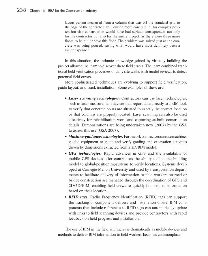
238 Chapter 6 BIM for the Construction Industry
layout person measured from a column that was off the standard grid to the edge of the concrete slab. Pouring more concrete in this complex post - tension slab construction would have had serious consequences not only for the contractor but also for the entire project, as there were three more fl oors to be built above this fl oor. The problem was solved just as the con-crete was being poured, saving what would have most defi nitely been a major expense. ”
In this situation, the intimate knowledge gained by virtually building the project allowed the team to discover these fi eld errors. The team combined tradi-tional fi eld - verifi cation processes of daily site walks with model reviews to detect potential fi eld errors.
More sophisticated techniques are evolving to support fi eld verifi cation, guide layout, and track installation. Some examples of these are:
Laser scanning technologies: Contractors can use laser technologies, such as laser measurement devices that report data directly to a BIM tool, to verify that concrete pours are situated in exactly the correct location or that columns are properly located. Laser scanning can also be used effectively for rehabilitation work and capturing as - built construction details. Demonstrations are being undertaken now (2007) by the GSA to assess this use (GSA 2007).
Machine - guidance technologies: Earthwork contractors can use machine - guided equipment to guide and verify grading and excavation activities driven by dimensions extracted from a 3D/BIM model.
GPS technologies: Rapid advances in GPS and the availability of mobile GPS devices offer contractors the ability to link the building model to global - positioning - systems to verify locations. Systems devel-oped at Carnegie - Mellon University and used by transportation depart-ments to facilitate delivery of information to fi eld workers on road or bridge construction are managed through the coordination of GPS and 2D/3D/BIM, enabling fi eld crews to quickly fi nd related information based on their location.
RFID tags : Radio Frequency Identifi cation (RFID) tags can support the tracking of component delivery and installation onsite. BIM com-ponents that include references to RFID tags can automatically update with links to fi eld scanning devices and provide contractors with rapid feedback on fi eld progress and installation.
The use of BIM in the fi eld will increase dramatically as mobile devices and methods to deliver BIM information to fi eld workers becomes commonplace.
•
•
•
•
c06.indd 238c06.indd 238 1/16/08 11:38:54 AM1/16/08 11:38:54 AM

6.11 IMPLICATIONS FOR CONTRACT AND ORGANIZATIONAL CHANGES
The above descriptions of BIM - supported work processes for contractors emphasize the advantages of early and continual collaboration of the project team so that key project participants are involved in the development of the virtual model. Contractors of all types that integrate their practice around BIM, as opposed to traditional 2D CAD, will reap the greatest advantages. Projects that involve designers as well as general and major subcontractors, by incorpo-rating constructability, cost, and construction planning knowledge earlier in the process, will experience project - wide benefi ts for all team members. The advantages that an integrated, collaborative, BIM - supported approach can bring will make it a favored and widely used method in the future.
This organizational approach will, of course, require new contracts that encourage close collaboration and sharing of information, as well as a sharing of the technology ’ s associated benefi ts. A new approach to sharing risks and setting fees may also be required, because the increased emphasis on early collaboration means that efforts by team members and the benefi ts they pro-duce may change. Advanced owners are already experimenting with new ideas for exploring how to better incorporate contractor involvement through a BIM - driven process. Some of these are discussed in the case studies in Chapter 9 .
The Associated General Contractors (AGC) is closely following the impli-cations of BIM for their members. In October, 2006, the AGC published a 48 - page document titled, “ The Contractor ’ s Guide to BIM, ” (AGC 2006) which is available at their web site (free for their members, at a cost for others). The report is based on fi rst - hand experience provided by contractors that have already used BIM. The guide discusses the implementation of BIM using 2D drawings produced by the design team and contrasts this with the faster and more accurate process of starting with a 3D/building model generated by the design team. The guide suggests that an experienced digital modeler can create a building model from 2D drawings in one - to - two weeks at a cost of 0.1% to 0.5% of the total construction costs. Contractors must balance these costs with the many potential benefi ts of BIM, as discussed earlier in this chapter.
With respect to changes in management responsibilities, “ The Contractor ’ s Guide to BIM ” (AGC 2006) says:
“ Whether the design is issued in the form of 2D printed documents or a 3D electronic media or in a combination of both, the responsibilities of the mem-bers of the project team remain unchanged. The important issue is to ensure that project team members thoroughly understand the nature and exactitude of the information that is being conveyed. ”
6.11 Implications for Contract and Organizational Changes 239
c06.indd 239c06.indd 239 1/16/08 11:38:54 AM1/16/08 11:38:54 AM
It adds:
“ Contractors and Construction Managers need to recognize that coordination whether with BIM technology or a light table is a core service not an added service. BIM tools that can facilitate a great deal of coordination are now avail-able and when applied appropriately they can reduce the cost and time of con-struction. The question is not whether BIM will be used on a project, but to what extent it will be used. It is known that BIM coordination improves com-munication, which decreases construction cost and time, thus reducing risk. Contractors and Construction Managers have a responsibility to evaluate the costs of various implementation processes and provide the results of this evalu-ation to Owners and design teams in quantifi able terms. As the leaders of construction coordination, Contractors and Construction Managers have a responsibility to encourage and facilitate the sharing and dis-tribution of BIM technology on a project. They must also understand and con-vey the nature of the information that is being shared. Appropriate contract language that will foster the open sharing of BIM information must be developed. The contract language can not alter the relationships of the project team members or change their responsibilities beyond their ability to perform. As an example, if a designer approves an electronic fi le prepared by a detailer, and this fi le contains a dimensional inaccuracy, the designer must be protected to the same extent that they would had the approval document been a printed drawing. ”
Finally, while the guide does not recommend specifi c contract changes for accommodating BIM, it suggests that all parties agree to rely on the model (as opposed to 2D drawings in cases where the two representations do not agree); it suggests that all members of the team be given access to and take responsi-bility for their part of the model; and it recommends that an audit trail be maintained that tracks all changes made to the model. Clearly, this is an area that is rapidly evolving with the use of BIM tools.
6.12 BIM IMPLEMENTATION
Contractors working in close collaboration with project teams during the design phase will encounter fewer barriers to BIM adoption compared to contractors working in a design - bid - build environment. In the latter case, the collaboration process does not start until the job has been awarded to the low bid contractor; in the former, the contractor is involved with design decisions and can contribute construction knowledge to the design. The same applies to the subcontractors that participate in the project.
240 Chapter 6 BIM for the Construction Industry
c06.indd 240c06.indd 240 1/16/08 11:38:54 AM1/16/08 11:38:54 AM
6.12 BIM Implementation 241
In both cases, the contractor needs to understand how the use of 3D/BIM, rather than 2D drawings, can be used to support coordination, estimating, sched-uling, and project management. A good implementation plan involves making sure that management and other key staff members acquire a thorough under-standing of how BIM supports specifi c work processes. This should be done at a company - wide level, although any particular project could be used as a starting point. If the architects and other designers on the company ’ s projects are not all using BIM technology, it will be necessary for the contractor to build models that are appropriate for the above functions. This will expose them to a deeper under-standing of model building and the required standards — for colors, objects, construction knowledge, etc. — that need to be incorporated into the model. Training can be obtained from BIM software fi rms or from specialized consult-ants. The cost of building the model, estimated at about 0.1% of construction cost (see the Camino Group Medical Building case study in Chapter 9 for discus-sion of model building cost), will be more than offset by the eventual savings in errors, shortened project durations, better use of prefabrication options, fewer workers in the fi eld, and improved collaboration among the team. This topic is discussed in greater detail for subcontractors and fabricators in Chapter 7 .
1. There is tremendous variation in the size and type of construction companies. In 2004, what percent of fi rms were composed of 1 to 9 people? In what sector were a majority of these fi rms?
2. What are the main advantages of design - build over design - bid - build contracts? Why does the use of BIM favor the design - build contract? For public projects, why are design - bid - build contracts often preferred (see also Chapter 1 , Section 1.1.2 )?
3. From the contractor ’ s point - of - view, what kinds of informa-tion should a building model contain? If the architect uses BIM to design a building, what information needed by the contractor is NOT likely to be present?
(Continued)
Chapter 6 Discussion Questions
c06.indd 241c06.indd 241 1/16/08 11:38:55 AM1/16/08 11:38:55 AM

242 Chapter 6 BIM for the Construction Industry
4. What approaches are available to develop a building model that can be used by the contractor? What are the limitations and benefi ts of each approach?
5. What level - of - detail is needed in a building model for useful clash detection? What are the reasons for detecting soft as opposed to hard clashes? What role do subcon-tractors play in the clash detection process?
6. What are the main advantages and limitations of using BIM for preparing a cost estimate? How can an estimator link the building model to an estimating system?
7. What are the basic requirements for performing a 4D analysis of a construction schedule? What are the contractor ’ s options for obtaining the information needed to carry out this analysis? What major benefi ts can be obtained from this analysis?
8. How can BIM be linked to cost and schedule control systems? What advantages does this provide?
9. What are the main advantages of using BIM for procure-ment? Why is it still diffi cult to do this?
10. What are the requirements for using a building model for off - site fabrication? What types of exchange standards are needed for fabrication of steel members?
11. What types of organizational and contractual changes are needed for effective BIM use?
c06.indd 242c06.indd 242 1/16/08 11:38:55 AM1/16/08 11:38:55 AM