BIM Delivery Guidelines...3D geometry with basic information shall be developed for existing...
22
BIM Delivery Guidelines March 30, 2020 Prepared for Padre Dam Municipal Water District 9300 Fanita Parkway Santee, CA 92071 Prepared by
Transcript of BIM Delivery Guidelines...3D geometry with basic information shall be developed for existing...
BIM Delivery Guidelines
March 30, 2020
Prepared for
Padre Dam Municipal Water District 9300 Fanita Parkway
Santee, CA 92071
Prepared by

BIM Delivery Guidelines i
Table of Contents
List of Tables ................................................................................................................................. ii
List of Figures................................................................................................................................ ii
List of Appendices ......................................................................................................................... ii
Section 1: Introduct ion ............................................................................... 1-1
1.1 Purpose ............................................................................................... 1-1
1.2 Abbreviations ...................................................................................... 1-2
Section 2: Model Development ................................................................... 2-1
2.1 Level of Development.......................................................................... 2-1
2.2 Model Progression .............................................................................. 2-2
2.3 Types of Models .................................................................................. 2-2
2.3.1 System Models ......................................................................... 2-2
2.3.2 Federated Models .................................................................... 2-2
Section 3: BIM Goals, Uses, and Planning ................................................. 3-1
3.1 BIM Goals ........................................................................................... 3-1
3.2 BIM Uses ............................................................................................. 3-1
3.2.1 Existing Conditions Modeling ................................................... 3-1
3.2.2 Design Authoring...................................................................... 3-2
3.2.3 Engineering Analysis ................................................................ 3-2
3.2.4 3D Coordination ....................................................................... 3-2
3.2.5 Site Analysis............................................................................. 3-2
3.2.6 Design Reviews ....................................................................... 3-2
3.2.7 Cost Reliability & Management ................................................ 3-2
3.2.8 Phase Planning/Construction Sequence Analysis (4D Modeling) ................................................................................. 3-3
3.2.9 Site Utilization Planning ........................................................... 3-3
3.2.10 Record Modeling ...................................................................... 3-3
3.2.11 Enterprise Asset Management ................................................. 3-3
3.2.12 Facility Maintenance Planning ................................................. 3-3
3.3 BIM Execution Planning ...................................................................... 3-4
Section 4: Production ................................................................................. 4-6
4.1 Data Constructs................................................................................... 4-6
4.1.1 Model Element Parameters ...................................................... 4-6
4.1.1.1 Object ID and Common Name ............................... 4-6
4.1.1.2 Additional Object Attributes ................................... 4-7
4.2 Software Platforms & File Formats ...................................................... 4-7
4.2.1 Software Resources ................................................................. 4-8
Table of Contents (cont’d)
BIM Delivery Guidelines ii
4.2.2 Revit Models ............................................................................ 4-8
4.3 File Management, Collaboration, and Security ................................... 4-8
4.4 Deliverables ........................................................................................ 4-9
4.5 Review Processes ............................................................................... 4-9
Section 5: References ................................................................................. 5-1
List of Tables
Table 1-1: List of Abbreviations .................................................................................................. 1-2
Table 2-1: LOD Level Criteria .................................................................................................... 2-1
Table 4-1: Software Platforms .................................................................................................... 4-7
Table 4-2: Model Walkthrough Reviews .................................................................................. 4-10
List of Figures
Figure 3-1: BIM Use Process Map Example .............................................................................. 3-5
List of Appendices
Appendix A: Model Progression Milestones ......................................................................... A-1

BIM Delivery Guidelines Page 1-1
Section 1: Introduction
1.1 Purpose
This document defines the approach that shall be used to apply Building Information Modeling (BIM) techniques for the design and construction of facilities for the East County Advanced Water Purification Project. It is intended to serve as an update and companion to the Computer Aided Design (CAD) Standards (as documented in the CAD Memorandum for the ECAWP Project. It is recognized that multiple, specialized software platforms will be used to develop designs for facility construction under this project. It is important to bear in mind, however, that uniformity of construction documents for a given Package is paramount in ensuring successful delivery of quality infrastructure. In general, the presentation, organization, and naming guidelines addressed by the CAD Standards shall be used in the preparation of models and drawings across all platforms. Where certain items do not have a direct equivalent in advanced design software (e.g., the lack of layers in Revit), the designer may exercise some liberty to organize design components into logically named families & parts. Where information may differ between this document and the CAD Standards, the newer information presented in this document shall govern. In addition to the CAD Standards and the BIM Delivery Guidelines (this document), the Design-Build Team for each Package will develop a BIM Execution Plan (BIM XP) which is tailored to the requirements of the respective Package. Due to the relationship between the Packages within the overall Project, each BIM XP shall be coordinated with those developed in prior Packages. This coordination shall be incorporated into the development and review of the BIM XP for each Package.

BIM Delivery Guidelines Page 1-2
1.2 Abbreviat ions
This document makes use of many industry standard abbreviations, which are listed below for ease of reference.
Table 1-1: List of Abbreviations
AIA American Institute of Architects
AWP Advanced Water Purification BIM Building Information Modeling CAD Computer Aided Design CMMS Computerized Maintenance Management System DB Design-Build EAM Enterprise Asset Management ECAWP East County Advanced Water Purification GIS Geographic Information System GMP Guaranteed Maximum Price JPA Joint Powers Authority LOD Level of Development MEA Model Element Author NTP Notice to Proceed O&M Operations and Maintenance P&ID Process and Instrumentation Diagram QA Quality Assurance QC Quality Control XP Execution Plan
BIM Delivery Guidelines Page 2-1
Section 2: Model Development
Starting with schematic design and progressing through design development, construction, and commissioning, each element in the geometry and information models shall develop in a logical manner corresponding to the amount of information available for the element at that point in time. In general, this shall be as outlined below.
2.1 Level of Development
LOD is the level of completeness to which a model element is developed at the end of each project phase. Although we have defined LOD to mean Level of Development for this document, it is also often thought of as Level of Detail. Level of Detail would refer to what an object looks like, such as geometry in a 3D model appearing the same as it does in real life, with its location and dimensions portrayed precisely. Level of Development, however, refers to the engineering behind the object – the level to which calculations or other analysis informs the decision to size and place the object how it’s shown.
The AIA has defined a set of general criteria corresponding to a numerical assignment between 100 (least developed) and 500 (most developed). In addition to different LODs for building element size, shape and definition, there are also different levels of detail that can be associated with the addition of element specific information (non-geometric information) into a 3D Model, such as equipment names, equipment numbers, model numbers, materials, horsepower, and other data. The AIA LODs are listed below with their criteria; additional interpretation by BIMForum and expansion by Pennsylvania State University Computer Integrated Construction Research Group are also included. Both of these groups have been contributing to the advancement of BIM for several years.
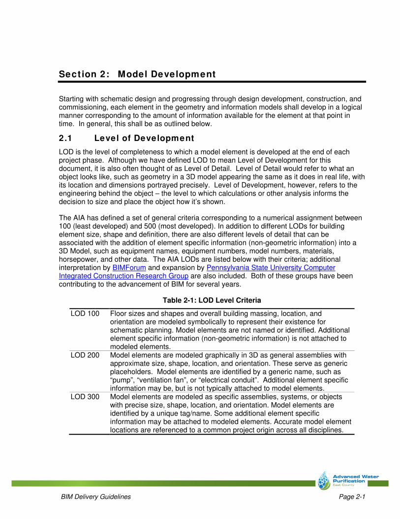
Table 2-1: LOD Level Criteria
LOD 100 Floor sizes and shapes and overall building massing, location, and orientation are modeled symbolically to represent their existence for schematic planning. Model elements are not named or identified. Additional element specific information (non-geometric information) is not attached to modeled elements.
LOD 200 Model elements are modeled graphically in 3D as general assemblies with approximate size, shape, location, and orientation. These serve as generic placeholders. Model elements are identified by a generic name, such as “pump”, “ventilation fan”, or “electrical conduit”. Additional element specific information may be, but is not typically attached to model elements.
LOD 300 Model elements are modeled as specific assemblies, systems, or objects with precise size, shape, location, and orientation. Model elements are identified by a unique tag/name. Some additional element specific information may be attached to modeled elements. Accurate model element locations are referenced to a common project origin across all disciplines.

BIM Delivery Guidelines Page 2-2
LOD 350 Model elements are modeled as specific assemblies, systems, or objects with precise size, shape, location, orientation, and interfaces with other building or process systems systems. Model elements are identified by a unique tag/name. Some additional element specific information may be attached to modeled elements. Parts needed for coordination with other model elements, such as supports and connections, are modeled.
LOD 400 Model elements are modeled as specific assemblies, systems, or objects with precise size, shape, location, orientation, fabrication, assembly, detailing, and installation information. Model elements are identified by unique tag/name. Additional element specific information is typically attached to modeled elements.
LOD 500 Model elements are modeled as constructed assemblies with precise size, shape, location, orientation. Model elements are identified by unique tag/name. Additional element specific information is attached to modeled elements. (e.g., model numbers, maintenance and operation information).
LOD 510 In addition to what’s listed in LOD 500, this level also contains O&M Manuals.
LOD 520 In addition to what’s listed in LOD 500 and 510 this level also contains warranty information.
LOD 530 In addition to what’s listed in LOD 500, 510, and 520, this level also contains submittal information.1
1 Although LOD 530 is not specified for use on this Project, the final product submittals shall be tagged with the same asset identification tag which is used within the information models
2.2 Model Progression
A suggested model progression matrix is included in Appendix A. It is understood that this may not apply universally to all Packages; amendments to this matrix may be proposed to suit a specific Package’s scope. The model progression matrix for a Package shall be included in the project’s BIM Execution Plan, as described later in this document.
2.3 Types of Models
2.3.1 System Models
Each discipline shall develop a system model (one per process unit for plant Packages) comprised of all elements related to the discipline. System models shall be used to assist with coordinating clearances and points of interconnection between disciplines.
2.3.2 Federated Models
A federated model shall be developed by combining the discipline system models into a single amalgamated model to convey the complete design intent for inter-discipline and inter-trade coordination, reference, communication, and collaboration throughout each phase of the project. One federated model shall be developed for each process unit (for plant Packages), and one federated model shall be developed to encompass the entire Package. Construction documents shall be derived from information contained within the federated model.
BIM Delivery Guidelines Page 3-1
Section 3: BIM Goals, Uses, and Planning
3.1 BIM Goals
Meeting schedule and cost expectations is a necessity. Beyond these, the ECAWP JPA has established the following aspirational goals, towards which BIM methods shall be applied:
• Facilitate development of alternatives & enable quicker decision making earlier in the
design phase than with traditional design methods
• Reduction of overall schedule through a tighter integration of planning, analysis, and
design information
• Engage O&M staff during the design process to gain greater buy-in from these key
stakeholders
• Reduction of errors and conflicts in the field (minimizing change orders) by integrating
work planning and construction sequencing and scheduling into the design process
• Improved finished product quality through a more detailed design and review process
• Increasing field productivity and efficiency by visualizing the planned construction
schedule
• Obtaining important operations and maintenance data generated during the design and
construction process for future use by the facility operator for asset management, space
planning, and maintenance scheduling to improve the overall performance of the facility
• Facilitate the ease of data migration from design through construction into O&M-focused
tools such as CMMS and EAM systems
To achieve these goals, a variety of BIM uses shall be employed as addressed in the next section.
3.2 BIM Uses
The BIM XP shall identify and clearly document BIM uses intended for a Package to support the goals stated above. Examples of several BIM uses are presented below with information about how they may apply to a particular Package. Other BIM uses to benefit construction may be incorporated into the project at the discretion of the DB team, such as Cost Estimation, Construction System Design, Digital Fabrication Techniques, etc.
3.2.1 Exist ing Condit ions Modeling
3D geometry with basic information shall be developed for existing conditions to the extent of locating connection and interface points for piping and structures, and for modeling of crossing utilities for conflict avoidance during design. Existing conditions modeling shall be properly geo-referenced for ease of data exchange with tools such as GIS.
BIM Delivery Guidelines Page 3-2
3.2.2 Design Authoring
The act of connecting 3D geometric models to a database of information associated with what the geometry represents is a core component of BIM. The tools used to facilitate this linkage and authoring shall also be used to perform audits of the models, to confirm model integrity and data consistency.
3.2.3 Engineering Analysis
Although not expressly required, it is expected that the designer will incorporate engineering analysis methods into the modeling effort, at least for some structural and electrical elements. Incorporating electrical load data into the model allows for a more accurate and streamlined calculation process that only requires data to be entered once, limiting the chance of errors. Similarly for structural analyses, information from the model will be exchanged with a separate analysis software package for reduced cycling time between modeling efforts and analyses. Only the outputs from such analysis software are required for delivery.
3.2.4 3D Coordinat ion
BIM shall be used to coordinate elements in three dimensions by identifying conflicts during the design process. Information attached to model elements shall help identify “soft” clashes, such as those related to vibration or flex, and encroachment into reserved spaces around electrical equipment. 3D coordination shall also be used to identify where electrical installations may be within a classified hazardous area due to the possible presence of explosive gases such as those found in common wastewater collection and treatment processes.
3.2.5 Site Analysis
In the process of laying out final sites and/or pipeline alignments, BIM and GIS tools shall be used to analyze alternatives for impacts near sensitive environmental areas, proximity to limits of public right-of-way, easements, etc.
3.2.6 Design Review s
BIM shall be used to facilitate in-depth, design review workshops that include examination not just of the 3D geometry but also the information which attached to it. Reviews shall include assessment of 3D geometry and information models, as well as construction documents which may originate with those models. The attendees at these workshops will vary depending on the level of completion and the workshop’s focus.
3.2.7 Cost Reliability & Management
When cost estimates are required during the design phase, accurate, model-based quantity take-offs shall be used to assist with the process. By integrating a greater degree of information about model elements and a higher level of detail to their geometry, early-phase estimates can achieve a greater degree of confidence and reliability. Additionally, faster cost feedback associated with design changes will help all stakeholders maintain a focus on value.
BIM Delivery Guidelines Page 3-3
3.2.8 Phase Planning/Construct ion Sequence Analysis (4D Modeling)
The geometric and information models developed during the design phase shall be used to assist with time-based work planning and sequencing for the construction phase. Geometry will be used in the visualization process to analyze the delivery and movement of design elements into their final location to avoid conflicts, and help communicate this planning to the construction team. Planning software will be linked to information models for creation of detailed schedules to assist with managing lead times and deliveries. By better planning of these field tasks, schedule-related risks will be reduced.
3.2.9 Site Ut ilizat ion Planning
Using similar techniques to those used in phase planning, BIM shall be used to assist with site utilization planning. This application will identify areas on the site or nearby that can be used for temporary facilities, materials laydown, and staging at different points throughout the construction phase. Visualizing these areas and how they will change over time as a result of the construction sequence will help to optimize the usage of the site and increase safety.
3.2.10 Record Modeling
Record modeling shall be used following substantial completion of construction, to update the facility model(s) with as-constructed information prior to final delivery of the models. This consists not only of reconciling geometry differences, but also includes the process of attaching O&M information, acceptance testing results, and startup and commissioning records to the models for a more complete project record. Record models shall be delivered in the native software format as those used for the design.
3.2.11 Enterprise Asset Management
If used, this BIM application will rely upon an external data standards manual to be produced by the Owner. The information models developed during the design and construction phase shall incorporate O&M, expected useful life span, and replacement cost data to assist with management of each asset over its lifespan and performing maintenance following handoff to the Owner. Documenting maintenance procedures, troubleshooting, spare parts lists, and replacement costs alongside the model element to which it pertains is intended to assist with issuing and performing work orders, and inform future decisions which weigh cost and life expectancy when determining whether to refurbish or replace an asset.
3.2.12 Facility Maintenance Planning
The information models developed during the design and construction phase shall incorporate data to assist with the planning of preventative maintenance following handoff to the Owner. Documenting scheduled maintenance practices and intervals alongside the model element to which it pertains is intended to reduce duplication of data entry & potential data loss, assist with quicker commissioning as a result of all pertinent data residing in a common environment, and streamline the data migration process by linking the CMMS to the facility record model where this information is initiated. The models shall be leveraged during the construction process to develop preventative maintenance strategies for each asset prior to the Owner’s acceptance of the assets.
BIM Delivery Guidelines Page 3-4
3.3 BIM Execution Planning
Following NTP, the designer shall develop a BIM XP for each project to tailor the model progression matrix, BIM Goals and Uses specifically to the Package within the Project. The BIM XP for each Package shall be coordinated with the BIM XP from other Packages for points of interface and common elements between the Packages. During the development of the BIM XP for Packages 1 and 2, the Owner will work with each design-build team to assist with this coordination process. The BIM XP for Package 3 will need to incorporate these points of coordination as defined by the earlier Packages.
The BIM XP must include:
• Software and file formats to be used (see Software Platforms & File Formats)
• List of BIM uses (see BIM Uses)
• Schedule of BIM activities including milestones and submittals
• Customized model progression matrix, aligned with the scheduled activities and
milestones
• Proposed format for model review workshops
• Approach to document management for collaboration and security
• Validation methods to be used for CAD and BIM files.
For each BIM Use, develop a process map which shows the detailed workflow and information exchanges associated with the respective BIM Use on the project. Each process map shall identify to which model elements the Use will apply, and at what level(s) of development it will be employed. Include these process maps with the XP. A process map example is shown below. The top layer shows information sources which feed into the BIM Use process (middle layer). The bottom layer identifies information exchanges (both inputs and outputs) with the process. Refer to the Pennsylvania State University Computer Integrated Construction Research Group’s BIM Project Execution Planning Guide for further information on BIM Use process maps.

BIM Delivery Guidelines Page 3-5
Figure 3-1: BIM Use Process Map Example
Source: “BIM Project Execution Planning Guide – Version 2.1.” (2011) Computer Integrated Construction Research Program, The Pennsylvania State University
The Plan shall also address/assign a Model Element Author (MEA) to each of the elements identified in the model progression matrices included in Appendix A. The MEA is typically selected from a list such as the following:
• Architect
• Civil Engineer
• Contractor (General)
• Contractor (Trade)
• Electrical Engineer
• Facility Manager
• Mechanical (Building) Engineer
• Mechanical (Process) Engineer
• Structural Engineer
• Commissioning Agent
• etc.
In some cases, more than one MEA may be applied to an element.
BIM Delivery Guidelines Page 4-6
Section 4: Product ion
4.1 Data Constructs
Information associated with equipment, instruments, pipe, structures, site elements, or other assets shall be stored in a consistent manner within the models. The purpose for this is to enable smooth transitions of this data from the design applications, through construction, and into a CMMS or EAM tool. The initial migration of data from the information models to the Owner’s management tool will occur at ~95% design completion, with additional migrations to occur as more asset-specific detail is added during construction. Final migration will occur after commissioning and startup. For Package 1, this will be during the period of transitional O&M. The information models shall be set up and populated in such a way that similar data received from different software sources is consistent. For example:
• List numeric values without using commas to separate thousands.
• Apply units consistently when attaching information to a model element. E.g., do not
include the letters “hp” in a motor power field – just list the numeric value. Where a unit
abbreviation must be used for clarity, use the same abbreviation in the same manner
throughout the project.
• Avoid the use of specialized symbols. Use only alphanumeric text to enter manufacturer
names, model numbers, serial numbers, and other data.
• Do not use spaces when entering model numbers or serial numbers. Use a placeholder
such as an underscore (_) so as to differentiate from some model or serial numbers that
use a dash (-).
• Use all capital letters.
• Avoid using abbreviations. When doing so, use them consistently and do not use
periods.
The design-builder is responsible for the integrity and consistency of the data. The design-builder shall work with the Owner to enable a successful data migration process.
4.1.1 Model Element Parameters
Depending on the type of model element, different parameters will be required for attachment of data which is pertinent to the management, operation, and maintenance of the specific asset class and type. Development of the hierarchy of asset types and classes will be completed during the bid phase of the project, based on information contained in the basis of design documents.
4.1.1.1 Object ID and Common Name
All model elements shall be identified in their originating software using an alphanumeric tag and a common name which is unique across the project. These tags must be presented in a way that allows the additional element information to remain associated with the element when

BIM Delivery Guidelines Page 4-7
exchanged with external applications to support the BIM Uses. Development of the tagging nomenclature will depend on the asset hierarchy to be developed as noted above.
4.1.1.2 Additional Object Attributes
In addition to the Object ID tag and Common Name which apply universally across the project, other attributes shall be attached to each object depending on its type and class. This data consists of details specific to the object type, which, for most equipment, will include parameters like criticality, manufacturer, model number, serial number, date of manufacture, date of installation, base useful life, warranty date, horsepower, size, and other codes to assist with maintenance planning.
As the object gets further down into the asset hierarchy, even more attributes which are specific to the type of equipment will be attached to the element. For instance, a pump will include such things as: Pump Type, Pump Shaft Horsepower, BHP, Pump Capacity, Lubrication Grade, Lubrication Type, Efficiency Rating, Pump Drive, Pressure Rating, Pump Size, Impeller Diameter, Impeller Type, Rotation, Design Speed, Number of Stages, Total Head, and Weight.
The full asset attribute data standards will be documented during the establishment of the asset hierarchy noted above.
4.2 Softw are Platforms & File Formats
Computer-based modeling shall be developed using the Autodesk® software platforms as listed below. All design performed in a common platform for a Package shall be completed using the same version, to ensure compatibility of models. All software used for a Package shall be version compatible with each other, such that models can be natively referenced. Where the information model in one application is not natively compatible with another (e.g., Revit element information in Plant 3D and vice-versa), the 3D geometry originating in the other application shall be attached for a visual representation. All models shall maintain compatibility of XYZ coordinate systems such that they remain proper spatial referencing relative to one another.
Table 4-1: Software Platforms
Design Task/Purpose Design Software Platform Version (Minimum)
General Design AutoCAD 2018 Pipeline Design Civil 3D 2018 Civil Site Design Civil 3D 2018 Yard Piping Design Plant 3D1 2018 Process Design (P&IDs) Plant 3D (AutoCAD P&ID) 2018 Process Mechanical Design Plant 3D 2018 Building Mechanical Design Revit 2017 Architectural Design Revit 2017 Structural Design Revit 2017 Electrical Schematic Design Elecdes Design Suite3 20183 Electrical Layouts (Site) AutoCAD2 2018 Electrical Layouts (Building/Process Unit)
Revit 2017
Electrical Raceway Design Elecdes Design Suite3 20183

BIM Delivery Guidelines Page 4-8
Design Task/Purpose Design Software Platform Version (Minimum)
System Models See Above5 2018 Federated Models Navisworks 2018 1 Due to its role in connecting process areas within a plant, yard piping shall be modeled in Plant 3D to maintain consistency with data as shown on the P&IDs. 2 Ductbank horizontal and vertical alignment shall be considered as yard piping, and modeled in 3D using the Electrical Raceway Design tools identified. 3 Not an Autodesk product (3rd party plug-in for AutoCAD). Version in list corresponds to AutoCAD version. 4 A common file and application version for each purpose shall be established throughout the project team at the beginning of a project and remain constant through delivery of the project. 5 Discipline system models will typically be in the native design application format used for the respective discipline, but in cases where this spans formats, Navisworks may be used to bring them together.
4.2.1 Softw are Resources
The design-builder for Package 1 shall be responsible for developing the following resources as they apply to the Package and which will be used for each of the successive Packages as applicable:
Civil 3D Template Revit Template File(s) Revit base Families Plant 3D Sample Project Elecdes Template Reports and Catalogs
Resource files listed above shall be developed or expanded as needed by each Package’s design-builder based on the Package scope. All resource files shall be delivered to the Owner for use on successive Packages.
4.2.2 Revit Models
Each discipline using Revit shall maintain its own Central Model per process unit. Model elements shall be grouped logically into Worksets to allow for Worksharing. A shared coordinate system shall be employed to provide a common relationship between Revit-based models and the Package’s survey coordinate system.
4.3 File Management, Collaborat ion, and Security
The designer shall be responsible for hosting all BIM-associated files for the Package on a storage system capable of being accessed fully by all design team members. Coordination of this system between Packages will be required to enable data exchange for points of connection. The system may also be used to transmit models for review and provide issue and resolution tracking which is linked to the models themselves. The system shall provide revision tracking and control.
Access to this system shall be controlled with usernames and passwords, with security protocols in place to protect against data corruption or misuse. These protocols and procedures shall be documented in the BIM Execution Plan for each Package.
BIM Delivery Guidelines Page 4-9
4.4 Deliverables
The schedule for each deliverable shall be in accordance with the Package’s Scope of Work. The draft and final BIM Execution Plan shall be submitted for review . A federated model shall be included with each milestone progress deliverable. The model shall contain the geometry and information corresponding to the target LOD for each model element as set forth in the BIM Execution Plan. The federated model will be reviewed by the Owner for data consistency in parallel with the design review. Each milestone deliverable shall include the delivery of a 3D PDF for each facility’s system model and federated model to illustrate the progress of the model components and provide a way to better visualize how a facility will be constructed. Each milestone deliverable shall include the delivery of a clash detection report for each facility model. The federated model shall be maintained during construction by the designer, and submitted at the completion of the project to be used as a baseline for future modifications and as a source of data for O&M. Final models must be complete and provided with all externally linked files and support files such as ancillary survey files, etc.
4.5 Review Processes
Each milestone deliverable will be reviewed using Bluebeam Studio (a web-based tool which is available at no extra charge to users of Bluebeam Revu). This tool provides a method to share a review set of PDFs with multiple users for simultaneous markup and commenting. The markups are stored in a common library and attributed to each user. Similarly, Studio will be used to provide these comments directly back to the discipline leads responsible for the design, such that they can provide responses. During progress reviews, the reviewer shall be able to navigate around a facility in a 3D format to see potential conflicts, check visual sightlines, and measure clearances. Review workshops shall incorporate real-time walkthroughs of facility models for the reviewing team to gain familiarity with the design. In addition to 3D PDF-based review processes, virtual reality (VR) tools shall be employed for a more immersive experience. While similar to navigating through a model in a 3D PDF, this allows an individual to more easily navigate through a model in a first-person view. This provides a truer experience of the built environment, which is especially valuable for operators and other staff that will be working with the facility on a regular basis. It is suggested, though not required, to use a standalone, executable and navigable model generated from the federated model to drive this process.
BIM Delivery Guidelines Page 4-10
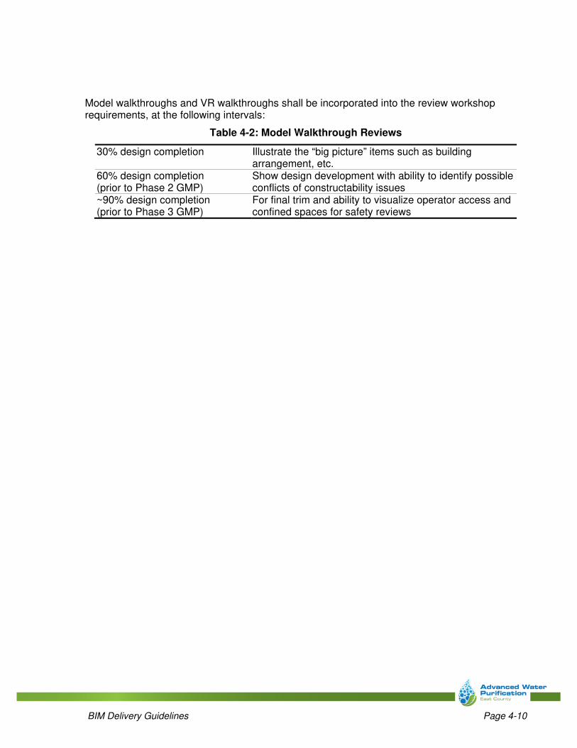
Model walkthroughs and VR walkthroughs shall be incorporated into the review workshop requirements, at the following intervals:
Table 4-2: Model Walkthrough Reviews
30% design completion Illustrate the “big picture” items such as building arrangement, etc.
60% design completion (prior to Phase 2 GMP)
Show design development with ability to identify possible conflicts of constructability issues
~90% design completion (prior to Phase 3 GMP)
For final trim and ability to visualize operator access and confined spaces for safety reviews

BIM Delivery Guidelines Page 5-1
Section 5: References
East County Advanced Water Purification Joint Powers Authority. (2020). “CAD Memorandum” (aka, CAD Standards Manual).
Computer Integrated Construction Research Program. (2011). “BIM Project Execution Planning Guide – Version 2.1.” May, The Pennsylvania State University, University Park, PA, USA.
buildingSMART alliance. (2007). “National Building Information Modeling Standard Version 1 - Part 1: Overview, Principles, and Methodologies.” National Institute of Building Sciences.
National Institute of Building Sciences. (2017). “National BIM Guide for Owners.”
BIMForum. (2019) “Level of Development (LOD) Specification for Building Information Models - Part I & Commentary.” Associated General Contractors of America.
American Institute of Architects. (2013) “G202-2013 Building Information Modeling Protocol Form.”

BIM Delivery Guidelines Page A-1
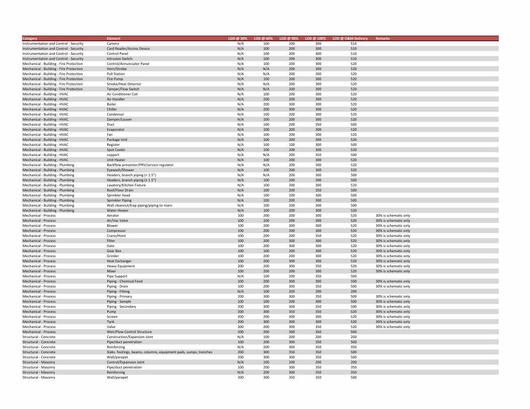
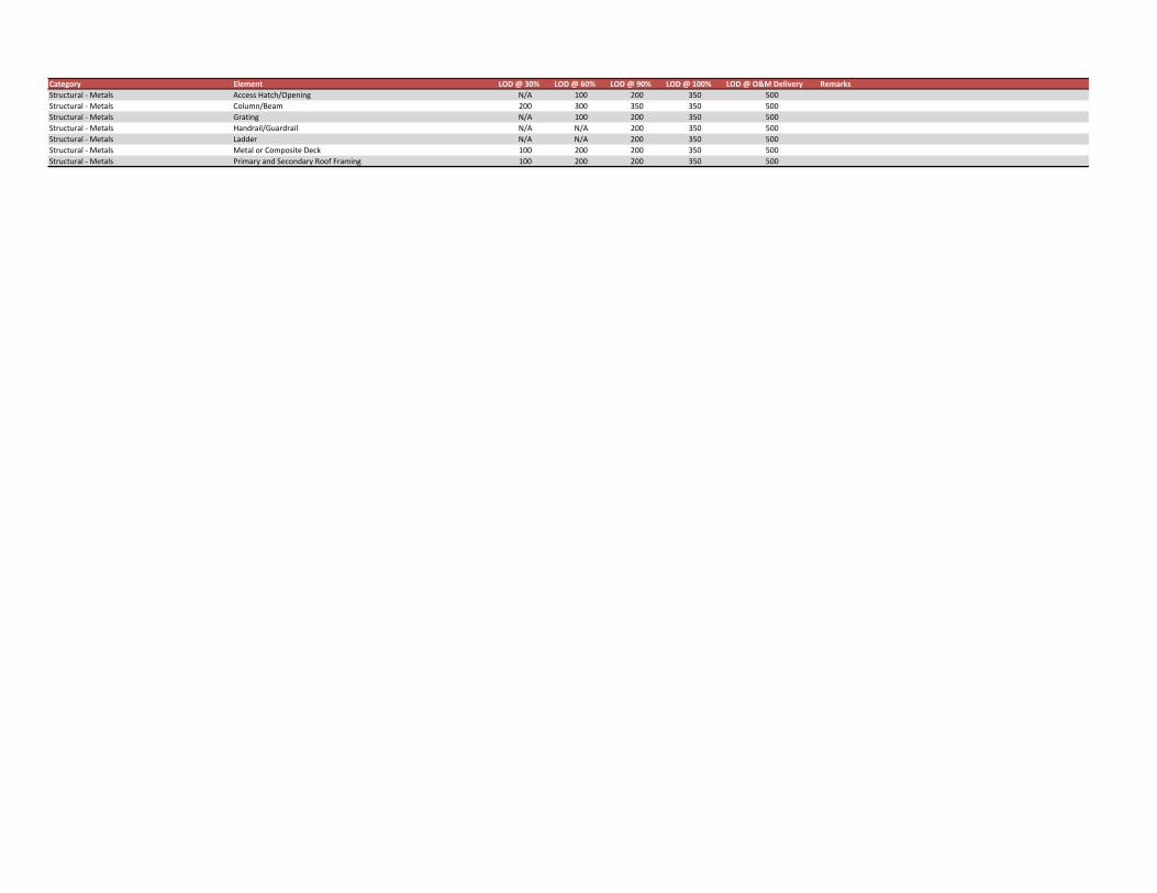
Appendix A: Model Progression Milestones
The list of model elements that follows is a comprehensive example to illustrate how the information and detail applied to each element is expected to development throughout the course of design and construction. It should be tailored for inclusion in the BIM XP which is developed for each Package, to include only, and all the element types which are expected to be included in the respective Package.
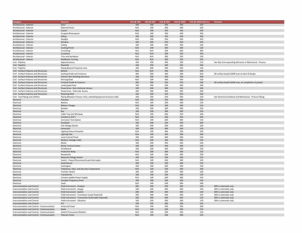
Category Element LOD @ 30% LOD @ 60% LOD @ 90% LOD @ 100% LOD @ O&M Delivery RemarksArchitectural ‐ Exterior Door 100 200 350 350 520Architectural ‐ Exterior External Finish N/A 100 300 300 520Architectural ‐ Exterior Louver N/A 200 350 350 500Architectural ‐ Exterior Scupper/Downspout N/A 100 300 350 350Architectural ‐ Exterior Siding 100 200 350 350 300Architectural ‐ Exterior Skylight N/A 200 350 350 350Architectural ‐ Exterior Window 100 200 350 350 350Architectural ‐ Interior Ceiling 100 200 350 350 520Architectural ‐ Interior Coating/Finish N/A 100 300 300 520Architectural ‐ Interior Furnishing N/A N/A 300 300 300Architectural ‐ Interior Insulation N/A N/A 300 350 350Architectural ‐ Interior Trim and Hardware N/A N/A 300 350 350Architectural ‐ Interior Wallboard, Furring N/A N/A 200 350 350Civil ‐ Pipeline Appurtenances 100 100 300 300 510 See Also Corresponding Elements in Mechanical ‐ ProcessCivil ‐ Pipeline Manhole 100 200 300 350 500Civil ‐ Pipeline Piping Beyond Property Lines 100 200 300 350 510Civil ‐ Surface Features and Structures Bollard N/A N/A 200 300 500Civil ‐ Surface Features and Structures Existing Grade and Contours 300 300 300 300 N/A 3D surface based LIDAR scan at start of designCivil ‐ Surface Features and Structures Exterior Non‐Building Structure 100 200 200 350 500Civil ‐ Surface Features and Structures Fencing/Gate N/A 100 300 350 520Civil ‐ Surface Features and Structures Finished Grade & Contours 200 300 350 350 500 3D surface based LIDAR scan, at completion of projectCivil ‐ Surface Features and Structures Landscaped Area 100 200 200 300 500Civil ‐ Surface Features and Structures Paved Area ‐ Non‐Vehicular Access 100 200 300 350 500Civil ‐ Surface Features and Structures Paved Area ‐ Vehicular Access 200 300 300 350 500Civil ‐ Surface Features and Structures Retaining Wall 100 200 350 350 500Civil ‐ Yard Piping and Utilities Piping Between Process Units, extending beyond structure walls 100 200 350 350 520 See Electrical Ductbank and Mechanical ‐ Process PipingElectrical Actuator N/A 200 350 300 520Electrical Battery N/A 100 200 300 520Electrical Battery Charger N/A 100 200 300 520Electrical Breaker 100 200 300 300 520Electrical Bus 100 200 300 300 520Electrical Cable Tray and Wireway N/A 100 200 350 500Electrical Conduit (≥ 3/4”) N/A 100 200 350 500Electrical Corrosion Test Station N/A 100 200 300 510Electrical Ductbank 100 200 350 350 500Electrical Full Voltage Starter 100 200 300 300 520Electrical Generator 100 200 300 300 520Electrical Lighting Fixture & Switch N/A 100 300 350 520Electrical Lighting Pole N/A 100 200 200 200Electrical Local Control Panel 100 200 300 300 520Electrical Medium Voltage Cable N/A 200 300 300 530Electrical Motor 100 200 350 350 520Electrical Motor Control Center 100 200 300 300 520Electrical Panelboard 100 200 300 300 520Electrical Protective Relay N/A 200 300 300 520Electrical Receptacle N/A 100 200 200 200Electrical Reduced Voltage Starter 100 200 200 300 520Electrical Switch ‐ Power/Disconnect/Load Interrupter N/A 100 200 300 520Electrical Switchboard 100 100 200 300 520Electrical Switchgear 100 100 200 300 520Electrical Telephone, Data, and Security Components N/A 100 100 200 200Electrical Transfer Switch 100 100 200 300 520Electrical Transformer 100 100 200 300 520Electrical Uninterruptible Power Supply N/A 100 200 300 520Electrical Variable Frequency Drive 100 200 200 300 520Electrical Vault N/A 100 200 300 500Instrumentation and Control Field Instrument ‐ Analysis 200 300 300 300 520 30% is schematic onlyInstrumentation and Control Field Instrument ‐ Gauge 100 200 300 300 520 30% is schematic onlyInstrumentation and Control Field Instrument ‐ Switch 200 300 300 300 520 30% is schematic onlyInstrumentation and Control Field Instrument ‐ Transducer (Loop Powered) 200 300 300 300 520 30% is schematic onlyInstrumentation and Control Field Instrument ‐ Transmitter (Externally Powered) 200 300 300 300 520 30% is schematic onlyInstrumentation and Control Field Instrument ‐ Vibration 100 200 300 300 520 30% is schematic onlyInstrumentation and Control PLC 100 200 300 300 520Instrumentation and Control ‐ Communication Antenna/Tower N/A 100 200 200 200Instrumentation and Control ‐ Communication Radio N/A 100 200 300 520Instrumentation and Control ‐ Communication Switch/Transceiver/Modem N/A 100 200 300 520Instrumentation and Control ‐ Communication Telecom Panel N/A 100 200 300 520
Category Element LOD @ 30% LOD @ 60% LOD @ 90% LOD @ 100% LOD @ O&M Delivery RemarksInstrumentation and Control ‐ Security Camera N/A 100 200 300 510Instrumentation and Control ‐ Security Card Reader/Access Device N/A 100 200 300 510Instrumentation and Control ‐ Security Control Panel N/A 100 200 300 510Instrumentation and Control ‐ Security Intrusion Switch N/A 100 200 300 510Mechanical ‐ Building ‐ Fire Protection Control/Annunciator Panel N/A 100 200 300 520Mechanical ‐ Building ‐ Fire Protection Horn/Strobe N/A N/A 200 300 520Mechanical ‐ Building ‐ Fire Protection Pull Station N/A N/A 200 300 520Mechanical ‐ Building ‐ Fire Protection Fire Pump N/A 100 200 300 520Mechanical ‐ Building ‐ Fire Protection Smoke/Heat Detector N/A N/A 200 300 520Mechanical ‐ Building ‐ Fire Protection Tamper/Flow Switch N/A N/A 200 300 520Mechanical ‐ Building ‐ HVAC Air Conditioner Coil N/A 100 200 300 520Mechanical ‐ Building ‐ HVAC Air Handler N/A 200 200 300 520Mechanical ‐ Building ‐ HVAC Boiler N/A 200 300 300 520Mechanical ‐ Building ‐ HVAC Chiller N/A 200 300 300 520Mechanical ‐ Building ‐ HVAC Condensor N/A 100 200 300 520Mechanical ‐ Building ‐ HVAC Damper/Louver N/A 100 200 300 520Mechanical ‐ Building ‐ HVAC Duct N/A 100 200 350 500Mechanical ‐ Building ‐ HVAC Evaporator N/A 100 200 300 520Mechanical ‐ Building ‐ HVAC Fan N/A 100 200 300 520Mechanical ‐ Building ‐ HVAC Package Unit N/A 100 200 300 520Mechanical ‐ Building ‐ HVAC Register N/A 100 100 300 500Mechanical ‐ Building ‐ HVAC Spot Cooler N/A 100 200 300 520Mechanical ‐ Building ‐ HVAC support N/A N/A 200 350 500Mechanical ‐ Building ‐ HVAC Unit Heater N/A 100 200 300 520Mechanical ‐ Building ‐ Plumbing Backflow preventer/PRV/service regulator N/A N/A 200 300 520Mechanical ‐ Building ‐ Plumbing Eyewash/Shower N/A 100 200 300 520Mechanical ‐ Building ‐ Plumbing Headers, branch piping (< 1.5”) N/A N/A 200 300 500Mechanical ‐ Building ‐ Plumbing Headers, branch piping (≥ 1.5”) N/A 100 200 300 500Mechanical ‐ Building ‐ Plumbing Lavatory/Kitchen Fixture N/A 100 200 300 520Mechanical ‐ Building ‐ Plumbing Roof/Floor Drain N/A 100 200 350 500Mechanical ‐ Building ‐ Plumbing Sprinkler Head N/A 100 200 300 500Mechanical ‐ Building ‐ Plumbing Sprinkler Piping N/A 100 200 300 500Mechanical ‐ Building ‐ Plumbing Wall cleanout/trap piping/piping to risers N/A 100 200 300 500Mechanical ‐ Building ‐ Plumbing Water Heater N/A 100 200 300 520Mechanical ‐ Process Aerator 100 200 200 300 520 30% is schematic onlyMechanical ‐ Process Air/Vac Valve 100 100 200 300 520 30% is schematic onlyMechanical ‐ Process Blower 100 200 300 300 520 30% is schematic onlyMechanical ‐ Process Compressor 100 200 200 300 520 30% is schematic onlyMechanical ‐ Process Crane/Hoist 100 200 200 350 520 30% is schematic onlyMechanical ‐ Process Filter 100 200 300 300 520 30% is schematic onlyMechanical ‐ Process Gate 100 200 300 300 520 30% is schematic onlyMechanical ‐ Process Gear Box 100 100 200 300 520 30% is schematic onlyMechanical ‐ Process Grinder 100 200 200 300 520 30% is schematic onlyMechanical ‐ Process Heat Exchanger 100 200 300 300 520 30% is schematic onlyMechanical ‐ Process Heavy Equipment 200 200 300 350 520 30% is schematic onlyMechanical ‐ Process Mixer 100 200 200 300 520 30% is schematic onlyMechanical ‐ Process Pipe Support N/A 100 200 350 500Mechanical ‐ Process Piping ‐ Chemical Feed 100 200 300 300 500 30% is schematic onlyMechanical ‐ Process Piping ‐ Drain 100 200 300 350 500 30% is schematic onlyMechanical ‐ Process Piping ‐ Fitting N/A 100 200 200 200Mechanical ‐ Process Piping ‐ Primary 200 300 300 350 500 30% is schematic onlyMechanical ‐ Process Piping ‐ Sample 100 100 200 300 500 30% is schematic onlyMechanical ‐ Process Piping ‐ Secondary 200 300 300 350 500 30% is schematic onlyMechanical ‐ Process Pump 200 300 350 350 520 30% is schematic onlyMechanical ‐ Process Screen 200 200 300 300 520 30% is schematic onlyMechanical ‐ Process Tank 200 300 300 300 520 30% is schematic onlyMechanical ‐ Process Valve 200 200 300 350 520 30% is schematic onlyMechanical ‐ Process Weir/Flow Control Structure 200 200 300 350 500Structural ‐ Concrete Construction/Expansion Joint N/A 100 200 200 200Structural ‐ Concrete Pipe/duct penetration 100 200 300 350 500Structural ‐ Concrete Reinforcing N/A 200 300 350 350Structural ‐ Concrete Slabs. footings, beams, columns, equipment pads, sumps, trenches 200 300 350 350 500Structural ‐ Concrete Wall/parapet 200 300 300 350 500Structural ‐ Masonry Control/Expansion Joint N/A 100 200 200 200Structural ‐ Masonry Pipe/duct penetration 100 200 300 350 350Structural ‐ Masonry Reinforcing N/A 200 300 350 350Structural ‐ Masonry Wall/parapet 200 300 350 350 500
Category Element LOD @ 30% LOD @ 60% LOD @ 90% LOD @ 100% LOD @ O&M Delivery RemarksStructural ‐ Metals Access Hatch/Opening N/A 100 200 350 500Structural ‐ Metals Column/Beam 200 300 350 350 500Structural ‐ Metals Grating N/A 100 200 350 500Structural ‐ Metals Handrail/Guardrail N/A N/A 200 350 500Structural ‐ Metals Ladder N/A N/A 200 350 500Structural ‐ Metals Metal or Composite Deck 100 200 200 350 500Structural ‐ Metals Primary and Secondary Roof Framing 100 200 200 350 500