
Bilstein case study KRANBAU Kranbau Köthen GmbH … · Bilstein case study, Kranbau Köthen GmbH...
10
02/09/2016, Heiner Witke Bilstein case study Kranbau Köthen GmbH KÖTHEN KRANBAU
Transcript of Bilstein case study KRANBAU Kranbau Köthen GmbH … · Bilstein case study, Kranbau Köthen GmbH...
02/09/2016, Heiner Witke
Bilstein case studyKranbau Köthen GmbH KÖTHEN
KRANBAU
Bilstein case study, Kranbau Köthen GmbH KÖTHENKRANBAU
Page 2
Whenever possible, the annealing system operates in automatic modeIn conjunction with its partners, Kranbau Köthen delivers crane systems which are tailored to its customers needs – from a sin-gle source.
Increasingly complex manufacturing, warehousing and commissioning systems present crane manufacturers with greater technological challenges. The position occupied by traditional metal construction and engineering systems in this area is becoming less and less significant and classic crane manufacturers are increasingly re-quired to work across heterogeneous disciplines. Any company wishing to keep in sight an increase in productivity and efficiency in client business must respond to the need to develop intelligent systems and software solutions. The customer determines the requirements: they want faster, more secure, efficient and automated systems.
Cranes are being more closely integrated into production
Intelligent lifting apparatus and automatic cranes – everybody‘s talking about digitisation. Here at Kranbau Köthen, this hasn‘t passed us by either. The fact is that market requirements are changing. The benefits of crane automation are clear to see: increased client productivity, reduced damage, less wear, lower costs, improved quality standards thanks to automated processes, time savings and reduced space requirements.
Fully automated coil transport using crane technology
Bilstein Group, an international cold rolled strip manufacturer, operates one of the most modern annealing plants using crane technology at its Hagen-Hohenlimburg location. The plant‘s purpose is to anneal hot- and cold-rolled steel strip coils with coil weights of up to 30 t, outer diameters of up to 2,000 mm and collar widths of up to 1,350 mm. The coils, which are supplied by their own rolling mill, are identified and are automatically pre-batched.
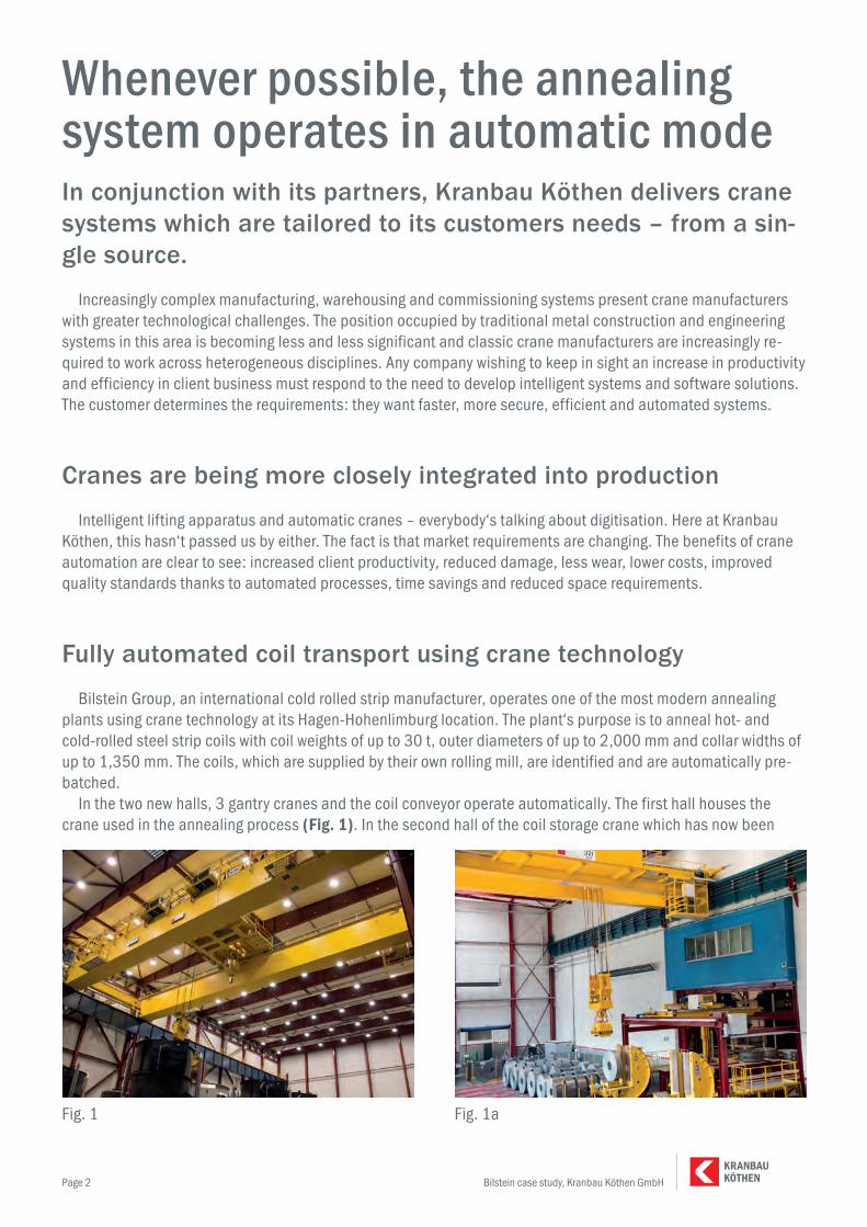
In the two new halls, 3 gantry cranes and the coil conveyor operate automatically. The first hall houses the crane used in the annealing process (Fig. 1). In the second hall of the coil storage crane which has now been
Fig. 1 Fig. 1a
Bilstein case study, Kranbau Köthen GmbH KÖTHENKRANBAU
Page 3
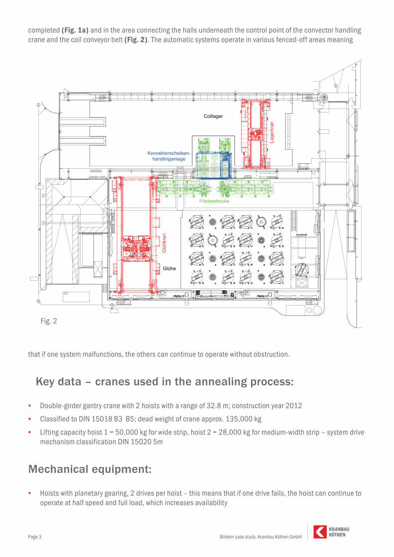
completed (Fig. 1a) and in the area connecting the halls underneath the control point of the convector handling crane and the coil conveyor belt (Fig. 2). The automatic systems operate in various fenced-off areas meaning
that if one system malfunctions, the others can continue to operate without obstruction.
Key data – cranes used in the annealing process:
▪ Double-girder gantry crane with 2 hoists with a range of 32.8 m; construction year 2012
▪ Classified to DIN 15018 B3 B5; dead weight of crane approx. 135,000 kg
▪ Lifting capacity hoist 1 = 50,000 kg for wide strip, hoist 2 = 28,000 kg for medium-width strip – system drive mechanism classification DIN 15020 5m
Mechanical equipment:
▪ Hoists with planetary gearing, 2 drives per hoist – this means that if one drive fails, the hoist can continue to operate at half speed and full load, which increases availability
Fig. 2

Bilstein case study, Kranbau Köthen GmbH KÖTHENKRANBAU
Page 4
▪ Crane equipment adheres to DIN EN 14492-2, as pressurised hydrogen lines are run overhead
▪ Redundant rope drive and emergency grippers act on the flanged pulleys of the rope drums
▪ Crane is for use in ambient temperatures of up to + 70°C
▪ The crane is equipped with fire extinguishing equipment for the control room inside the crane bridge
▪ Control room in the bridge (Fig. 10) is insulated and air-conditioned, the air-conditioning system includes redundancy
▪ Dust extraction on the crane rails
▪ The crane and cross-travel drives are of a conventional design, drives with joint shafts, transmission, sepa-rate brakes, coupling and standard engines are designed to smelting works standards
▪ Lower blocks with motor-driven load-pick up and forged lugs for zero-play
▪ rotation
▪ Constructive integration of the gripper (supplied by Bönnhoff), meaning that coils and convectors as well as heating, cooling and protective caps can be picked up without human intervention.
Electro-technical equipment:
▪ Unrestricted manual operation
▪ Positioning guide in manual mode including camera monitoring
▪ Automatic operation in the safety barrier area
▪ Safety technology to performance level “d”
▪ Safety-oriented position tracking of crane travel, cross travel, hoists
▪ 2 safety transmitters per hoist for speed monitoring
▪ Safety barrier with a total of 9 safety doors, security locks and various safety areas
▪ All end positions for travel and overload are equipped with safety-oriented cut-off points
▪ Position sensors on both sides of crane travel, cross-travel on one side to take into account potential slewing of the crane when positioning – toothed belt design (Fig. 9).
▪ Camera-led pendulum damping system, optimised for various load centres, gripper equipment with various
Fig. 10 Fig. 9
Bilstein case study, Kranbau Köthen GmbH KÖTHENKRANBAU
Page 5
sensors, cap recognition, coil, convectors, distance measurement, gripper height, RFID cap number recogni-tion – distance measurement
▪ Interfaces to LOI (supplier of the annealing line) and the Bilstein production data acquisition system
▪ Integrated warehouse management for seamless material tracking in both manual and automatic mode
▪ Visualisation of actual stock inventory
▪ Monitoring of warehouse standards (stacking height, storage space feasibility)
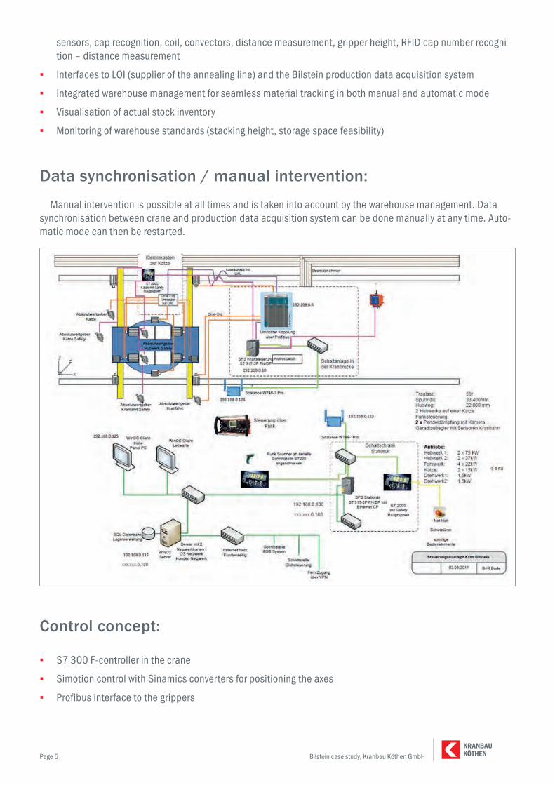
Data synchronisation / manual intervention:
Manual intervention is possible at all times and is taken into account by the warehouse management. Data synchronisation between crane and production data acquisition system can be done manually at any time. Auto-matic mode can then be restarted.
Control concept:
▪ S7 300 F-controller in the crane
▪ Simotion control with Sinamics converters for positioning the axes
▪ Profibus interface to the grippers
Bilstein case study, Kranbau Köthen GmbH KÖTHENKRANBAU
Page 6
▪ S7 300 F controller in the static control unit
▪ Coupling of the two control units via a WLAN connection
▪ WinCC server/client for visualisation purposes
▪ Microsoft SQL server for warehouse management
▪ Industrial PC with touch panel monitor for local operation
Key data – automated coil storage:
▪ Double-girder gantry crane with one hoist with 19.55m range precision
▪ Construction year 2015
▪ Classified to DIN 15018 B3 B5; dead weight of crane approx. 75,000 kg
▪ Hoist load capacity 45,000 kg, operating load of the broad strip magnet 32,000 kg
▪ System drive classification DIN 15020 4m
▪ Control room in an insulated, air-conditioned e-container on the crane
▪ Lower block with rotating mechanism and fixed permanently energized electromagnetic magnet
Equivalent electro-technical equipment to the crane used within the annealing system
Key data – convector handling crane:
▪ Double-girder gantry crane with one hoist with range precision of 7.0 m
▪ Construction year 2016
▪ Classified to DIN 15018 H3 B4; dead weight of crane approx. 11,000 kg
▪ Hoist load capacity 5,000 kg, operating load of the convector gripper 1,000 kg
▪ System drive classification DIN 15020 4m
▪ Telescopic guidance for precise positioning with the convector gripper
▪ Static and level control system in the conveyor belt area
Equivalent electro-technical equipment to the crane used within the annealing system
Key data – coil conveyor line:
The coil conveyor line for medium and broad strips consists of the following main components:
▪ 2 coil revolving tables forming a welded frame construction with drive unit, tilting frame with moveable V-block table in order to guarantee the coil position even with various coil widths
▪ 4 coil cars to transport the coils between the revolving tables and fixed positions to lay down/remove the con-

Bilstein case study, Kranbau Köthen GmbH KÖTHENKRANBAU
Page 7
vectors and coils in the annealing system
▪ 4 coil supports for the coil hall area to the annealing plant; annealing hall.
▪ The coil cars operate within the coil support construction.
▪ (Fig. 11) can be principally used as a representation
The controls of the coil conveyor line are integrated into the overall functional process.
Description of an annealing process:
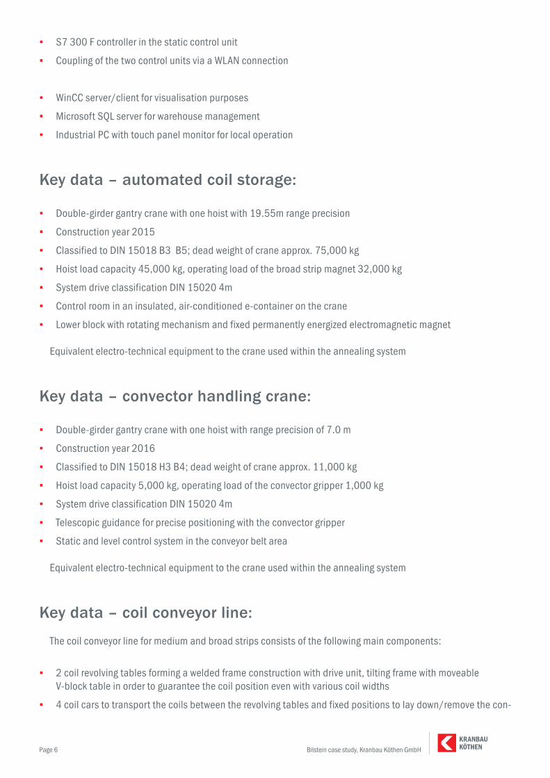
▪ Coils are supplied manually in the coil storage hall using a fork-lift, storage area 1–3, (Fig. 3)
▪ Here, the coils are scanned by the operator. The crane computer (LVS) has previously received the coil data from the Bilstein production data acquisition system. The scanned data is used to check whether the coil can be stored.
▪ The coil crane then picks the coil up automatically and stores it in the buffer storage area. Here, the coil data, measurement and crane weights undergo a plausibility check. Taking storage restrictions into account, the optimal storage place is determined and the coil is stored. (Fig. 4).
▪ Using the production data acquisition system, the annealing plant sends a request for the next annealing pro-cess. The coil storage crane collects the selected coils in a precise manner out of the buffer storage area and deposits them on the V-block on the revolving table. Permanently energised electromagnetic magnets permit
Fig. 11
Bilstein case study, Kranbau Köthen GmbH KÖTHENKRANBAU
Page 8
the coil storage crane to bear the load.
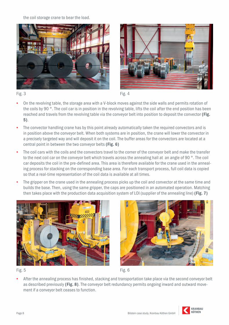
▪ On the revolving table, the storage area with a V-block moves against the side walls and permits rotation of the coils by 90 °. The coil car is in position in the revolving table, lifts the coil after the end position has been reached and travels from the revolving table via the conveyor belt into position to deposit the convector (Fig. 5).
▪ The convector handling crane has by this point already automatically taken the required convectors and is in position above the conveyor belt. When both systems are in position, the crane will lower the convector in a precisely targeted way and will deposit it on the coil. The buffer areas for the convectors are located at a central point in between the two conveyor belts (Fig. 6)
▪ The coil cars with the coils and the convectors travel to the corner of the conveyor belt and make the transfer to the next coil car on the conveyor belt which travels across the annealing hall at an angle of 90 °. The coil car deposits the coil in the pre-defined area. This area is therefore available for the crane used in the anneal-ing process for stacking on the corresponding base area. For each transport process, full coil data is copied so that a real-time representation of the coil data is available at all times.
▪ The gripper on the crane used in the annealing process picks up the coil and convector at the same time and builds the base. Then, using the same gripper, the caps are positioned in an automated operation. Matching then takes place with the production data acquisition system of LOI (supplier of the annealing line) (Fig. 7)
▪ After the annealing process has finished, stacking and transportation take place via the second conveyor belt as described previously (Fig. 8). The conveyor belt redundancy permits ongoing inward and outward move-ment if a conveyor belt ceases to function.
Fig. 3 Fig. 4
Fig. 5 Fig. 6

Bilstein case study, Kranbau Köthen GmbH KÖTHENKRANBAU
Page 9
▪ Once the 2nd revolving table has put the coil in the correct position for the coil storage crane, the coil storage crane will take over and will either place it in the buffer storage area in between or in storage areas 4–6. This concludes the automated process and the coil is discharged for further processing on a forklift. The data is provided to the Bilstein production data acquisition system.
Distributed, zero-defect automation:
Kranbau Köthen consults external experts when dealing with such specialised areas. The company Bormann and Reinhold designed the distributed automation concept based on two zero-defect Simatic S7-300F systems to meet the specific requirements of unmanned crane operations. An F-controller is installed in the central switchboard on the ground which uses standard, fail-safe peripheral components to manage the customary signals throughout the process as well as the safety-related signals for guard doors, photoelectric sensors and emergency buttons.
Radio control for manual operation is also linked to this. Data exchange takes place using the Scada-level – Simatic WinCC server in the central server room as well as WinCC-Clients in the hall and the control room as well as using the production data acquisition system and annealing process management system. In addition, the on-site controls function as an interface for remote access to the plant via VPN (Virtual Private Network).
WLAN-Access-Point Scalance W788-1 Pro and an IWLAN-Client-Module Scalance W746-1 Pro create the link between fail-safe controls on the ground and the cranes. By means of the wireless connection, error-free pro-cess- and safety-related signals are transmitted and the crane is restored to a secure state if malfunctions occur, meaning that the Performance Level PL d in accordance with EN ISO 13849-1 is achieved.
As temperatures of up to 75°C are reached through the annealing bases, all of the automation technology on the crane used in the annealing process is installed in an insulated and air-conditioned control room in a bridge girder. This is also the case for the Motion Control System Simotion D435 which is part of the installation tech-nology of the modular drive system Sinamics S120. This linked to the crane control system using Profibus and coordinates the transportation movements in the main axles. In order to prevent inclined positions on the crane track and resulting inaccuracies or problems, track measurement on both sides of the crane direction is operated using an absolute value track measurement system and the drives on the right and left sides of the chassis are operated using master-slave controls. A virtual master manages these synchronisation controls, which coordi-nates the movement of the machinery in its entirety in the motion controller. As positioning axes, crabs and hoists are equipped with external sensors. Thus, the tolerances which were initially described are adhered to.
Fig. 7 © Bilstein Fig. 8 © Bilstein
Bilstein case study, Kranbau Köthen GmbH KÖTHENKRANBAU
Page 10
The movements are powered using standard motors, four of which are located in the crane chassis, two on the crabs and two each in the hoists. The absolute value motor encoders are linked to the control units of the motion control system via the digital system bus DriveCliq; this takes place by means of a fibre optic converter on the crabs and the hoists. There are also additional security rotation- and position encoders to monitor the program-mable protective zones in the automated areas. These are linked to the zero-defect crane control system via Profibus and the Profisafe protocol. The security-oriented shutdown function in case of malfunction is simplified through the use of the STO (Safe Torque Off) security function in the drive system. With the software limit switches in the PLC programme, three supervision levels are created in order to safely prevent protection faults and colli-sions.
A pendulum movement regulation system (pendulum damping system) ensures the three main axes are only affected by minimal pendulum movements when accelerating and braking. Positioning accuracy of +/- 20 mm can be achieved in this way. Loads can be handled with significantly more speed, thereby achieving optimised turnover rates.
The implemented automation and security concept was presented to DEKRA (German Motor Vehicle Inspection Association) for certification and was granted final approval at the first attempt. Bilstein is also fully satisfied with the implementation of the system as a system operator. As a result of the complete automation of the crane operation, the annealing bases can be arranged closer to one another than ever before, thereby optimising coil storage, saving space and money. The advantages of automation in annealing was reason enough for Bilstein to equip the coil storage hall with convector handling apparatus too.
We have also achieved a greater degree of efficiency, emphasised Helmut Mühlnickel, Head of Plant and Process Technology at Bilstein Service GmbH. The precision of the automated system has led to the complete elimination of damage to plant components. Acceptance has also been gained from users; they also make use of the automation technology whenever possible.
About Kranbau Köthen
Kranbau Köthen GmbH is a medium-sized company that specialises in special-purpose, process and auto-matic cranes. We have been manufacturing complete, customised crane systems for use around the world at our Köthen site in Saxony-Anhalt since we were founded in 1934. We combine traditional company values such as honesty, courtesy and esteem with modern ways of working and thinking, and with an eye to the future. We work as partners and in close cooperation with our customers thanks to our excellent consultation services and solu-tion-based thinking.
Georgsmarienhütte, 02/09/2016
p.p. Heiner WitkeKranbau Köthen GmbH


