
BIG-IP Administrator Guide - F5 Networks · BIG-IP® Administrator Guide version ... Product...
298
BIG-IP ® Administrator Guide version 4.0 MAN-0034-00
Transcript of BIG-IP Administrator Guide - F5 Networks · BIG-IP® Administrator Guide version ... Product...

BIG-IP® Administrator Guide
version 4.0
MAN-0034-00

Service and Support Information
Product VersionThis manual applies to version 4.0 of the BIG-IP® Controller.
Obtaining Technical Support
Contacting F5 Networks
Web tech.f5.com
Phone (206) 272-6888
Fax (206) 272-6802
Email (support issues)
Email (suggestions) [email protected]
Web www.f5.com
Toll-free phone (888) 961-7242
Corporate phone (206) 272-5555
Fax (206) 272-5556
Email [email protected]
Mailing Address 401 Elliott Avenue WestSeattle, Washington 98119
Administrator Guide i

Legal Notices
Copyright
F5 Networks, Inc. (F5) believes the information it furnishes to be accurate and reliable. However, F5 assumes no responsibility for the use of this information, nor any infringement of patents or other rights of third parties which may result from its use. No license is granted by implication or otherwise under any patent, copyright, or other intellectual property right of F5 except as specifically described herein. F5 reserves the right to change specifications at any time without notice.
Copyright 1997-2001, F5 Networks, Inc. All rights reserved.
Trademarks
F5, BIG-IP, 3-DNS, SEE-IT, and GLOBAL-SITE are registered trademarks of F5 Networks, Inc. EDGE-FX, iControl, and FireGuard are trademarks of F5 Networks, Inc. Other product and company names are registered trademarks or trademarks of their respective holders.
Export Regulation Notice
The BIG-IP® Controller may include cryptographic software. Under the Export Administration Act, the United States government may consider it a criminal offense to export this BIG-IP® Controller from the United States.
Export Warning
This is a Class A product. In a domestic environment this product may cause radio interference in which case the user may be required to take adequate measures.
FCC Compliance
This equipment generates, uses, and may emit radio frequency energy. The equipment has been type tested and found to comply with the limits for a Class A digital device pursuant to Part 15 of FCC rules, which are designed to provide reasonable protection against such radio frequency interference.
Operation of this equipment in a residential area may cause interference, in which case the user at his own expense will be required to take whatever measures may be required to correct the interference.
Any modifications to this device, unless expressly approved by the manufacturer, can void the user's authority to operate this equipment under part 15 of the FCC rules.
Canadian Regulatory Compliance
This class A digital apparatus complies with Canadian I CES-003.
Standards Compliance
The product conforms to ANSI/UL Std 1950 and Certified to CAN/CSA Std. C22.2 No. 950.
ii BIG-IP® Controller 4.0

Acknowledgments
This product includes software developed by the University of California, Berkeley and its contributors.
This product includes software developed by the Computer Systems Engineering Group at the Lawrence Berkeley Laboratory.
This product includes software developed by the NetBSD Foundation, Inc. and its contributors.
This product includes software developed by Christopher G. Demetriou for the NetBSD Project.
This product includes software developed by Adam Glass.
This product includes software developed by Christian E. Hopps.
This product includes software developed by Dean Huxley.
This product includes software developed by John Kohl.
This product includes software developed by Paul Kranenburg.
This product includes software developed by Terrence R. Lambert.
This product includes software developed by Philip A. Nelson.
This product includes software developed by Herb Peyerl.
This product includes software developed by Jochen Pohl for the NetBSD Project.
This product includes software developed by Chris Provenzano.
This product includes software developed by Theo de Raadt.
This product includes software developed by David Muir Sharnoff.
This product includes software developed by SigmaSoft, Th. Lockert.
This product includes software developed for the NetBSD Project by Jason R. Thorpe.
This product includes software developed by Jason R. Thorpe for And Communications, http://www.and.com.
This product includes software developed for the NetBSD Project by Frank Van der Linden.
This product includes software developed for the NetBSD Project by John M. Vinopal.
This product includes software developed by Christos Zoulas.
This product includes software developed by Charles Hannum.
This product includes software developed by Charles Hannum, by the University of Vermont and State Agricultural College and Garrett A. Wollman, by William F. Jolitz, and by the University of California, Berkeley, Lawrence Berkeley Laboratory, and its contributors.
This product includes software developed by the University of Vermont and State Agricultural College and Garrett A. Wollman.
In the following statement, "This software" refers to the Mitsumi CD-ROM driver: This software was developed by Holger Veit and Brian Moore for use with "386BSD" and similar operating systems. "Similar operating systems" includes mainly non-profit oriented systems for research and education, including but not restricted to "NetBSD," "FreeBSD," "Mach" (by CMU).
In the following statement, "This software" refers to the parallel port driver: This software is a component of "386BSD" developed by William F. Jolitz, TeleMuse.
Administrator Guide iii

This product includes software developed by the Apache Group for use in the Apache HTTP server project (http://www.apache.org/).
This product includes software developed by Darren Reed. (© 1993-1998 by Darren Reed).
This product includes software licensed from Richard H. Porter under the GNU Library General Public License (© 1998, Red Hat Software), www.gnu.org/copyleft/lgpl.html.
This product includes the standard version of Perl software licensed under the Perl Artistic License (© 1997, 1998 Tom Christiansen and Nathan Torkington). All rights reserved. You may find the most current standard version of Perl at http://www.perl.com.
iv BIG-IP® Controller 4.0

Table of Contents

Table of Contents
IntroductionGetting started ....................................................................................................... Intro-1
Choosing a configuration tool ................................................................... Intro-1Using the Administrator Kit ............................................................................... Intro-2
Stylistic conventions .................................................................................... Intro-3Finding additional help and technical support resources .................... Intro-6
What’s new in version 4.0 ................................................................................... Intro-73-DNS on the BIG-IP Controller ............................................................. Intro-7OneConnect™ content switching with HTTP Keep-Alives .............. Intro-7Bridging and Layer 2 forwarding ............................................................... Intro-7HTTP Redirect pool property .................................................................. Intro-8Load balance any IP protocol .................................................................... Intro-8Link aggregation and fail-over .................................................................... Intro-8On-the-fly content converter .................................................................... Intro-8SNAT automap feature ............................................................................... Intro-9Health monitors ........................................................................................... Intro-9Performance monitors ................................................................................ Intro-9Default controller configuration ............................................................... Intro-9Web-based Configuration utility enhancements .................................Intro-10
Learning more about the BIG-IP Controller product family .....................Intro-10
1BIG-IP Controller Overview
Introduction ...................................................................................................................1-1User interface .......................................................................................................1-1
A basic configuration ...................................................................................................1-3Configuring objects and object properties .............................................................1-5
Load balancing modes ........................................................................................1-7BIG-IP Controllers and intranets ..............................................................................1-8
Bidirectional load balancing ...............................................................................1-9Cache control .............................................................................................................1-11SSL acceleration ..........................................................................................................1-12Content conversion ...................................................................................................1-12VLANs ...........................................................................................................................1-12
Link aggregation and link failover ..................................................................1-13Configuring redundant BIG-IP Controller pairs ..................................................1-13Making hidden nodes accessible ..............................................................................1-14
Forwarding ..........................................................................................................1-14Address translation ...........................................................................................1-14
Monitoring and administration ................................................................................1-15Health monitors ................................................................................................1-15Statistical monitoring ........................................................................................1-15
Administrator Guide vii

Table of Contents
2Basic Web Site and E-Commerce Configuration
Working with a basic web site and e-commerce configuration ........................2-1Configuring a basic e-commerce site .......................................................................2-2
Defining the pools ...............................................................................................2-2Defining the virtual servers ...............................................................................2-4
Additional configuration options ..............................................................................2-5
3Installing a BIG-IP Controller without Changing the IP Network
Installing a BIG-IP Controller without changing IP networks ............................3-1Configuring the controller for the same IP network ..................................3-2
Additional configuration options ..............................................................................3-8
4A Simple Intranet Configuration
Working with a simple intranet configuration .......................................................4-1Creating the simple intranet configuration ...................................................4-3Defining the pools ...............................................................................................4-3Defining the virtual servers ...............................................................................4-4
Additional configuration options ..............................................................................4-5
5Load Balancing ISPs
Using ISP load balancing ..............................................................................................5-1Configuring ISP load balancing ..........................................................................5-2
Configuring network address translation on routers ..........................................5-4Enabling service 80 and service 443 .........................................................................5-6Additional configuration options ..............................................................................5-6
6Load Balancing VPNs
Working with VPN load balancing ...........................................................................6-1Configuring VPN load balancing .......................................................................6-2
Using VPN and router load balancing ......................................................................6-5Configuring virtual servers for VPN and router load balancing ...............6-5Configuring VPN and router load balancing .................................................6-7
Additional configuration options ............................................................................6-12
viii BIG-IP® Controller 4.0
Table of Contents
7Using IPSEC with VPN Gateways
Configuring load balancing between VPN gateways .............................................7-1Configuring IPSEC load balancing ....................................................................7-3
The VPN sandwich configuration with IPSEC ........................................................7-6Additional configuration options ..............................................................................7-9
8Configuring an SSL Accelerator
Introducing the SSL Accelerator ...............................................................................8-1Configuring the SSL Accelerator ..............................................................................8-2
Generating a key and obtaining a certificate .................................................8-3Installing certificates from the certificate authority (CA) ..........................8-9Creating a pool for the HTTP servers .........................................................8-11Creating an HTTP virtual server ...................................................................8-12Creating an SSL gateway ..................................................................................8-13
Introducing the SSL accelerator scalable configuration .....................................8-16Creating the scalable SSL accelerator configuration .................................8-18Configuring the BIG-IP Controller that load balances the SSL accelerators ........................................................................................................8-18Configuring the SSL accelerators ...................................................................8-23
Additional configuration options ............................................................................8-24
9Balancing Two-Way Traffic Across Firewalls
Introducing two-way firewall load balancing ..........................................................9-1Configuring two-way firewall load balancing ..........................................................9-3Configuring routing to the internal network .........................................................9-3Creating pools for firewalls and servers .................................................................9-3
Creating a pool for outside firewall interfaces .............................................9-4Creating a pool for inside firewall interfaces ................................................9-5Creating a pool for servers ...............................................................................9-6
Creating virtual servers for inbound traffic ............................................................9-7Creating a network virtual server to load balance the firewalls ..............9-7Enhancing security for this configuration .......................................................9-9Creating a standard virtual server to load balance intranet servers .......9-9
Creating virtual servers for outbound traffic .......................................................9-10Creating a wildcard virtual server for balancing traffic to the firewalls ................................................................................................................9-11Creating a forwarding wildcard virtual server to forward traffic to the Internet ...................................................................................................9-12
Administrator Guide ix
Table of Contents
Configuring administrative routing .........................................................................9-14Additional configuration options ............................................................................9-14
10Load Balancing a Cache Array for Local Server Acceleration
Introducing local server acceleration .....................................................................10-1Maximizing memory or processing power ..................................................10-2Using the configuration diagram ....................................................................10-3
Configuring local acceleration .................................................................................10-3Creating pools .............................................................................................................10-4
Creating a pool for the cache servers ..........................................................10-5Creating a pool for the origin server ...........................................................10-6Creating a pool for hot content ....................................................................10-7
Creating a cache rule .................................................................................................10-8Using a cacheable content expression .........................................................10-9Setting content demand status .................................................................... 10-11
Creating a virtual server ........................................................................................ 10-12Configuring for intelligent cache population ..................................................... 10-13
Configuring a SNAT ....................................................................................... 10-14Additional configuration options ......................................................................... 10-15
11Load Balancing a Cache Array for Remote Server Acceleration
Introducing remote server acceleration ...............................................................11-1Maximizing memory or processing power ..................................................11-3
Configuring remote server acceleration ...............................................................11-3Creating pools .............................................................................................................11-4
Creating a pool for the cache servers ..........................................................11-5Creating a pool for the origin server ...........................................................11-6Creating a pool for hot content ....................................................................11-7
Creating a cache rule .................................................................................................11-8Working with a cacheable content expression ..........................................11-8Understanding content demand status ..................................................... 11-11
Creating a virtual server ........................................................................................ 11-12Configuring for intelligent cache population ..................................................... 11-13
Configuring a SNAT ....................................................................................... 11-14Configuring a SNAT automap for bounceback ....................................... 11-15
Additional configuration options ......................................................................... 11-16
x BIG-IP® Controller 4.0

Table of Contents
12Configuring Forward Proxy Caching
Introducing forward proxy caching ........................................................................12-1Maximizing memory or processing power ..................................................12-2Using the configuration diagram ....................................................................12-2
Configuring forward proxy caching ........................................................................12-3Creating pools .............................................................................................................12-4
Creating a pool for the cache servers ..........................................................12-5Creating a pool for the origin server ...........................................................12-6Creating a pool for hot content ....................................................................12-7
Creating a cache rule .................................................................................................12-8Working with a cacheable content expression ..........................................12-8Understanding content demand status ..................................................... 12-10
Creating a virtual server ........................................................................................ 12-12Additional configuration options ......................................................................... 12-13
13Configuring a Content Converter
Introducing the content converter .........................................................................13-1Configuring the content converter ........................................................................13-3
Configuring the on-the-fly conversion software ........................................13-3Creating the load balancing pool ...................................................................13-4Creating the virtual server ..............................................................................13-5Creating a content converter gateway using the Configuration utility .....................................................................................................................13-6Enabling, disabling, or deleting a content converter gateway .................13-7Displaying the configuration for a content converter gateway from the command line ....................................................................................13-8
Additional configuration options ............................................................................13-9
14Hosting Multiple Sites
Introducing multiple site hosting .............................................................................14-1Configuring multiple site hosting ............................................................................14-1
Creating VLAN tags ..........................................................................................14-2Creating the server pools to load balance ..................................................14-3Creating the virtual server to load balance the web servers ..................14-4
Additional configuration options ............................................................................14-4
Administrator Guide xi

Table of Contents
15Using Link Aggregation with Tagged VLANs
Introducing link aggregation with tagged VLANs ................................................15-1Using the two-network aggregated tagged VLAN topology ............................15-1
Configuring the two-network topology .......................................................15-2Aggregating the links .........................................................................................15-3Creating VLAN tags ..........................................................................................15-4Creating the pool of web servers to load balance ....................................15-5Creating the virtual server to load balance the web servers ..................15-5
Using the one-network aggregated tagged VLAN topology ............................15-6Configuring the one-network topology .......................................................15-7Creating a VLAN group ...................................................................................15-8Creating a self IP for the VLAN group .........................................................15-9
Additional configuration options ............................................................................15-9
16One IP Network Topologies
Introducing the one-IP network topology ............................................................16-1Setting up a one-IP network topology with one interface ................................16-2
Defining the pools for an additional Internet connection ........................16-2Defining the virtual server ...............................................................................16-3Configuring the client SNAT ..........................................................................16-3
Additional configuration options ............................................................................16-4
17nPath routing
Introducing nPath routing .........................................................................................17-1Defining a server pool for nPATH routing .................................................17-3Defining a virtual server with address translation disabled .....................17-4Configuring the virtual server on the content server loopback interface ...............................................................................................................17-5Setting the route for inbound traffic .............................................................17-5Setting the return route ..................................................................................17-5Setting the idle connection time-out ............................................................17-6
Additional configuration options ............................................................................17-7
xii BIG-IP® Controller 4.0

Table of Contents
18Monitoring and Administration
Monitoring and administration utilities ..................................................................18-1Using the bigpipe utility as a monitoring tool ......................................................18-2
Monitoring the BIG-IP Controller .................................................................18-2Monitoring virtual servers, virtual addresses and services ................... 18-10Monitoring nodes and node addresses ..................................................... 18-12Monitoring NATs ........................................................................................... 18-13Monitoring SNATs ......................................................................................... 18-14Viewing the status of the interface cards ................................................. 18-14
Using the Configuration utility for administration and monitoring ............. 18-15Adding a user .................................................................................................. 18-15Customizing the Configuration utility ....................................................... 18-15Configuring SNMP .......................................................................................... 18-16
Working with the BIG/top utility ........................................................................ 18-16Using BIG/top command options ............................................................... 18-17Using runtime commands in BIG/top ........................................................ 18-17
Working with the Syslog utility ............................................................................ 18-18Sample log messages ...................................................................................... 18-18
Removing and returning items to service .......................................................... 18-19Removing the BIG-IP Controller from service ........................................ 18-20Removing individual virtual servers, virtual addresses, and ports from service .......................................................................................... 18-21Removing individual nodes and node addresses from service ............. 18-22Viewing the currently defined virtual servers and nodes ...................... 18-22
Viewing system statistics and log files ................................................................. 18-22Viewing system statistics .............................................................................. 18-23Viewing log files .............................................................................................. 18-23
Printing the connection table ................................................................................ 18-24Changing passwords ............................................................................................... 18-24
Changing passwords and adding new user IDs for the web-based Configuration utility .................................................................. 18-24
Working with the BIG/db database .................................................................... 18-26Using the bigpipe db command ................................................................... 18-26
Working with the BIG/stat utility ........................................................................ 18-28
19Configuring SNMP
Working with SNMP .................................................................................................19-1Getting started with SNMP ......................................................................................19-2
Downloading the MIBs .....................................................................................19-2Allowing access ..................................................................................................19-3
Administrator Guide xiii

Table of Contents
Configuring SNMP settings .......................................................................................19-4Downloading the MIBs .....................................................................................19-5/etc/hosts.deny ...................................................................................................19-6/etc/hosts.allow ..................................................................................................19-6/etc/snmpd.conf ..................................................................................................19-8/etc/snmptrap.conf ......................................................................................... 19-11Syslog ................................................................................................................. 19-12Enable the SNMP port .................................................................................. 19-12
Glossary
Index
xiv BIG-IP® Controller 4.0

Introduction
• Getting started
• Using the Administrator Kit
• What’s new in version 4.0
• Learning more about the BIG-IP Controller product family

Introduction
Getting startedBefore you start installing the controller, we recommend that you browse the BIG-IP Administrator Guide and find the load balancing solution that most closely addresses your needs. If the BIG-IP Controller is running the 3-DNS software module, you may also want to browse the 3-DNS Administrator Guide to find a wide area load balancing solution. Briefly review the basic configuration tasks and the few pieces of information, such as IP addresses and host names, that you should gather in preparation for completing the tasks.
Once you find your solution and gather the necessary network information, turn back to the Installation Guide for hardware installation instructions, and then return to the Administrator Guide to follow the steps for setting up your chosen solution.
Choosing a configuration tool
The BIG-IP Controller offers both web-based and command line configuration tools, so that users can work in the environment that they are most comfortable with.
The First-Time Boot utility
All users will use the First-Time Boot utility, a wizard that walks you through the initial system set up. You can run the First-Time Boot utility from the command line, or from a web browser. The First-Time Boot utility prompts you to enter basic system information including a root password and the IP addresses that will be assigned to the network interfaces. The BIG-IP Installation Guide provides a list of the specific pieces of information that the First-Time Boot utility prompts you to enter.
The Configuration utility
The Configuration utility is a web-based application that you use to configure and monitor the load balancing setup on the BIG-IP Controller. Once you complete the installation instructions described in this guide, you can use the Configuration utility to
Administrator Guide Intro - 1

Introduction
perform the configuration steps necessary for your chosen load balancing solution. In the Configuration utility, you can also monitor current system performance, and download administrative tools such as the SNMP MIB or the SSH client. The Configuration utility requires Netscape Navigator version 4.7 or later, or Microsoft Internet Explorer version 5.0 or later.
The bigpipe and bigtop command line utilities
The bigpipe™ utility is the command line counter-part to the Configuration utility. Using bigpipe commands, you can configure virtual servers, open ports to network traffic, and configure a wide variety of features. To monitor the BIG-IP Controller, you can use certain bigpipe commands, or you can use the bigtop™ utility, which provides real-time system monitoring. You can use the command line utilities directly on the BIG-IP Controller console, or you can execute commands via a remote shell, such as the SSH client (encrypted communications only), or a Telnet client (for countries restricted by cryptography export laws). For detailed information about the command line syntax, see the BIG-IP Reference Guide, Chapter 2, bigpipe Command Reference, and the BIG-IP Administrator Guide, Chapter 18, Monitoring and Administration.
Using the Administrator KitThe BIG-IP® Administrator Kit provides all of the documentation you need to work with the BIG-IP Controller. The information is organized into the guides described below.
◆ BIG-IP Installation GuideThis guide walks you through the basic steps needed to get the hardware plugged in and the system connected to the network. Most users turn to this guide only the first time that they set up a controller. The BIG-IP Installation Guide also covers general network administration issues, such as setting up common network administration tools including Sendmail.
Intro - 2 BIG-IP® Controller 4.0

Introduction
◆ BIG-IP Administrator GuideThis guide provides examples of common load balancing solutions, as well as additional administrative information. Before you begin installing the controller hardware, we recommend that you browse this guide to find the load balancing solution that works best for you.
◆ BIG-IP Reference GuideThis guide provides basic descriptions of individual BIG-IP objects, such as pools, nodes, and virtual servers. It also provides syntax information for bigpipe commands, other command line utilities, configuration files, and system utilities.
◆ F-Secure SSH User GuideThis guide provides information about installing and working with the SSH client, a command line shell that supports remote encrypted communications. The SSH client and corresponding user guide is distributed only with BIG-IP Controllers that support encryption.
◆ 3-DNS Administrator and Reference GuidesIf your BIG-IP Controller includes the optional 3-DNS software module, your administrator kit also includes manuals for using 3-DNS Controller software. The 3-DNS Administrator Guide provides wide area load balancing solutions and general administrative information. The 3-DNS Reference Guide provides information about configuration file syntax and system utilities specific to the 3-DNS Controller.
Stylistic conventions
To help you easily identify and understand important information, our documentation uses the stylistic conventions described below.
Using the solution examples
All examples in this documentation use only non-routable IP addresses. When you set up the solutions we describe, you must use IP addresses suitable to your own network in place of our sample addresses.
Administrator Guide Intro - 3

Introduction
Identifying new terms
To help you identify sections where a term is defined, the term itself is shown in bold italic text. For example, a virtual server is a specific combination of a virtual address and virtual port, associated with a content site that is managed by a BIG-IP Controller or other type of host server.
Identifying references to objects, names, and commands
We apply bold text to a variety of items to help you easily pick them out of a block of text. These items include web addresses, IP addresses, utility names, and portions of commands, such as variables and keywords. For example, with the bigpipe pool <pool_name> show command, you can specify a specific pool to show by specifying a pool name for the <pool_name> variable.
Identifying references to other documents
We use italic text to denote a reference to another document. In references where we provide the name of a book as well as a specific chapter or section in the book, we show the book name in bold, italic text, and the chapter/section name in italic text to help quickly differentiate the two. For example, you can find information about bigpipe commands in the BIG-IP Reference Guide, Chapter 1, bigpipe Command Reference.
Identifying command syntax
We show complete commands in bold Courier text. Note that we do not include the corresponding screen prompt, unless the command is shown in a figure that depicts an entire command line screen. For example, the following command shows the configuration of the specified pool name:bigpipe pool <pool_name> show
or b pool <pool_name> show
Intro - 4 BIG-IP® Controller 4.0

Introduction
Table Intro.1 explains additional special conventions used in command line syntax.
Item in text Description
\ Indicates that the command continues on the following line, and that users should type the entire command without typing a line break.
< > Identifies a user-defined parameter. For example, if the command has <your name>, type in your name, but do not include the brackets.
| Separates parts of a command.
[ ] Indicates that syntax inside the brackets is optional.
... Indicates that you can type a series of items.
Table Intro.1 Command line syntax conventions
Administrator Guide Intro - 5

Introduction
Finding additional help and technical support resources
You can find additional technical information about this product in the following locations:
◆ Release notesRelease notes for the current version of this product are available from the product web server home page, and are also available on the technical support site. The release notes contain the latest information for the current version, including a list of new features and enhancements, a list of fixes, and, in some cases, a list of known issues.
◆ Online helpYou can find help online in three different locations:
• The web server on the product has PDF versions of the guides included in the Administrator Kit.
• The web-based Configuration utility has online help for each screen. Simply click the Help button.
• Individual bigpipe commands have online help, including command syntax and examples, in standard UNIX man page format. Simply type the command followed by the word help, and the BIG-IP Controller displays the syntax and usage associated with the command.
◆ Third-party documentation for software add-onsThe web server on the product contains online documentation for all third-party software, such as GateD.
◆ Technical support via the World Wide WebThe F5 Networks Technical Support web site, http://tech.F5.com, provides the latest technical notes, answers to frequently asked questions, updates for administrator guides (in PDF format), and the Ask F5 natural language question and answer engine. To access this site, you need to obtain a customer ID and a password from the F5 Help Desk.
Intro - 6 BIG-IP® Controller 4.0

Introduction
What’s new in version 4.0The BIG-IP Controller offers the following major new features in version 4.0, in addition to many smaller enhancements.
3-DNS on the BIG-IP Controller
With this release of the BIG-IP Controller, you can order the full wide-area load balancing functionality of the 3-DNS Controller combined with the local-area load balancing functionality of the BIG-IP Controller. An advantage you gain with this configuration is that the combined configuration requires less rack space.
OneConnect™ content switching with HTTP Keep-Alives
OneConnect content switching allows you to turn on the Keep-Alive functionality on your Web servers.
You can now configure BIG-IP Controller rules to support HTTP 1.1 Keep-Alive functionality. This feature allows you to benefit from the Keep-Alive features on your Web servers.
Another benefit of this feature is client aggregation. You can aggregate client connections by configuring a SNAT for inbound requests. This reduces the number of connections from the BIG-IP Controller to back-end servers and from clients to the BIG-IP Controller.
Bridging and Layer 2 forwarding
The bridging and Layer 2 forwarding functionality in this release provides the ability to bridge packets between VLANs and between VLANs on the same IP network. The layer 2 forwarding feature provides the ability to install a BIG-IP Controller without changing the IP network configuration. For an example of how to use layer 2 forwarding, see VLAN group in the BIG-IP Reference Guide, Chapter 1, Configuring the BIG-IP Controller.
Administrator Guide Intro - 7
Introduction
HTTP Redirect pool property
The HTTP redirect feature adds the ability to redirect clients to another site or server or to a 3-DNS Controller when the members of a pool they were destined for are not available. For more information, see HTTP Redirect (specifying a fallback host) in the BIG-IP Reference Guide, Chapter 1, Configuring the BIG-IP Controller.
Load balance any IP protocol
The load balance any IP protocol feature provides the ability to load balance IP protocols other than TCP or UDP. This means that you can load balance VPN client connections across a number of VPNs, eliminating the possibility of a single point of failure. For more information, see Chapter 7, Using IPSEC with VPN Gateways.
Link aggregation and fail-over
The link aggregation, and related fail-over, feature provides the ability to combine multiple Ethernet links into a single trunk. This allows you to increase available bandwidth incrementally and improve link reliability. For more information, see Trunks in the BIG-IP Reference Guide, Chapter 1, Configuring the BIG-IP Controller.
On-the-fly content converter
The on-the-fly content converter provides a simplified method of converting URLs in HTML files passing through the BIG-IP Controller to ARLs that point to the Akamai Freeflow NetworkTM. For more information, see Chapter 13, Configuring a Content Converter.
Intro - 8 BIG-IP® Controller 4.0

Introduction
SNAT automap feature
The SNAT automap feature provides the ability to automatically map a SNAT to a BIG-IP Controller VLAN or self IP address. This simplifies the ability to load balance multiple internet ISPs. For more information, see SNATs in the BIG-IP Reference Guide, Chapter 1, Configuring the BIG-IP Controller.
Health monitors
This release contains predefined templates that you can use to define many different types of monitors (EAVs and ECVs) that check the health and availability of devices in the network. You can associate a monitor with a single node or many nodes. For more information, see the Health monitors in the BIG-IP Reference Guide, Chapter 1, Configuring the BIG-IP Controller.
Performance monitors
A performance monitor gathers statistics that are the basis for load balancing decisions made with the Dynamic Ratio load balancing method. You can implement Dynamic Ratio load balancing on RealNetworks RealServer platforms, Windows platforms equipped with Windows Management Instrumentation (WMI), and on platforms that support simple network management protocol (SNMP). For more information, see the Configuring servers and the BIG-IP Controller for Dynamic Ratio load balancing under Pools in the BIG-IP Reference Guide, Chapter 1, Configuring the BIG-IP Controller.
Default controller configuration
The BIG-IP Controller includes a default configuration that allows you to connect to a controller remotely and configure it by command line or from a web-based user interface. The default configuration provides a default IP address (RFC 1918) on the default internal VLAN or on the Admin VLAN if the controller has
Administrator Guide Intro - 9
Introduction
three interfaces. You can connect to the default IP address and log on to the controller with the default user name and password. This provides the ability to run the First-Time Boot utility from a remote SSH client or from a web browser. For more information, see the BIG-IP Installation Guide, Chapter 2, Creating the Initial Software Configuration.
Web-based Configuration utility enhancements
This release includes a number of improvements to the web-based Configuration utility. There are new wizards for tasks such as adding virtual servers, rules, monitors, and initial setup. A new tab-style navigation system simplifies navigation in the utility. In addition to the wizards for completing simple tasks, this release includes several configuration wizards that simplify creating a configuration for the BIG-IP Controller. These wizards include the Basic Site Configuration wizard, the Secure Site Configuration wizard, and the Active-active wizard.
Learning more about the BIG-IP Controller product family
The BIG-IP Controller platform offers many different software systems. These systems can be stand-alone, or can run in redundant pairs, with the exception of the BIG-IP e-Commerce Controller, which is only available as a stand-alone system. You can easily upgrade from any special-purpose BIG-IP Controller to the BIG-IP HA Controller, which supports all BIG-IP Controller features.
◆ The BIG-IP HA Controller with optional 3-DNS software moduleThe BIG-IP HA Controller provides the full suite of local area load balancing functionality. The BIG-IP HA Controller also has an optional 3-DNS software module which supports wide-area load balancing.
Intro - 10 BIG-IP® Controller 4.0

Introduction
◆ The combined product BIG-IP ControllerThe combined product BIG-IP Controller provides the ability to choose from three different BIG-IP Controller feature sets. When you run the First-Time Boot utility, you specify the controller type:
• The BIG-IP LB Controller The BIG-IP LB Controller provides basic load balancing features.
• The BIG-IP FireGuard ControllerThe BIG-IP FireGuard Controller provides load balancing features that maximize the efficiency and performance of a group of firewalls.
• The BIG-IP Cache ControllerThe BIG-IP Cache Controller uses content-aware traffic direction to maximize the efficiency and performance of an group of cache servers.
◆ The BIG-IP e-Commerce ControllerThe BIG-IP e-Commerce Controller uses SSL acceleration technology to increase the speed and reliability of the secure connections that drive e-commerce sites.
Administrator Guide Intro - 11

1
BIG-IP Controller Overview
• Introduction
• A basic configuration
• Configuring objects and object properties
• BIG-IP Controllers and intranets
• Cache control
• SSL acceleration
• Content conversion
• VLANs
• Configuring redundant BIG-IP Controller pairs
• Making hidden nodes accessible
• Monitoring and administration

BIG-IP Controller Overview
IntroductionThe BIG-IP Controller is an Internet appliance used to implement a wide variety of load balancing and other network traffic solutions, including intelligent cache content determination and SSL acceleration. The subsequent chapters in this guide each outline a solution or solutions and provide configuration instructions for those solutions. The purpose of this overview is to introduce you to you to the BIG-IP Controller, its user interfaces, and the range of solutions possible. The following topics are included:
• User interface
• A basic configuration
• Configuring objects and properties
• Load balancing modes
• Making hidden nodes accessible
• The external VLAN and outbound load balancing
• BIG-IP Controllers and intranets
• Cache control
• SSL acceleration
• Content conversion
• VLANs
• Link aggregation and failover
• Configuring redundant BIG-IP Controller pairs
• Monitoring and administration
User interface
User interface to the BIG-IP Controller consists primarily of the web-based Configuration utility and the command interface bigpipe. The Configuration utility is contained in the controller’s internal Web server. You may can access it through the administrative interface on the BIG-IP Controller using Netscape Navigator version 4.7, or Microsoft Internet Explorer version 5.0, or later. (Netscape Navigator version 6.0 is not supported.)
Administrator Guide 1 - 1

Chapter 1
Figure 1.1 shows the Configuration utility as if first appears, displaying the top-level (System) screen with your existing load-balancing configuration. The Configuration utility provides an instant overview of your network as it is currently configured.
Figure 1.1 Configuration utility System screen
The left pane of the screen, referred to as the navigation pane, contains hyper-links to screens for the main configuration objects that you will create and tailor for your network: Virtual Servers,
1 - 2 BIG-IP® Controller 4.0

BIG-IP Controller Overview
Nodes, Pools, Rules, NATs, Proxies, Network, Filters, and Monitors. These screens will appear in the right pane. The left pane of the screen also contains hyper-links to screens for monitoring and system administration (Statistics, Log Files, and System Admin).
A basic configurationAs suggested in the previous section, the System screen shows the objects that are currently configured for the system. These consist of virtual servers, nodes, and a load-balancing pool. What these objects represent is shown in Figure 1.2, a very basic configuration.
Administrator Guide 1 - 3

Chapter 1
Figure 1.2 A basic configuration
In this configuration, the controller sits between a router and an array of content servers, and load balances inbound Internet traffic across those servers.
Insertion of the BIG-IP Controller, with its standard two interfaces, divides the network into an external VLAN and an internal VLAN. (However, both VLANs can be on a single IP network, so that inserting the BIG-IP Controller does not require you to change the IP addressing of the network.) The nodes on the external VLAN are routable. The nodes on the internal VLAN, however, are hidden behind the BIG-IP Controller. What will appear in their
1 - 4 BIG-IP® Controller 4.0

BIG-IP Controller Overview
place is a user-defined virtual server. It is this virtual server that receives requests and distributes them among the physical servers, which are now members of a load-balancing pool.
The key to load balancing through a virtual server is address translation, and the setting of the BIG-IP Controller address as the default route. By default, the virtual server translates the destination address of the incoming packet to that of the server it load balances to, making it the source address of the reply packet. The reply packet returns to the BIG-IP Controller as the default route, and the controller translates its source address back to that of the virtual server.
Configuring objects and object propertiesAbstract entities like virtual servers and load balancing pools are called configuration objects, and the options associated with them, like load balancing mode, are called object properties. The basic configuration shown in Figure 1.2 contains three types of objects: node, pool, and virtual server. You can create these objects by clicking the object type in the left pane of the Configuration utility. For example, the pool was created by clicking Pools to open the Pools screen, then clicking the Add (+) button to open the Add Pool screen, shown in Figure 1.3.
Administrator Guide 1 - 5

Chapter 1
Figure 1.3 Add Pool screen
The same pool would be configured at the BIG-IP Controller command line using bigpipe as follows:
b pool my_pool { member 11.12.11.210:80 member 11.12.11.21:80 member 11.12.11.22:80 }
1 - 6 BIG-IP® Controller 4.0
BIG-IP Controller Overview
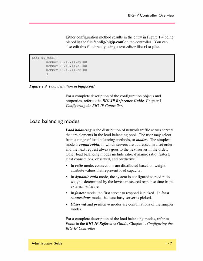
Either configuration method results in the entry in Figure 1.4 being placed in the file /config/bigip.conf on the controller. You can also edit this file directly using a text editor like vi or pico.
For a complete description of the configuration objects and properties, refer to the BIG-IP Reference Guide, Chapter 1, Configuring the BIG-IP Controller.
Load balancing modes
Load balancing is the distribution of network traffic across servers that are elements in the load balancing pool. The user may select from a range of load balancing methods, or modes. The simplest mode is round robin, in which servers are addressed in a set order and the next request always goes to the next server in the order. Other load balancing modes include ratio, dynamic ratio, fastest, least connections, observed, and predictive.
• In ratio mode, connections are distributed based on weight attribute values that represent load capacity.
• In dynamic ratio mode, the system is configured to read ratio weights determined by the lowest measured response time from external software.
• In fastest mode, the first server to respond is picked. In least connections mode, the least busy server is picked.
• Observed and predictive modes are combinations of the simpler modes.
For a complete description of the load balancing modes, refer to Pools in the BIG-IP Reference Guide, Chapter 1, Configuring the BIG-IP Controller.
pool my_pool { member 11.12.11.20:80 member 11.12.11.21:80 member 11.12.11.22:80 }
Figure 1.4 Pool definition in bigip.conf
Administrator Guide 1 - 7
Chapter 1
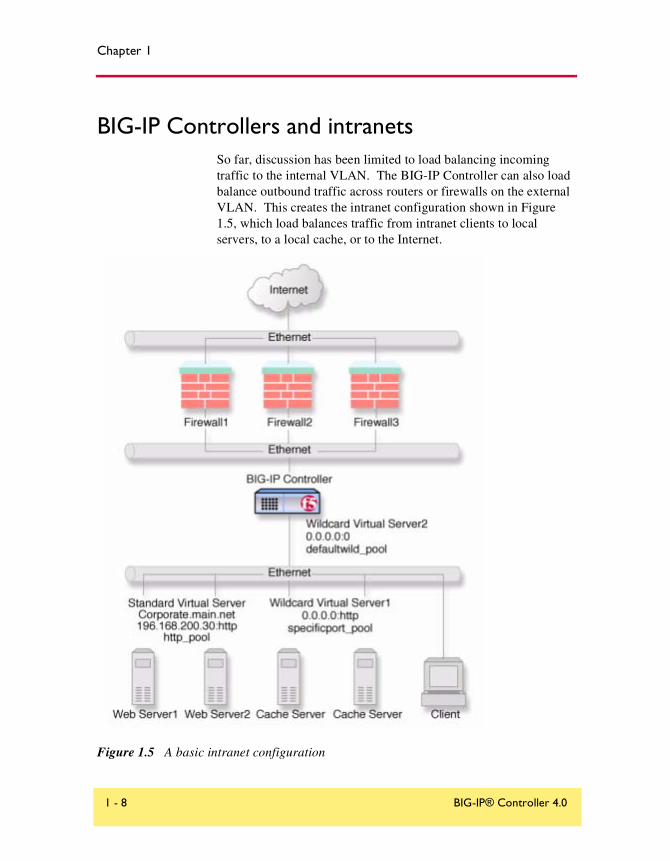
BIG-IP Controllers and intranetsSo far, discussion has been limited to load balancing incoming traffic to the internal VLAN. The BIG-IP Controller can also load balance outbound traffic across routers or firewalls on the external VLAN. This creates the intranet configuration shown in Figure 1.5, which load balances traffic from intranet clients to local servers, to a local cache, or to the Internet.
Figure 1.5 A basic intranet configuration
1 - 8 BIG-IP® Controller 4.0

BIG-IP Controller Overview
This solution utilizes two wildcard virtual servers: Wildcard Virtual Server1, which is HTTP port specific, and Wildcard Virtual Server2, which is not port specific. This way, all non-HTTP requests to addresses not on the intranet are directed to the cache server, which will provide the resources if cached, and otherwise will access them directly from the Internet. All non-HTTP requests not on the intranet will be directed to the Internet.
For detailed information on this solution, refer to Chapter 4, A Simple Intranet Configuration.
Bidirectional load balancing
The intranet configuration shown in Figure 1.5 would typically be a part of larger configuration supporting inbound and outbound traffic.
Administrator Guide 1 - 9

Chapter 1
Figure 1.6 shows traffic being load balanced bidirectionally across three firewalls.
Figure 1.6 Load balancing firewalls
1 - 10 BIG-IP® Controller 4.0

BIG-IP Controller Overview
This configuration requires two BIG-IP Controllers (or controller redundant pairs), and the creation of three load balancing pools with corresponding virtual servers. A virtual server on the inside BIG-IP Controller (BIG-IP Controller1 in Figure 1.6) load balances incoming requests across the enterprise servers. A virtual server on the outside BIG-IP Controller (BIG-IP Controller2 in Figure 1.6) load balances incoming requests across the external interfaces of the firewalls. A third virtual server on the inside BIG-IP Controller redundant system load balances outbound requests across the internal interfaces of the firewalls.
For detailed information on this solution, refer to Chapter 9, Balancing Two-Way Traffic Across Firewalls.
Cache controlUsing cache control features, you can create rules to distribute content among three server pools, an origin server pool, a cache pool for cachable content, and a hot pool. The origin pool members contain all content. The cache pool members contain content that is considered cachable (for example all HTTP and all GIF content). The hot pool members contain cachable content that is considered hot, that is, frequently accessed, as determined by a threshold you set. Once identified, hot content is distributed and load balanced across the pool to maximize processing power when it is hot, and localized to the hot pool when it is cool (less frequently accessed).
A special cache feature is destination address affinity (also called sticky persistence). This feature directs requests for a certain destination to the same proxy server, regardless of which client the request comes from. This saves the other proxies from having to duplicate the web page in their caches, wasting memory.
For detailed information about cache rules, refer to Rules in the BIG-IP Reference Guide, Chapter 1, Configuring the BIG-IP Controller.
Administrator Guide 1 - 11
Chapter 1
SSL accelerationSSL acceleration uses special software with an accelerator card to speed the encryption and decryption of encoded content. This greatly speeds the flow of HTTPS traffic without affecting the flow of non-HTTPS traffic. In addition, using add-on BIG-IP e-Commerce Controllers, it is possible to create a scalable configuration that can grow with your network.
For detailed information about SSL acceleration, refer to Chapter 8, Configuring an SSL Accelerator.
Content conversionContent conversion is the on-the-fly switching of URLs to ARLs (Akamai Resource Locators) for web resources that are stored geographically nearby on the Akamai Freeflow NetworkTM. This greatly speeds download of large, slow-to-load graphics and other types of objects.
For detailed information about content conversion, refer to Chapter 13, Configuring a Content Converter.
VLANsThe internal and external VLANs created on the BIG-IP Controller are by default the separate port-specified VLANs external and internal, with the BIG-IP Controller functioning as an L2 switch. In conformance with IEE802.lq, the BIG-IP Controller supports both port-specified VLAN and tagged VLANs. This adds the efficiency and flexibility of VLAN segmentation to traffic handling between the networks. For example, with VLANs it is no longer necessary to change any IP addresses after inserting a BIG-IP Controller into a single network.
1 - 12 BIG-IP® Controller 4.0

BIG-IP Controller Overview
VLAN capability also supports multi-site hosting and allows the BIG-IP Controller to fit into and extend a pre-existing VLAN segmentation, or to serve as a VLAN switch in creating a VLAN segmentation for the wider network.
For detailed information on VLANs, refer to VLANs in the BIG-IP Reference Guide, Chapter 1, Configuring the BIG-IP Controller.
Link aggregation and link failover
Links (individual physical interfaces) on the BIG-IP Controller may be aggregated by software means to form a trunk (an aggregation of links). This link aggregation increases the bandwidth of the individual links in an additive manner. Thus four fast Ethernet links, if aggregated, create a single 400 Mb/s link. Link aggregation is highly useful with asymmetric loads. Another advantage of link aggregation is link failover. If one link in an trunk goes down, traffic is simply redistributed over the remaining links. Link aggregation conforms to IEEE 802.3ad.
Configuring redundant BIG-IP Controller pairsBIG-IP Controllers may be configured in redundant pairs, with one unit active and the other in standby mode. This is made convenient by the fact that once one unit has been configured, this configuration can be copied automatically to the other unit, a process called synchronization. Once the systems have been synchronized, a failure detection system determines whether the active unit is in failure mode and automatically re-directs traffic to standby unit. This process is called failover.
A special feature of redundant pairs is optional state mirroring. When you use the mirroring feature, the standby controller maintains the same state information as the active controller. Transactions such as FTP file transfers continue as though uninterrupted if the standby controller becomes active.
Administrator Guide 1 - 13

Chapter 1
For detailed information about configuring redundant pairs, refer to Redundant Systems in the BIG-IP Reference Guide, Chapter 1, Configuring the BIG-IP Controller.
Making hidden nodes accessibleTo perform load balancing, the BIG-IP Controller hides physical servers behind a virtual server. This prevents them from receiving direct administrative connections or from initiating requests as clients (for example, to download software upgrades.) There are two basic methods for making nodes on the internal VLAN routable to the outside world: forwarding and address translation.
Forwarding
Forwarding is the simple exposure of a node’s IP address to the BIG-IP Controller’s external VLAN so that clients can use it as a standard routable address. There are two types of forwarding, IP forwarding and the forwarding virtual server. IP forwarding exposes all nodes and all ports on the internal VLAN. You can use the IP filter feature to implement a layer of security.
A forwarding virtual server is like IP forwarding but exposes only selected servers and/or ports.
Address translation
Address translation consists of providing a routable alias that a node can use as its source address when acting as a client. There are two types of address translation: NAT (Network Address Translation) and SNAT (Secure Network Address Translation). NATs are assigned one per node and can be used for both outbound and inbound connections. SNATs may be assigned to multiple nodes and permit only outbound connections, hence the greater security.
1 - 14 BIG-IP® Controller 4.0

BIG-IP Controller Overview
For detailed information about address translation, refer to the sections NATs, SNATs, and IP Forwarding in the BIG-IP Reference Guide, Chapter 1, Configuring the BIG-IP Controller.
Monitoring and administrationThe BIG-IP Controller provides two types of monitoring, health monitoring and statistical monitoring.
Health monitors
Health monitoring is the automatic periodic checking of all nodes in load balancing pools to determine if the node is fully functional. A node that fails its health check is marked down and traffic is no longer directed to it. The controller offers ECV (Extended Content Verification) and EAV (Extended Application Verification) monitors covering all the standard protocols. All monitors are user-configurable and a special external monitor is included for user-supplied pingers.
For detailed information about health monitors, refer to the BIG-IP Reference Guide, Chapter 1, Configuring the BIG-IP Controller.
Statistical monitoring
The BIG-IP Controller provides multiple windows into its operation, including the Configuration utility, bigpipe, and utilities for logging and the display of statistics on specific objects. For example, one utility, Big/stat, allows you monitor statistics specific to virtual servers and nodes, such as the number of current connections or the number of packets processed since the last reboot. In addition, the BIG-IP Controller has simple network management protocol (SNMP) and management information bases (MIBs) to allow you to configure traps or poll the controller with your standard network management station (NMS).
Administrator Guide 1 - 15

Chapter 1
For detailed information on monitoring and administration features and utilities, refer to Chapter 18, Monitoring and Administration.
1 - 16 BIG-IP® Controller 4.0

2
Basic Web Site and E-Commerce Configuration
• Working with a basic web site and e-commerce configuration
• Configuring a basic e-commerce site
• Additional configuration options
Basic Web Site and E-Commerce Configuration
Working with a basic web site and e-commerce configuration
The most common application of the BIG-IP Controller is distributing traffic across an array of web servers that host standard web traffic, including e-commerce traffic. Figure 2.1 shows a configuration where a BIG-IP Controller load balances two sites: www.MySite.com and store.MySite.com. The www.MySite.com site provides standard web content, and the store.MySite.com site is the e-commerce site that sells items to www.MySite.com customers.
To set up load balancing for these sites, you need to create two pools that are referenced by two virtual servers, one for each site. Even though the sites are related and they may even share the same IP address, each requires its own virtual server because it uses a different port to support its particular protocol: port 80 for the HTTP traffic going to www.MySite.com, and port 443 for the SSL traffic going to store.MySite.com. Note that this is true even when there are a port 80 and a port 443 on the same physical server, as in the case of Server 2.
Note
Note that in this example, as in all examples in this guide, we use only non-routable IP addresses. In a real topology, the virtual server IP addresses would have to be routable on the Internet.
Administrator Guide 2 - 1

Chapter 2
Figure 2.1 A basic configuration
Configuring a basic e-commerce siteTo configure the e-commerce site, you need to complete the following tasks in order:
• Define the load balancing pools
• Define virtual servers for the inbound traffic
Defining the pools
The first step in a basic configuration is to define the two load balancing pools, one for HTTP, the other for SSL.
2 - 2 BIG-IP® Controller 4.0

Basic Web Site and E-Commerce Configuration
To create pools using the Configuration utility
1. In the navigation pane, click Pools.The Pools screen opens.
2. Click the Add button.The Add Pool screen opens.
3. In the Add Pool screen, configure the attributes you want to use with the pool. For additional information about configuring a pool, click the Help button.
Configuration Notes
• For this example, you would create an HTTP pool named http_pool and an SSL pool named ssl_pool.
• http_pool contains the following members:192.168.100.1:80192.168.100.2:80
• ssl_pool contains the following members:192.168.100.2:443192.168.100.3:443
To define the pools from the command line
To define a pool from the command line, use the following syntax:b pool <pool_name> {member <member_definition> ... member
<member_definition>}
To create the pools http_pool and ssl_pool from the command line, you would type the following commands:
b pool http_pool { member 192.168.100.1:80 member 192.168.100.2:80 }
b pool ssl_pool { member 192.168.100.2:443 member 192.168.100.3:443 }
Administrator Guide 2 - 3
Chapter 2
Defining the virtual servers
The next step in a basic configuration is to define the virtual servers that reference http_pool and ssl_pool, respectively.
To define the virtual servers using the Configuration utility
1. In the navigation pane, click Virtual Servers.The Virtual Servers screen opens.
2. Click the Add button.The Add Virtual Server screen opens.
3. In the Add Virtual Server screen, configure the attributes that you want to use with the virtual server. For additional information about configuring a virtual server, click the Help button.
Configuration note
• For this example, create a virtual server 192.168.200.10:80 that uses http_pool and a virtual server 192.168.200.10:443 that uses ssl_pool
To define the virtual servers from the command line
Use the bigpipe virtual command as shown below. You can use standard service names in place of port numbers. If you have DNS configured, you can also use host names in place of IP addresses.b virtual <virt IP>:<port> use pool <pool_name>
The following command defines a virtual server that maps to pools http_pool and ssl_pool, respectively:b virtual 192.168.200.10:80 use pool http_pool
b virtual 192.168.200.10:443 use pool ssl_pool
2 - 4 BIG-IP® Controller 4.0

Basic Web Site and E-Commerce Configuration
Additional configuration optionsWhenever a BIG-IP Controller is configured, a number of options are available to the user:
◆ You have the option in all configurations to configure a redundant BIG-IP Controller for fail-over. Refer to Redundant Systems in the BIG-IP Reference Guide, Chapter 1, Configuring the BIG-IP Controller.
◆ All configurations have health monitoring options. Refer to Health Monitors in the BIG-IP Reference Guide, Chapter 1, Configuring the BIG-IP Controller.
◆ When you create a pool, there is an option to set up persistence and a choice of load balancing methods. Refer to Pools in the BIG-IP Reference Guide, Chapter 1, Configuring the BIG-IP Controller.
Administrator Guide 2 - 5

3
Installing a BIG-IP Controller without Changing the IP Network
• Installing a BIG-IP Controller without changing IP networks
• Additional configuration options

Installing a BIG-IP Controller without Changing the IP Network
Installing a BIG-IP Controller without changing IP networks
A combination of several features of the BIG-IP Controller allow you to place a controller in a network without changing the existing IP network.
The following figure shows the data center topology before you add the BIG-IP Controller. The data center has one LAN, with one IP network, 10.0.0.0. The data center has one router to the Internet, two web servers, and a back-end database server.
Figure 3.1 Existing data center network structure
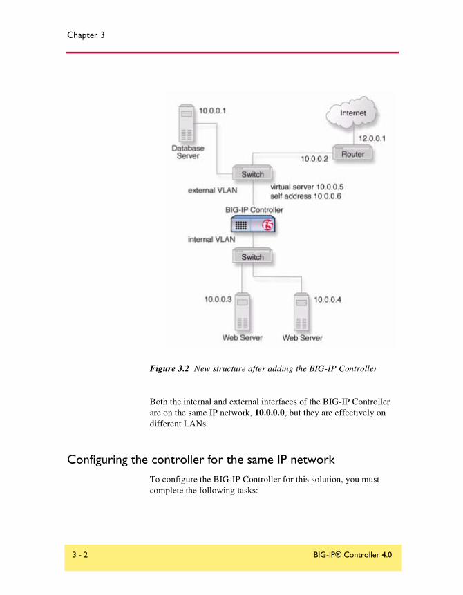
The existing data center structure does not support load balancing or high availability. Figure 3.2 is an example of the data center topology after you add the BIG-IP Controller.
Administrator Guide 3 - 1
Chapter 3
Figure 3.2 New structure after adding the BIG-IP Controller
Both the internal and external interfaces of the BIG-IP Controller are on the same IP network, 10.0.0.0, but they are effectively on different LANs.
Configuring the controller for the same IP networkTo configure the BIG-IP Controller for this solution, you must complete the following tasks:
3 - 2 BIG-IP® Controller 4.0

Installing a BIG-IP Controller without Changing the IP Network
◆ Remove the self IP addresses from the individual VLANsRemove the self IP addresses from the individual VLANs. Routing is handled by the self IP address you create for the VLAN group.
◆ Create a VLAN groupCreate a VLAN group that includes the internal and external VLANs. This enables L2 forwarding.
◆ Create a self IP for the VLAN groupThe self IP for the VLAN group provides a route for packets destined for the network.
◆ Create a pool of web serversCreate a pool that contains the web servers that you want to load balance.
◆ Create a virtual serverCreate a virtual server that load balances the web servers.
Note
This example assumes that are using the default internal and external VLAN configuration with self IP addresses on each VLAN that are on the same IP network on which you are installing the controller.
Note
The default route on each content server should be set to the IP address of the router. In this example, you set the default route to 10.0.0.2
Administrator Guide 3 - 3

Chapter 3
Removing the self IP addresses from the individual VLANs
Remove the self IP addresses from the individual VLANs. After you create the VLAN group, you will create another self IP address for the VLAN group for routing purposes. The individual VLANs no longer need their own self IP addresses.
WARNING
We recommend that you perform this step from the console. If you are connected from a remote workstation, you will be disconnected when you delete the self IP addresses.
To remove the self IP addresses from the default VLANs using the Configuration utility
1. In the navigation pane, click Network.The VLANs screen opens.
2. In the VLANs screen, click the Self IP Addresses tab.The Self IP Addresses screen opens.
3. Delete the self IP addresses for the external and internal VLANs
To delete self IP addresses from the individual VLANs from the command line
To delete the self IP addresses from the individual VLANs, use the following syntax.b self <ip addr> delete
Repeat the command to delete each self IP address on the internal and external VLANs.
3 - 4 BIG-IP® Controller 4.0
Installing a BIG-IP Controller without Changing the IP Network
Creating a VLAN group
Create a VLAN group that includes the internal and external VLANs. Packets received by a VLAN in the VLAN group are copied onto the other VLAN in the group. This allows traffic to pass through the BIG-IP Controller on the same IP network.
Tip
A VLAN group name can be used anywhere a VLAN name can be used.
To create a VLAN group from the Configuration utility
1. In the navigation pane, click Network.The VLANs screen opens.
2. In the VLANs screen, click the VLAN Groups tab.The VLAN Groups screen opens.
3. In the VLAN Groups screen, click the Add button to add the VLAN group.
Configuration notes
• For this example, the VLAN group name is myvlangroup.
• Make sure the Proxy Forward check box is checked.
• Add the internal and external VLANs to the VLAN group.
To create a VLAN group from the command line
To create the VLAN group myvlangroup from the command line, type the following command:b vlangroup myvlangroup { vlans add internal external }
Creating a self IP for the VLAN group
The self IP for the VLAN group provides a route for packets destined for the network. With the BIG-IP Controller, the path to an IP network is a VLAN. However, with the VLAN group feature
Administrator Guide 3 - 5

Chapter 3
used in this example, the path to the IP network 10.0.0.0 is actually through more than one VLAN. Since IP routers are designed to have only one physical route to a network, a routing conflict can occur. The self IP address feature on the BIG-IP Controller allows you to resolve the routing conflict by putting a self IP address on the VLAN group.
To create a self IP address for a VLAN group using the Configuration utility
1. In the navigation pane, click Network.The VLANs screen opens.
2. In the VLANs screen, click the Self IP Addresses tab.The Self IP Addresses screen opens.
3. In the Self IP Addresses screen, click the Add button to start the Add Self IP Address wizard.
Configuration notes
• For this example, the self IP address you add for the VLAN group is 10.0.0.6.
• When you choose the VLAN you want to apply the self IP address to, select the VLAN group you created that contains the internal and external VLANs.
To create a self IP address for a VLAN group from the command line
To create a self IP address on the VLAN group, type the following command:b self 10.0.0.6 vlan myvlangroup netmask 255.255.255.0
Creating the pool of web servers to load balance
After you create the network environment for the BIG-IP Controller, you can create the pool of web servers you want to load balance.
3 - 6 BIG-IP® Controller 4.0
Installing a BIG-IP Controller without Changing the IP Network
To create a pool using the Configuration utility
1. In the navigation pane, click Pools.The Pools screen opens.
2. In the Pools screen, click the Add button to start the Add Pool wizard.
Configuration note
• For this example, the pool contains the web servers 10.0.0.3 and 10.0.0.4.
To create a pool from the command line
To create a pool from the command line, type the following command:b pool mywebpool { member 10.0.0.3 member 10.0.0.4 }
In this example, you create the pool name mywebpool with the members 10.0.0.3 and 10.0.0.4.
Creating the virtual server to load balance the web servers
After you create the pool of web servers you want to load balance, you can create the virtual server.
To create a virtual server using the Configuration utility
1. In the navigation pane, click Virtual Servers.The Virtual Servers screen opens.
2. In the Virtual Servers screen, click the Add button to start the Add Virtual Server wizard.
Configuration notes
• For this example, the virtual server address is 10.0.0.5.
• Add the pool that contains the web servers 10.0.0.3 and 10.0.0.4.
Administrator Guide 3 - 7

Chapter 3
To create a virtual server from the command line
To create the virtual server for this example from the command line, type the following command:b virtual 10.0.0.5:80 use pool mywebpool
In this example, mywebpool contains the web servers.
Additional configuration optionsWhenever a BIG-IP Controller is configured, a number of options are available to the user:
◆ You have the option in all configurations to configure a redundant BIG-IP Controller for fail-over. Refer to Redundant Systems in the BIG-IP Reference Guide, Chapter 1, Configuring the BIG-IP Controller.
◆ All configurations have health monitoring options. Refer to Health Monitors in the BIG-IP Reference Guide, Chapter 1, Configuring the BIG-IP Controller.
When you create a pool, there is an option to set up persistence and a choice of load balancing methods. Refer to Pools in the BIG-IP Reference Guide, Chapter 1, Configuring the BIG-IP Controller.
3 - 8 BIG-IP® Controller 4.0

4
A Simple Intranet Configuration
• Working with a simple intranet configuration
• Additional configuration options

A Simple Intranet Configuration
Working with a simple intranet configurationThe simple intranet solution described in this chapter is commonly found in a corporate intranet (Figure 4.1). In this scenario, the BIG-IP Controller performs load balancing for several different types of connection requests:
◆ HTTP connections to the company’s intranet web site. The BIG-IP Controller load balances the two web servers that host corporate intranet web site, Corporate.main.net.
◆ HTTP connections to Internet content. These are handled though a pair of cache servers, also load balanced by the BIG-IP Controller.
◆ Non-HTTP connections the Internet.
Administrator Guide 4 - 1

Chapter 4
Figure 4.1 A simple intranet configuration
As Figure 4.1 shows, the non-intranet connections are handled by wildcard virtual servers, that is, servers with the IP address 0.0.0.0 (or * or "any"). The wildcard virtual server handling traffic to the cache servers is port specific, specifying port 80 for HTTP requests. This way all HTTP requests not matching an IP address on the intranet are directed to the cache server. The wildcard virtual server handling non-HTTP requests is a default wildcard server. A default wildcard virtual server is one that uses only port
4 - 2 BIG-IP® Controller 4.0

A Simple Intranet Configuration
0 (or any or * or "" [blank string]). This makes it a catch-all match for outgoing traffic that does not match any standard virtual server or any port-specific wildcard virtual server.
Creating the simple intranet configuration
To create this configuration, you need to complete the following tasks in order:
• Create load balancing poolsCreate pools for the intranet servers you want to load balance and one for the cache server.
• Create virtual serversCreate the virtual servers for each pool and for the non-HTTP requests.
Defining the poolsDefine the two load balancing pools, one for the internal servers, the other for the cache servers.
To create pools using the Configuration utility
1. In the navigation pane, click Pools.The Pools screen opens.
2. Click the Add button.The Add Pool screen opens.
3. In the Add Pool screen, configure the pool attributes. For additional information about configuring a pool, click the Help button.
Configuration notes
• For this example, you would create two pools: http_pool and specificport_pool.
Administrator Guide 4 - 3

Chapter 4
• http_pool has members 192.168.100.10:80 and 192.168.100.11:80.
• specificport_pool has members 192.168.100.20:80 and 192.168.100.21:80.
To create the pools from the command line
To define a pool from the command line, use the following syntax:b pool <pool_name> { member <member_definition> ... member
<member_definition>}
To create the pools http_pool and specificport_pool from the command line, you type the following commands:
b pool http_pool { member 192.168.100.10:80 member 192.168.100.11:80 }
b pool specificport_pool { member 192.168.100.20:80 member 192.168.100.20:80}
Defining the virtual servers
The next step in a basic configuration is to define the virtual servers that reference http_pool and specificport_pool, respectively, and a default forwarding virtual server.
To define the virtual servers using the Configuration utility
1. In the navigation pane, click Virtual Servers.The Virtual Servers screen opens.
2. Click the Add button.The Add Virtual Server screen opens.
3. In the Add Virtual Server screen, configure the virtual server attributes. For additional information about configuring a virtual server, click the Help button.
Configuration notes
For this example, create three virtual servers:
• 192.168.200.30:80 using http_pool
4 - 4 BIG-IP® Controller 4.0

A Simple Intranet Configuration
• 0.0.0.0:80 using specificport_pool
• 0.0.0.0:0 as forwarding server (no pool)
To define the virtual servers from the command line
To define a virtual server from the command line, use the following syntax:b virtual <virt IP>:<port> use pool <pool_name>
You can use standard service names in place of port numbers. If you have DNS configured, you can also use host names in place of IP addresses.
The following commands define virtual servers that map to the pools http_pool and specificport_pool, respectively, and a forwarding virtual server:b virtual 192.168.200.30:80 use pool http_pool
b virtual 0.0.0.0:80 use pool specificport_pool
b virtual 0.0.0.0:0 forward
Additional configuration optionsWhenever you configure a BIG-IP Controller, a number of options are available to you:
◆ You have the option in all configurations to configure a redundant BIG-IP Controller for fail-over. Refer to Redundant Systems in the BIG-IP Reference Guide, Chapter 1, Configuring the BIG-IP Controller.
◆ All configurations have health monitoring options. Refer to Health Monitors in the BIG-IP Reference Guide, Chapter 1, Configuring the BIG-IP Controller.
◆ When you create a pool, there is an option to set up persistence and a choice of load balancing methods. Refer to Pools in the BIG-IP Reference Guide, Chapter 1, Configuring the BIG-IP Controller.
Administrator Guide 4 - 5
5
Load Balancing ISPs
• Using ISP load balancing
• Configuring network address translation on routers
• Enabling service 80 and service 443
• Additional configuration options

Load Balancing ISPs
Using ISP load balancingYou may find that as your network grows, or network traffic increases, you need to add an additional connection to the internet. You can use this configuration to add an additional Internet connection to your existing network. Figure 5.1 shows a network configured with two Internet connections.
Figure 5.1 An example of an additional internet connection
This type of configuration requires you to configure network address translation (NAT) on your routers. If your routers cannot perform NAT, you can use the VLAN SNAT automap feature on the BIG-IP Controller.
Administrator Guide 5 - 1

Chapter 5
Configuring ISP load balancing
First, you must complete a series of tasks on the BIG-IP Controller in this order:
• Create two load balancing poolsDefine one pool that load balances the content servers. The other pool balances the inside addresses of the routers.
• Configure virtual serversConfigure virtual servers to load balance inbound connections across the servers and one to load balance outbound connections across the routers.
• Configure NATs or a SNAT automapConfigure NATs or SNAT automap for outbound traffic so that replies will arrive though the same ISP the request went out on.
• Enable service 80 and service 443Enable service 80 and service 443 on the controller. This step is only required if you configure this solution from the command line. The web-based Configuration utility automatically opens the ports.
Defining the pools for an additional Internet connection
First, define one pool that load balances the content servers and one pool for load balancing the routers.
To create pools using the Configuration utility
1. In the navigation pane, click Pools.The Pools screen opens.
2. Click the Add button.The Add Pool screen opens.
3. In the Add Pool screen, configure the pool attributes. For additional information about this screen, click the Help button.
Configuration notesFor this example, create two pools, server_pool and router_insides.
5 - 2 BIG-IP® Controller 4.0
Load Balancing ISPs
• server_pool contains the members <server1> and <server2>
• router_insides contains the router inside addresses <router1> and <router2>
To create pools from the command line
Use the following command to define the pool server_pool for the nodes that handle the requests to virtual server 205.100.19.22:80:
b pool server_pool { member <server1>:80 member <server2>:80 member <server3>:80 }
Replace <server1>, <server2>, and <server3> with the IP address of the respective server.
Use the following command to create the pool router_insides:b pool router_insides { member <router1>:0 member <router2>:0 }
Replace <router1> and <router2> with the internal IP address of the respective routers.
Defining the virtual servers for an additional Internet connection
After you create the pools, you can configure the virtual servers. Configure a virtual server to load balance inbound connections across the servers, and a virtual server to load balance outbound connections across the routers.
To define the virtual servers using the Configuration utility
1. In the navigation pane, click Virtual Servers.The Virtual Servers Screen opens.
2. Click the Add button.The Add Virtual Server screen opens.
3. Fill in the attributes for the virtual server. For additional information about this screen, click the Help button.
Administrator Guide 5 - 3

Chapter 5
Configuration note
• For the inbound connections, create the virtual server 205.100.19.22:80 and use pool server_pool.
• For the outbound connections, create a wildcard virtual server 0.0.0.0:0 and use pool router_insides.
To define the virtual servers from the command line
To handle inbound traffic, create the virtual server for the pool server_pool with the following command:b virtual 205.100.92.22:80 use pool server_pool
To handle outbound traffic, create a wildcard virtual server for the pool router_insides with the following command:bipipe virtual 0.0.0.0:0 use pool router_insides
Configuring network address translation on routers
You must now set up address translation for outbound traffic so that replies will arrive though the same ISP that the request went out on. Specifically, you must either configure your routers so that they perform network address translation (NAT), or you must configure SNAT automap.
For instructions on NAT configuration, refer to your router documentation.
To set up a SNAT automap, perform the following tasks:
• Assign IP-specific self addresses to the BIG-IP Controller external VLAN, corresponding to the IP networks of the two routers.
• Enable SNAT automap for each of the self addresses.
• Enable SNAT automap for the internal VLAN.
5 - 4 BIG-IP® Controller 4.0

Load Balancing ISPs
To create self addresses and enable SNAT automap using the Configuration utility
1. In the navigation pane, click Network.The Network tabs appear.
2. Click the Self IP Addresses tab.The Self IP Addresses screen opens.
3. Click the Add button.The Add Self IP Address screen opens.
4. In the Add Self IP Address screen, for each router, add a new self IP address that matches the network of the router, with the inside IP network address of the router and SNAT Automap enabled.
5. On the Network screen, click the VLANs tab.The VLANs screen opens.
6. On the VLANs screen, click the internal VLAN.The VLAN Internal screen opens.
7. In the VLAN Internal screen, enable SNAT Automap.For additional information about configuring a VLAN, click the Help button.
To create self addresses and enable SNAT automap from the command line
Create IP-specific self addresses on the external VLAN:b self <ip_addr1> vlan <ext_vlan> snat automap enable
b self <ip_addr2> vlan <ext_vlan> snat automap enable
Enable snat automap on the internal VLAN:b vlan <int_vlan> snat automap enable
For this example you might create the following addresses:b self 11.11.11.5 vlan external snat automap enable
b self 11.11.12.5 vlan external snat automap enable
b vlan internal snat automap enable
Administrator Guide 5 - 5
Chapter 5
Enabling service 80 and service 443This step is only required if you configure this solution from the command line. If you use the web-based Configuration utility for this solution, the services are automatically enabled. Use the following command to enable service 80 and service 443.b service 80 443 tcp enable
Additional configuration optionsWhenever a BIG-IP Controller is configured, you have a number of options available to you:
◆ You have the option in all configurations to configure a redundant BIG-IP Controller for fail-over. Refer to Redundant Systems in the BIG-IP Reference Guide, Chapter 1, Configuring the BIG-IP Controller.
◆ All configurations have health monitoring options. Refer to Health Monitors in the BIG-IP Reference Guide, Chapter 1, Configuring the BIG-IP Controller.
◆ When you create a pool, there is an option to set up persistence and a choice of load balancing methods. Refer to Pools in the BIG-IP Reference Guide, Chapter 1, Configuring the BIG-IP Controller.
5 - 6 BIG-IP® Controller 4.0

6
Load Balancing VPNs
• Working with VPN load balancing
• Using VPN and router load balancing
• Additional configuration options

Load Balancing VPNs
Working with VPN load balancingYou can use the BIG-IP Controller to load balance virtual private network (VPN) gateways used to connect two private networks. Figure 6.1 shows a configuration of this type.
Figure 6.1 An example of a VPN load balancing configuration
Administrator Guide 6 - 1
Chapter 6
Configuring VPN load balancing
The following tasks show only how to configure the BIG-IP Controller on network 192.168.13.100 (BIG-IP 2). The configuration for BIG-IP 1 on 192.168.11.100 is the same, only with different network numbers.
◆ Create two load balancing poolsOne pool load balances the content servers and the other handles the inside addresses of the three VPNs.
◆ Create three virtual serversOne virtual server references the pool that load balances the content servers. The others handle inbound and outbound traffic for the VPNs.
◆ Enable service 80 and service 443Enable service 80 and 443 for traffic. This step is only required if you configure this solution from the command line. The web-based Configuration utility automatically allows access to the services.
Defining the pools
First, create two pools. Create one pool that load balances the content servers and another pool for load balancing the VPNs.
To create pools using the Configuration utility
1. In the navigation pane, click Pools.The Pools screen opens.
2. Click the Add button.The Add Pool screen opens.
3. In the Add Pool screen, configure the attributes you want to use for the pool. For additional information about this screen, click the Help button.
Configuration notes
• Create a server pool named server_pool. This pool contains the following members: <server1>, <server2>.
6 - 2 BIG-IP® Controller 4.0

Load Balancing VPNs
• Create pool named vpn_insides. This pool contains the following members: <vpn1>, <vpn2>, <vpn3>.
To define pools from the command line
Define the pool server_pool for the content servers.b pool server_pool { member <server1>:80 member <server2>:80 member
<server3>:80 }
Replace <server1>, <server2>, and <server3> with the IP address of the respective server.
Define the pool vpn_insides for the VPNs:b pool vpn_insides { member <vpn1>:* member <vpn2>:* member <vpn3>:* }
Replace <vpn1>, <vpn2>, and <vpn3> with the internal IP address of the respective router. In this example the routers are service checked on port *.
Defining the virtual servers
After you define the pools for the content servers and inside IP addresses of the VPNs, define the following virtual servers for controller BIG-IP 2. You need to define the following three virtual servers.
• A virtual server to load balance the content servers
• A virtual server to forward inbound VPN traffic
• A virtual server to load balance outbound traffic across the VPNs
To define the virtual server using the Configuration utility
1. In the navigation pane, click Virtual Servers.
2. Click the Add button.The Add Virtual Server screen opens.
3. Fill in the attributes for the virtual server. For additional information about this screen, click the Help button.
Administrator Guide 6 - 3
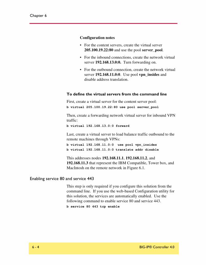
Chapter 6
Configuration notes
• For the content servers, create the virtual server 205.100.19.22:80 and use the pool server_pool.
• For the inbound connections, create the network virtual server 192.168.13.0:0. Turn forwarding on.
• For the outbound connection, create the network virtual server 192.168.11.0:0. Use pool vpn_insides and disable address translation.
To define the virtual servers from the command line
First, create a virtual server for the content server pool:b virtual 205.100.19.22:80 use pool server_pool
Then, create a forwarding network virtual server for inbound VPN traffic:b virtual 192.168.13.0:0 forward
Last, create a virtual server to load balance traffic outbound to the remote machines through VPNs:b virtual 192.168.11.0:0 use pool vpn_insides
b virtual 192.168.11.0:0 translate addr disable
This addresses nodes 192.168.11.1, 192.168.11.2, and 192.168.11.3 that represent the IBM Compatible, Tower box, and MacIntosh on the remote network in Figure 6.1.
Enabling service 80 and service 443
This step is only required if you configure this solution from the command line. If you use the web-based Configuration utility for this solution, the services are automatically enabled. Use the following command to enable service 80 and service 443.b service 80 443 tcp enable
6 - 4 BIG-IP® Controller 4.0
Load Balancing VPNs
Using VPN and router load balancingYou can use the transparent device load balancing feature in the BIG-IP Controller to connect to private networks, as well as to load balance Internet connections through multiple routers. Figure 6.2 is an example of this network configuration. Note that this configuration uses three interfaces on the BIG-IP Controller. The interface connected to the routers and the interface connected to the servers must be on different VLANs.
Configuring virtual servers for VPN and router load balancing
The following topics deal with only the VPN configuration for the BIG-IP Controller on network 192.168.13.100 is shown (BIG-IP 2). The configuration for 192.168.11.100 is done the same way, but you use different network numbers.
Administrator Guide 6 - 5
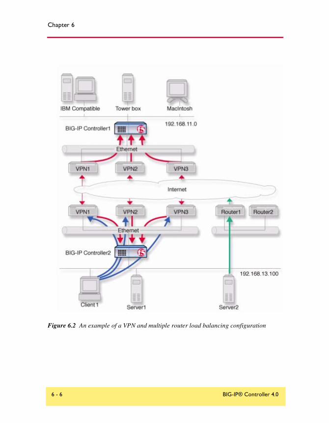
Chapter 6
Figure 6.2 An example of a VPN and multiple router load balancing configuration
6 - 6 BIG-IP® Controller 4.0

Load Balancing VPNs
Configuring VPN and router load balancing
First, complete the following tasks on the BIG-IP Controller:
◆ Create load balancing poolsCreate load balancing pools for the content servers, the routers, and the three VPNs.
◆ Create four virtual serversCreate four virtual servers. The first virtual server load balances inbound Internet traffic. The second virtual server load balances outbound Internet traffic. The third virtual server forwards inbound VPN connections. The fourth virtual server load balances outbound VPN connections.
◆ Configure network address translationConfigure NATs or SNAT automap for outbound traffic so that replies will arrive though the same VPN the request went out on.
◆ Enable service 80 and service 443Enable service 80 and 443 for traffic. This step is only required if you configure this solution from the command line. The web-based Configuration utility automatically opens the ports.
Defining the pools for VPN load balancing
First, create three pools. Create one pool that load balances the content servers, one that load balances the routers, and one that load balances the VPNs.
To create a pool using the Configuration utility
1. In the navigation pane, click Pools.The Pools screen opens.
2. Click the Add button.The Add Pool screen opens.
3. In the Add Pool screen, configure the attributes you want to use for the pool. For additional information about this screen, click the Help button.
Administrator Guide 6 - 7

Chapter 6
Configuration notes
• Create a server pool named server_pool. This pool contains the following members: <server1> and <server2>
• Create a pool named router_insides with the following members: <router1> and <router2>
• Create a pool named vpn_insides. This pool contains the following members: <vpn1>, <vpn2>, and <vpn3>
To define a pool from the command line
First, define the pool server_pool for the content servers:b pool server_pool { member <server1>:80 member <server2>:80 member
<server3>:80 }
You will replace <server1>, <server2>, and <server3> with the IP address of each respective server.
Next, define the pool router_insides for the internal addresses of the routers:
b pool router_insides { member <router1>:0 member <router2>:0 }
Replace <router1> and <router2> with the internal IP address of each respective router.
Finally, define the pool vpn_insides for the internal addresses of the VPN routers:
b pool vpn_insides { member <vpn1>:0 member <vpn2>:0 member <vpn3>:0 }
Replace <vpn1>, <vpn2>, and <vpn3> with the external IP address of each respective router.
Defining the virtual servers for VPN and router load balancing
After you define the pools for the inside IP addresses of the routers, you need to define the following virtual servers for the controller BIG-IP 2.
• A virtual server to load balance the content servers
• A virtual server to load balance the routers
6 - 8 BIG-IP® Controller 4.0

Load Balancing VPNs
• A virtual server to forward inbound connections for the VPNs
• A virtual server to load balance outbound connections for the VPNs
To define the virtual server using the Configuration utility
1. In the navigation pane, click Virtual Servers.The Virtual Servers screen opens.
2. Click the Add button.The Add Virtual Server screen opens.
3. Fill in the attributes for the virtual server. For additional information about this screen, click the Help button.
Configuration notes
• For the inbound Internet connection, configure the virtual server 205.100.92.22:80 using server_pool.
• For the outbound Internet connection, configure the wildcard virtual server 0.0.0.0:0 using router_insides.
• For the inbound VPN connections, create the forwarding network virtual server 192.168.13.0:0. Turn forwarding on.
• For the outbound VPN connections, create the network virtual server 192.168.11.0:0. Use pool vpn_insides and disable port and address translation.
To define virtual servers from the command line
First, configure the controller to handle inbound traffic from the remote network.
Create the virtual server for controller BIG-IP 2 with the following commands:b virtual 192.168.13.0:0 forward
Then, configure BIG-IP 2 to handle outbound traffic. Create a virtual server that sends traffic to the pool you created for the internal interfaces of the VPN routers (vpn_insides). Use the following commands to create virtual servers for connecting to the machines on the remote network:
Administrator Guide 6 - 9

Chapter 6
b virtual 192.168.11.0:0 use pool vpn_insides
b virtual 192.168.11.0:0 translate addr disable
This addresses the nodes 192.168.11.1, 192.168.11.2, and 192.168.11.3 that correspond to the IBM Compatible, Tower box, and MacIntosh on the remote network in Figure 6.2, on page 6-6.
Then, create a virtual server to handle inbound traffic:b virtual 205.100.92.22:80 use pool server_pool
Finally, configure BIG-IP 2 to handle outbound traffic. Create a virtual server that sends traffic to the pool you created for the internal interfaces of the routers (router_insides). Use the following command to create the virtual server:b virtual 0.0.0.0:0 use pool router_insides
Configuring network address translation on routers
For outbound traffic you must now set up address translation so that replies will arrive though the same router the request went out on. Specifically, you must either configure your routers so that they perform network address translation (NAT), or you must configure SNAT automapping.
For instructions on NAT configuration, refer to your router documentation.
To perform the SNAT automap you must perform three steps:
• Assign IP-specific self addresses to the external VLAN corresponding the IP networks of the two routers
• Enable SNAT automap for each of the self addresses.
• Enable SNAT automap for the internal VLAN.
To create self addresses and enable SNAT automap to the router inside interfaces using the Configuration utility
1. In the navigation pane, click Network.The VLANs screen opens.
2. On the VLANs screen, click the Self IP Addresses tab.The Self IP Addresses screen opens.
6 - 10 BIG-IP® Controller 4.0

Load Balancing VPNs
3. Click the Add button.The Add Self IP Address screen opens.
4. In the Add Self IP Address screen, for each router, add a new self IP address with the inside IP network address of the router and SNAT Automap enabled.
5. On the Network screen, click the VLANs tab.The VLANs screen opens.
6. On the VLANS screen, click the internal VLAN.The VLAN Internal screen opens.
7. In the VLAN Internal screen, enable SNAT Automap.For additional information about adding a VLAN, click the Help button.
To create VLAN mappings with SNAT auto mapping to the router inside interfaces from the command line
Create IP-specific self addresses on the third VLAN:b self <ip_addr1> vlan <vlan_name> snat automap enable
b self <ip_addr2> vlan vlan_name> snat automap enable
Enable snat automap on the internal VLAN:b vlan <int_vlan> snat automap enable
For example:b self 11.11.11.5 vlan external snat automap enable
b self 11.11.12.5 vlan external snat automap enabl
b vlan internal snat automap enable
Enabling service 80 and service 443
This step is required only if you configure this solution from the command line. If you use the web-based Configuration utility for this solution, the services are automatically enabled. Use the following command to enable service 80 and service 443.b service 80 443 tcp enable
Administrator Guide 6 - 11

Chapter 6
Additional configuration optionsWhenever a BIG-IP Controller is configured, a number of options are available to the user:
◆ You have the option in all configurations to configure a redundant BIG-IP Controller for fail-over. Refer to Redundant Systems in the BIG-IP Reference Guide, Chapter 1, Configuring the BIG-IP Controller.
◆ All configurations have health monitoring options. Refer to Health Monitors in the BIG-IP Reference Guide, Chapter 1, Configuring the BIG-IP Controller.
◆ When you create a pool, there is an option to set up persistence and a choice of load balancing methods. Refer to Pools in the BIG-IP Reference Guide, Chapter 1, Configuring the BIG-IP Controller.
6 - 12 BIG-IP® Controller 4.0

7
Using IPSEC with VPN Gateways
• Configuring load balancing between VPN gateways
• The VPN sandwich configuration with IPSEC
• Additional configuration options
Using IPSEC with VPN Gateways
Configuring load balancing between VPN gateways
The previous chapter shows how to load balance across three VPN gateways, using a VPN sandwich configuration. The IPSEC protocol (Internet Protocol Security) enables you to load balance between gateways as well. Figure 7.1 shows inbound IPSEC traffic being load balanced to one of three destination VPN gateways.
Administrator Guide 7 - 1

Chapter 7
Figure 7.1 VPN load balancing between VPN gateways
7 - 2 BIG-IP® Controller 4.0
Using IPSEC with VPN Gateways
In this configuration, address translation is on and IPSEC is in tunnel mode with ESP (Encapsulation Security Payload) specified. The hop shown by the blue arrow represents the IPSEC part of the transmission. A packet originating from Client1 with Client6 as its destination is encapsulated by the VPN gateway (VPN5) serving the client and traverses the Internet in this secure form. The BIG-IP Controller then demultiplexes the packet and load balances it to one of three destination gateways: VPN1, VPN2, or VPN3. The VPN to which it is load balanced then becomes the established gateway, or tunnel, for packets from VPN5. Traffic from Client1, a separate VPN connection, would be load balanced to a different destination VPN.
For this configuration to work, IPSEC requires certain special settings on the clients and servers, and on the BIG-IP Controller:
◆ On clients and servers, IPSEC must be configured in tunnel mode with ESP.
◆ You must enable Any IP mode for the virtual servers on the controller.
◆ Enable address translation on the controller.
◆ Enable UDP on the controller to support internet key exchange (IKE) traffic.
◆ Enable persistence across services on the controller.
Configuring IPSEC load balancing
First, configure your servers and clients for IPSEC tunnel mode with ESP. Refer to the documentation provided with the server or client. Be sure to use the same security association for all clients.
Next, complete the following tasks on the BIG-IP Controller:
◆ Create two load balancing poolsCreate two load balancing pools for the VPN destination gateways, one specifying port 500 for internet key exchange, one specifying a wildcard service (0) for Any IP mode.
Administrator Guide 7 - 3

Chapter 7
◆ Create two virtual serversCreate two virtual servers for referencing the two pools, one specifying port 500 for internet key exchange, one specifying a wildcard service (0) for Any IP (IPSEC) traffic.
◆ Enable UDPEnable UDP for internet key exchange (IKE) traffic.
◆ Enable persistenceEnable persistence across services.
Defining the pools
First, define one pool that load balances the VPN destination gateways with a wildcard port, and one pool for load balancing the VPN destination gateways handling service 500 traffic.
To create pools using the Configuration utility
Use this procedure for each BIG-IP Controller that you need to configure.
1. In the navigation pane, click Pools.The Pools screen opens.
2. Click the Add button.The Add Pool screen opens.
3. In the Add Pool screen, configure the attributes you want to use for the pool. For additional information about this screen, click the Help button.
Configuration notes
• Create a VPN pool named vpn_anyip. This pool contains the outside addresses of the three VPN destination gateways with service zero.
• Create a VPN pool named vpn_ike. This pool contains the outside addresses of the three VPN destination gateways with service 500.
7 - 4 BIG-IP® Controller 4.0

Using IPSEC with VPN Gateways
To define pools from the command line
Use the following syntax to define the pools at the command line:b pool <pool_name> { member <member1> member < member2> ...> }
To create the configuration described in this solution, type the following commands:
b pool vpn_anyip { member 10.1.10.1:0 member 10.1.10.2:0 member 10.1.10.3:0 }
b pool vpn_ike { member 10.1.10.1:500 member 10.1.10.2:500 member 10.1.10.3:500 }
Defining the virtual servers
After you define the pools for the VPNs, you can define the following virtual servers on the BIG-IP Controller.
• A virtual server to load balance internet key exchange traffic
• A virtual server to load balance Any IP (IPSEC) traffic
To define the virtual server using the Configuration utility
Use this procedure for each BIG-IP Controller that you need to configure.
1. In the navigation pane, click Virtual Servers.
2. Click the Add button.The Add Virtual Server screen opens.
3. Fill in the attributes for the virtual server. For additional information about this screen, click the Help button.
4. For each of the two VPN load-balancing virtual servers:
a) Click the Virtual Address Properties tab.The Virtual Address Properties screen opens.
b) In the Any IP Traffic field, check the Enable box. Then click Apply.
Configuration notes
• Create the virtual server 192.168.13.100:0 and use the pool vpn_anyip.
Administrator Guide 7 - 5

Chapter 7
• Create the virtual server 192.168.13.100:500 and use the pool vpn_ike.
To define the virtual servers from the command line
Define the virtual servers from the command line as follows:
b virtual 192.168.13.100:0 use pool vpn_anyipb virtual 192.168.13.100:500 use pool vpn_ike
Then, enable Any IP for both virtual servers:
b virtual 192.168.13.100 any_ip enable.
Enabling UDP
After you enable Any IP for the virtual servers, enable UDP 500 so the controller can handle internet key exchange (IKE) traffic:b service 500 udp enable
Enabling persistence across services
Finally, complete the configuration by setting up persistence across services on the BIG-IP Controller:b global persist_across_services enable
The VPN sandwich configuration with IPSECYou can load balance content servers to incoming IPSEC traffic by adding a second BIG-IP Controller in a VPN sandwich configuration. Figure 7.2 shows the VPN sandwich configuration.
7 - 6 BIG-IP® Controller 4.0

Using IPSEC with VPN Gateways
Figure 7.2 VPN load balancing between VPN gateways
Administrator Guide 7 - 7
Chapter 7
When you set up the sandwich configuration, the configuration tasks you use are identical to those you use for the basic VPN IPSEC configuration. The exceptions are that you configure a load balancing pool and virtual server on the second BIG-IP Controller.
Defining the additional pool
To create the pool using the Configuration utility
For the BIG-IP Controller BIG-IP 2:
1. In the navigation pane, click Pools.The Pools screen opens.
2. Click the Add button.The Add Pool screen opens.
3. In the Add Pool screen, configure the attributes you want to use for the pool. For additional information about this screen, click the Help button.
Configuration note
• Create a VPN pool named server_pool. This pool contains as members the addresses of the four content servers, server1, server2, server3, and server4.
To define the pool from the command line
Use the following syntax to define the pools from the command line:
b pool <pool_name> { member <member1> member < member2> ...> }
To create the configuration described in this solution, type the following command.
b pool server_pool { member 10.1.2.1:80 member 10.1.20.2:80 member 10.1.20.3:80 member 10.1.20.4:80 }
7 - 8 BIG-IP® Controller 4.0

Using IPSEC with VPN Gateways
Defining the additional virtual server
To define the additional virtual server using the Configuration utility
For each BIG-IP Controller to be configured:
1. In the navigation pane, click Virtual Servers.The Virtual Servers screen opens.
2. Click the Add button.The Add Virtual Server screen opens.
3. Fill in the attributes for the virtual server. For additional information about this screen, click the Help button.
Configuration note
• Create the virtual server 10.1.20.10:80 and use the pool server_pool.
To define the virtual server from the command line
To define the virtual server from the command line, type the following command.
b virtual 10.1.20.10:80 use pool server_pool
Additional configuration optionsWhenever you configure a BIG-IP Controller, you have a number of options:
◆ You have the option in all configurations to configure a redundant BIG-IP Controller for fail-over. Refer to Redundant Systems in the BIG-IP Reference Guide, Chapter 1, Configuring the BIG-IP Controller.
◆ All configurations have health monitoring options. Refer to Health Monitors in the BIG-IP Reference Guide, Chapter 1, Configuring the BIG-IP Controller.
Administrator Guide 7 - 9

Chapter 7
◆ When you create a pool, there is an option to set up persistence and a choice of load balancing methods. Refer to Pools in the BIG-IP Reference Guide, Chapter 1, Configuring the BIG-IP Controller.
7 - 10 BIG-IP® Controller 4.0

8
Configuring an SSL Accelerator
• Introducing the SSL Accelerator
• Configuring the SSL Accelerator
• Introducing the SSL accelerator scalable configuration
• Additional configuration options

Configuring an SSL Accelerator
Introducing the SSL AcceleratorThe SSL Accelerator feature allows the BIG-IP Controller to accept HTTPS connections (HTTP over SSL), connect to a web server, retrieve the page, and then send the page to the client.
A key component of the SSL Accelerator feature is that the BIG-IP Controller can retrieve the web page using an unencrypted HTTP request to the content server. With the SSL Accelerator feature, you can configure an SSL gateway on the BIG-IP Controller that decrypts HTTP requests that are encrypted with SSL. Decrypting the request offloads SSL processing from the servers to the BIG-IP Controller. This also allows the BIG-IP Controller to use the header of the HTTP request to intelligently control how the request is handled.
When the SSL gateway on the BIG-IP Controller connects to the content server, it uses the original client's IP address and port as its source address and port, so that it appears to be the client (for logging purposes).
This chapter describes the following features of the BIG-IP Controller SSL Accelerator:
• Configuring an SSL Accelerator
• Enabling and disabling an SSL Accelerator
• Viewing the configuration of an SSL Accelerator
• Using an SSL Accelerator scalable configuration
Note
All products except the BIG-IP LoadBalancer, BIG-IP FireGuard Controller, and the BIG-IP Cache Controller support this configuration.
Administrator Guide 8 - 1

Chapter 8
Figure 8.1 An incoming SSL connection received by an SSL Accelerator configured on BIG-IP Controller
Configuring the SSL AcceleratorThere are several steps required to set up the SSL Accelerator on the BIG-IP Controller. These steps include:
• Generating a key and obtaining a certificate
• Configuring the BIG-IP Controller with the certificate and key
• Creating an HTTP virtual server
• Creating the gateway for the SSL Accelerator
8 - 2 BIG-IP® Controller 4.0

Configuring an SSL Accelerator
Generating a key and obtaining a certificate
In order to use the SSL Accelerator feature you must obtain a valid x509 certificate from an authorized certificate authority (CA). The following list contains some companies that are certificate authorities:
• Verisign (http://www.verisign.com)
• Digital Signature Trust Company (http://secure.digsigtrust.com)
• GlobalSign (http://www.globalsign.com)
• GTE Cybertrust (http://www.cybertrust.gte.com)
• Entrust (http://www.entrust.net)
You can generate a key, a temporary certificate, and a certificate request form with the Configuration utility or from the command line.
Note that we recommend using the Configuration utility for this process. The certification process is generally handled through a web page. Parts of the process require you to cut and paste information from a browser window in the Configuration utility to another browser window on the web site of the CA.
Additional information about keys and certificates
You must have a separate certificate for each domain name on each BIG-IP Controller or redundant pair of BIG-IP Controllers, regardless of how many non-SSL web servers are load balanced by the BIG-IP Controller.
If you are already running an SSL server, you can use your existing keys to generate temporary certificates and request files. However, you must obtain new certificates if the ones you have are not for the following web server types:
• Apache + OpenSSL
• Stronghold
Administrator Guide 8 - 3

Chapter 8
Generating a key and obtaining a certificate using the Configuration utility
To obtain a valid certificate, you must have a private key. If you do not have a key, you can use the Configuration utility on the BIG-IP Controller to generate a key and a temporary certificate. You can also use the Configuration utility to create a request file you can submit to a certificate authority (CA). You must complete three tasks in the Configuration utility to create a key and generate a certificate request.
• Generate a certificate request
• Submit the certificate request to a CA and generate a temporary certificate
• Install the SSL certificate from the CA
Each of these tasks is described in detail in the following paragraphs.
To create a new certificate request using the Configuration utility
1. In the navigation pane, click Proxies.The Proxies screen opens.
2. On Proxies screen, click the Create SSL Certificate Request tab.The New SSL Certificate Request screen opens.
3. In the Key Information section, select a key length and key file name.
• Key LengthSelect the key length you want to use for the key. You can choose either 512 or 1024 bytes.
• Keyfile NameType in the name of the key file. This should be the fully qualified domain name of the server for which you want to request a certificate. You must add the .key file extension to the name.
4. In the Certificate Information section, type the information specific to your company. This information includes:
8 - 4 BIG-IP® Controller 4.0

Configuring an SSL Accelerator
• CountryType the two letter ISO code for your country, or select it from the list. For example, the two-letter code for the United States is US.
• State or ProvinceType the full name of your state or province, or select it from the list. You must enter a state or province.
• LocalityType the city or town name.
• OrganizationType the name of your organization.
• Organizational UnitType the division name or organizational unit.
• Domain NameType the name of the domain upon which the server is installed.
• Email AddressType the email address of a person who can be contacted about this certificate.
• Challenge PasswordType the password you want to use as the challenge password for this certificate. The CA uses the challenge password to verify any changes you make to the certificate at a later date.
• Retype PasswordRetype the password you entered for the challenge password.
5. Click the Generate Certificate Request button.After a short pause, the SSL Certificate Request screen opens.
6. Use the SSL Certificate Request screen, to start the process of obtaining a certificate from a CA, and then to generate and install a temporary certificate.
Administrator Guide 8 - 5

Chapter 8
• Begin the process for obtaining a certificate from CAClick on the URL of a CA to begin the process of obtaining a certificate for the server. After you select a CA, follow the directions on their web site to submit the certificate request. After your certificate request is approved, and you receive a certificate back from the CA, see To install certificates from the CA using the Configuration utility, on page 8-9, for information about installing it on the BIG-IP Controller.
• Generate and install a temporary certificateClick the Generate Self-Signed Certificate button to create a self-signed certificate for the server. We recommend that you use the temporary certificate for testing only. You should take your site live only after you receive a properly-signed certificate from a certificate authority. When you click this button, a temporary certificate is created and installed on the BIG-IP Controller. This certificate is valid for 10 years. This temporary certificate allows you to set up an SSL gateway for the SSL Accelerator while you wait for a CA to return a permanent certificate.
Generating a key and obtaining a certificate from the command line
To obtain a valid certificate, you must have a private key. If you do not have a key, you can use the genconf and genkey utilities on the BIG-IP Controller to generate a key and a temporary certificate. The genkey and gencert utilities automatically generate a request file that you can submit to a certificate authority (CA). If you have a key, you can use the gencert utility to generate a temporary certificate and request file.
These utilities are described in the following list:
◆ genconf This utility creates a key configuration file that contains specific information about your organization. The genkey utility uses this information to generate a certificate.
8 - 6 BIG-IP® Controller 4.0

Configuring an SSL Accelerator
◆ genkeyAfter you run the genconf utility, run this utility to generate a temporary 30 day certificate for testing the SSL Accelerator on the BIG-IP Controller. This utility also creates a request file that you can submit to a certificate authority (CA) to obtain a certificate.
◆ gencertIf you already have a key, run this utility to generate a temporary certificate and request file for the SSL Accelerator.
To generate a key configuration file using the genconf utility
If you do not have a key, you can generate a key and certificate with the genconf and genkey utilities. First, run the genconf utility from the root (/) with the following commands:cd /
/usr/local/bin/genconf
The utility prompts you for information about the organization for which you are requesting certification. This information includes:
• The fully qualified domain name (FQDN) of the server
• The two-letter ISO code for your country
• The full name of your state or province
• The city or town name
• The name of your organization
• The division name or organizational unit
For example, Figure 8.2 contains entries for the server my.server.net:
Common Name (full qualified domain name): my.server.netCountry Name (ISO 2 letter code): USState or Province Name (full name): WASHINGTONLocality Name (city, town, etc.): SEATTLEOrganization Name (company): MY COMPANYOrganizational Unit Name (division): WEB UNIT
Figure 8.2 Example entries for the genconf utility
Administrator Guide 8 - 7

Chapter 8
To generate a key using the genkey utility
After you run the genconf utility, you can generate a key with the genkey utility. Type the following command from the root (/) to run the genkey utility:cd /usr/local/bin/genkey <server_name>
For the <service_name>, type the FQDN of the server to which the certificate applies. After the utility starts, it prompts you to verify the information created by the genconf utility. After you run this utility, a certificate request form is created in the following directory:/config/bigconfig/<fqdn>.req
The <fqdn> is the fully qualified domain name of the server. Please contact your CA and follow their instructions for submitting this request form.
In addition to creating a request form that you can submit to a certificate authority, this utility also generates a temporary certificate. The temporary certificate is located in:/config/bigconfig/ssl.crt/<fqdn>.crt
The <fqdn> is the fully qualified domain name of the server.
Note that you must copy the key and certificate to the other controller in a redundant system.
This temporary certificate is good for ten years, but for an SSL proxy you should have a valid certificate from your CA.
WARNING
Be sure to keep your previous key if you are still undergoing certification. The certificate you receive is valid only with the key that originally generated the request.
To generate a certificate with an existing key using the gencert utility
To generate a temporary certificate and request file to submit to the certificate authority with the gencert utility, you must first copy an existing key for a server into the following directory on the BIG-IP Controller:
8 - 8 BIG-IP® Controller 4.0

Configuring an SSL Accelerator
/config/bigconfig/ssl.key/
After you copy the key into this directory, type the following command at the command line:cd /
/user/local/bin/gencert <server_name>
For the <server_name>, type the FQDN of the server to which the certificate applies. After the utility starts, it prompts you for various information. After you run this utility, a certificate request form is created in the following directory:/config/bigconfig/ssl.crt/<fqdn>.req
The <fqdn> is the fully qualified domain name of the server. Please contact your certificate authority (CA) and follow their instructions for submitting this request form.
Installing certificates from the certificate authority (CA)
After you obtain a valid x509 certificate from a certificate authority (CA) for the SSL Accelerator, you must copy it onto each BIG-IP Controller in the redundant configuration. You can configure the accelerator with certificates using the Configuration utility or from the command line.
To install certificates from the CA using the Configuration utility
1. In the navigation pane, click Proxies.The Proxies screen opens.
2. On Proxies screen, click the Install SSL Certificate Request tab.The Install SSL Certificate screen opens.
3. In the Certfile Name box, type the fully qualified domain name of the server with the file extension .crt. If you generated a temporary certificate when you submitted a request to the CA, you can select the name of the certificate from the drop down list. This allows you to overwrite the temporary certificate with the certificate from the CA.
Administrator Guide 8 - 9

Chapter 8
4. Paste the text of the certificate into the Install SSL Certificate window. Make sure you include the BEGIN CERTIFICATE line and the END CERTIFICATE line. For an example of a certificate, see Figure 8.3.
5. Click the Write Certificate File button to install the certificate.
After the certificate is installed, you can continue with the next step in creating an SSL gateway for the server.
To install certificates from the CA using the command line
Copy the certificate into the following directory on each BIG-IP Controller in a redundant system:/config/bigconfig/ssl.crt/
Note
The certificate you receive from the certificate authority (CA) should overwrite the temporary certificate generated by genkey or gencert.
If you used the genkey or gencert utilities to generate the request file, a copy of the corresponding key should already be in the following directory on the BIG-IP Controller:
-----BEGIN CERTIFICATE-----MIIB1DCCAX4CAQAwDQYJKoZIhvcNAQEEBQAwdTELMAkGA1UEBhMCVVMxCzAJBgNVBAgTAldBMRAwDgYDVQQHEwdTZWF0dGxlMRQwEgYDVQQKEwtGNSBOZXR3b3JrczEcMBoGA1UECxMTUHJvZHVjdCBEZXZlbG9wbWVudDETMBEGA1UEAxMKc2VydmVyLm5ldDAeFw0wMDA0MTkxNjMxNTlaFw0wMDA1MTkxNjMxNTlaMHUxCzAJBgNVBAYTAlVTMQswCQYDVQQIEwJXQTEQMA4GA1UEBxMHU2VhdHRsZTEUMBIGA1UEChMLRjUgTmV0d29ya3MxHDAaBgNVBAsTE1Byb2R1Y3QgRGV2ZWxvcG1lbnQxEzARBgNVBAMTCnNlcnZlci5uZXQwXDANBgkqhkiG9w0BAQEFAANLADBIAkEAsfCFXq3Jt+FevxUqBZ9TZ7nHx9uaF5x9V5xMZYgekjc+LrF/yazhmq4PCxrws3gvJmgpTsh50YJrhJgfs2bEgwIDAQABMA0GCSqGSIb3DQEBBAUAA0EAd1q6+u/aMaM2qdo7EjWx14TYQQGomYoqeydlzb/3FOiJAynDXnGnSt+CVvyRXtvmG7V8xJamzkyEpZd4iLacLQ==-----END CERTIFICATE-----
Figure 8.3 An example of a certificate
8 - 10 BIG-IP® Controller 4.0

Configuring an SSL Accelerator
/config/bigconfig/ssl.eky/
WARNING
In a redundant system, the keys and certificates must be in place on both controllers before you configure the SSL Accelerator. You must do this manually; the configuration synchronization utilities do not perform this function.
Creating a pool for the HTTP servers
After you configure the BIG-IP Controller with the certificates and keys, the next step is to create a pool containing the HTTP servers for which the SSL Accelerator handles connections.
To create pools using the Configuration utility:
1. In the navigation pane, click Pools.The Pools screen opens.
2. Click the ADD button.The Add Pool screen opens.
3. In the Add Pool screen, configure the pool attributes. For additional information about configuring a pool, click the Help button.
Configuration note
For this example, you would create an HTTP pool named http_pool that would contain the following members:<server1><server2><server3>
To define the pools from the command line
To define a pool from the command line, use the following syntax:b pool <pool_name> { member <member_definition> ... member
<member_definition>}
To create the pools http_pool and ssl_pool, from the command line, you would type the following commands:
Administrator Guide 8 - 11
Chapter 8
b pool http_pool { member 192.168.100.1:80 member 192.168.100.2:80 }
b pool ssl_pool { member 192.168.100.2:443 member 192.168.100.3:443 }
Creating an HTTP virtual serverThe next task in configuring the SSL Accelerator is to create a virtual server that references the HTTP pool.
To create an HTTP virtual server using the Configuration utility
1. In the navigation pane, click Virtual Severs.The Virtual Servers screen opens.
2. Click the ADD button.The Add Virtual Server screen opens.
3. In the Add Virtual Server screen configure the virtual server.For additional information about configuring a pool, click the Help button.
Configuration note
For this example, you would create a virtual server using the pool http_pool.
To create an HTTP virtual server from the command line
After you have defined a pool that contains the HTTP servers, use the following syntax to create a virtual server that references the pool:b virtual <virt ip>:<port> use pool <pool_name>
For example, if you want to create a virtual server 20.1.1.1:80, that references a pool of HTTP servers named http_pool, you would type the following command:b virtual 20.1.1.1:80 use pool http_pool
After you create the virtual server that references the pool of HTTP servers, you can create an SSL gateway. The following section describes how to create an SSL gateway.
8 - 12 BIG-IP® Controller 4.0

Configuring an SSL Accelerator
Creating an SSL gateway
After you create the HTTP virtual server for which the SSL Accelerator handles connections, the next step is to create an SSL gateway. This section also contains information about managing an SSL gateway.
To create an SSL gateway using the Configuration utility
1. In the navigation pane, click Proxies.The Proxies screen opens.
2. Click the ADD button.The Add Proxy screen opens.
3. In the Add Proxy screen, configure the attributes you want to use with the proxy. For additional information about configuring a proxy, click the Help button.
To create an SSL gateway from the command line
Use the following command syntax to create an SSL gateway:b proxy <ip>:<port> [vlans add <vlan_list>] [<unit id>] target <server |
virtual> <ip>:<port> ssl enable key <key> cert <cert>
For example, you can create an SSL gateway from the command line that looks like this:
b proxy 10.1.1.1:443 unit 1 target virtual 20.1.1.1:80 ssl enable key my.server.net.key cert my.server.net.crt }
Administrator Guide 8 - 13

Chapter 8
Note that when the configuration is written out in the bigip.conf file, the line ssl enable is automatically added. When the SSL gateway is written in the /config/bigip.conf file, it looks like the text in Figure 8.4.
Enabling, disabling, or deleting an SSL gateway
After you have created an SSL gateway, you can enable it, disable it, or delete it using the Configuration utility or from the command line.
To enable or disable an SSL gateway using the Configuration utility
1. In the navigation pane, click Proxies.The Proxies screen opens.
2. In the Proxies list, select the SSL gateway you want to enable or disable.The Proxy Properties screen opens.
3. In the Proxy Properties screen, clear the Enable box to disable the proxy, or check the Enable box to enable the SSL gateway.
4. Click the Apply button.
proxy 10.1.1.1:https unit 1 { netmask 255.255.255.0 broadcast 10.1.1.255 target virtual 20.1.1.1:80 ssl enable key my.server.net.key cert my.server.net.crt}
Figure 8.4 An example SSL gateway configuration
8 - 14 BIG-IP® Controller 4.0

Configuring an SSL Accelerator
To delete an SSL gateway using the Configuration utility
1. In the navigation pane, click Proxies.The Proxies screen opens.
2. In the Proxies list, select the SSL gateway you want to delete.The Proxy Properties screen opens.
3. Click Delete.
To enable, disable, or delete an SSL gateway from the command line
You can enable, disable, or delete an SSL gateway with the following syntax:b proxy <ip>:<port> enable
b proxy <ip>:<port> disable
b proxy <ip>:<port> delete
For example, if you want to enable the SSL gateway 209.100.19.22:443, type the following command:b proxy 209.100.19.22:443 enable
If you want to disable the SSL gateway 209.100.19.22:443, type the following command:b proxy 209.100.19.22:443 disable
If you want to delete the SSL gateway 209.100.19.22:443, type the following command:b proxy 209.100.19.22:443 delete
Displaying the configuration for an SSL gateway from the command line
You can view the configuration information for an SSL gateway from the command line by using the show keyword.
To display configuration information for an SSL accelerator gateway from the command line
Use the following syntax to view the configuration for the specified SSL gateway:
Administrator Guide 8 - 15

Chapter 8
b proxy <ip>:<port> show
For example, if you want to view configuration information for the SSL gateway 209.100.19.22:80, type the following command:b proxy 209.100.19.22:443 show
You can see sample output of this command in Figure 8.5.
Introducing the SSL accelerator scalable configuration
This section explains how to set up a scalable one-armed SSL accelerator configuration. This configuration is useful for any enterprise that handles a large amount of encrypted traffic.
With this configuration, you can easily add e-Commerce Controllers to keep up with expanding SSL content or a growing array of SSL content servers without adding more BIG-IP Controllers.
Figure 8.6 shows a the scalable configuration. The configuration includes a BIG-IP Controller, the e-Commerce Controllers Accelerator1, Accelerator2, Accelerator3, and Accelerator4, and the server array Server1, Server2, Server3, and Server4.
SSL PROXY +---> 11.12.1.200:443 -- Originating Address -- Enabled Unit 1 | Key File Name balvenie.scotch.net.key | Cert File Name balvenie.scotch.net.crt +===> 11.12.1.100:80 -- Destination Address -- Server
SSL PROXY +---> 11.12.1.120:443 -- Originating Address -- Enabled Unit 1 | Key File Name balvenie.scotch.net.key | Cert File Name balvenie.scotch.net.crt +===> 11.12.1.111:80 -- Destination Address -- virtual
Figure 8.5 Output from the bigpipe proxy show command
8 - 16 BIG-IP® Controller 4.0
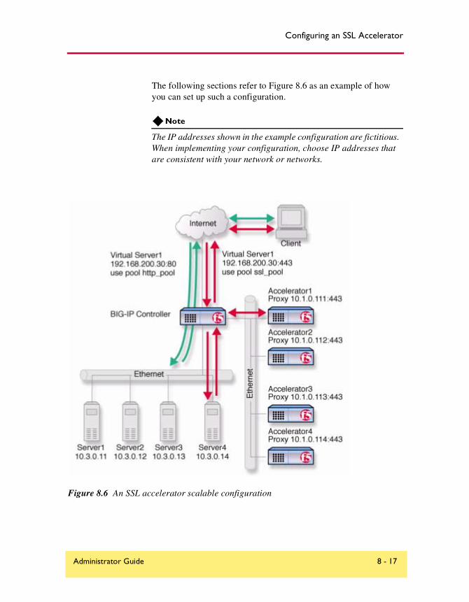
Configuring an SSL Accelerator
The following sections refer to Figure 8.6 as an example of how you can set up such a configuration.
Note
The IP addresses shown in the example configuration are fictitious. When implementing your configuration, choose IP addresses that are consistent with your network or networks.
Figure 8.6 An SSL accelerator scalable configuration
Administrator Guide 8 - 17
Chapter 8
Creating the scalable SSL accelerator configuration
To implement the scalable configuration, you must configure the BIG-IP Controller that load balances the servers and SSL accelerators, each SSL accelerator, and each node that handles connections from the SSL accelerator.
First, complete the following tasks on the BIG-IP Controller that you want to use to load balance connections to the SSL accelerators:
◆ Create two load balancing poolsOne pool load balances HTTP connections using the IP addresses of the web servers, the other pool load balances SSL connections to the SSL accelerators.
◆ Create virtual serversCreate virtual servers that reference the load balancing pools. Create one virtual server for the pool load balancing the SSL connections to the accelerators, and another virtual server for the pool that load balances the HTTP connections to the servers.
◆ Enable service 80 and service 443Enable service 80 and service 443 on the controller.
◆ Set the idle connection timerSet the idle connection timer for service 443.
Next, complete the following tasks for the SSL accelerators:
• Set up SSL gatewaysSet up an SSL gateway for each accelerator
• Enable service 443Enable service 443 for encrypted traffic.
Configuring the BIG-IP Controller that load balances the SSL accelerators
To configure the BIG-IP Controller that load balances the SSL accelerators, complete the following tasks on the BIG-IP Controller. This section describes how to complete each task.
8 - 18 BIG-IP® Controller 4.0

Configuring an SSL Accelerator
◆ Create two load balancing pools. One pool load balances HTTP connections using the IP addresses of the web servers, the other pool load balances SSL connections from the SSL accelerators.
◆ Create virtual servers that reference the load balancing pools.
◆ Enable port 80 and port 443 on the controller.
Creating load balancing pools
To create the load balancing pools required for the SSL accelerator configuration described in Figure 8.6, you need to create two pools.
◆ A load balancing pool for connections using the IP addresses of the content server nodes. For this example, the HTTP pool is named http_virtual. This pool contains the following members:Server1 (10.3.0.11)Server2 (10.3.0.12)Server3 (10.3.0.13)Server4 (10.3.0.14)
◆ A load balancing pool for SSL gateways. For this example, the SSL accelerator is named ssl_gateways. This pool contains the following members:accelerator1 (10.1.0.111)accelerator2 (10.1.0.112)accelerator3 (10.1.0.113)accelerator4 (10.1.0.114)
To create a pool using the Configuration utility
1. In the navigation pane, click Pools.The Pools screen opens.
2. Click the Add button.The Add Pool screen opens.
3. In the Add Pool screen, configure the load balancing method, persistence attributes, and members for the pool. For additional information about creating a pool, click the Help button.
Administrator Guide 8 - 19

Chapter 8
Configuration notes
• For this example, create an HTTP pool named http_virtual. This pool contains the following members:Server1 (10.3.0.11)Server2 (10.3.0.12)Server3 (10.3.0.13)Server4 (10.3.0.14)
• For this example, you could create an SSL accelerator pool named ssl_gateways. This pool contains the following members:accelerator1 (10.1.0.111)accelerator2 (10.1.0.112)accelerator3 (10.1.0.113)accelerator4 (10.1.0.114)
To define a pool from the command line
To define a pool from the command line, use the following syntax:b pool <pool_name> { member <member_definition> ... member
<member_definition>}
For example, if you want to create the pool http_virtual and the pool ssl_gateways, you would type the following commands:
b pool http_virtual { member 10.3.0.11:80 member 10.3.0.12:80 member 10.3.0.13:80 member 10.3.0.14:80 }
b pool ssl_gateways { member 10.1.0.111:443 member 10.1.0.112:443 member 10.1.0.113:443 member 10.1.0.114:443 }
Creating the virtual servers
Create a virtual server that references the pool that is load balancing the SSL connections, and another virtual server that references the pool that load balances the HTTP connections through the SSL accelerators.
8 - 20 BIG-IP® Controller 4.0

Configuring an SSL Accelerator
To define a standard virtual server that references a pool using the Configuration utility
1. In the navigation pane, click Virtual Servers.
2. Click the Add button.The Add Virtual Server screen opens.
3. Fill in the attributes for the virtual server. For additional information about this screen, click the Help button.
Configuration notes
• To create the configuration described in Figure 8.6, create a virtual server 192.168.200.30 on port 443 that references the pool of SSL accelerators.
• To create the configuration described in Figure 8.6, create a virtual server 192.168.200.30 on port 80 that references the pool of content servers.
To define a standard virtual server mapping from the command line
To define a standard virtual server from the command line, use the following syntax: b virtual <virt_IP>:<port> use pool <pool_name>
Note that you can use host names in place of IP addresses, and that you can use standard service names in place of port numbers.
To create the virtual servers for the configuration in Figure 8.6, you would type the following commands:b virtual 192.168.200.30:443 use pool ssl_gateways
b virtual 192.168.200.30:80 use pool http_virtual
Enabling ports 80 and 443 on the BIG-IP Controller
For security reasons, the BIG-IP Controller ports do not accept traffic until you enable them. In this configuration, the BIG-IP Controller accepts traffic on port 443 for SSL, and on port 80 for HTTP. For this configuration to work, you must enable port 80 and port 443.
Administrator Guide 8 - 21

Chapter 8
Use the following command to enable these ports:b service 80 443 tcp enable
Setting the idle connection timer for port 443
In this configuration, you should set the idle connection timer to clean up closed connections on port 443. You need to set an appropriate idle connection time-out value so that valid connections are not disconnected, and closed connections are cleaned up in a reasonable time.
To set the idle connection time-out using the Configuration utility
1. In the navigation pane, click Virtual Servers.
2. In the Virtual Servers list, click the virtual server you configured for SSL connections.The Virtual Server Properties screen opens.
3. Click the Virtual Ports tab.The Virtual Ports screen opens.
4. In the Port box, click the port. For the example in this section, choose 443.The Global Virtual Port Properties screen opens.
5. In the Idle connection timeout TCP (seconds) box, type a time-out value for TCP connections. The recommended time-out setting is 10 seconds.
6. In the Idle connection timeout UDP (seconds) box, type a time-out value for TCP connections. The recommended time-out setting is 10 seconds.
7. Click Apply.
To set the idle connection time-out from the command line
To set the idle connection time-outs, type the following commands:b service <port> timeout <seconds>
8 - 22 BIG-IP® Controller 4.0

Configuring an SSL Accelerator
The <seconds> value is the number of seconds a connection is allowed to remain idle before it is terminated. The <port> value is the port on the wildcard virtual server for which you are configuring out of path routing. The recommended value for the TCP and UDP connection timeouts is 10 seconds.
Configuring the SSL accelerators
The next step in the process is to configure the SSL accelerators. Complete the following tasks on each SSL accelerator:
• Set up an SSL gateway for each e-Commerce Controller
• Enable port 443
• Set the idle connection timer for port 443
Setting up an SSL gateway for each e-Commerce Controller
The first task you must complete on the SSL accelerator it to set up an SSL gateway for each e-Commerce Controller with the HTTP virtual server as target server.
To create an SSL gateway using the Configuration utility
1. In the navigation pane, click Proxies.The Proxies screen opens.
2. Click the Add button.The Add Proxy screen opens.
3. In the Add Proxy screen, configure the attributes you want to use with the proxy. For additional information about configuring a Proxy, click the Help button.
Configuration note
For this example, create the following proxies on Accelerator1, Accelerator2, Accelerator3, and Accelerator4, respectively: 10.1.0.111:443, 10.1.0.112:443, 10.1.0.113:443, and 10.1.0.114:443.
Administrator Guide 8 - 23

Chapter 8
To create an SSL gateway from the command line
Use the following command syntax to create an SSL gateway: b proxy <ip>:<port> [vlans add <vlan_list>] target server <ip>:<port> ssl
enable key <key> cert <cert>
For example, to create the SSL gateways accelerator1, accelerator2, accelerator3 and acceslerator4, you would use the following commands. Note that the target for each gateway is the HTTP virtual server 192.168.200.30:80.
b proxy 10.1.0.111:443 target server 192.168.200.30:80 ssl enable key my.server.net.key cert my.server.net.crt
b proxy 10.1.0.112:443 10.1.0.255 target server 192.168.200.30:80 ssl enable key my.server.net.key cert my.server.net.crt
b proxy 10.1.0.113:443 target server 192.168.200.30:80 ssl enable key my.server.net.key cert my.server.net.crt
b proxy 10.1.0.114:443 target server 192.168.200.30:80 ssl enable key my.server.net.key cert my.server.net.crt
Enabling port 443
For security reasons, the ports on the SSL accelerators do not accept traffic until you enable them. In this configuration, the SSL accelerator accepts traffic on port 443 for SSL. For this configuration to work, you must enable port 443. Use the following command to enable this port:b service 443 tcp enable
Additional configuration optionsWhenever you configure a BIG-IP Controller, you have a number of options.
◆ You have the option in all configurations to configure a redundant BIG-IP Controller for fail-over. Refer to Redundant Systems in the BIG-IP Reference Guide, Chapter 1, Configuring the BIG-IP Controller.
◆ All configurations have health monitoring options. Refer to Health Monitors in the BIG-IP Reference Guide, Chapter 1, Configuring the BIG-IP Controller.
8 - 24 BIG-IP® Controller 4.0

Configuring an SSL Accelerator
◆ When you create a pool, there is an option to set up persistence and a choice of load balancing methods. Refer to Pools in the BIG-IP Reference Guide, Chapter 1, Configuring the BIG-IP Controller.
Administrator Guide 8 - 25

9
Balancing Two-Way Traffic Across Firewalls
• Introducing two-way firewall load balancing
• Configuring two-way firewall load balancing
• Configuring routing to the internal network
• Creating pools for firewalls and servers
• Creating virtual servers for inbound traffic
• Creating virtual servers for outbound traffic
• Configuring administrative routing
• Additional configuration options
Balancing Two-Way Traffic Across Firewalls
Introducing two-way firewall load balancingThis chapter describes how to set up a configuration that load balances two types of traffic:
◆ Users on the Internet requesting information from a pair of enterprise servers behind the enterprise’s set of firewalls, generating inbound traffic.
◆ Users behind a set of firewalls requesting information from Internet servers, generating outbound traffic.
This type of configuration is appropriate for any enterprise that wants to provide information by way of the Internet, while limiting traffic to a specific service, and also wants to maintain a large intranet with fast access to the Internet for internal users.
This configuration calls for two BIG-IP Controllers:
◆ A BIG-IP Controller on the outside (that is, the side nearest the Internet) of the firewalls, to balance traffic inbound across the firewalls.
◆ A BIG-IP Controller on the inside (that is, the side nearest the enterprise servers) of the firewalls to balance traffic outbound across the firewalls, and also to balance traffic inbound across the server array.
Collectively, this is known as a firewall sandwich configuration, because the BIG-IP Controller are on either side of the fire walls sandwiching them. Figure 9.1 illustrates this type of configuration, and provides an example configuration for this entire chapter. Remember that this is just a sample: when creating your own configuration, you must use IP addresses, host names, and so on, that are applicable to your own network.
Note
All products except the BIG-IP e-Commerce Controller support this configuration.
Administrator Guide 9 - 1

Chapter 9
Figure 9.1 Load balancing two-way traffic
9 - 2 BIG-IP® Controller 4.0

Balancing Two-Way Traffic Across Firewalls
Configuring two-way firewall load balancingTo load balance enterprise servers as well as two-way traffic across a set of firewalls using a firewall sandwich configuration, you need to complete all the following tasks in order:
• Configure routing to the internal network.
• Create pools for firewalls and servers.
• Create virtual servers for inbound traffic.
• Create virtual servers for outbound traffic.
• Configure administrative routing.
The following sections provide details on how to set up this configuration, using the sample IP addresses and device names in Figure 9.1 as an example.
Configuring routing to the internal networkThe external router should route traffic bound for the network that includes your intranet by way of the external VLAN of the external BIG-IP Controller.
In Figure 9.1, the internal controller is BIG-IP Controller2, the network is 10.10.30.0/24, and the external address (or floating self IP address for redundant system) of the external controller is 10.10.10.1. Thus, a command to configure this routing might be:Route add -net 10.10.30.0 -gateway 10.10.10.1
The exact syntax of this command depends on the type of router.
Creating pools for firewalls and serversTo use this configuration, you must create load balancing pools. You will create three pools.
Administrator Guide 9 - 3

Chapter 9
◆ To load balance incoming requests across the external interfaces of your firewalls, you create a pool that includes these external interfaces.
◆ Because requests that pass through the firewalls must be load balanced to the enterprise servers, you create a pool that includes these enterprise servers.
◆ Outgoing requests must be balanced across the internal interfaces of your firewalls, so you create a pool that includes these internal interfaces.
Creating a pool for outside firewall interfaces
When using this configuration, you first create the pool for the outside addresses of the firewalls on the outside BIG-IP Controller.
To create the pool using the Configuration utility
1. In the navigation pane, click Pools.The Pools screen opens.
2. Click the Add button.The Add Pool screen opens.
3. Configure the following attributes on the Add Pool screen. For additional information about creating a pool, click the Help button.
Configuration notes
To create the configuration shown in Figure 9.1:
• Create a pool named firewalls_outside.
• Add each firewall from the example, 10.10.20.4, 10.10.20.5, and 10.10.20.6, to the pool. For each firewall you add to the pool, specify port 0.
9 - 4 BIG-IP® Controller 4.0

Balancing Two-Way Traffic Across Firewalls
To create the pool from the command line
Use the bigpipe pool command to create the pool:b pool <pool name> { member <Firewall1>:0 member <Firewall2>:0 member
<Firewall3>:0 }
In Figure 9.1, for example, the pool for the outside addresses is firewalls_outside, and the outside addresses are 10.10.20.4, 10.10.20.5, and 10.10.20.6. Thus, the command would be:
b pool firewalls_outside { member 10.10.20.4:0 member 10.10.20.5:0 member 10.10.20.6:0 }
Creating a pool for inside firewall interfaces
Next, create a pool for the internal addresses of your firewalls on the inside BIG-IP Controller BIG-IP 2. Use the Configuration utility, or the bigpipe pool command, as you did to create the pool for the outside firewall addresses. Choose a pool name appropriate for this pool.
To create the pool using the Configuration utility
1. In the navigation pane, click Pools.The Pools screen opens.
2. Click the Add button.The Add Pool screen opens.
3. Configure the following attributes on the Add Pool screen. For additional information about creating a pool, click the Help button.
Configuration notes
When you create the configuration shown in Figure 9.1:
• Create a pool named firewalls_inside.
• Add each firewall from the example, 10.10.30.4, 10.10.30.5, and 10.10.30.6, to the pool. For each firewall you add to the pool, specify port 0.
Administrator Guide 9 - 5

Chapter 9
To create the pool from the command line
Use the bigpipe pool command to create the pool:b pool <pool name> { member <Firewall1>:0 member <Firewall2>:0 member
<Firewall3>:0 }
To implement the configuration shown in Figure 9.1, you create this pool on BIG-IP 2. In this example, the pool for the inside addresses is firewalls_inside, and the inside addresses are 10.10.30.4, 10.10.30.5, and 10.10.30.6. Thus, the command to implement this configuration would be:
b pool firewalls_inside { member 10.10.30.4:0 member 10.10.30.5:0 member 10.10.30.6:0 }
Creating a pool for servers
Finally, create the pool for the nodes that handle requests to your enterprise servers on the inside BIG-IP Controller BIG-IP 2. Use the Configuration utility, or the bigpipe pool command, as you did to create the firewall pools. Choose a pool name appropriate for this pool.
To create the pool using the Configuration utility
1. In the navigation pane, click Pools.The Pools screen opens.
2. Click the Add button.The Add Pool screen opens.
3. Configure the following attributes on the Add Pool screen. For additional information about creating a pool, click the Help button.
Configuration notes
When you create the configuration shown in Figure 9.1:
• Create a pool named servers.
• Add the servers 10.10.40.4 and 10.10.40.5 to the pool. For each server, specify port 0.
9 - 6 BIG-IP® Controller 4.0

Balancing Two-Way Traffic Across Firewalls
To create the pool from the command line
Use the bigpipe pool command to create the pool:b pool <pool name> { member <Server1>:0 member <Server2>:0 }
To implement the configuration shown in Figure 9.1, you create this pool on BIG-IP 2. In this example, the pool for the server addresses is servers, and the server addresses are 10.10.40.4 and 10.10.40.5. Thus, the command to implement this configuration would be:
b pool servers { member 10.10.40.4:80 member 10.10.40.5:80 }
Creating virtual servers for inbound trafficAfter you define the pools for the outer interfaces of the firewalls, you can define virtual servers on the BIG-IP Controllers to load balance inbound connections. To do this you:
◆ Create a network virtual server on the outside BIG-IP Controllers BIG-IP 1 to load balance the firewalls. A network virtual server is a virtual server that handles a whole network range, instead of just one IP address.
◆ Create a standard virtual server on the inside BIG-IP Controller BIG-IP 2 to load balance the enterprise servers.
Creating a network virtual server to load balance the firewalls
Because the outside BIG-IP Controller load balances inbound connections across the outside interfaces of the firewalls, you need to create a virtual server on that system. This virtual server will reference the pool you created in Creating a pool for outside firewall interfaces, on page 9-4 that contains these outside firewall interfaces.
In order to accommodate potential multiple virtual servers for your enterprise servers, create a network virtual server. A network virtual server is a virtual server that handles a whole network
Administrator Guide 9 - 7

Chapter 9
range, instead of just one IP address. For example, in Figure 9.1, the virtual server 10.10.30.0 load balances traffic across the firewall set to all virtual servers on the 10.10.30.0/24 network.
To create a network virtual server using the Configuration utility
1. In the navigation pane, click Virtual Servers.The Virtual Servers screen opens.
2. Click the Add button.The Add Virtual Server screen opens.
3. Configure the appropriate attributes on the Add Virtual Server screen. For additional information about configuring a virtual server, click the Help button.
Configuration note
When you create the configuration shown in Figure 9.1:
• Add a virtual server with address 10.10.30.0 and port 0 (this designates a wildcard virtual server).
• In the Pool list, select firewalls_outside (having created the firewalls_outside pool in Creating a pool for outside firewall interfaces, on page 9-4).
To create a network virtual server from the command line
Use the bigpipe virtual command to configure the virtual server to use the pool that contains the outside addresses of the firewalls:b virtual <virt_ip>:<service> use pool <pool name>
Repeat this command for each service you want to configure. To implement the configuration shown in Figure 9.1, you use the command:b virtual 10.10.30.0 use pool firewall_outsides
9 - 8 BIG-IP® Controller 4.0

Balancing Two-Way Traffic Across Firewalls
Enhancing security for this configuration
To supplement the security offered by your firewalls, you may want to create a standard virtual server rather than a network virtual server. For example, in the configuration shown in Figure 9.1, you really only need a virtual server for 10.10.30.9. In this configuration, using a standard virtual server would reduce the number of accessible addresses from 254 to 1.
◆ To create a standard virtual server to enhance the security of the configuration shown in Figure 9.1 using the Configuration utility, follow the instructions in To create a network virtual server using the Configuration utility, on page 9-8. Substitute 10.10.30.9 for the Address attribute, and 80 for Port.
◆ To create a port-specific virtual server to enhance the security of the configuration shown in Figure 9.1 from the command line, use the bigpipe virtual command as explained in To create a network virtual server from the command line, on page 9-8. The command would be:
b virtual 10.10.30.9:80 use pool firewall_outsides
Creating a standard virtual server to load balance intranet servers
After you configure the outside BIG-IP Controller BIG-IP 1 to handle inbound traffic, configure the inside BIG-IP Controller BIG-IP 2 to load balance the enterprise servers.
Use the Configuration utility, or the bigpipe virtual command, as you did to create the wildcard virtual server for the inside BIG-IP Controller. Instead of using a wildcard IP address, use a standard IP address and pool appropriate for your network.
To create a standard virtual server using the Configuration utility
1. In the navigation pane, click Virtual Servers.
Administrator Guide 9 - 9

Chapter 9
2. Click Add Virtual Server.The Add Virtual Server screen opens.
3. Configure the appropriate attributes on the Add Virtual Server screen. For additional information about configuring a virtual server, click the Help button.
4. In the Pool list, select the pool you want to apply to the virtual server. For example, to implement the configuration shown in Figure 9.1, you would choose servers (having created the servers pool in Creating a pool for servers, on page 9-6).
Configuration notes
When you create the configuration shown in Figure 9.1:
• Add a virtual server with address 10.10.30.9, port 80.
• In the Pool list, select firewalls_outside (having created the firewalls_outside pool in Creating a pool for servers, on page 9-6).
To create a standard virtual server from the command line
Use the bigpipe virtual command to configure the virtual server to use the pool that contains the outside addresses of the firewalls:b virtual <virt_ip>:<service> use pool <pool name>
For example, to use the bigpipe virtual command to implement the configuration shown in Figure 9.1, the command would be:b virtual 10.10.30.9:80 use pool server_pool
Creating virtual servers for outbound trafficAfter you define the pools for the internal interfaces of the firewalls, you can define virtual servers on the BIG-IP Controllers to load balance outbound connections.
To do this you:
9 - 10 BIG-IP® Controller 4.0

Balancing Two-Way Traffic Across Firewalls
◆ Create a wildcard virtual server on the inside BIG-IP Controller to balance traffic outbound to the firewalls.
◆ Create a forwarding wildcard virtual server on the outside BIG-IP Controller to forward traffic to the Internet. A forwarding virtual server is a virtual server that merely forwards traffic, rather than balancing it across nodes.
Creating a wildcard virtual server for balancing traffic to the firewalls
To configure the inside BIG-IP Controller for outbound connections, create a wildcard virtual server that accepts all traffic from the internal network, then load balances the traffic through the firewalls. After you create this wildcard virtual server, you must disable it on the external VLAN.
To create a wildcard virtual server using the Configuration utility
1. In the navigation pane, click Virtual Servers.
2. Click the Add button.The Add Virtual Server screen opens.
3. Configure the following attributes on the Add Virtual Server screen. For additional information about configuring a virtual server, click the Help button.
Configuration note
To create the configuration shown in Figure 9.1, configure the wildcard virtual server 0.0.0.0:0 and use the pool firewalls_inside.
To create a wildcard virtual server from the command line
Use the bigpipe virtual command to configure the virtual server to use the pool that contains the outside addresses of the firewalls:b virtual 0.0.0.0:0 use pool <pool name>
Administrator Guide 9 - 11

Chapter 9
To use the bigpipe virtual command to create the virtual server and disable it on the external VLAN as show in the configuration in Figure 9.1, type the following command:b virtual 0.0.0.0:0 use pool firewall_insides vlans disable external
Creating a forwarding wildcard virtual server to forward traffic to the Internet
After the appropriate firewall has processed outbound traffic, you want the outside BIG-IP Controller to forward the traffic to the Internet. To accomplish this, create a wildcard virtual server as you did in Creating a wildcard virtual server for balancing traffic to the firewalls, on page 9-11, using either the Configuration utility or the command line.
◆ If you use the Configuration utility, use the address and port 0.0.0.0:0, and select Forwarding in the Resources section.
◆ From the command line, to implement the configuration shown in Figure 9.1, you type:
b virtual 0.0.0.0:0 forward vlans external disable
Enhancing security for this configuration
In some situations, you may want to limit the types of traffic that can pass outbound to the Internet. You can use port-specific wildcard virtual servers to restrict traffic in this manner. While a standard wildcard virtual server forwards all traffic, a port-specific wildcard virtual server forwards traffic specific to only the specified port. For more information, see Virtual servers in the BIG-IP Reference Guide, Chapter 1, Configuring the BIG-IP Controller.
9 - 12 BIG-IP® Controller 4.0

Balancing Two-Way Traffic Across Firewalls
To create a port-specific wildcard server using the Configuration utility
Follow the instructions detailed in To create a wildcard virtual server using the Configuration utility, on page 9-11, with these exceptions:
◆ In step 3, when you configure the Port attribute, choose the port to which you want outgoing traffic to be limited for that virtual server.
◆ Complete the rest of the steps as detailed on page 9-11, then repeat the process for any other ports you want to be accessible to outgoing traffic.
For example, to implement the configuration shown in Figure 9.1, to limit the traffic forwarded to HTTP and FTP, you would follow the instructions in To create a wildcard virtual server using the Configuration utility three times. That is, once for each of three port-specific virtual servers, entering respectively 80, 20, and 21 for the Port attribute.
To create a port-specific wildcard server from the command line
To create a port-specific wildcard server, use the bigpipe virtual command as you did in To create a network virtual server from the command line, on page 9-8. For the sample port number, substitute the number of the port to which you want to limit access.
For example, in the configuration shown in Figure 9.1, to limit the traffic forwarded to HHTP and FTP, you replace the command in the preceding section with the following commands:b virtual 0.0.0.0:80 use pool firewall
b virtual 0.0.0.0:20 use pool firewall
b virtual 0.0.0.0:21 use pool firewall
Administrator Guide 9 - 13
Chapter 9
Configuring administrative routingIn order to administer the outside BIG-IP Controller from the inside BIG-IP Controller and vice versa, you need to create routes between the systems, using the firewalls as gateways.
To implement the configuration shown in Figure 9.1, you use the following commands on BIG-IP Controllers BIG-IP 1:route add -host 10.10.30.1 -gateway 10.10.20.4
If BIG-IP 1 is a redundant pair with 10.10.30.2 and 10.10.30.3 as its external addresses and 10.10.30.1 as their floating alias:route add -host 10.10.30.1 -gateway 10.10.20.4
route add -host 10.10.30.2 -gateway 10.10.20.5
route add -host 10.10.30.3 -gateway 10.10.20.6
To complete the configuration, you use the following commands on BIG-IP Controller BIG-IP 2:route add -host 10.10.20.1 -gateway 10.10.30.4
If BIG-IP 2 is a redundant pair with 10.10.20.2 and 10.10.20.3 as its internal addresses and 10.10.20.1 as their floating alias:route add -host 10.10.20.1 -gateway 10.10.30.4
route add -host 10.10.20.2 -gateway 10.10.30.5
route add -host 10.10.20.3 -gateway 10.10.30.6
Additional configuration optionsWhenever you configure a BIG-IP Controller, you have a number of options:
◆ You have the option in all configurations to configure a redundant BIG-IP Controller for fail-over. Refer to Redundant Systems in the BIG-IP Reference Guide, Chapter 1, Configuring the BIG-IP Controller.
◆ All configurations have health monitoring options. Refer to Health Monitors in the BIG-IP Reference Guide, Chapter 1, Configuring the BIG-IP Controller.
9 - 14 BIG-IP® Controller 4.0

Balancing Two-Way Traffic Across Firewalls
◆ When you create a pool, there is an option to set up persistence and a choice of load balancing methods. Refer to Pools in the BIG-IP Reference Guide, Chapter 1, Configuring the BIG-IP Controller.
Administrator Guide 9 - 15

10
Load Balancing a Cache Array for Local Server Acceleration
• Introducing local server acceleration
• Configuring local acceleration
• Creating pools
• Creating a cache rule
• Creating a virtual server
• Configuring for intelligent cache population
• Additional configuration options

Load Balancing a Cache Array for Local Server Acceleration
Introducing local server accelerationThis chapter explains how to set up a local server acceleration configuration, in which a BIG-IP Controller uses content-aware traffic direction to enhance the efficiency of an array of cache servers that cache content for a local web server. This type of configuration is useful for any enterprise that wants to improve the speed with which it responds to content requests from users on the Internet.
Note
All products except the BIG-IP LoadBalancer and BIG-IP e-Commerce Controller support this configuration.
The configuration detailed in this chapter uses the following BIG-IP Controller features:
◆ Cacheable content determinationWith cacheable content determination you can determine the type of content you cache on the basis of any combination of elements in the header of an HTTP request.
◆ Content affinityContent affinity ensures that a given subset of content remains associated with a given cache to the maximum extent possible, even when cache servers become unavailable, or are added or removed. This feature also maximizes efficient use of cache memory.
◆ Hot content load balancingHot content load balancing identifies hot, or frequently requested, content on the basis of number the number of requests in a given time period for a given hot content subset. A hot content subset is different from, and typically smaller than, the content subsets used for content striping. Requests for hot content are redirected to a cache server in the hot pool, a designated group of cache servers. This feature maximizes the use of cache server processing power without significantly affecting the memory efficiency gained by content affinity.
Administrator Guide 10 - 1

Chapter 10
◆ Intelligent cache population Intelligent cache population allows caches to retrieve content from other caches in addition to the origin web server. This feature is useful only when working with non-transparent cache servers, which can receive requests that are destined for the cache servers themselves, as opposed to transparent cache servers, which can intercept requests destined for a web server. Intelligent cache population minimizes the load on the origin web server and speeds cache population.
Maximizing memory or processing power
From the time you implement a cache rule until such time a hot content subset becomes hot, the content is divided across your cache servers, so that no two cache servers contain the same content. In this way, efficient use of the cache servers’ memory is maximized.
After a hot content subset becomes hot, requests for any content contained in that subset are load balanced, so that, ultimately, each cache server contains a copy of the hot content. The BIG-IP Controller distributes requests for the hot content among the cache servers. This way, efficient use of the cache servers’ processing power is maximized.
Thus, for a particular content item, the BIG-IP Controller maximizes either cache server memory (when the content is cool) or cache server processing power (when the content is hot), but not both at the same time. The fact that content is requested with greatly varying frequency enables the cache statement rule to evaluate and select the appropriate attribute to maximize for a given content subset.
10 - 2 BIG-IP® Controller 4.0
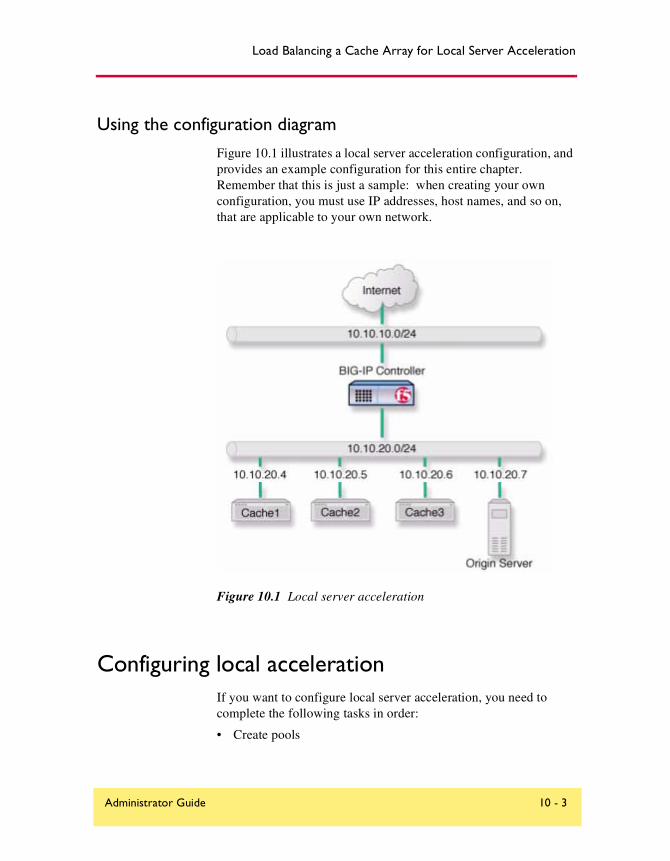
Load Balancing a Cache Array for Local Server Acceleration
Using the configuration diagram
Figure 10.1 illustrates a local server acceleration configuration, and provides an example configuration for this entire chapter. Remember that this is just a sample: when creating your own configuration, you must use IP addresses, host names, and so on, that are applicable to your own network.
Figure 10.1 Local server acceleration
Configuring local accelerationIf you want to configure local server acceleration, you need to complete the following tasks in order:
• Create pools
Administrator Guide 10 - 3

Chapter 10
• Create a cache rule
• Create a virtual server
• Configure for intelligent cache population
Each of the following sections explains one of these tasks, and shows how you would perform the tasks in order to implement the configuration shown in Figure 10.1. Note that in this example, as in all examples in this guide, we use only non-routable IP addresses. In a real topology, the appropriate IP addresses would have to be routable on the Internet.
Creating poolsTo use the local server acceleration configuration, you need to create three sets of load balancing pools. You create pools for your origin server (the web server on which all your content resides), for your cache servers, and for your hot, or frequently requested, content servers, which may or may not be cache servers. A pool is a group of devices to which you want the BIG-IP Controller to direct traffic. For more information about pools, refer to Pools in the BIG-IP Reference Guide, Chapter 1, Configuring the BIG-IP Controller.
You will create these pools:
◆ Cache server poolThe BIG-IP Controller directs all cacheable requests bound for your web server to this pool, unless a request is for hot content.
◆ Origin server poolThis pool includes your origin web server. Requests are directed to this pool when:
• The request is for non-cacheable content; that is, content that is not identified in the cacheable content expression part of a cache statement. For more information, see Using a cacheable content expression, on page 10-9.
10 - 4 BIG-IP® Controller 4.0

Load Balancing a Cache Array for Local Server Acceleration
• The request is from a cache server that does not yet contain the requested content, and no other cache server yet contains the requested content.
• No cache server in the cache pool is available.
◆ Hot cache servers poolIf a request is for frequently requested content, the BIG-IP Controller directs the request to this pool.
Note
While the configuration shown in Figure 10.1 implements a hot cache servers pool, this pool is not required if you want to use the content determination and content affinity features. However, you must implement this pool if you want to use the hot content load balancing or intelligent cache population features.
Creating a pool for the cache servers
First, create a pool for the cache servers. Use either the Configuration utility or the command line to create this pool.
To create a cache server pool using the Configuration utility
1. In the navigation pane, click Pools.The Pools screen opens.
2. Click the Add button.The Add Pool screen opens.
3. In the Add Pool screen, configure attributes required for the cache servers you want to add to the pool. For additional information about configuring a pool, click the Help button.
Configuration notes
When you create the configuration shown in Figure 10.1:
• Create a pool named cache_servers.
Administrator Guide 10 - 5

Chapter 10
• Add each cache server from the example, 10.10.20.4, 10.10.20.5, and 10.10.20.6, to the pool. For each cache server you add to the pool, specify port 80, which means this cache server accepts traffic for the HTTP service only.
To create a cache server pool from the command line
To define a pool from the command line, use the following syntax:b pool <pool_name> { lb_method <lb_method> member <member_definition> ...
member <member_definition> }
For example, to implement the configuration shown in Figure 10.1, you use the command:
b pool cache_servers { lb_method round_robin member 10.10.20.4:80 member 10.10.20.5:80 member 10.10.20.6:80 }
Creating a pool for the origin server
Next, create a pool for your origin server. Use either the Configuration utility or the b pool command, as you did to create the pool for the cache servers.
To create an origin server pool using the Configuration utility
1. In the navigation pane, click Pools.The Pools screen opens.
2. Click the Add button.The Add Pool screen opens.
3. In the Add Pool screen, configure attributes required for the cache servers you want to add to the pool. For additional information about configuring a pool, click the Help button.
Configuration notes
To create the configuration shown in Figure 10.1:
• Create a pool named origin_server.
10 - 6 BIG-IP® Controller 4.0
Load Balancing a Cache Array for Local Server Acceleration
• Add the origin server from the example (10.10.20.7) to the pool and specify port 80, which means the server accepts traffic for the HTTP service only.
To create an origin server pool from the command line
To define a pool from the command line, use the following syntax:b pool <pool_name> { lb_method <lb_method> member <member_definition> ...
member <member_definition> }
For example, to implement the configuration shown in Figure 10.1, you would use the command:
b pool origin_server { lb_method round_robin member 10.10.20.7:80 }
Creating a pool for hot content
The last step in creating pools is to create a pool for hot content. Use either the Configuration utility or the command line to create this pool, as in the previous sections.
To create a hot content pool using the Configuration utility
1. In the navigation pane, click Pools.The Pools screen opens.
2. Click the Add button.The Add Pool screen opens.
3. In the Add Pool screen, configure the attributes required for the cache servers you want to add to the pool. For additional information about configuring a pool, click the Help button.
Configuration notes
When you create the configuration shown in Figure 10.1:
• Create a pool named hot_cache_servers.
Administrator Guide 10 - 7

Chapter 10
• Add each cache server from the example, 10.10.20.4, 10.10.20.5, and 10.10.20.6, to the pool. For each cache server you add to the pool, specify port 80, which means this cache server accepts traffic for the HTTP service only.
To create a hot content pool from the command line
To define a pool from the command line, use the following syntax:b pool <pool_name> { lb_method <lb_method> member <member_definition> ...
member <member_definition> }
To implement the configuration shown in Figure 10.1, you would use the command:
b pool hot_cache_servers { lb_method round_robin member 10.10.20.4:80 member 10.10.20.5:80 member 10.10.20.6:80 }
Note
If you have the hot content pool and the cache servers pool reference the same nodes, it enables use of the intelligent cache population feature.
Creating a cache ruleA cache rule is a specific type of rule. A rule establishes criteria by which a BIG-IP Controller directs traffic. A cache rule determines where and how the BIG-IP Controller directs content requests in order to maximize the efficiency of your cache server array and of your origin web server.
A cache rule includes a cache statement, which is composed of a cacheable content expression and two attributes. An attribute is a variable that the cache statement uses to direct requests. It can also include several optional attributes.
A cache statement may be either the only statement in a rule, or it may be nested in a rule within an if statement.
10 - 8 BIG-IP® Controller 4.0

Load Balancing a Cache Array for Local Server Acceleration
Using a cacheable content expression
The cacheable content expression determines whether the BIG-IP Controller directs a given request to the cache server or to the origin server, based on evaluating variables in the HTTP header of the request.
Any content that does not meet the criteria in the cacheable content expression is deemed non-cacheable.
For example, in the configuration illustrated in this chapter, the cacheable content expression includes content having the file extension .html or .gif. The BIG-IP Controller considers any request for content having a file extension other than .html or .gif to be non-cacheable, and sends such requests directly to the origin server.
For your configuration, you may want to cache any content that is not dynamically generated.
Working with required attributes
The cache rule must include the following attributes:
◆ origin_poolSpecifies a pool of servers that contain original copies of all content. Requests are load balanced to this pool when any of the following are true:
• The requested content does not meet the criteria in the cacheable content condition.
• No cache server is available.
• The BIG-IP Controller is redirecting a request from a cache server that did not have the requested content.
◆ cache_poolSpecifies a pool of cache servers to which requests are directed in a manner that optimizes cache performance.
Administrator Guide 10 - 9

Chapter 10
Using optional attributes
The attributes in this section apply only if you are using the hot content load balancing feature.
Note
In order to use the intelligent cache population feature, the cache_pool and the hot_pool must either be the same pool, or different pools referencing the same nodes.
◆ hot_poolSpecifies a pool of cache servers to which requests are load balanced when the requested content is hot. The hot_pool attribute is required if any of the following attributes is specified.
◆ hot_thresholdSpecifies the minimum number of requests for content in a given hot content set that causes the content set to change from cool to hot at the end of the period.If you specify a value for hot_pool, but do not specify a value for this variable, the cache statement uses a default hot threshold of 100 requests.
◆ cool_thresholdSpecifies the maximum number of requests for content in a given hot content set that causes the content set to change from hot to cool at the end of the hit period. If you specify a variable for hot_pool, but do not specify a value for this variable, the cache statement uses a default cool threshold of 10 requests.
◆ hit_periodSpecifies the period in seconds over which to count requests for particular content before determining whether to change the content demand status (hot or cool) of the content. If you specify a value for hot_pool, but do not specify a value for this variable, the cache statement uses a default hit period of 60 seconds.
10 - 10 BIG-IP® Controller 4.0

Load Balancing a Cache Array for Local Server Acceleration
◆ content_hash_sizeSpecifies the number of units, or hot content subsets, into which the content is divided when determining whether content demand status is hot or cool. The requests for all content in a given subset are summed, and a content demand status (hot or cool) is assigned to each subset. The content_hash_size should be within the same order of magnitude as the actual number of requests possible. For example, if the entire site is composed of 500,000 pieces of content, a content_hash_size of 100,000 would be typical. If you specify a value for hot_pool, but do not specify a value for this variable, the cache statement uses a default hash size of 1028 subsets.
Setting content demand status
Content demand status is a measure of the frequency with which a given hot content subset is requested. Content demand status, which is either hot or cool, is applicable only when using the hot content load balancing feature. For a given hot content subset, content demand status is cool from the time the cache rule is implemented until the number of requests for the subset exceeds the hot_threshold during a hit_period. At this point content demand status for the subset becomes hot, and requests for any item in the subset are load balanced to the hot_pool. Content demand status remains hot until the number of requests for the subset falls below the cool_threshold during a hit_period, at which point the content demand status becomes cool. The BIG-IP Controller the directs requests for any item in the subset to the appropriate server in the cache_pool until such time as the subset becomes hot again.
To create a cache rule using the Configuration utility
1. In the navigation pane, click Rules.The Rules screen opens.
2. Click the Add button.The Add Rule screen opens.
Administrator Guide 10 - 11

Chapter 10
3. In the Add Rule screen, type the cache statement. For example, given the configuration shown in Figure 10.1, to cache all content having either the file extension .html or .gif, you would type:
rule cache_rule { cache ( http_uri ends_with "html" or http_uri ends_with "gif" ) { origin_pool origin_server cache_pool cache_servers hot_pool hot_cache_servers } }
4. Click the Add button.
To create a cache statement rule from the command line
To create a cache statement rule from the command line, use the following syntax:
b ’rule <rule_name> { cache ( <condition> ) { origin_pool <origin_pool_name> cache_pool <cache_pool_name> hot_pool <hot_pool_name> hot_threshold <hot_threshold_value> cool_threshold <cool_threshold_value> hit_period <hit_period_value> content_hash_size <content_hash_size_value> } }’
For example, given the configuration shown in Figure 10.1, to cache all content having the file extension .html or .gif, you would use the bigpipe command:
b ’rule cache_rule { cache ( http_uri ends_with "html" or http_uri ends_with "gif" ) { origin_pool origin_server cache_pool cache_servers hot_pool hot_cache_servers } }’
Creating a virtual serverNow that you have created pools and a cache rule to determine how the BIG-IP Controller will distribute traffic in the configuration, you need to create a virtual server to use this rule and these pools. For this virtual server, use the host name or IP address that Internet clients use to request content from your site.
10 - 12 BIG-IP® Controller 4.0
Load Balancing a Cache Array for Local Server Acceleration
To create a virtual server using the Configuration utility
1. In the navigation pane, click Virtual Servers.
2. Click the Add button.The Add Virtual Server screen opens.
3. In the Add Virtual Server screen, configure the attributes you want to use with the virtual server. For additional information about configuring a virtual server, click the Help button.
Configuration notes
When you create the configuration shown in Figure 10.1:
• Add a virtual server with address 10.10.10.4 and port 80 (this means the virtual server accepts traffic for the HTTP service only).
• Add the rule cache_rule.
To create a virtual server from the command line
Use the bigpipe virtual command to configure the virtual server to use the pool that contains the outside addresses of the firewalls:b virtual <virt_ip>:<service> use rule <rule name>
To implement the configuration shown in Figure 10.1, you use the command:b virtual 10.10.10.4:80 use rule cache_rule
Configuring for intelligent cache populationYour cache rule routes a request to the appropriate cache server. However, the cache server will not have the requested content if the content has expired, or if the cache server is receiving a request for this content for the first time. If the cache does not have the requested content, the cache initiates a miss request (that is, a request resulting from a request for content a cache does not have) for this content. The miss request goes to the origin server
Administrator Guide 10 - 13
Chapter 10
specified in the configuration of the cache or to another cache server. If you want to allow intelligent cache population, you should configure the cache with its origin server set to be the virtual server on the BIG-IP Controller, so that the cache sends miss requests to the internal interface of the BIG-IP Controller. The BIG-IP Controller translates the destination of the request, and sends the request to either the origin server or another cache server that already has the requested content.
To ensure that the origin server or cache server responds to the BIG-IP Controller rather than to the original cache server that generated the miss request, the BIG-IP Controller also translates the source of the miss request to the translated address and port of the associated Secure Network Address Translation (SNAT) connection.
In order to use this solution, you must create a SNAT on the BIG-IP Controller.
Configuring a SNAT
A Secure Network Address Translation (SNAT) translates the address of a packet from the cache server to the address you specify. For more information about SNATs, see SNATs in the BIG-IP Reference Guide, Chapter 1, Configuring the BIG-IP Controller.
To configure a SNAT mapping using the Configuration utility
1. In the navigation pane, click SNATs.The SNATs screen opens.
2. Click the Add button.The Add SNAT screen opens.
3. In the Add SNAT screen, configure the attributes required for the SNAT you want to add. For additional information about configuring a pool, click the Help button.
10 - 14 BIG-IP® Controller 4.0

Load Balancing a Cache Array for Local Server Acceleration
Configuration note
• When you create the configuration shown in Figure 10.1, use the translation address 10.10.10.5.
To configure a SNAT mapping from the command line
The bigpipe snat command defines one SNAT for one or more node addresses. b snat map <orig_ip>... to <snat_ip>
For example, to implement the configuration shown in Figure 10.1, you use the command:
b snat map 10.10.20.4 10.10.20.5 10.10.20.6 to 10.10.10.5
Additional configuration optionsWhenever you configure a BIG-IP Controller, there are a number of options available to you:
◆ You have the option in all configurations to configure a redundant BIG-IP Controller for fail-over. Refer to Redundant Systems in the BIG-IP Reference Guide, Chapter 1, Configuring the BIG-IP Controller.
◆ All configurations have health monitoring options. Refer to Health Monitors in the BIG-IP Reference Guide, Chapter 1, Configuring the BIG-IP Controller.
◆ When you create a pool, there is an option to set up persistence and a choice of load balancing methods. Refer to Pools in the BIG-IP Reference Guide, Chapter 1, Configuring the BIG-IP Controller.
Administrator Guide 10 - 15
11
Load Balancing a Cache Array for Remote Server Acceleration
• Introducing remote server acceleration
• Configuring remote server acceleration
• Creating pools
• Creating a cache rule
• Creating a virtual server
• Configuring for intelligent cache population
• Additional configuration options

Load Balancing a Cache Array for Remote Server Acceleration
Introducing remote server accelerationThis chapter explains how to set up a remote server acceleration configuration, in which a BIG-IP Controller uses content-aware traffic direction to enhance the efficiency of an array of cache servers that cache content for a remote web server.
Note
All products except the BIG-IP LoadBalancer Controller support this configuration.
Figure 11.1 illustrates the remote server acceleration configuration, and provides an example configuration for this entire chapter. Remember that this is just a sample: when creating your own configuration, you must use IP addresses, host names, and so on, that are applicable to your own network.
Figure 11.1 Remote server acceleration
Administrator Guide 11 - 1

Chapter 11
This configuration is similar to the configuration discussed in Chapter 10, Load Balancing a Cache Array for Local Server Acceleration. The difference is that, in this configuration, the cache servers reside on an intranet network, while the origin web server resides on the Internet; in the local server acceleration configuration, the origin web server and the cache servers all reside on the intranet. The remote server acceleration configuration is appropriate for any enterprise in which the cache server network and web server network are separated, and you want maximum speed and efficiency from both the cache servers and web server.
The configuration detailed in this chapter uses the following BIG-IP Controller features:
◆ Cacheable content determinationWith cacheable content determination, you can determine the type of content you cache on the basis of any combination of elements in the header of an HTTP request.
◆ Content affinityContent affinity ensures that a given subset of content remains associated with a given cache to the maximum extent possible, even when cache servers become unavailable, or are added or removed. This feature also maximizes efficient use of cache memory.
◆ Hot content load balancingHot content load balancing identifies hot, or frequently requested, content on the basis of number of requests in a given time period for a given hot content subset. A hot content subset is different from, and typically smaller than, the content subsets used for content striping. Requests for hot content are redirected to a cache server in the hot pool, a designated group of cache servers. This feature maximizes the use of cache server processing power without significantly affecting the memory efficiency gained by content affinity.
◆ Intelligent cache population Intelligent cache population allows caches to retrieve content from other caches in addition to the origin web server. This feature is useful only when working with non-transparent cache servers, which can receive requests that are destined for the cache servers themselves, as opposed to transparent cache
11 - 2 BIG-IP® Controller 4.0
Load Balancing a Cache Array for Remote Server Acceleration
servers, which can intercept requests destined for a web server. Intelligent cache population minimizes the load on the origin web server and speeds cache population.
Maximizing memory or processing power
From the time you implement a cache rule until such time as a hot content subset becomes hot, the content is divided across your cache servers, so that no two cache servers contain the same content. In this way, efficient use of the cache servers’ memory is maximized.
After a hot content subset becomes hot, requests for any content contained in that subset are load balanced, so that, ultimately, each cache server contains a copy of the hot content. The BIG-IP Controller distributes requests for the hot content among the cache servers. In this way, efficient use of the cache servers’ processing power is maximized.
Thus, for a particular content item, the BIG-IP Controller maximizes either cache server memory (when the content is cool) or cache server processing power (when the content is hot), but not both at the same time. The fact that content is requested with greatly varying frequency enables the cache statement rule to evaluate and select the appropriate attribute to maximize for a given content subset.
Configuring remote server accelerationTo configure remote server acceleration, complete the following tasks in order:
• Create pools
• Create a cache rule
• Create a virtual server
• Configure for intelligent cache population
Administrator Guide 11 - 3

Chapter 11
Each of the following sections explains one of these tasks, and shows how you would perform the tasks in order to implement the configuration shown in Figure 11.1. Note that in this example, as in all examples in this guide, we use only non-routable IP addresses. In a real topology, the appropriate IP addresses would have to be routable on the Internet.
Creating poolsTo use the remote server acceleration configuration, you create three sets of load balancing pools. You create pools for your origin server (the web server on which all your content resides), for your cache servers, and for your hot, or frequently requested, content servers, which may or may not be cache servers. A pool is a group of devices to which you want the BIG-IP Controller to direct traffic. For more information about pools, refer to Pools in the BIG-IP Reference Guide, Chapter 1, Configuring the BIG-IP Controller.
You will create these pools:
◆ Cache server poolThe BIG-IP Controller directs all cacheable requests bound for your web server to this pool, unless a request is for hot content.
◆ Origin server poolThis pool includes your origin web server. Requests are directed to this pool when:
• The request is for non-cacheable content; that is, content that is not identified in the cacheable content expression part of a cache statement. For more information, see Working with a cacheable content expression, on page 11-8.
• The request is from a cache server that does not yet contain the requested content, and no other cache server yet contains the requested content.
• No cache server in the cache pool is available.
11 - 4 BIG-IP® Controller 4.0
Load Balancing a Cache Array for Remote Server Acceleration
◆ Hot cache servers poolIf a request is for frequently requested content, the BIG-IP Controller directs the request to this pool.
Note
While the configuration shown in Figure 11.1 implements a hot cache servers pool, this pool is not required if you want to use the content determination and content affinity features. However, you must implement this pool if you want to use the hot content load balancing or intelligent cache population features.
Creating a pool for the cache servers
First, create a pool for the cache servers. Use either the Configuration utility or the command line to create this pool.
To create a cache server pool using the Configuration utility
1. In the navigation pane, click Pools.The Pools screen opens.
2. Click the Add button.The Add Pool screen opens.
3. In the Add Pool screen, configure attributes required for the cache servers you want to add to the pool. For additional information about configuring a pool, click the Help button.
Configuration notes
When you create the configuration shown in Figure 11.1:
• Create a pool named cache_servers.
• Add each cache server from the example, 10.10.20.4, 10.10.20.5, and 10.10.20.6, to the pool. For each cache server you add to the pool, specify port 80, which means this cache server accepts traffic for the HTTP service only.
Administrator Guide 11 - 5

Chapter 11
To create a cache server pool from the command line
To define a pool from the command line, use the following syntax:b pool <pool_name> { lb_method <lb_method> member <member_definition> ...
member <member_definition> }
To implement the configuration shown in Figure 11.1, you would use the command:
b pool cache_servers { lb_method round_robin member 10.10.20.4:80 member 10.10.20.5:80 member 10.10.20.6:80 }
Creating a pool for the origin server
Next, create a pool for your origin server. Use either the Configuration utility or the bigpipe pool command, as you did to create the pool for the cache servers.
To create an origin server pool using the Configuration utility
1. In the navigation pane, click Pools.The Pools screen opens.
2. Click the Add button.The Add Pool screen opens.
3. In the Add Pool screen, configure attributes required for the cache servers you want to add to the pool. For additional information about configuring a pool, click the Help button.
Configuration notes
When you create the configuration shown in Figure 11.1:
• Create a pool named origin_server.
• Add the origin server from the example (192.168.10.1) to the pool and specify port 80, which means the server accepts traffic for the HTTP service only.
11 - 6 BIG-IP® Controller 4.0

Load Balancing a Cache Array for Remote Server Acceleration
To create an origin server pool from the command line
To define a pool from the command line, use the following syntax:b pool <pool_name> { lb_method <lb_method> member <member_definition> ...
member <member_definition> }
For example, to implement the configuration shown in Figure 11.1, you would use the command:
b pool origin_server { lb_method round_robin member 192.168.10.1:80 }
Creating a pool for hot content
Finally, create a pool for hot content. You can use either the Configuration utility or the command line to create this pool, as in the previous sections.
To create a hot content pool using the Configuration utility
1. In the navigation pane, click Pools.The Pools screen opens.
2. Click the Add button.The Add Pool screen opens.
3. In the Add Pool screen, configure the attributes required for the cache servers you want to add to the pool. For additional information about configuring a pool, click the Help button.
Configuration notes
When you create the configuration shown in Figure 11.1:
• Create a pool named hot_cache_servers.
• Add each cache server from the example, 10.10.20.4, 10.10.20.5, and 10.10.20.6, to the pool. For each cache server you add to the pool, specify port 80, which means this cache server accepts traffic for the HTTP service only.
Administrator Guide 11 - 7
Chapter 11
To create a hot content pool from the command line
To define a pool from the command line, use the following syntax:b pool <pool_name> { lb_method <lb_method> member <member_definition> ...
member <member_definition> }
To implement the configuration shown in Figure 11.1, you use the command:
b pool hot_cache_servers { lb_method round_robin member 10.10.20.4:80 member 10.10.20.5:80 member 10.10.20.6:80 }
Note
If you have the hot content pool and the cache servers pool reference the same nodes, it enables use of the intelligent cache population feature.
Creating a cache ruleA cache rule is a specific type of rule. A rule establishes criteria by which a BIG-IP Controller directs traffic. A cache rule determines where and how the BIG-IP Controller directs content requests in order to maximize the efficiency of your cache server array and of your origin web server.
A cache rule includes a cache statement, which is composed of a cacheable content expression and two attributes. An attribute is a variable that the cache statement uses to direct requests. It can also include several optional attributes.
A cache statement may be either the only statement in a rule, or it may be nested in a rule within an if statement.
Working with a cacheable content expression
The cacheable content expression determines whether the BIG-IP Controller directs a given request to the cache server or to the origin server, based on evaluating variables in the HTTP header of the request.
11 - 8 BIG-IP® Controller 4.0

Load Balancing a Cache Array for Remote Server Acceleration
Any content that does not meet the criteria in the cacheable content expression is deemed non-cacheable.
For example, in the configuration illustrated in this chapter, the cacheable content expression includes content having the file extension .html or .gif. The BIG-IP Controller considers any request for content having a file extension other than .html or .gif to be non-cacheable, and sends such requests directly to the origin server.
For your configuration, you may want to cache any content that is not dynamically generated.
Using required attributes
The cache rule must include the following attributes:
◆ origin_poolSpecifies a pool of servers that contain original copies of all content. Requests are load balanced to this pool when any of the following are true:
• The requested content does not meet the criteria in the cacheable content condition.
• No cache server is available.
• The BIG-IP Controller is redirecting a request from a cache server that did not have the requested content.
◆ cache_poolSpecifies a pool of cache servers to which requests are directed in a manner that optimizes cache performance.
Reviewing optional attributes
The attributes in this section apply only if you are using the hot content load balancing feature.
Note
In order to use the intelligent cache population feature, the cache_pool and the hot_pool must either be the same pool, or different pools referencing the same nodes.
Administrator Guide 11 - 9

Chapter 11
◆ hot_poolSpecifies a pool of cache servers to which requests are load balanced when the requested content is hot.
The hot_pool attribute is required if any of the following attributes is specified:
◆ hot_thresholdSpecifies the minimum number of requests for content in a given hot content set that causes the content set to change from cool to hot at the end of the period.If you specify a value for hot_pool, but do not specify a value for this variable, the cache statement uses a default hot threshold of 100 requests.
◆ cool_thresholdSpecifies the maximum number of requests for content in a given hot content set that causes the content set to change from hot to cool at the end of the hit period. If you specify a variable for hot_pool, but do not specify a value for this variable, the cache statement uses a default cool threshold of 10 requests.
◆ hit_periodSpecifies the period in seconds over which to count requests for particular content before determining whether to change the content demand status (hot or cool) of the content. If you specify a value for hot_pool, but do not specify a value for this variable, the cache statement uses a default hit period of 60 seconds.
◆ content_hash_sizeSpecifies the number of units, or hot content subsets, into which the content is divided when determining whether content demand status is hot or cool. The requests for all content in a given subset are summed, and a content demand status (hot or cool) is assigned to each subset. The content_hash_size should be within the same order of magnitude as the actual number of requests possible. For example, if the entire site is composed of 500,000 pieces of content, a content_hash_size of 100,000 would be typical.
11 - 10 BIG-IP® Controller 4.0
Load Balancing a Cache Array for Remote Server Acceleration
If you specify a value for hot_pool, but do not specify a value for this variable, the cache statement uses a default hash size of 1028 subsets.
Understanding content demand status
Content demand status is a measure of the frequency with which a given hot content subset is requested. Content demand status, which is either hot or cool, is applicable only when using the hot content load balancing feature. For a given hot content subset, content demand status is cool from the time the cache rule is implemented until the number of requests for the subset exceeds the hot_threshold during a hit_period. At this point, content demand status for the subset becomes hot, and requests for any item in the subset are load balanced to the hot_pool. Content demand status remains hot until the number of requests for the subset falls below the cool_threshold during a hit_period, at which point the content demand status becomes cool. The BIG-IP Controller then directs requests for any item in the subset to the appropriate server in the cache_pool until such time as the subset becomes hot again.
To create a cache statement rule using the Configuration utility
1. In the navigation pane, click Rules.The Rules screen opens.
2. Click the Add button.The Add Rule screen opens.
3. In the Add Rule screen, type the cache statement. For the configuration shown in Figure 11.1, to cache all content having either the file extension .html or .gif, you would type:
rule cache_rule { cache ( http_uri ends_with "html" or http_uri ends_with "gif" ) { origin_pool origin_server cache_pool cache_servers hot_pool hot_cache_servers } }
4. Click the Add button.
Administrator Guide 11 - 11

Chapter 11
To create a cache statement rule from the command line
To create a cache statement rule from the command line, use the following syntax:
b ’rule <rule_name> { cache ( <condition> ) { origin_pool <origin_pool_name> cache_pool <cache_pool_name> hot_pool <hot_pool_name> hot_threshold <hot_threshold_value> cool_threshold <cool_threshold_value> hit_period <hit_period_value> content_hash_size <content_hash_size_value> } }’
Given the configuration shown in Figure 11.1, to cache all content having the file extension .html or .gif, you would use the bigpipe command:
b ’rule cache_rule { cache ( http_uri ends_with "html" or http_uri ends_with "gif" ) { origin_pool origin_server cache_pool cache_servers hot_pool hot_cache_servers } }’
Creating a virtual serverNow that you have created pools and a cache statement rule to determine how the BIG-IP Controller will distribute traffic in the configuration, you need to create a virtual server to use this rule and these pools. For this virtual server, use the host name or IP address that Internet clients use to request content from your site.
To create a virtual server using the Configuration utility
1. In the navigation pane, click Virtual Servers.
2. Click the Add button.The Add Virtual Server screen opens.
3. In the Add Virtual Server screen, configure the attributes you want to use with the virtual server. For additional information about configuring a virtual server, click the Help button.
Configuration notes
When you create the configuration shown in Figure 11.1:
11 - 12 BIG-IP® Controller 4.0

Load Balancing a Cache Array for Remote Server Acceleration
• Add a virtual server with address 10.10.10.4 and port 80 (this means the virtual server will accept traffic for the HTTP service only).
• Add the rule cache_rule.
To create a virtual server from the command line
Use the bigpipe virtual command to configure the virtual server to use the pool that contains the outside addresses of the firewalls:b virtual <virt_ip>:<service> use rule <rule name>
In the command, replace the parameters with the appropriate information:
• <virt_ip> is an IP address appropriate to your network.
• <service> is a service you want to configure, such as HTTP; FTP, or Telnet.
• <rule name> is the name of the rule you want this virtual server to use.
To implement the configuration shown in Figure 11.1, you would use the command:b virtual 10.10.10.4:80 use rule cache_rule
Configuring for intelligent cache populationYour cache rule routes requests to either the origin server or to the appropriate cache server.
When the cache rule directs a request from a user to the origin server, the BIG-IP Controller translates the destination of the request to the origin server and translates the source of the request to the translated address and port of the associated Secure Network Address Translation (SNAT) connection. This ensures that the request reaches the origin server and that the origin server responds to the BIG-IP Controller and not directly to the user.
Administrator Guide 11 - 13

Chapter 11
When the cache rule directs a request from a user to the cache server, the cache will not contain the requested content if either it is the first time a cache has received a request for the content or the content has expired. In this case, the cache initiates a miss request (that is, a request resulting from a request for content a cache does not have) for this content to the origin server specified in the configuration of the cache or to another cache server. If you want to allow intelligent cache population, you should configure the cache with its origin server set to be the virtual server on the BIG-IP Controller, so that the cache sends miss requests to the internal shared interface of the BIG-IP Controller. The BIG-IP Controller translates the destination of the request, and sends the request to either the origin server or another cache server that already has the requested content.
To ensure that the origin server or cache server responds to the BIG-IP Controller rather than to the original cache server that generated the miss request, the BIG-IP Controller also translates the source of the miss request to the translated address and port of the associated SNAT connection.
In order to enable these scenarios, you must:
• Create a SNAT for each cache server.
• Identify the origin server node as remote.
Configuring a SNAT
The SNAT translates the address of a packet from the cache server to the address you specify. For more information about SNATs, see SNATs in the BIG-IP Reference Guide, Chapter 1, Configuring the BIG-IP Controller.
To configure a SNAT mapping using the Configuration utility
1. In the navigation pane, click SNATs.The SNATs screen opens.
2. Click the Add button.The Add SNAT screen opens.
11 - 14 BIG-IP® Controller 4.0

Load Balancing a Cache Array for Remote Server Acceleration
3. In the Add SNAT screen, configure the attributes required for the SNAT you want to add. For additional information about configuring a pool, click the Help button.
Configuration note
To create the configuration shown in Figure 11.1, use the translation address 10.10.10.5.
To configure a SNAT mapping from the command line
The bigpipe snat command defines one SNAT for one or more node addresses.
b snat map <orig_ip>... to <snat_ip>
For example, to implement the configuration shown in Figure 11.1, you use the command:
b snat map 10.10.20.4 10.10.20.5 10.10.20.6 to 10.10.10.5
Configuring a SNAT automap for bounceback
You must now configure a second SNAT mapping, in this case using SNAT automap, so that when requests are directed to the origin server, the server will reply through the BIG-IP Controller and not directly to the client. (If this were to happen, the next request would then go directly to the origin server, removing the BIG-IP Controller from the loop.)
To configure a SNAT automap from the command line
Configure the existing SNAT address 10.10.10.5 on the external interface as a self address. b self 10.10.10.5 vlan external snat automap enable
Enable SNAT auto-mapping on the external VLAN: b vlan external snat automap enable
Administrator Guide 11 - 15

Chapter 11
Additional configuration optionsWhenever you configure a BIG-IP Controller, there are a number of options available to you:
◆ You have the option in all configurations to configure a redundant BIG-IP Controller for fail-over. Refer to Redundant Systems in the BIG-IP Reference Guide, Chapter 1, Configuring the BIG-IP Controller.
◆ All configurations have health monitoring options. Refer to Health Monitors in the BIG-IP Reference Guide, Chapter 1, Configuring the BIG-IP Controller.
◆ When you create a pool, there is an option to set up persistence and a choice of load balancing methods. Refer to Pools in the BIG-IP Reference Guide, Chapter 1, Configuring the BIG-IP Controller.
11 - 16 BIG-IP® Controller 4.0

12
Configuring Forward Proxy Caching
• Introducing forward proxy caching
• Configuring forward proxy caching
• Creating pools
• Creating a cache rule
• Creating a virtual server
• Additional configuration options

Configuring Forward Proxy Caching
Introducing forward proxy cachingThis chapter explains how to set up a forward proxy caching configuration, in which a BIG-IP Controller uses content-aware traffic direction to enhance the efficiency of an array of cache servers storing Internet content for internal users. This type of configuration is useful for any enterprise that wants to increase the speed with which its users receive content requests from the Internet.
Note
All products except the BIG-IP LoadBalancer Controller and BIG-IP e-Commerce Controller support this solution.
The configuration detailed in this chapter uses the following BIG-IP Controller features:
◆ Cacheable content determinationCacheable content determination enables you to determine the type of content you cache on the basis of any combination of elements in the header of an HTTP request.
◆ Content affinityContent affinity ensures that a given subset of content remains associated with a given cache to the maximum extent possible, even when cache servers become unavailable, or are added or removed. This feature also maximizes efficient use of cache memory.
◆ Hot content load balancingHot content load balancing identifies hot, or frequently requested, content on the basis of number of requests in a given time period for a given hot content subset. A hot content subset is different from, and typically smaller than, the content subsets used for content striping. Requests for hot content are redirected to a cache server in the hot pool, a designated group of cache servers. This feature maximizes the use of cache server processing power without significantly affecting the memory efficiency gained by content affinity.
Administrator Guide 12 - 1

Chapter 12
Maximizing memory or processing power
From the time you implement a cache rule until such time as a hot content subset becomes hot, the content is divided across your cache servers, so that no two cache servers contain the same content. In this way, efficient use of the cache servers’ memory is maximized.
After a hot content subset becomes hot, requests for any content contained in that subset are load balanced, so that, ultimately, each cache server contains a copy of the hot content. The BIG-IP Controller distributes requests for the hot content among the cache servers. In this way, efficient use of the cache servers’ processing power is maximized.
Thus, for a particular content item, the BIG-IP Controller maximizes either cache server memory (when the content is cool) or cache server processing power (when the content is hot), but not both at the same time. The fact that content is requested with greatly varying frequency enables the cache statement rule to evaluate and select the appropriate attribute to maximize for a given content subset.
Using the configuration diagram
Figure 12.1 illustrates a forward proxy caching configuration, and provides an example configuration for this entire chapter. Remember that this is just a sample; when creating your own configuration, you must use IP addresses, host names, and so on, that are applicable to your own network.
12 - 2 BIG-IP® Controller 4.0

Configuring Forward Proxy Caching
Figure 12.1 Caching Internet content
Configuring forward proxy cachingTo configure forward proxy caching, complete the following tasks in order:
• Create pools
• Create a cache rule
• Create a virtual server
Administrator Guide 12 - 3

Chapter 12
Each of the following sections explains one of these tasks, and shows how you perform the tasks in order to implement the configuration shown in Figure 12.1. Note that in this example, as in all examples in this guide, we use only non-routable IP addresses. In a real topology, the appropriate IP addresses have to be routable on the Internet.
Creating poolsFor this configuration, you create load balancing pools for your origin server (in this configuration, the origin server is the router that provides access to the Internet), for your cache servers, and for your hot, or frequently requested, content servers, which may or may not be cache servers. A pool is a group of devices to which you want the BIG-IP Controller to direct traffic. For more information about pools, refer to Pools in the BIG-IP Reference Guide, Chapter 1, Configuring the BIG-IP Controller.
You create three pools:
◆ Cache server poolThe BIG-IP Controller directs all cacheable requests bound for your web server to this pool, unless a request is for hot content.
◆ Origin server poolThis pool includes your origin web server. Requests are directed to this pool when:
• The request is for non-cacheable content; that is, content that is not identified in the cacheable content expression part of a cache statement. For more information, see Working with a cacheable content expression, on page 12-8.
• The request is from a cache server that does not yet contain the requested content, and no other cache server yet contains the requested content.
• No cache server in the cache pool is available.
12 - 4 BIG-IP® Controller 4.0

Configuring Forward Proxy Caching
◆ Hot cache servers poolIf a request is for frequently requested content, the BIG-IP Controller directs the request to this pool.
Note
While the configuration shown in Figure 12.1 implements a hot cache servers pool, this pool is not required if you want to use the content determination and content affinity features. However, you must implement this pool if you want to use the hot content load balancing feature.
Creating a pool for the cache servers
First, create a pool for the cache servers. Use either the Configuration utility or the command line to create this pool.
To create a cache server pool using the Configuration utility
1. In the navigation pane, click Pools.The Pools screen opens.
2. Click the Add button.The Add Pool screen opens.
3. In the Add Pool screen, configure attributes required for the cache servers you want to add to the pool. For additional information about configuring a pool, click the Help button.
Configuration notes
When you create the configuration shown in Figure 12.1:
• Create a pool named cache_servers.
• Add each cache server from the example, 10.10.20.4, 10.10.20.5, and 10.10.20.6, to the pool. For each cache server you add to the pool, specify port 80, which means this cache server accepts traffic for the HTTP service only.
Administrator Guide 12 - 5

Chapter 12
To create a pool from the command line
To define a pool from the command line, use the following syntax:b pool <pool_name> { lb_method <lb_method> member <member_definition> ...
member <member_definition> }
To implement the configuration shown in Figure 12.1, you use the command:
b pool cache_servers { lb_method round_robin member 10.10.20.4:80 member 10.10.20.5:80 member 10.10.20.6:80 }
Creating a pool for the origin server
Next, create a pool for your origin server. In this configuration, the origin server is the router between the cache servers and the Internet. Use either the Configuration utility or the bigpipe pool command, as you did to create the pool for the cache servers.
To create an origin server pool using the Configuration utility
1. In the navigation pane, click Pools.The Pools screen opens.
2. Click the Add button.The Add Pool screen opens.
3. In the Add Pool screen, configure the attributes required for the cache servers you want to add to the pool. For additional information about configuring a pool, click the Help button.
Configuration notes
To create the configuration shown in Figure 12.1:
• Create a pool named origin_server.
• Add the origin server from the example, the router 10.10.20.254, to the pool. Specify port 80, which means the origin server accepts traffic for the HTTP service only.
12 - 6 BIG-IP® Controller 4.0

Configuring Forward Proxy Caching
To create an origin server pool from the command line
To define a pool from the command line, use the following syntax:b pool <pool_name> { lb_method <lb_method> member <member_definition> ...
member <member_definition> }
To implement the configuration shown in Figure 12.1, you use the command:
b pool origin_server { lb_method round_robin member 10.10.20.254:80 }
Creating a pool for hot content
Finally, create a pool for hot content. You can use either the Configuration utility or the command line to create this pool, as in the previous sections.
To create a hot content pool using the Configuration utility
1. In the navigation pane, click Pools.The Pools screen opens.
2. Click the Add button.The Add Pool screen opens.
3. In the Add Pool screen, configure the attributes required for the cache servers you want to add to the pool. For additional information about configuring a pool, click the Help button.
Configuration notes
When you create the configuration shown in Figure 12.1:
• Create a pool named hot_cache_servers.
• Add each cache server from the example, 10.10.20.4, 10.10.20.5, and 10.10.20.6, to the pool. For each cache server you add to the pool, specify port 80, which means this cache server accepts traffic for the HTTP service only.
Administrator Guide 12 - 7

Chapter 12
To create a hot content pool from the command line
To define a pool from the command line, use the following syntax:b pool <pool_name> { lb_method <lb_method> member <member_definition> ...
member <member_definition> }
To implement the configuration shown in Figure 12.1, use the command:
b pool hot_cache_servers { lb_method round_robin member 10.10.20.4:80 member 10.10.20.5:80 member 10.10.20.6:80 }
Creating a cache ruleA cache rule is a specific type of rule. A rule establishes criteria by which a BIG-IP Controller directs traffic. A cache rule determines where and how the BIG-IP Controller directs content requests in order to maximize the efficiency of your cache server array and of your origin web server.
A cache rule includes a cache statement, which is composed of a cacheable content expression and two attributes. An attribute is a variable that the cache statement uses to direct requests. It can also include several optional attributes.
A cache statement may be either the only statement in a rule, or it may be nested in a rule within an if statement.
Working with a cacheable content expression
The cacheable content expression determines whether the BIG-IP Controller directs a given request to the cache server or to the origin server, based on evaluating variables in the HTTP header of the request.
Any content that does not meet the criteria in the cacheable content expression is deemed non-cacheable.
For example, in the configuration illustrated in this chapter, the cacheable content expression includes content having the file extension .html or .gif. The BIG-IP Controller considers any
12 - 8 BIG-IP® Controller 4.0

Configuring Forward Proxy Caching
request for content having a file extension other than .html or .gif to be non-cacheable, and sends such requests directly to the origin server.
For your configuration, you may want to cache any content that is not dynamically generated.
Using required attributes
The cache rule must include the following attributes:
◆ origin_poolSpecifies a pool of servers that contain original copies of all content. Requests are load balanced to this pool when any of the following are true:
• The requested content does not meet the criteria in the cacheable content condition.
• No cache server is available.
• The BIG-IP Controller is redirecting a request from a cache server that did not have the requested content.
◆ cache_poolSpecifies a pool of cache servers to which requests are directed in a manner that optimizes cache performance.
Reviewing optional attributes
The attributes in this section apply only if you are using the hot content load balancing feature.
◆ hot_poolSpecifies a pool of cache servers to which requests are load balanced when the requested content is hot.
The hot_pool attribute is required if any of the following attributes is specified:
◆ hot_thresholdSpecifies the minimum number of requests for content in a given hot content set that causes the content set to change from cool to hot at the end of the period.
Administrator Guide 12 - 9

Chapter 12
If you specify a value for hot_pool, but do not specify a value for this variable, the cache statement uses a default hot threshold of 100 requests.
◆ cool_thresholdSpecifies the maximum number of requests for content in a given hot content set that causes the content set to change from hot to cool at the end of the hit period. If you specify a variable for hot_pool, but do not specify a value for this variable, the cache statement uses a default cool threshold of 10 requests.
◆ hit_periodSpecifies the period in seconds over which to count requests for particular content before determining whether to change the content demand status (hot or cool) of the content. If you specify a value for hot_pool, but do not specify a value for this variable, the cache statement uses a default hit period of 60 seconds.
◆ content_hash_sizeSpecifies the number of units, or hot content subsets, into which the content is divided when determining whether content demand status is hot or cool. The requests for all content in a given subset are summed, and a content demand status (hot or cool) is assigned to each subset. The content_hash_size should be within the same order of magnitude as the actual number of requests possible. For example, if the entire site is composed of 500,000 pieces of content, a content_hash_size of 100,000 would be typical. If you specify a value for hot_pool, but do not specify a value for this variable, the cache statement uses a default hash size of 1028 subsets.
Understanding content demand status
Content demand status is a measure of the frequency with which a given hot content subset is requested. Content demand status, which is either hot or cool, is applicable only when using the hot content load balancing feature. For a given hot content subset, content demand status is cool from the time the cache rule is
12 - 10 BIG-IP® Controller 4.0

Configuring Forward Proxy Caching
implemented until the number of requests for the subset exceeds the hot_threshold during a hit_period. At this point content demand status for the subset becomes hot, and requests for any item in the subset are load balanced to the hot_pool. Content demand status remains hot until the number of requests for the subset falls below the cool_threshold during a hit_period, at which point the content demand status becomes cool. The BIG-IP Controller the directs requests for any item in the subset to the appropriate server in the cache_pool until such time as the subset becomes hot again.
To create a cache statement rule using the Configuration utility
1. In the navigation pane, click Rules.The Rules screen opens.
2. Click the Add button.The Add Rule screen opens.
3. In the Add Rule screen, type the cache statement. For example, given the configuration shown in Figure 12.1, to cache all content having either the file extension .html or .gif, you would type:
rule cache_rule { cache ( http_uri ends_with "html" or http_uri ends_with "gif" ) { origin_pool origin_server cache_pool cache_servers hot_pool hot_cache_servers } }
4. Click the Add button.
To create a cache rule from the command line
To create a cache statement rule from the command line, use the following syntax:
b ’rule <rule_name> { cache ( <condition> ) { origin_pool <origin_pool_name> cache_pool <cache_pool_name> hot_pool <hot_pool_name> hot_threshold <hot_threshold_value> cool_threshold <cool_threshold_value> hit_period <hit_period_value> content_hash_size <content_hash_size_value> } }’
For example, given the configuration shown in Figure 12.1, to cache all content having the file extension .html or .gif, you would use the bigpipe command:
Administrator Guide 12 - 11

Chapter 12
b ’rule cache_rule { cache ( http_uri ends_with "html" or http_uri ends_with "gif" ) { origin_pool origin_server cache_pool cache_servers hot_pool hot_cache_servers } }’
Creating a virtual serverNow that you have created pools and a cache rule to determine how the BIG-IP Controller will distribute outbound traffic, you need to create a wildcard virtual server to process traffic using this rule and these pools.
To create a wildcard virtual server using the Configuration utility
1. In the navigation pane, click Virtual Servers.
2. Click the Add button.The Add Virtual Server screen opens.
3. In the Add Virtual Server screen, configure the attributes you want to use with the virtual server. For additional information about configuring a virtual server, click the Help button.
Configuration notes
• Add a virtual server with address 0.0.0.0 and port 0 (this designates a wildcard virtual server).
• Add the rule cache_rule.
To create a wildcard virtual server from the command line
Use the bigpipe virtual command to configure the virtual server to use the pool that contains the outside addresses of the firewalls:b virtual 0.0.0.0:0 use rule <rule name>
<rule name> is the name of the rule you want this virtual server to use.
To implement the configuration shown in Figure 12.1, you would use the command:
12 - 12 BIG-IP® Controller 4.0

Configuring Forward Proxy Caching
b virtual 0.0.0.0:0 use rule cache_rule
Additional configuration optionsWhenever you configure a BIG-IP Controller, there are a number of options to you:
◆ You have the option in all configurations to configure a redundant BIG-IP Controller for fail-over. Refer to Redundant Systems in the BIG-IP Reference Guide, Chapter 1, Configuring the BIG-IP Controller.
◆ All configurations have health monitoring options. Refer to Health Monitors in the BIG-IP Reference Guide, Chapter 1, Configuring the BIG-IP Controller.
◆ When you create a pool, there is an option to set up persistence and a choice of load balancing methods. Refer to Pools in the BIG-IP Reference Guide, Chapter 1, Configuring the BIG-IP Controller.
Administrator Guide 12 - 13
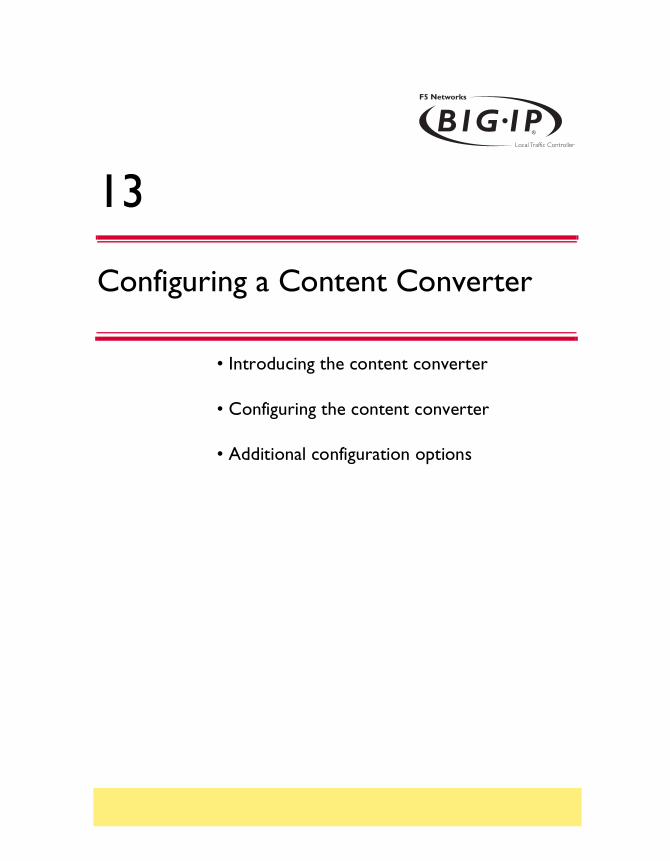
13
Configuring a Content Converter
• Introducing the content converter
• Configuring the content converter
• Additional configuration options

Configuring a Content Converter
Introducing the content converterThe content converter feature performs conversion of URLs to ARLs (Akamai Resource Locators). ARLs point to copies of URL targets that are stored on geographically nearby servers on the Akamai Freeflow NetworkTM for greater speed of access. The conversion from URL to ARL is performed whenever a client accesses a web page on a customer site containing a URL with an ARL counterpart, giving it the name on-the-fly content conversion. On-the-fly content conversion has the advantage that the HTML source does not need to be updated each time a new ARL is added.
Note
The content converter feature is usable only by customers of the Akamai Freeflow Network. In addition, the features required to configure this option are available only on the BIG-IP Controller HA and Enterprise versions.
Administrator Guide 13 - 1

Chapter 13
Figure 13.1 Content converter configured on a BIG-IP Controller system.
The content converter is set up as a proxy for the customer web site server. Figure 13.1 shows a basic content converter configuration. The proxy passes resource requests from a client to the server without modifying the content. The HTML resource sent in reply, however, is intercepted by the proxy and URLs converted to ARLs where applicable according to rules defined in a configuration file.
13 - 2 BIG-IP® Controller 4.0

Configuring a Content Converter
The client then receives an HTML page with the ARL substituted for the URL and retrieves the resource from the Akamai Freeflow Network server.
Configuring the content converterSetting up content conversion on the BIG-IP Controller includes the following steps:
• Configure the on-the-fly conversion software.
• Create a pool of web servers handling HTTP connections.
• Create a virtual server that handles connections for the web servers.
• Create the content converter gateway.
You must perform the tasks in this order. If the software is not configured first, the attempt to create a proxy will fail. The following section explains the essential tasks, and shows how you would perform each task in order to implement the example configuration.
Configuring the on-the-fly conversion software
The first task is to configure the Akamai configuration file for the on-the-fly conversion software.
1. On the BIG-IP Controller, bring up the Akamai configuration file /etc/akamai/config1.conf in an editor like vi or pico.
2. Under the heading [CpCode] you will find the text default=XXXXX. Replace the Xs with the CP code provided by your Akamai Integration Consultant. (When contacting your consultant, specify that you are using the BIG-IP on-the-fly Akamaizer based on Akamai's 1.0 source code.) Example:
default=773
Administrator Guide 13 - 3

Chapter 13
3. Under the heading [Serial Number] you will find the text staticSerialNumber=XXXXX. Replace the Xs with the static serial number provided by your Akamai Integration Consultant. Example:
staticSerialNumber=1025
Note: You need to set this value only if algorithm under [Serial Number] is set to static, as it is in the default file. If you choose to set algorithm to deterministicHash or deterministicHashBounded, the static serial number is not applicable. If you are unsure which method to select, contact your Akamai Integration Consultant.
4. Under the heading [URLMetaData] you will find the text httpGetDomains=XXXXX. Replace the X’s with domain name of the content to be converted. Example:
httpGetDomains=www.f5.com
5. Save and exit the file.
Creating the load balancing pool
Next, you need to create a load balancing pool that is required for the content converter configuration shown in Figure 13.1. You can create this pool from the Configuration utility or from the command line.
To create a pool using the Configuration utility
1. In the navigation pane, click Pools.The Pools screen opens.
2. Click the Add button.The Add Pool screen opens.
3. In the Add Pool screen, configure the attributes you want to use with the pool. For additional information about configuring a pool, click the Help button.
13 - 4 BIG-IP® Controller 4.0

Configuring a Content Converter
Configuration note
For this example, create an HTTP pool named http_pool. This pool contains the following members:10.3.0.1110.3.0.12
To define a pool from the command line
To define a pool from the command line, use the following syntax:b pool <pool_name> { member <member_definition> ... member
<member_definition> }
For example, if you want to create the pool http_pool, you would type the following command:
b pool http_pool { member 10.3.0.11:80 member 10.3.0.12:80 }
Creating the virtual server
After you create the load balancing pool, you can create a virtual server that references the pool load balancing the web servers. You can create the virtual server using the Configuration utility or from the command line.
To define a standard virtual server that references a pool using the Configuration utility
1. In the navigation pane, click Virtual Servers.
2. Click the Add button.The Add Virtual Server screen opens.
3. In the Add Virtual Server screen, fill in the attributes for the virtual server. For additional information about this screen, click the Help button.
Configuration note
To create the virtual server described in Figure 13.1, create a virtual server 192.168.200.20 on port 80 that references the pool content server pool http_pool.
Administrator Guide 13 - 5

Chapter 13
To define a standard virtual server mapping from the command line
Use the bigpipe virtual command as shown below. Also, note that you can use host names in place of IP addresses, and that you can use standard service names in place of port numbers.b virtual <virt_ip:port> use pool <pool_name>
To create the virtual server for the configuration in Figure 13.1, you would type:b virtual 192.168.200.20:80 use pool http_pool
Creating a content converter gateway using the Configuration utility
After you create the virtual server, you can create a content converter gateway. You can create the content converter gateway using the Configuration utility or from the command line.
To create a content converter gateway using the Configuration utility
1. In the navigation pane, click Proxies.The Proxies screen opens.
2. Click the Add button.The Add Proxy screen opens.
3. In the Add Proxy screen, configure the attributes you want to use with the proxy. For additional information about configuring a Proxy, click the Help button.
Configuration notes
To create the configuration shown in Figure 13.1:
• Use 192.168.200.10 for the proxy address and 192.168.200.20 for the destination address.
• Select port 80 or http for both the proxy and destination ports.
• Select Local Virtual Server as the destination target.
13 - 6 BIG-IP® Controller 4.0

Configuring a Content Converter
• Enable the proxy for Akamaization.
Creating a content converter gateway from the command line
Use the following command syntax to create a proxy:b proxy <ip>:<port> { target server <ip>:<port> akamaize enable }
For the example in Figure 13.1, you would type:
b proxy 192.168.200.10:80 { target server 192.168.200.20:80 akamaize enable }
Enabling, disabling, or deleting a content converter gateway
After you have created a content converter gateway, you can enable it, disable it, or delete it using the Configuration utility or from the command line.
Enabling or disabling a content converter gateway in the Configuration utility
1. In the navigation pane, click Proxies.The Proxies screen opens.
2. In the Proxies list, select the content converter gateway you want to enable or disable.The Proxy Properties screen opens.
3. In the Proxy Properties screen, clear the Enable box to disable the Proxy, or check the Enable box to enable the content converter gateway.
4. Click Apply.
Deleting a content converter gateway in the Configuration utility
1. In the navigation pane, click Proxies.The Proxies screen opens.
Administrator Guide 13 - 7

Chapter 13
2. In the Proxies list, click on the content converter gateway you want to delete.The Proxy Properties screen opens.
3. Click Delete.
Enabling, disabling, or deleting a content converter gateway from the command line
You can enable, disable, or delete a content converter gateway with the appropriate following syntax:b proxy <ip>:<port> enable
b proxy <ip>:<port> disable
b proxy <ip>:<port> delete
For example, if you want to enable the content converter gateway 209.100.19.22:443, type the following command:b proxy 209.100.19.22:443 enable
If you want to disable the content converter gateway 209.100.19.22:443, type the following command:b proxy 209.100.19.22:443 disable
To delete the content converter gateway 209.100.19.22:443, type the following command:b proxy 209.100.19.22:443 delete
Displaying the configuration for a content converter gateway from the command line
Use the following syntax to view the configuration for a specified content converter gateway:b proxy <ip>:<port> show
For example, if you want to view configuration information for the content converter gateway 192.168.200.10:80, type the following command:b proxy 192.168.200.10:80 show
13 - 8 BIG-IP® Controller 4.0
Configuring a Content Converter
Additional configuration optionsWhenever you configure a BIG-IP Controller, a number of options are available to you:
◆ You have the option in all configurations to configure a redundant BIG-IP Controller for fail-over. Refer to Redundant System in the BIG-IP Reference Guide, Chapter 1, Configuring the BIG-IP Controller.
◆ All configurations have health monitoring options. Refer to Health Monitors in the BIG-IP Reference Guide, Chapter 1, Configuring the BIG-IP Controller.
◆ When you create a pool, there is an option to set up persistence and a choice of load balancing methods. Refer to Pools in the BIG-IP Reference Guide, Chapter 1, Configuring the BIG-IP Controller.
PROXY +---> 192.168.200.10:80 -- Originating Address -- Enabled Unit 1 | SSL Encryption: disabled | Akamaize Content: enable +===> 10.2.10.108:80 -- Destination Address -- Server
Figure 13.2 Output from the bigpipe proxy show command
Administrator Guide 13 - 9

14
Hosting Multiple Sites
• Introducing multiple site hosting
• Configuring multiple site hosting
• Additional configuration options

Hosting Multiple Sites
Introducing multiple site hostingYou can use the BIG-IP Controller to load balance and host multiple sites. In this example, the BIG-IP Controller has a gigabit Ethernet interface tagged to handle traffic for vlanA, vlanB, and vlanC. The servers, in groups of two, host several different sites.
Figure 14.1 An example of multiple site hosting
Configuring multiple site hostingTo configure the BIG-IP Controller for this solution, you must complete the following tasks:
• Create tagged VLANs
Administrator Guide 14 - 1

Chapter 14
• Create a pool of web servers that contains the web servers that you want to load balance.
• Create a virtual server that load balances the web servers.
Creating VLAN tags
To create tagged VLANs in the Configuration utility
1. In the navigation pane, click Network.The VLAN screen opens.
2. For each VLAN:
a) Click the Add button. The Add VLAN screen opens.
b) Enter the VLAN name and tag number.
c) In the Resources box, select the internal interface (in the example, 5.1) and click tagged >>. The interface appears in the Current Interfaces box.
Configuration note
For this example, create three tagged vlans, vlanA, vlanB, and vlanC, tagged to the internal interface they connect to.
Creating tagged VLANs from the command line
You can create a tagged VLAN using the vlan tag command:b vlan <vlan_name> tag <tag_number>
You can then map an interface or interfaces to the VLAN using the tagged flag:b vlan <vlan_name> interfaces add tagged <if_list>
To create tagged VLANs vlanA, vlanB, and vlanC, type: b vlan vlanA tag 0001
b vlan vlanB tag 0002
b vlan vlanC tag 0003
To add interface 5.1 to tagged VLANs vlanA, vlanB, and vlanC, type:
14 - 2 BIG-IP® Controller 4.0

Hosting Multiple Sites
b vlan vlanA interfaces add tagged 5.1
b vlan vlanB interfaces add tagged 5.1
b vlan vlanC interfaces add tagged 5.1
Creating the server pools to load balance
After you create the network environment for the BIG-IP Controller, create three load balancing pools, one for each network.
To create a pool in the Configuration utility
1. In the navigation pane, click Pools.The Pools screen opens.
2. In the Pools screen, click the Add button to start the Add Pool wizard.
Configuration notes
For this example, create the following pools:
• server_pool1 containing the web servers 10.1.1.1:80, 10.1.1.2:80
• server_pool2 containing the web servers 10.1.2.1:80, 10.1.2.2:80
• server_pool3 containing the web servers 10.1.3.1:80 and 10.1.3.2:80.
To create a pool from the command line
To create a pool from the command line, type the following command.
b pool <pool_name> { member <server1> member <server2> ... }
In this example, you create the pool name mywebpool with the members 10.1.1.1:80, 10.1.1.2:80, 10.1.2.1:80, 10.1.2.2:80, 10.1.3.1:80 and 10.1.3.2:80:
b pool server_pool1 { member 10.1.1.1:80 member 10.1.1.2:80 }
b pool server_pool2 { member 10.1.2.1:80 member 10.1.2.2:80 }
b pool server_pool3 { member 10.1.3.1:80 member 10.1.3.2:80 }
Administrator Guide 14 - 3

Chapter 14
Creating the virtual server to load balance the web servers
After you create the web server pools that you want to load balance, create a virtual server for each pool.
To create a virtual server in the Configuration utility
1. In the navigation pane, click Virtual Servers.The Virtual Servers screen opens.
2. In the Virtual Servers screen, click the Add button to start the Add Virtual Server wizard.
Configuration notes
For this example, create the following virtual servers:
• virtual server 10.1.10.10:80 using server_pool1
• virtual server 10.1.10.11:80 using server_pool2
• virtual server 10.1.10.12:80 using server_pool3
To create a virtual server from the command line
To create the virtual server for this example from the command line, type the following command.b virtual <addr:service> use pool <pool>
In this example:b virtual 10.1.10.10:80 use pool server_pool1
b virtual 10.1.10.11:80 use pool server_pool2
b virtual 10.1.10.12:80 use pool server_pool3
Additional configuration optionsWhenever a BIG-IP Controller is configured, a number of options are available to the user:
14 - 4 BIG-IP® Controller 4.0

Hosting Multiple Sites
◆ You have the option in all configurations to configure a redundant BIG-IP Controller for fail-over. Refer to Redundant Systems in the BIG-IP Reference Guide, Chapter 1, Configuring the BIG-IP Controller.
◆ All configurations have health monitoring options. Refer to Health Monitors in the BIG-IP Reference Guide, Chapter 1, Configuring the BIG-IP Controller.
◆ When you create a pool, there is an option to set up persistence and a choice of load balancing methods. Refer to Pools in the BIG-IP Reference Guide, Chapter 1, Configuring the BIG-IP Controller.
Administrator Guide 14 - 5

15
Using Link Aggregation with Tagged VLANs
• Introducing link aggregation with tagged VLANs
• Using the two-network aggregated tagged VLAN topology
• Using the one-network aggregated tagged VLAN topology
• Additional configuration options

Using Link Aggregation with Tagged VLANs
Introducing link aggregation with tagged VLANsYou can use the BIG-IP Controller in an aggregated two-interface load balancing topology. This topology contains two interfaces (links), 4.1 and 5.1, aggregated together. There are two tagged VLANs, VLAN1 and VLAN2, passing traffic to and from the switch. A virtual server on VLAN2 load balances connections to the servers on VLAN2.
Thus, both links are on both VLANs, and inbound and outbound traffic can use either interface.
Aggregating the two links has two advantages:
• It increases the bandwidth of the individual NICs in an additive manner.
• If one link goes down, the other link can handle the traffic by itself.
This chapter describes two configurations, the two-network configuration and the single-network configuration.
Note
This configuration requires a switch with VLAN tagging and link aggregation capabilities.
Using the two-network aggregated tagged VLAN topology
Figure 15.1 shows a two-IP network topology, with one network connected to the external VLAN, and a separate network connected to the internal VLAN.
Administrator Guide 15 - 1
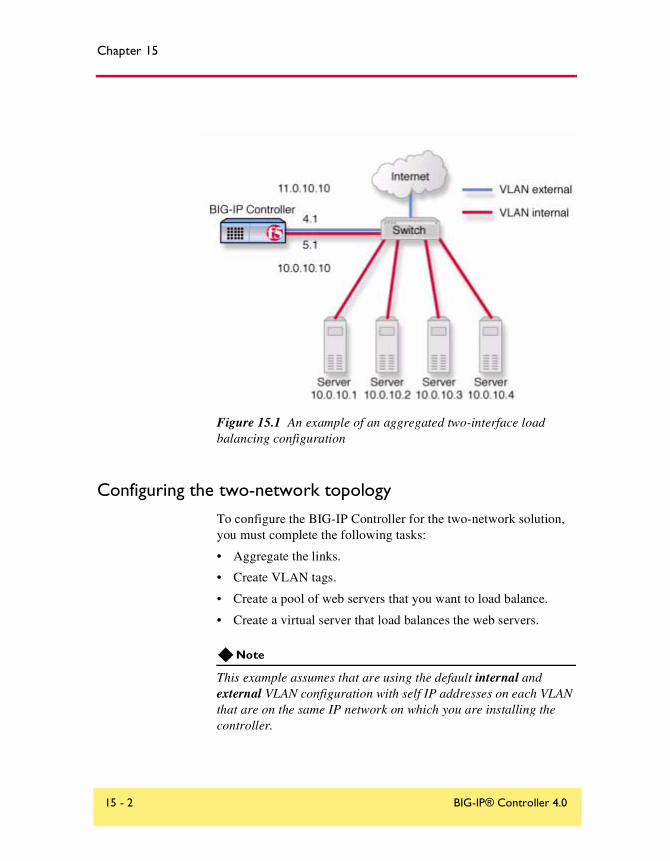
Chapter 15
Figure 15.1 An example of an aggregated two-interface load balancing configuration
Configuring the two-network topology
To configure the BIG-IP Controller for the two-network solution, you must complete the following tasks:
• Aggregate the links.
• Create VLAN tags.
• Create a pool of web servers that you want to load balance.
• Create a virtual server that load balances the web servers.
Note
This example assumes that are using the default internal and external VLAN configuration with self IP addresses on each VLAN that are on the same IP network on which you are installing the controller.
15 - 2 BIG-IP® Controller 4.0

Using Link Aggregation with Tagged VLANs
Aggregating the links
The first task for this solution is to aggregate the links.
To perform link aggregation using the Configuration utility
1. In the navigation pane, click Network.The VLANs screen opens.
2. Click on the Trunks tab.The Trunks screen opens.
3. On the Trunks screen, click the Add button. The Add Trunk screen opens.
4. Select the link that is to be the controlling link from the Available Interfaces list and click controlling >>. The interface will appear at the top of the Aggregated Interfaces list.
5. Select the remaining link from the Available Interfaces list and click aggregate >>. The interface appears in the Aggregated Interfaces list below the controlling link.
Configuration note
• For this example, aggregate interfaces 4.1 and 5.1, using 4.1 as the controlling link.
To aggregate links from the command line
You can aggregate links using the trunk flag:b trunk <controlling_if> define <if_list>
For this example, to aggregate 4.1 and 5.1, using 4.1 as the controlling link, type: b trunk 4.1 define 4.1 5.1
Administrator Guide 15 - 3

Chapter 15
Creating VLAN tags
After you aggregate the links, you can create the VLAN tags.
WARNING
You should perform this task from the console. If you attempt to change the tags from a remote workstation, you will be disconnected.
To create VLAN tags using the Configuration utility
1. In the navigation pane, click Network.The VLAN screen opens.
2. Click on the VLAN name in the list. The properties screen for the VLAN opens.
3. Specify the tagged interfaces by selecting them from the Resources list and clicking tagged >>. (It is not necessary to fill in a VLAN tag number. This is done automatically.)
Configuration note
• For this example, add the controlling interface 4.1 to the tagged list for both VLANS, external and internal.
To create VLAN tags from the command line
Using the tagged flag, you can create a tagged VLAN mapping for an interface, or interfaces, to a VLAN:b vlan <vlan_name> interfaces add tagged <if_list>
To add interfaces 4.1 and 5.1 as tagged interfaces to VLANS external and internal, type: b vlan external interfaces add tagged 4.1
b vlan internal interfaces add tagged 4.1
Tip
You only need to specify the controlling interface in this command, in this case 4.1.
15 - 4 BIG-IP® Controller 4.0

Using Link Aggregation with Tagged VLANs
Creating the pool of web servers to load balance
After you create the network environment for the BIG-IP Controller, you can create the pool of web servers you want to load balance.
To create a pool using the Configuration utility
1. In the navigation pane, click Pools.The Pools screen opens.
2. In the Pools screen, click the Add button to start the Add Pool wizard.
Configuration note
• For this example, the pool contains the web servers 10.0.10.1, 10.0.10.2, 10.0.10.31, and 10.0.0.4.
To create a pool from the command line
To create a pool from the command line, type the following command:
b pool mywebpool { member <server1> member <server2> ... }
In this example, you create the pool name mywebpool with the members 10.0.10.1, 10.0.10.2, 10.0.10.31, and 10.0.0.4:
b pool mywebpool { member 10.0.10.1 member 10.0.10.2 member 10.0.10.3 member 10.0.10.4 }
Creating the virtual server to load balance the web servers
After you create the pool of web server you want to load balance, you can create the virtual server.
To create a virtual server in the Configuration utility
1. In the navigation pane, click Virtual Servers.The Virtual Servers screen opens.
2. In the Virtual Servers screen, click the Add button to start the Add Virtual Server wizard.
Configuration note
Administrator Guide 15 - 5

Chapter 15
• For this example, the virtual server address is 10.0.10.30 and the pool is mywebpool.
To create a virtual server from the command line
To create the virtual server for this example from the command line, use the following syntax:b virtual <addr:service> use pool <pool>
To create the virtual server for this solution, you would type:b virtual 10.0.10.30:80 use pool mywebpool
Using the one-network aggregated tagged VLAN topology
Figure 15.2 shows a single IP network topology. The one-network topology is identical to the two-network topology in all respects except that in the one-network solution, the internal and external VLANs connect to members of the same IP network. This requires that the two VLANs be grouped in order to be able to exchange packets directly.
15 - 6 BIG-IP® Controller 4.0
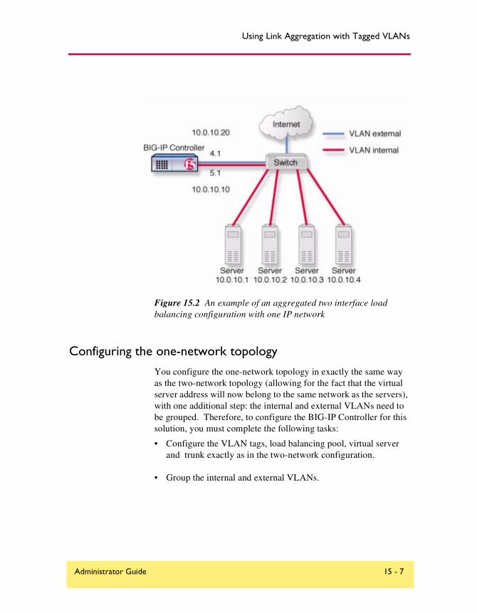
Using Link Aggregation with Tagged VLANs
Figure 15.2 An example of an aggregated two interface load balancing configuration with one IP network
Configuring the one-network topology
You configure the one-network topology in exactly the same way as the two-network topology (allowing for the fact that the virtual server address will now belong to the same network as the servers), with one additional step: the internal and external VLANs need to be grouped. Therefore, to configure the BIG-IP Controller for this solution, you must complete the following tasks:
• Configure the VLAN tags, load balancing pool, virtual server and trunk exactly as in the two-network configuration.
• Group the internal and external VLANs.
Administrator Guide 15 - 7
Chapter 15
Creating a VLAN group
Create a VLAN group that includes the internal and external VLANs. Packets received by a VLAN in the VLAN group are copied onto the other VLAN. This allows traffic to pass through the BIG-IP Controller on the same IP network.
Tip
A VLAN group name can be used anywhere a VLAN name can be used.
To create a VLAN group using the Configuration utility
1. In the navigation pane, click Network.The VLANs screen opens.
2. In the VLANs screen, click the VLAN Groups tab.The VLAN Groups screen opens.
3. In the VLAN Groups screen, click the Add button to add the VLAN group.
Configuration notes
• For this example, the VLAN group name is myvlangroup.
• Make sure the Proxy Forwarding check box is checked.
• Add the internal and external VLANs to the VLAN group.
To create a VLAN group from the command line
To create a VLAN group from the command line, type the following command:b vlangroup myvlangroup { vlans add internal external }
For this example, the VLAN group name is myvlangroup.
15 - 8 BIG-IP® Controller 4.0

Using Link Aggregation with Tagged VLANs
Creating a self IP for the VLAN group
Next, create a self IP address for the VLAN group.
To create a self IP address for a VLAN group using the Configuration utility
1. In the navigation pane, click Network.The VLANs screen opens.
2. In the Network screen, click the Self IP Addresses tab.The Self IP Addresses screen opens.
3. In the Self IP Addresses screen, click the Add button to start the Add Self IP Address wizard.
Configuration notes
• For this example, the self IP address you add for the VLAN group is 10.0.10.20.
• When you choose the VLAN to which you want to apply the self IP address, select the VLAN group you created that contains the internal and external VLANs
To create a self IP address for a VLAN group from the command line
To create a self IP address on the VLAN group, use the following command syntax:b self <addr_name> vlan <vlan_name>
To create the self IP address in this example, type the following command:b self 10.0.10.20 vlan myvlangroup
Additional configuration optionsWhenever a BIG-IP Controller is configured, a number of options are available to the user:
Administrator Guide 15 - 9
Chapter 15
◆ You have the option in all configurations to configure a redundant BIG-IP Controller for fail-over. Refer to Redundant Systems in the BIG-IP Reference Guide, Chapter 1, Configuring the BIG-IP Controller.
◆ All configurations have health monitoring options. Refer to Health Monitors in the BIG-IP Reference Guide, Chapter 1, Configuring the BIG-IP Controller.
◆ When you create a pool, there is an option to set up persistence and a choice of load balancing methods. Refer to Pools in the BIG-IP Reference Guide, Chapter 1, Configuring the BIG-IP Controller.
15 - 10 BIG-IP® Controller 4.0

16
One IP Network Topologies
• Introducing the one-IP network topology
• Setting up a one-IP network topology with one interface
• Additional configuration options

One IP Network Topologies
Introducing the one-IP network topologyAnother configuration option you can use with the BIG-IP Controller is a the one-IP network topology. This differs from the typical two-network configuration it two ways:
◆ Because there is only one physical network, this configuration does not require more than one interface on the BIG-IP Controller.
◆ Clients need to be assigned SNATs to allow them to make connections to servers on the network in a load balancing pool
The single interface configuration is shown in Figure 16.1.
Figure 16.1 An example of a single interface topology
Administrator Guide 16 - 1

Chapter 16
Setting up a one-IP network topology with one interface
To set up this configuration, you need to complete the following tasks on the BIG-IP Controller:
• Create a load balancing pool for the content servers.
• Create a virtual server for the content server pool.
• Configure a SNAT for the client.
Defining the pools for an additional Internet connection
The first task required to set up this solution is to create a pool that contains all the content servers you want to load balance.
To create pools using the Configuration utility
1. In the navigation pane, click Pools.The Pools screen opens.
2. Click the Add button.The Add Pool screen opens.
3. In the Add Pool screen, configure the pool attributes. For additional information about this screen, click the Help button.
Configuration note
For this example, you create a pool server_pool that contains the following members: <server1>, <server2>
To define pools from the command line
To define the pool server_pool for the nodes, enter:b pool server_pool { member <server1>:80 member <server2>:80 }
Replace <server1> and <server2> with IP address of the respective server.
16 - 2 BIG-IP® Controller 4.0

One IP Network Topologies
Defining the virtual server
The second task required to set up this solution is to create a virtual server that references the pool of servers that you want to load balance from the previous step.
To define the virtual server using the Configuration utility
1. In the navigation pane, click Virtual Servers.
2. Click the Add button.The Add Virtual Server screen opens.
3. Fill in the attributes for the virtual server. For additional information about this screen, click the Help button.
Configuration note
Create virtual server 192.168.13.1:80 and use pool server_pool.
To define the virtual server from the command line
Use the following command to create a virtual server for connecting to the servers.bipipe virtual 192.168.13.1:80 use pool server_pool
Configuring the client SNAT
Finally, configure the BIG-IP Controller to handle connections originating from the client. A SNAT must be defined in order to change the source address on the packet to the SNAT external address, which is located on the BIG-IP Controller. If a SNAT were not defined, the server would return the packets directly to the client without giving the BIG-IP Controller the opportunity to translate the source address from the server address back to the virtual server. The client would not recognize the packet if the source address of the returning packet is the IP address of the real server because the client sent its packets to the IP address of the virtual server.
Configure the SNAT using the bigpipe snat command:
Administrator Guide 16 - 3

Chapter 16
b snat map client1 to 192.168.13.99
Replace client1 with the actual name of the client in your configuration.
Additional configuration optionsWhenever a BIG-IP Controller is configured, a number of options are available to the user:
◆ You have the option in all configurations to configure a redundant BIG-IP Controller for fail-over. Refer to Redundant Systems in the BIG-IP Reference Guide, Chapter 1, Configuring the BIG-IP Controller.
◆ All configurations have health monitoring options. Refer to Health Monitors in the BIG-IP Reference Guide, Chapter 1, Configuring the BIG-IP Controller.
◆ When you create a pool, there is an option to set up persistence and a choice of load balancing methods. Refer to Pools in the BIG-IP Reference Guide, Chapter 1, Configuring the BIG-IP Controller.
16 - 4 BIG-IP® Controller 4.0

17
nPath routing
• Introducing nPath routing
• Additional configuration options

nPath routing
Introducing nPath routingThe nPath routing configuration allows you to route outgoing server traffic around the BIG-IP Controller directly to an outbound router in a single interface configuration. (For more information about the single interface configuration, refer to Chapter 16, One IP Network Topologies.) This method of traffic management increases outbound throughput because packets do not need to be transmitted to the BIG-IP Controller for translation and forwarding to the next hop. Figure 17.1 shows an nPath configuration.
Figure 17.1 An example nPath configuration
Note
This configuration does not support late binding features such as SSL persistence, cookie persistence, and content switching.
Administrator Guide 17 - 1

Chapter 17
In bypassing the BIG-IP Controller on the return path, nPath departs significantly from a typical load-balancing configuration. In a typical load-balancing configuration, the destination address of the incoming packet is translated from that of the virtual server to that of the node being load balanced to, which then becomes the source address of the returning packet. A default route set to the BIG-IP Controller then sees to it that packets returning to the originating client return through the controller, which translates the source address back to that of the virtual server.
The nPath routing configuration differs from this configuration in the following ways:
◆ The default route must be set to the router inside address, not the controller self-address (10.1.1.1 in Figure 17.1). This causes the return packet to bypass the BIG-IP Controller.
◆ Because the BIG-IP Controller is no longer in the return loop, a translated destination address will not be translated back to the virtual server address. Consequently, it is necessary to turn off address translation on the virtual server. This way the source address on the return packet will match the destination address of the outbound packet and be recognized by the originating client.
◆ Because address translation has been turned off, it is turned off in both directions, meaning that the incoming packet will arrive at the server it is load balanced to with the untranslated virtual server address (11.1.1.1 in Figure 17.1), not the address of the server. For the server to respond to that address, that address must be placed on the loopback interface of the server.
◆ Because the address placed on the loopback interface must be on a different IP network, the virtual server address must also be on a different network than that of the BIG-IP Controller self address. (Thus the virtual server address 11.1.1.1.) This means that the incoming packet with the virtual server address as its destination must have a route to that address.
With nPath routing, you will also need to set an appropriate idle connection time-out value so that valid connections are not disconnected, and closed connections are cleaned up in a reasonable time.
17 - 2 BIG-IP® Controller 4.0
nPath routing
You need to complete the following tasks to configure the BIG-IP Controller to use nPath routing.
• Define a server pool.
• Define a virtual server with address and port translation off.
• Configure the virtual server address on the server loopback interface.
• Set a route on your routers to the virtual server with the BIG-IP Controller as the gateway.
• Set the default route on your servers to the router.
• Set idle connection timeouts.
Defining a server pool for nPATH routing
The first task you need to complete for nPATH routing is to create a server pool.
To create pools using the Configuration utility:
1. In the navigation pane, click Pools.The Pools screen opens.
2. Click the Add button.The Add Pool screen opens.
3. In the Add Pool screen, configure the attributes you want to use with the pool. For additional information about configuring a pool, click the Help button.
Configuration note
• For this example, you would create an HTTP pool named http_pool containing the following members:10.1.1.1110.1.1.12
To create a pool from the command line
To define a pool from the command line, use the following syntax:
Administrator Guide 17 - 3

Chapter 17
b pool <pool_name> { member <member_definition> ... member <member_definition>}
To create the pool http_pool, type the following command:
b pool http_pool { member 10.1.1.11 member 10.1.1.12 }
Defining a virtual server with address translation disabled
After you create a pool server pool, you need to create a virtual server with address translation off.
To define a standard virtual server using the Configuration utility
1. In the navigation pane, click Virtual Servers.
2. Click the Add button.The Add Virtual Server screen opens.
3. The Add Virtual Server screen, configure the virtual server attributes. For additional information about configuring a pool, click the Help button.
Configuration notes
• For this example, you would create a virtual server 11.11.11.1 that references the HTTP pool named http_pool.
• For this virtual server, clear the Address Translation Enabled check box to disable address translation.
To define a virtual server mapping from the command line
To define a virtual server at the command line, use the following syntax.b virtual <virtual_ip>:<port> use pool <pool>
For this example:b virtual 11.1.1.1:80 use pool http_pool
17 - 4 BIG-IP® Controller 4.0

nPath routing
After you create the virtual server, you must turn off address and port translation using the following syntax:b virtual <virtual_ip>:<port> translate addr disable
b virtual <virtual_ip>:<port> translate port disable
For example, use the following command to turn off address translation for the virtual server 11.1.1.1:80.b virtual 11.1.1.1:80 translate addr disable
b virtual 11.1.1.1:80 translate port disable
Configuring the virtual server on the content server loopback interface
The IP address of the virtual server (11.1.1.1 in Figure 17.1) must be placed on the loopback interface of each server. Most UNIX variants have a loopback interface named lo0. Microsoft Windows has an MS Loopback interface in its list of network adaptors. Consult your server operating system documentation for information about configuring an IP address on the loopback interface. The ideal loopback interface for the nPath configuration does not participate in the ARP protocol, because that would cause packets to be routed incorrectly.
Setting the route for inbound trafficFor inbound traffic, you must define a route through the BIG-IP Controller self IP address to the virtual server. In the example, this route is 11.1.1.1, with the self address 10.1.1.1 as the gateway.
For information about how to define this route, please refer to the documentation provided with your router.
Setting the return route
For the return traffic, you must define a route from the servers directly to the router inside address. In this example, this route is 10.1.1.1.
Administrator Guide 17 - 5
Chapter 17
For information about how to define this route, please refer to the documentation provided with your servers.
Setting the idle connection time-out
With nPath routing, the BIG-IP Controller cannot track the normal FIN/ACK sequences made by connections. Normally, the BIG-IP Controller shuts down closed connections based on this sequence. With nPath routing, the idle connection time-out must be configured to clean up closed connections. You need to set an appropriate idle connection time-out value so that valid connections are not disconnected, and closed connections are cleaned up in a reasonable time.
To set the idle connection time-out using the Configuration utility
1. In the navigation pane, click Virtual Servers.The Virtual Servers screen opens.
2. Click the Virtual Ports tab.The Virtual Ports screen opens.
3. In the Virtual Port box, click the port.The Virtual Port Properties screen opens.
4. In the Idle connection timeout TCP (seconds) box, type a time-out value for TCP connections. The recommended time-out setting is 10 seconds.
5. In the Idle connection timeout UDP (seconds) box, type a time-out value for TCP connections. The recommended time-out setting is 10 seconds.
6. Click Apply.
To set the idle connection time-out from the command line
To set the idle connection time-out at the command line, use the following syntax:b service <port> timeout tcp <seconds>
17 - 6 BIG-IP® Controller 4.0

nPath routing
b service <port> timeout udp <seconds>
The <seconds> value is the number of seconds a connection is allowed to remain idle before it is terminated. The <port> value is the port on the wildcard virtual server for which you are configuring out of path routing. The recommended value for the TCP and UDP connection timeouts is 10 seconds.
Additional configuration optionsWhenever you configure a BIG-IP Controller, a number of options are available to you:
◆ You have the option in all configurations to configure a redundant BIG-IP Controller for fail-over. Refer to Redundant Systems in the BIG-IP Reference Guide, Chapter 1, Configuring the BIG-IP Controller.
◆ All configurations have health monitoring options. Refer to Health Monitors in the BIG-IP Reference Guide, Chapter 1, Configuring the BIG-IP Controller.
◆ When you create a pool, there is an option to set up persistence and a choice of load balancing methods. Refer to Pools in the BIG-IP Reference Guide, Chapter 1, Configuring the BIG-IP Controller.
Administrator Guide 17 - 7
18
Monitoring and Administration
• Monitoring and administration utilities
• Using the bigpipe utility as a monitoring tool
• Using the Configuration utility for administration and monitoring
• Working with the BIG/top utility
• Working with the Syslog utility
• Removing and returning items to service
• Viewing system statistics and log files
• Printing the connection table
• Changing passwords
• Working with the BIG/db database
• Working with the BIG/stat utility

Monitoring and Administration
Monitoring and administration utilitiesThe BIG-IP platform provides several utilities for monitoring and administration of the BIG-IP Controller. You can monitor system statistics, as well as statistics specific to virtual servers and nodes, such as the number of current connections, and the number of packets processed since the last reboot.
The BIG-IP platform provides the following monitoring and configuration and administration utilities:
◆ bigpipeIf you type certain bigpipe commands, such as bigpipe virtual or bigpipe node, and use the show keyword in the command, the command displays statistical information about the elements that you configure using that command. You can also use bigpipe commands to selectively reset any statistic collected by the BIG-IP Controller.
◆ The Configuration utilityYou can use the Configuration utility to configure any feature on the BIG-IP Controller. You can reset any statistic, or all statistics, for virtual servers, nodes, NATs, and SNATs in the Configuration utility.
◆ BIG/statThis utility is provided specifically for statistical monitoring of virtual servers, nodes, NATs, SNATs, and services. One benefit of using BIG/stat is that it allows you to customize the display of statistical information.
◆ BIG/topBIG/top provides statistical monitoring. You can set a refresh interval, and you can specify a sort order.
◆ SyslogSyslog is the standard UNIX system logging utility, which monitors critical system events, as well as configuration changes made on the BIG-IP Controller.
◆ BIG/dbBIG/db is a database that contains various configuration information for the BIG-IP Controller.
Administrator Guide 18 - 1

Chapter 18
Using the bigpipe utility as a monitoring toolUsing the bigpipe utility, you can view information about the BIG-IP Controller itself, as well as elements such as virtual servers, virtual addresses, virtual ports, nodes, and node addresses. Typically, the bigpipe utility provides the following statistics:
• Current number of connections
• Maximum number of concurrent connections
• Total number of connections since the last system reboot
• Total number of bits (inbound, outbound, total)
• Total number of packets (inbound, outbound, total)
Monitoring the BIG-IP Controller
The bigpipe summary command displays performance statistics for the BIG-IP Controller itself. This display summary includes current usage statistics, such as the amount of time a BIG-IP Controller has been running since the last reboot. To display a summary of the performance statistics for the controller, type the following command:b summary
18 - 2 BIG-IP® Controller 4.0

Monitoring and Administration
The performance statistics display in the format shown in Figure 18.1 (the output has been truncated for this example).
BIG-IP total uptime = 1 (day) 4 (hr) 40 (min) 8 (sec)BIG-IP total uptime (secs) = 103208BIG-IP total # connections = 0BIG-IP total # pkts = 0BIG-IP total # bits = 0BIG-IP total # pkts(inbound) = 0BIG-IP total # bits(inbound) = 0BIG-IP total # pkts(outbound) = 0BIG-IP total # bits(outbound) = 0BIG-IP error no nodes available = 0BIG-IP tcp port deny = 0BIG-IP udp port deny = 0BIG-IP virtual tcp port deny = 0BIG-IP virtual udp port deny = 0BIG-IP max connections deny = 0BIG-IP virtual duplicate syn ssl = 0BIG-IP virtual duplicate syn wrong dest = 0BIG-IP virtual duplicate syn node down = 0BIG-IP virtual maint mode deny = 0BIG-IP virtual addr max connections deny = 0BIG-IP virtual path max connections deny = 0BIG-IP virtual non syn = 0BIG-IP error not in out table = 0BIG-IP error not in in table = 0BIG-IP error virtual fragment no port = 0BIG-IP error virtual fragment no conn = 0BIG-IP error standby shared drop = 0BIG-IP dropped inbound = 0BIG-IP dropped outbound = 0BIG-IP reaped = 0BIG-IP ssl reaped = 0BIG-IP persist reaped = 0BIG-IP udp reaped = 0BIG-IP malloc errors = 0BIG-IP bad type = 0BIG-IP mem pool total 96636758 mem pool used 95552 mem percent used 0.10
Figure 18.1 The bigpipe summary display screen
Administrator Guide 18 - 3

Chapter 18
Table 18.1 contains descriptions of each individual statistic included in the summary display screen.
Statistic Description
total uptime Total time elapsed since the BIG-IP Controller was last booted.
total uptime (secs) Total uptime displayed in seconds.
total # connections Total number of connections handled.
total # pkts Total number of packets handled.
total # bits Total number of bits handled.
total # pkts (inbound) Total number of incoming packets handled.
total # bits (inbound) Total number of incoming bits handled.
total # pkts (outbound) Total number of outgoing packets handled.
total # bits (outbound) Total number of outgoing bits handled.
error no nodes available The number of times the BIG-IP Controller tried to make a connection to a node, but no nodes are available.
tcp port deny The number of times a client attempted to connect to an unauthorized TCP port on the BIG-IP Controller (unauthorized port and source IP are logged in the syslog).
udp port deny The number of times a client attempted to connect to an unauthorized UDP port on the BIG-IP Controller (unauthorized port and source IP are logged in the syslog).
virtual tcp port deny The number of times a client attempted to connect to an unauthorized TCP port on a virtual address (unauthorized port and source IP are logged in the syslog).
virtual udp port deny The number of times a client attempted to connect to an unauthorized UDP port on a virtual address (unauthorized port and source IP are logged in the syslog).
Table 18.1 bigpipe monitoring statistics
18 - 4 BIG-IP® Controller 4.0

Monitoring and Administration
max connections deny The total number of connections denied because the maximum number of connections allowed was exceeded.
virtual duplicate syn ssl The number of duplicate connection attempts to existing SSL connections from the same client.
virtual duplicate syn wrong dest
The number of duplicate connection attempts from the same client (address and port combination) to a different virtual server.
virtual duplicate syn node down
The number of duplicate connection attempts to a server that is down when a connection to the server was made previously.
virtual maint mode deny The number of times a connection to a virtual server was denied while the BIG-IP Controller is in maintenance mode.
virtual addr max connections deny
The number of virtual address connections dropped because the maximum number of connections was exceeded.
virtual path max connections deny
The number of virtual path connections dropped because the maximum number of connections was exceeded.
virtual non syn The number of packets received which are not connection requests, and are destined to a virtual address, but not a valid virtual server (port).
error virtual fragment no port The number of IP fragments for which there is no port.
error virtual fragment no conn
The number of IP fragments for which there is no connection.
error standby shared drop The number of packets destined to the shared IP address in a redundant system that are received and ignored by the standby system.
dropped inbound The total number of inbound packets dropped by the BIG-IP Controller.
dropped outbound The total number of outbound packets dropped by the BIG-IP Controller.
Statistic Description
Table 18.1 bigpipe monitoring statistics
Administrator Guide 18 - 5

Chapter 18
Resetting statistics on the BIG-IP Controller
The bigpipe commands allow you to selectively reset any statistic on the BIG-IP Controller. The statistics you can reset selectively include:
• Virtual address
• Virtual server
• Node address
• Node server
• Virtual port
• Network address translations (NATs)
• Global statistics
reaped The total number of connections that timed-out, and are deleted by the BIG-IP Controller.
ssl reaped The total number of SSL session ID records that timed-out, and are closed by the BIG-IP Controller.
persist reaped The total number of persistence records that timed-out, and are closed by the BIG-IP Controller.
udp reaped The total number of UDP connections that timed-out, and are closed by the BIG-IP Controller.
malloc errors The number of times a connection could not be created because the system is low on memory.
mem pool total The total amount of memory available in all combined memory pools.
mem pool used The total amount of memory, in all combined memory pools, in use by the BIG-IP Controller.
mem percent used The total percentage of memory in use by all combined memory pools.
Statistic Description
Table 18.1 bigpipe monitoring statistics
18 - 6 BIG-IP® Controller 4.0

Monitoring and Administration
When you reset one of these items, the packets in, packets out, bytes in, and bytes out counters of the target item are reset to zero. The maximum connection count counter is also reset. The current connections counter is not reset, and the total connections counter is set equal to the number of current connections.
Note
The statistics are reset for the specified items only. Statistics for dependent items, such as node servers for a given virtual address, are not modified by these commands. The only exception is the global statistics reset option which resets traffic statistics for all items. After an item-level reset, statistics for all other dependent items do not add up.
You can create an audit trail for reset events by setting an optional system control variable. You can set this variable to generate a syslog log entry. To set this variable, type the following command:b internal set verbose_log_level=4
To reset statistics for virtual servers and virtual addresses
Use the following syntax to reset statistics for the virtual address specified by the IP address <virtual ip>.b virtual <virtual_ip> stats reset
For example, if you want to reset statistics for the virtual address 172.20.1.100, type the following command:b virtual 172.20.1.100 stats reset
If you want to reset statistics for a list of virtual addresses, type the command with a list of addresses separated by spaces:
b virtual 172.20.1.100 172.20.1.101 172.20.1.102 stats reset
If you want to reset statistics for all virtual servers, use the following command:b virtual stats reset
Use the following syntax to reset statistics for the virtual server IP:port combination <virtual_ip>:<port>.b virtual <virtual_ip>:<port> stats reset
Administrator Guide 18 - 7

Chapter 18
For example, if you want to reset statistics for the virtual address/port combination 172.20.1.100:80, type the following command:b virtual 172.20.1.100:80 stats reset
If you want to reset statistics for a list of virtual address/port combinations, type the command with the list of addresses separated by spaces:
b virtual 172.20.1.100:80 172.20.1.100:23 172.20.1.101:80 stats reset
To reset statistics for node servers and node addresses
Use the following syntax to reset statistics for all node addresses and node servers.b node stats reset
You can reset statistics for the node address specified by the IP address <node_ip>.b node <node_ip> stats reset
For example, to reset the statistics for the node address 10.1.1.1, use the following syntax:b node 10.1.1.1 stats reset
If you want to reset statistics for a list of node addresses, type the command with the list of addresses separated by spaces:b node 10.1.1.1 10.1.1.2 10.1.1.3 stats reset
Use the following syntax to reset statistics for the node server specified by the IP:port combination <node_ip>:<port>.b node <node_ip>:<port> stats reset
For example, to reset the statistics for the node server 10.1.1.1:80, use the following syntax:b node 10.1.1.1:80 stats reset
If you want to reset statistics for a list of node server addresses, type the command with the list of addresses separated by spaces:b node 10.1.1.1:80 10.1.1.2:23 stats reset
To reset statistics for virtual ports
Use the following syntax to reset statistics for all virtual ports:
18 - 8 BIG-IP® Controller 4.0

Monitoring and Administration
b service stats reset
Use the following syntax to reset statistics for the virtual port <port>. You can specify a list of virtual ports separated by spaces.b service <port> stats reset
For example, to reset the statistics for the virtual port 80, use the following command:b service 80 stats reset
To reset the statistics for a list of virtual ports, use the following syntax:b service 23 80 443 stats reset
Resetting statistics for network address translations (NATs)
Use the following syntax to reset statistics for all NATs:b nat stats reset
Use the following syntax to reset statistics for the NAT for the IP address <orig_ip>.b nat <orig_ip> stats reset
For example, to reset the statistics for the NAT 172.20.3.101, use the following command:b nat 172.20.3.101 stats reset
To reset the statistics for a list of origin IPs, use the following command where addresses are separated by spaces:b nat 172.20.3.101 172.20.3.102 stats reset
To reset statistics for secure network address translations (SNATs)
Use the following syntax to reset statistics for all SNATs:b snat stats reset
Use the following syntax to reset statistics for the SNAT for IP address <snat_ip>.b snat <snat_ip> stats reset
Administrator Guide 18 - 9
Chapter 18
For example, to reset the statistics for the SNAT 172.20.3.101, use the following command:b snat 172.20.3.101 stats reset
To reset the statistics for a list of SNAT origin addresses, use the following command where addresses are separated by spaces:b snat 172.20.3.101 172.20.3.102 stats reset
To reset global statistics
Use the following command to reset all statistics for all items.b global stats reset
To reset any statistic in the Configuration utility
A Reset button is located in each of the following tables in the Configuration utility:
• Virtual address
• Virtual server
• Node address
• Node server
• Virtual port
• Network address translations (NATs)
• Global statistics
To reset a statistic for a particular item, click the Reset button next to the item in one of these tables.
Monitoring virtual servers, virtual addresses and services
You can use different variations of the bigpipe virtual command, as well as the bigpipe port command, to monitor information about virtual servers, virtual addresses, and services managed by the BIG-IP Controller.
18 - 10 BIG-IP® Controller 4.0

Monitoring and Administration
Displaying information about virtual servers and virtual addresses
The bigpipe virtual command displays the status of virtual servers (up, down, unchecked, or disabled), the current number of connections to each virtual server, and the status of the member nodes that are included in each virtual server mapping. The status for individual member nodes includes whether the node is up, down, unchecked, or disabled, and also includes the cumulative count of packets and bits received and sent by the node on behalf of the virtual server. The BIG-IP Controller displays the statistics as shown in Figure 18.2.
virtual +------> 11.11.11.50 UNIT 1 | (cur, max, limit, tot) = (0, 8, 0, 370) | (pckts,bits) in = (10704, 8744872), out = (21480, 230874016) +---+--> PORT http UP | (cur, max, limit, tot) = (0, 8, 0, 370) | (pckts,bits) in = (10704, 8744872), out = (21480, 230874016) POOL appgen_11.11.11.50.80 MEMBER 11.12.11.100:http UP (cur, max, limit, tot) = (0, 8, 0, 370) (pckts,bits) in = (10704, 8744872), out = (21480, 230874016)
virtual +------> 11.11.11.101 UNIT 1 | (cur, max, limit, tot) = (0, 2, 0, 4) | (pckts,bits) in = (4532, 2090768), out = (6824, 82113984) +---+--> PORT http UP | (cur, max, limit, tot) = (0, 2, 0, 4) | (pckts,bits) in = (4532, 2090768), out = (6824, 82113984) POOL my_website_pool MEMBER 11.12.11.100:http UP (cur, max, limit, tot) = (0, 2, 0, 4) (pckts,bits) in = (4532, 2090768), out = (6824, 82113984)
Figure 18.2 Virtual server statistics
Administrator Guide 18 - 11

Chapter 18
If you want to view statistical information about one or more specific virtual servers, simply include the virtual servers in the bigpipe virtual show command as shown below:
b virtual <virt addr>:<port>... <virt addr>:<port> show
If you want to view statistical information about traffic going to one or more virtual addresses, specify only the virtual address information in the command:
b virtual <virt addr>... <virt addr> show
Displaying information about services
The bigpipe port show command allows you to display information about specific virtual ports managed by the BIG-IP Controller. You can use the command to display information about all virtual services, or you can specify one or more particular virtual services.
To view information about all virtual services, use the following syntax:b service show
To view statistical information about one or more specific virtual services, simply include the service names or port numbers as shown below:b service <port>... <port> show
Monitoring nodes and node addresses
The bigpipe node command displays the status of all nodes configured on the BIG-IP Controller. The information includes whether the specified node is up, down, disabled, or unchecked,
18 - 12 BIG-IP® Controller 4.0

Monitoring and Administration
and the number of cumulative packets and bits sent and received by each node on behalf of all virtual servers. The BIG-IP Controller displays the statistical information as shown in Figure 18.3.
If you want to view statistical information about one or more specific nodes, simply include the nodes in the bigpipe node show command as shown below:
b node <node addr>:<port>... <node addr>:<port> show
If you want to view statistical information about traffic going to one or more node addresses, specify only the node address information in the command:b node <node addr>... <node addr> show
Monitoring NATs
The bigpipe nat show command displays the status of the NATs configured on the BIG-IP Controller. The information includes the number of cumulative packets and bits sent and received by each NAT. Use the following command to display the status of all NATs included in the configuration:b nat show
Use the following syntax to display the status of one or more selected NATs:b nat <node addr> [...<node addr>] show
NODE 11.12.11.100 UP | (cur, max, limit, tot) = (0, 8, 0, 374)| (pckts,bits) in = (15236, 10835640), out = (28304, 312988000)+- PORT http UP (cur, max, limit, tot) = (0, 8, 0, 374) (pckts,bits) in = (15236, 10835640), out = (28304, 312988000)
Figure 18.3 Node statistics screen
Administrator Guide 18 - 13
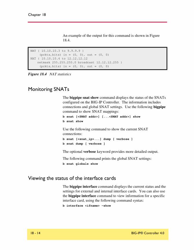
Chapter 18
An example of the output for this command is shown in Figure 18.4.
Monitoring SNATs
The bigpipe snat show command displays the status of the SNATs configured on the BIG-IP Controller. The information includes connections and global SNAT settings. Use the following bigpipe command to show SNAT mappings:b snat [<SNAT addr>] [...<SNAT addr>] show
b snat show
Use the following command to show the current SNAT connections:b snat [<snat_ip>...] dump [ verbose ]
b snat dump [ verbose ]
The optional verbose keyword provides more detailed output.
The following command prints the global SNAT settings:b snat globals show
Viewing the status of the interface cards
The bigpipe interface command displays the current status and the settings for external and internal interface cards. You can also use the bigpipe interface command to view information for a specific interface card, using the following command syntax:b interface <ifname> -show
NAT { 10.10.10.3 to 9.9.9.9 } (pckts,bits) in = (0, 0), out = (0, 0)
NAT { 10.10.10.4 to 12.12.12.12 netmask 255.255.255.0 broadcast 12.12.12.255 } (pckts,bits) in = (0, 0), out = (0, 0)
Figure 18.4 NAT statistics
18 - 14 BIG-IP® Controller 4.0

Monitoring and Administration
Using the Configuration utility for administration and monitoring
The Configuration utility System Admin screen may be used to add users, customize the GUI, configure SNMP, and save and restore a current configuration.
You can use the Configuration utility to allow access to the SNMP agent and to set SNMP properties. For more information on configuring SNMP, refer to Chapter 19, Configuring SNMP.
Adding a user
To add a user to the BIG-IP Controller in the Configuration utility
1. In the navigation pane, click System Admin.The System Admin tabs appear.
2. Click the User Administration tab.The Add User screen opens. This screen contains a list of current users.
3. In the Add User screen, type the User ID, password, and access level for the user.For more information on the Add User screen, click the Help button.
Customizing the Configuration utility
To customize the Configuration utility using the Configuration utility
1. In the navigation pane, click System Admin.The User Administration screen opens.
2. Click the Web UI Administration tab.The WEB UI Administration screen opens.
Administrator Guide 18 - 15

Chapter 18
3. Select the options you want to configure.For more information about the options available on this screen, click the Help button.
Configuring SNMP
For information on configuring SNMP, refer to Chapter 19, Configuring SNMP.
Working with the BIG/top utilityBIG/top™ is a real-time statistics display utility. The display shows the date and time of the latest reboot and lists activity in bits, bytes, or packets. Similar to BIG/stat, the BIG/top utility accepts options which allow you to customize the display of information. For example, you can set the interval at which the data is refreshed, and you can specify a sort order. The BIG/top displays the statistics as shown in the following figure, Figure 18.5.
| bits since | bits in prior | current | Nov 28 18:47:50 | 3 seconds | timeBIG-IP ACTIVE |---In----Out---Conn-|---In----Out---Conn-| 00:31:59227.19.162.82 1.1G 29.6G 145 1.6K 0 0
virtual ip:port |---In----Out---Conn-|---In----Out---Conn-|-Nodes Up--217.87.185.5:80 1.0G 27.4G 139.6K 1.6K 0 0 2217.87.185.5:20 47.5M 2.1G 3.1K 0 0 0 2217.87.185.5:20 10.2M 11.5M 2.6K 0 0 0 2
NODE ip:port |---In----Out---Conn-|---In----Out---Conn-|--State----129.186.40.17:80 960.6M 27.4G 69.8K 672 0 0 UP129.186.40.17:20 47.4M 2.1G 3.1K 0 0 0 UP129.186.40.18:80 105.3M 189.0K 69.8K 1.0K 0 0 UP129.186.40.17.21 9.4M 11.1M 1.3K 0 0 0 UP129.186.40.18:21 700.8K 414.7K 1.3K 0 0 0 UP129.186.40.18:20 352 320 1 0 0 0 UP
Figure 18.5 The BIG/top screen display
18 - 16 BIG-IP® Controller 4.0

Monitoring and Administration
Using BIG/top command options
The bigtop command uses the syntax below, and it supports the options outlined in Table 18.2:bigtop [options...]
Using runtime commands in BIG/top
Unless you specified the -once option, the BIG/top utility continually updates the display at the rate indicated by the -delay option, and you can also use the following runtime options at any time:
• The u option cycles through the display modes: bits, bytes, and packets.
Option Description
-bytes Displays counts in bytes (the default is bits).
-conn Sorts by connection count (the default is to sort by byte count).
-delay <value> Sets the interval at which data is refreshed (the default is four seconds).
-delta Sorts by count since last sample (the default is to sort by total count).
-help Displays BIG/top help.
-nodes <value> Sets the number of nodes to print (the default is to print all nodes).
-nosort Disables sorting.
-once Prints the information once and exits.
-pkts Displays the counts in packets (the default is bits).
-scroll Disables full-screen mode.
-virtuals <value> Sets the number of virtual servers to print (the default is to print all virtual servers).
Table 18.2 BIG/top command options
Administrator Guide 18 - 17

Chapter 18
• The q option quits the BIG/top utility.
Working with the Syslog utilityThe BIG-IP Controller supports logging via the Syslog utility. The logs are generated automatically, and saved in user-specified files. These logs contain all changes made to the BIG-IP Controller configuration, such as those made with the bigpipe virtual command, or other bigpipe commands, as well as all critical events that occur in the system.
Note
You can configure the Syslog utility to send email or activate pager notification based on the priority of the logged event.
The Syslog log files track system events based on information defined in the /etc/syslog.conf file. You can view the log files in a standard text editor, or with the less file page utility.
Sample log messages
Table 18.3 shows sample log messages to give you an idea of how the Syslog utility tracks events that are specific to the BIG-IP Controller.
Sample message Description
bigd: allowing connections on port 20 A user specifically allowed connections on virtual port 20.
bigd: node 192.168.1.1 detected up The 192.168.1.1 node address was successfully pinged by the BIG-IP Controller.
Table 18.3 Sample Syslog messages
18 - 18 BIG-IP® Controller 4.0
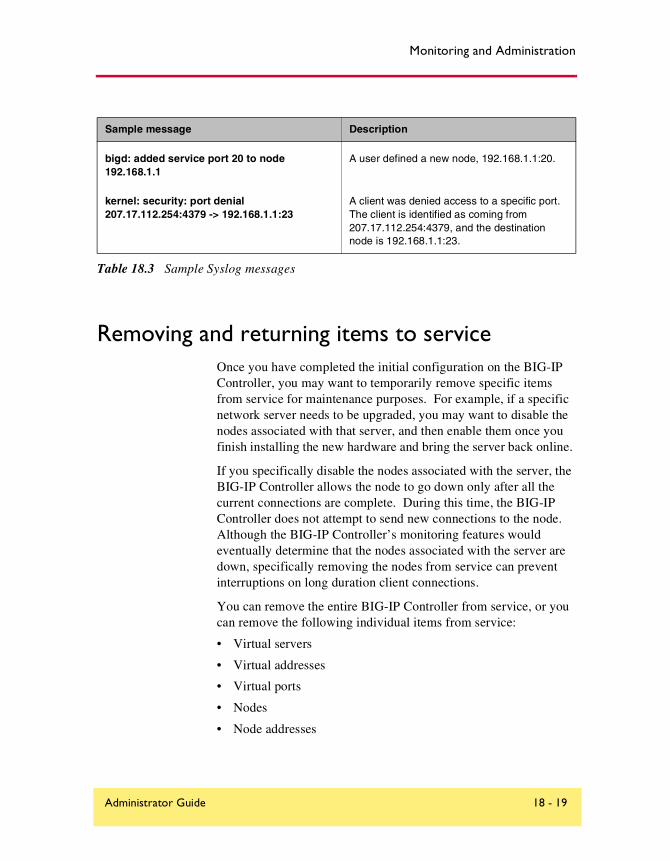
Monitoring and Administration
Removing and returning items to serviceOnce you have completed the initial configuration on the BIG-IP Controller, you may want to temporarily remove specific items from service for maintenance purposes. For example, if a specific network server needs to be upgraded, you may want to disable the nodes associated with that server, and then enable them once you finish installing the new hardware and bring the server back online.
If you specifically disable the nodes associated with the server, the BIG-IP Controller allows the node to go down only after all the current connections are complete. During this time, the BIG-IP Controller does not attempt to send new connections to the node. Although the BIG-IP Controller’s monitoring features would eventually determine that the nodes associated with the server are down, specifically removing the nodes from service can prevent interruptions on long duration client connections.
You can remove the entire BIG-IP Controller from service, or you can remove the following individual items from service:
• Virtual servers
• Virtual addresses
• Virtual ports
• Nodes
• Node addresses
bigd: added service port 20 to node 192.168.1.1
A user defined a new node, 192.168.1.1:20.
kernel: security: port denial 207.17.112.254:4379 -> 192.168.1.1:23
A client was denied access to a specific port. The client is identified as coming from 207.17.112.254:4379, and the destination node is 192.168.1.1:23.
Sample message Description
Table 18.3 Sample Syslog messages
Administrator Guide 18 - 19

Chapter 18
Removing the BIG-IP Controller from service
The BIG-IP platform offers a Maintenance mode, which allows you to remove the BIG-IP Controller from network service. This is useful if you want to perform hardware maintenance, or make extensive configuration changes. When you activate Maintenance mode, the BIG-IP Controller no longer accepts connections to the virtual servers it manages. However, the existing connections are allowed to finish processing so that current clients are not interrupted.
The bigpipe maint command toggles the BIG-IP Controller into or out of Maintenance mode. Use the following command to put the BIG-IP Controller in maintenance mode:b maint
If the BIG-IP Controller runs in Maintenance mode for less than 20 minutes and you return the machine to the normal service, the BIG-IP Controller quickly begins accepting connections. However, if the BIG-IP Controller runs in Maintenance mode for more than 20 minutes, returning the Controller to service involves updating all network ARP caches. This process can take a few seconds, but you can speed the process up by reloading the /config/bigip.conf file using the following command:b -f /config/bigip.conf
To activate maintenance mode using the Configuration utility
1. In the navigation pane, click System. The Network Map screen opens.
2. Click the Properties tab.The Properties screen opens.
3. Place a check in the Maintenance Mode box.
4. Click the Apply button.
18 - 20 BIG-IP® Controller 4.0

Monitoring and Administration
Removing individual virtual servers, virtual addresses, and ports from service
The BIG-IP Controller also supports taking only selected virtual servers, addresses, or ports out of service, rather than removing the BIG-IP Controller itself from service. Each bigpipe command that defines virtual servers and their components supports enable and disable keywords, which allow you to remove or return the elements from service.
When you remove a virtual address or a virtual port from service, it affects all virtual servers associated with the virtual address or virtual port. Similarly, if you remove a node address from service, it affects all nodes associated with the node address.
Enabling and disabling virtual servers and virtual addresses
The bigpipe virtual command allows you to enable or disable individual virtual servers, as well as virtual addresses. To enable or disable a virtual server, type the appropriate command:b virtual <virtual addr>:<virtual port> enable
b virtual <virtual addr>:<virtual port> disable
To enable or disable a virtual address, type the appropriate command:b virtual <virtual addr> enable
b virtual <virtual addr> disable
Enabling and disabling virtual ports
The bigpipe port command allows you to allow or deny traffic on a virtual port:b service <virtual port> enable
b service <virtual port> disable
Administrator Guide 18 - 21

Chapter 18
Removing individual nodes and node addresses from service
Enabling and disabling nodes and node addresses
The bigpipe node command allows you to enable or disable individual nodes, as well as node addresses.
To enable or disable a node, type the appropriate command:b node <node addr>:<node port> enable
b node <node addr>:<node port> disable
To enable or disable a node address, type the appropriate command:b node <node addr> enable
b node <node addr> disable
Viewing the currently defined virtual servers and nodes
When used with the show parameter, bigpipe commands typically display currently configured elements. For example, the bigpipe virtual show command displays all currently defined virtual servers, and the bigpipe node command displays all nodes currently included in virtual server mappings. For additional information about using bigpipe commands on the BIG-IP Controller, see the BIG-IP Reference Guide, Chapter 2, bigpipe Command Reference.
Viewing system statistics and log filesThe Configuration utility allows you to view a variety of system statistics and system log files. Note that from each statistics screen, you can access property settings for individual virtual servers, nodes, IP addresses, and ports by selecting the individual item in the statistics table.
18 - 22 BIG-IP® Controller 4.0

Monitoring and Administration
Viewing system statistics
The Configuration utility allows you to view the following statistical information:
• BIG-IP system statistics, including the elapsed time since the last system reboot, the number of packets and connections handled by the system, and the number of dropped connections.
• Virtual servers, including virtual servers, virtual address only, or virtual ports only.
• Nodes, including nodes, node addresses only, or node ports only.
• NAT statistics, such as the number of packets handled by each NAT.
• SNAT statistics, such as SNAT mappings.
• IP filter statistics, including the number of packets accepted and rejected by individual IP filters.
• Rate filter statistics, including the number of bits passed through, delayed, and dropped by individual rate filters.
• Information about illegal connection attempts, such as the source IP addresses from which the illegal connection is initiated.
Statistics are displayed in real-time. You can specify the update frequency by setting an interval (in seconds), and then clicking Update.
Viewing log files
The Configuration utility allows you to display three different log files:
• The BIG-IP system log, which displays standard UNIX system events
• The BIG-IP log, which displays information specific to BIG-IP events, such as defining a virtual server
• The Pinger log, which displays status information determined by each node ping issued by the BIG-IP Controller
Administrator Guide 18 - 23

Chapter 18
Printing the connection tableThe bigpipe command line utility also offers a useful diagnostic tool that prints the list of current connections. Normally, the bigpipe conn command prints the client, virtual server, and node addresses.
Changing passwords When you run the First-Time Boot utility, you define a password that allows remote access to the BIG-IP Controller, and you also define a password for the BIG-IP web server. You can change these passwords at any time.
To change the BIG-IP Controller password
1. At the BIG-IP Controller command line prompt, log on as the root user and use the passwd command.
2. At the password prompt, enter the password you want to use for the BIG-IP Controller and press Return.
3. To confirm the password, retype it and press Return.
Changing passwords and adding new user IDs for the web-based Configuration utility
You can create new users for the BIG-IP web server in the Configuration utility.
The user accounts you create in the Configuration utility can have full, partial, or read-only access to the BIG-IP Controller.
To create user accounts in the Configuration utility
1. In the navigation pane, click User Admin.The User Administration screen opens.
2. In the Add User section, type the following information.
18 - 24 BIG-IP® Controller 4.0

Monitoring and Administration
• User IDType the user ID you want to assign the user.
• PasswordType the password you want to assign the user.
• Retype PasswordRetype the password you want to assign the user.
3. In the Current Users list, select the access level for the user. The access levels available are:
• Read OnlyThis access level allows the user only to view information in the Configuration utility. Users with this access level do not have access to Add buttons, certain tab items, Apply buttons, or Remove buttons.
• Partial Read/WriteIn addition to allowing the user to view information, a Partial Read/Write user can also change the status of node addresses to either enabled or disabled.
• Full Read/WriteThis access level provides the user with full access to all administrative tasks.
4. After you select the access level for the user, click the Add button.
The Current User list on the User Administration screen contains all users configured to access the Configuration utility. You can delete any user added through the Configuration utility by clicking the Remove button next to the user in the list. The BIG-IP web server administrator account you created with the First-Time Boot utility shows up in this list. However, you cannot edit or delete this account from the Configuration utility. To edit this account, you must run the config httpd command line utility. For more information about this utility, see the BIG-IP Reference Guide, Chapter 3, BIG-IP Controller Base Configuration Utilities.
Administrator Guide 18 - 25

Chapter 18
Working with the BIG/db databaseThe BIG/db™ database holds certain configuration information for the BIG-IP Controller. Most BIG-IP Controller utilities currently use the configuration stored in BIG/db. The bigpipe db is provided for loading configuration information into BIG/db. An additional default.txt file is included with the BIG-IP Controller which contains default information you can load into the BIG/db database.
Using the bigpipe db command
The keys are viewed and set using the bigpipe db command.b db get <key>
b db get <reg_exp>
b db set <key>
b db set <key> = <value>
b db unset <key>
b db unset <reg_exp>
b db dump [filename]
Displaying current setting of a BIG/db configuration key
To display the value of a BIG/db configuration key, use the following syntax:b db get <key>
b db get <regular_exp>
For example, the following command displays the value of Local.Bigip.FTB.HostNumber:b db get Local.Bigip.FTB.HostNumber
The following command displays the value of all local keys:b db get Local.*
Setting a BIG/db configuration key
To create (set) a BIG/db configuration key, use the following syntax:b db set <key>
18 - 26 BIG-IP® Controller 4.0
Monitoring and Administration
To set a BIG/db configuration key and assign a value to it, use the following syntaxb db set <key> = <value>
For example, the following command sets Local.Bigip.FTB.HostNumber mode to on:b db set Local.Bigip.FTB.HostNumber = 1
Unsetting a BIG/db configuration key
To unset the a BIG/db configuration key, use the following syntax.b db unset <key>
b db unset <regular_exp>
For example, the following command unsets Local.Bigip.FTB.HostNumber:b db unset Local.Bigip.FTB.HostNumber
The following command unsets all local keys:b db unset set Local.*
Working with the default.txt file
The default.txt file documents the keys that are valid in the BIG/store database. This file is located at /config/default.txt. It contains all the possible database keys, comments that document these keys, and the default values used by programs that run on the BIG-IP Controller.
Note
The values in the default.txt file are default values, several of the keys listed are not present in the BIG/db database.
The default.txt file is intended to serve as documentation only. Some of the records, such as those that represent IP addresses and port numbers, need to be set to values other than the default values for the system to work. Additionally, some of the key names listed are wildcard keys. These keys are not valid key names.
Administrator Guide 18 - 27

Chapter 18
If you want to load default.txt into the BIG/db database, it is recommended that you dump the existing database to another text file. Make a copy of default.txt, and then edit the copy so that the records which are present in your dump file match the values contained in the default.txt file. After the values match, you can load the edited copy of default.txt.
For a complete list of the keys available in the BIG/db, see the BIG-IP Reference Guide, Chapter 5, BIG/db Configuration Keys.
Working with the BIG/stat utilityBIG/stat™ is a utility that allows you to quickly view the status of the following elements:
• Virtual servers
• Services (cur, max, limit, tot) (pckts,bits) in out
• Nodes (cur, max, limit, tot) (pckts,bits) in out
• Ports
• Network address translations (NATs)
You can customize the BIG/stat utility statistics display. For example, you can customize your output to display statistics for a single element, or for selected elements. You can set the display to automatically update at time intervals you specify.
The bigstat command accepts one or more options, which allow you to customize the statistical display. When you use the bigstat command without specifying any options, the BIG/stat utility displays the list of virtual servers, services, nodes, NATs, and SNATs only one time. The basic command syntax is:bigstat [ options...]
18 - 28 BIG-IP® Controller 4.0
Monitoring and Administration
The following table, Table 18.4, describes the options that you can use in the bigstat command.
Figure 18.6 contains an example of the output from the bigstat command. Table 18.5 contains descriptions of each of the items in this example.
Option Description
-bigip Displays totals for the BIG-IP Controller overall.
-c <count> Sets the interval at which new information is displayed.
-h and -help Displays the help options.
-n Displays data in numeric format.
-nat Displays network address table (NAT) entries only.
-no_virtualtot Removes virtual server totals from the display.
-no_nodetot Removes node totals from the display.
-node Displays nodes only.
-port Displays ports only.
-v Displays version information.
-virtual Displays virtual servers only.
Table 18.4 The bigstat command options
Administrator Guide 18 - 29

Chapter 18
bigip springbank (cur, max, tot) = (0, 8, 374) (pckts,bits) in = (15310, 10860064), out = (28363, 313009048)virtual 11.11.11.50 (cur, max, limit, tot) = (0, 8, 370, 370) (pckts,bits) in = (10704, 8744872), out = (21480, 230874016)virtual 11.11.11.50:http UP (cur, max, limit, tot) = (0, 8, 370, 370) (pckts,bits) in = (10704, 8744872), out = (21480, 230874016)virtual 11.11.11.101 (cur, max, limit, tot) = (0, 2, 4, 4) (pckts,bits) in = (4532, 2090768), out = (6824, 82113984)virtual 11.11.11.101:http UP (cur, max, limit, tot) = (0, 2, 4, 4) (pckts,bits) in = (4532, 2090768), out = (6824, 82113984)node 11.12.11.100 UP (cur, max, limit, tot) = (0, 8, 374, 374) (pckts,bits) in = (15236, 10835640), out = (28304, 312988000)node 11.12.11.100:http UP (cur, max, limit, tot) = (0, 8, 374, 374) (pckts,bits) in = (15236, 10835640), out = (28304, 312988000)port WILDCARD PORT (cur, max, limit, tot, reaped) = (0, 0, 0, 0, 0) (pckts,bits) in = (0, 0), out = (0, 0)port 80:http (cur, max, limit, tot, reaped) = (0, 8, 374, 374, 6) (pckts,bits) in = (15236, 10835640), out = (28304, 312988000)
Figure 18.6 Sample output of the bigstat command
18 - 30 BIG-IP® Controller 4.0
Monitoring and Administration
The following table contains a descriptions of each of the metrics collected for the BIG-IP Controller.
BIG/stat Item Description
BIG-IP Controller cur Shows the number of current connections handled by the BIG-IP Controller
max Shows the maximum number of connections handled by the BIG-IP Controller
tot Shows the total number of connections handled by the BIG-IP Controller
pckts,bits in Shows the total number of packets and bits coming into the BIG-IP Controller
pckts,bits out Shows the total number of packets and bits going out of the BIG-IP Controller
virtual server cur Shows the number of current connections handled by the virtual server
max Shows the maximum number of connections handled by the virtual server
limit Shows the connection limit reached by the virtual server
tot Shows the total number of connections handled by the virtual server
pckts,bits in Shows the total number of packets and bits coming into the virtual server
pckts,bits out Shows the total number of packets and bits going out of the virtual server
Table 18.5 Data displayed by the bigstat utility
Administrator Guide 18 - 31

Chapter 18
service cur Shows the number of current connections handled by the service
max Shows the maximum number of connections handled by the service
limit Shows the connection limit reached by the service
tot Shows the total number of connections handled by the BIG-IP service
pckts,bits in Shows the total number of packets and bits coming into the service
pckts,bits out Shows the total number of packets and bits going out of the service
nodes cur Shows the number of current connections handled by the node
max Shows the maximum number of connections handled by the node
limit Shows the connection limit reached by the node
tot Shows the total number of connections handled by the BIG-IP node
pckts,bits in Shows the total number of packets and bits coming into the node
pckts,bits out Shows the total number of packets and bits going out of the node
ports cur Shows the number of current connections handled by the port
max Shows the maximum number of connections handled by the port
limit Shows the connection limit reached by the port
tot Shows the total number of connections handled by the BIG-IP port
reaped Shows the number of connections reaped on the port
pckts,bits in Shows the total number of packets and bits coming into the port
pckts,bits out Shows the total number of packets and bits going out of the port
BIG/stat Item Description
Table 18.5 Data displayed by the bigstat utility
18 - 32 BIG-IP® Controller 4.0
19
Configuring SNMP
• Working with SNMP
• Getting started with SNMP
• Configuring SNMP settings

Configuring SNMP
Working with SNMPThis chapter covers the management and configuration tasks for the simple network management protocol (SNMP) agent and management information bases (MIBs) available with the BIG-IP Controller.
Note
The SNMP agent must be configured on the BIG-IP Controller with the 3-DNS module in order to use the SEE-IT Network Manager.
The BIG-IP SNMP agent and MIBs allow you to manage the BIG-IP Controller by configuring traps for the SNMP agent or polling the controller with your standard network management station (NMS).
You can configure the BIG-IP SNMP agent to send traps to your management system with the Configuration utility. You can also set up custom traps by editing several configuration files.
You can use SNMP security options to securely manage access to information collected by the BIG-IP SNMP agent, including Community names, TCP wrappers, and View access control mechanism (VACM).
This chapter is divided into two parts:
◆ Getting started with SNMPThis section shows how to set up SNMP for a remote administrative host in order to use it in its default configuration.
◆ Configuring SNMPThis section shows how to create a custom configuration, including custom traps and enhanced security.
Administrator Guide 19 - 1

Chapter 19
Getting started with SNMPBy default, SNMP is enabled only for the BIG-IP Controller loopback interface (IP address 127.0.0.1). To set up SNMP for a remote network management station, you must perform the following tasks:
◆ Download the MIBsDownload the BIG-IP MIBs and load them into your network management station.
◆ Set up administrative accessConfigure /etc/hosts.allow to allow administrative access to the SNMP agent.
Downloading the MIBs
To configure your remote host, you must download and install the product-specific MIB files. For all BIG-IP Controllers there are two product-specific MIB files:
◆ LOAD-BAL-SYSTEM-MIB.txt. This is a vendor MIB that contains specific information for properties associated with specific BIG-IP Controller functionality (load balancing, NATs, and SNATs).
◆ UCD-SNMP-MIB.txt. This is a MIB-II (RFC 1213) that provides UCD-specific management information.
For a BIG-IP Controller with the 3-DNS module there are two additional product-specific MIB files:
◆ RFC1611.my This is the DNS MIB. (For the 3-DNS module only.)
◆ 3dns.my This is the 3-DNS MIB (For the 3-DNS module only)
19 - 2 BIG-IP® Controller 4.0

Configuring SNMP
You can download these files from the Additional Software Downloads section of the Configuration utility home page, or copy them directly from /usr/local/share/snmp/mibs on the BIG-IP Controller to your remote host using ssh and scp (crypto version) telnet and ftp (non-crypto version).
Allowing access
Set up access to your remote host by modifying the /etc/hosts.allow file on the BIG-IP Controller. You can do this using the Configuration utility or by editing the file directly using an editor like vi or pico.
To allow access to the SNMP agent using the Configuration utility
1. In the navigation pane, click System Admin.The System Admin screen opens.
2. Click the SNMP Administration tab.The SNMP Administration screen opens.
3. In the SNMP Administration screen, check Enable to allow access to the BIG-IP SNMP agent.
4. In the Client Access Allow list section, type the following information:
• IP Address or Network AddressType in an IP address or network address from which the SNMP agent can accept requests. Click the Add (>>) button to add the address to the Current List. For a network address, type in a netmask.
• NetmaskIf you type a network address in the IP Address or Network Address box, type the netmask for the network address in this box. Click the Add (>>) button to add the network address to the Current List.
5. Click the Apply button.
Administrator Guide 19 - 3

Chapter 19
To allow access to the SNMP agent by editing the /etc/hosts.allow file
The basic syntax for allowing access in /etc/hosts.allow is:<daemon>: <IP address> ...
For SNMP, the daemon is bigsnmpd. For example, to set the SNMP agent to accept connections from the IP address 128.95.46.5, you would type:bigsnmpd: 128.95.46.5
You may also specify multiple addresses or a range, using a subnet mask. For more information about the /etc/hosts.allow file, refer to /etc/hosts.allow, on page 19-6.
Configuring SNMP settingsThere are seven basic configuration tasks associated with SNMP on the BIG-IP Controller, each corresponding to a specific configuration file or files:
◆ Download the MIBsDownload the BIG-IP MIBs and load them into your network management station.
◆ Set up administrative accessConfigure /etc/hosts.allow to allow administrative access to the SNMP agent.
◆ Configure snmpd.confThis file configures the SNMP agent. You can configure this file with the Configuration utility, or by editing it directly with a text editor.
◆ Configure snmptrap.confFor the BIG-IP Controller, the configuration in /etc/snmptrap.conf determines which messages generate traps and what those traps are. Edit this file only if you want to add traps.
19 - 4 BIG-IP® Controller 4.0

Configuring SNMP
◆ Configure 3dns_snmptrap.confFor the 3-DNS Controller, the configuration in /etc/3dns_snmptrap.conf determines which messages generate traps and what those traps are. Edit this file only if you want to add traps.
◆ Configure syslog.confConfigure /etc/syslog.conf to pipe specified message types through checktrap.pl.
◆ Enable the SNMP portEnable port 161 using the open_snmp_port global variable.
Note
Except in the case of /etc/hosts.allow and /etc/snmpd.conf, once you change a configuration file, you need to restart the SNMP agent using the bigstart restart bigsnmpd command.
Downloading the MIBs
The BIG-IP platform includes a private BIG-IP SNMP MIB. This MIB is specifically designed for use with the BIG-IP Controller. You can configure the SNMP settings in the Configuration utility, or on the command line.
SNMP management software requires that you use the MIB files associated with the device. You may obtain two MIB files from the BIG-IP directory /usr/local/share/mibs, or you can download the files from the Additional Software Downloads section of the Configuration utility home page.
◆ LOAD-BAL-SYSTEM-MIB.txt. This is a vendor MIB that contains specific information for properties associated with specific F5 functionality (load balancing, NATs, and SNATs)
◆ UCD-SNMP-MIB.txt. This is a MIB-II (RFC 1213) that provides UCD-specific management information.
Administrator Guide 19 - 5

Chapter 19
For information about the objects defined in the LOAD-BAL-SYSTEM-MIB.txt, UCD-SNMP-MIB.txt, or 3dns.my file, refer to the descriptions in the object identifier (OID) section of the file. For information about the RFC1611.my file, refer to RFC1611.
/etc/hosts.deny
This file must be present to deny by default all UDP connections to the SNMP agent. The contents of this file are as follows: ALL : ALL
/etc/hosts.allow
The /etc/hosts.allow file is used to specify which hosts are allowed to access the SNMP agent. There are two ways to configure access to the SNMP agent with the /etc/host.allow file. You can type in an IP address, or list of IP addresses, that are allowed to access the SNMP agent, or you can type in a network address and mask to allow a range of addresses in a subnetwork to access the SNMP agent.
For a specific list of addresses, type in the list of addresses you want to allow to access the SNMP agent. Addresses in the list must be separated by blank space or by commas. The basic syntax is as follows:daemon: <IP address> <IP address> <IP address>
For example, you can type the following line which sets the SNMP agent to accept connections from the IP addresses specified:bigsnmpd: 128.95.46.5 128.95.46.6 128.95.46.7
For a range of addresses, the basic syntax is as follows, where daemon is the name of the daemon, and IP/MASK specifies the network that is allowed access. The IP must be a network address:daemon: IP/MASK
19 - 6 BIG-IP® Controller 4.0
Configuring SNMP
For example, you might use the following line which sets the bigsnmpd daemon to allow connections from the 128.95.46.0/255.255.255.0 address: bigsnmpd: 128.95.46.0/255.255.255.0
The example above allows the 254 possible hosts from the network address 128.95.46.0 to access the SNMP daemon. Additionally, you may use the keyword ALL to allow access for all hosts or all daemons.
Note
192.168.1/24 CIDR syntax is not allowed.
To allow access to the SNMP agent using the Configuration utility
1. In the navigation pane, click System Admin.The System Admin screen opens.
2. Click the SNMP Administration tab.The SNMP Administration screen opens.
3. In the SNMP Administration screen, check Enable to allow access to the BIG-IP SNMP agent.
4. In the Client Access Allow list section, type the following information:
• IP Address or Network AddressType in an IP address or network address from which the SNMP agent can accept requests. Click the Add (>>) button to add the address to the Current List. For a network address, type in a netmask.
• NetmaskIf you type a network address in the IP Address or Network Address box, type the netmask for the network address in this box. Click the Add (>>) button to add the network address to the Current List.
5. Click the Apply button.
Administrator Guide 19 - 7

Chapter 19
/etc/snmpd.conf
The /etc/snmpd.conf file controls most of the SNMP agent. This file is used to set up and configure certain traps, passwords, and general SNMP variable names. A few of the necessary variables are listed below:
◆ System Contact NameThe System Contact is a MIB-II simple string variable defined by almost all SNMP boxes. It usually contains a user name, as well as an email address. This is set by the syscontact key.
◆ Machine Location (string)The Machine Location is a MIB-II variable that almost all boxes support. It is a simple string that defines the location of the box. This is set by the syslocation key.
◆ Community StringThe community string clear text password is used for basic SNMP security. This also maps to VACM groups, but for initial read/only access it is limited to only one group.
◆ Trap ConfigurationTrap configuration is controlled by these entries in the /etc/snmpd.conf file:
• trapsink <host>This sets the host to receive trap information. The <host> is an IP address.
• trapport <port>This sets the port on which traps are sent. There must be one trapport line for each trapsink host.
• trapcommunity <community string>This sets the community string (password) to use for sending traps. If set, it also sends a trap upon startup: coldStart(0).
• authtrapenable <integer>Setting this variable to 1 enables traps to be sent for authentication warnings. Setting it to 2 disables it.
19 - 8 BIG-IP® Controller 4.0

Configuring SNMP
• data_cache_duration <seconds>This is the time in seconds data is cached. The default value for this setting is one second.
Note
A trapport line controls all trapsink lines that follow it until another trapport line appears. Therefore, to change the trap port for a trap sink, the new trapport line must be inserted before the trap sink’s trapsink line, with no other trapport lines in between. The same follows for trapcommunity lines.
To set SNMP properties using the Configuration utility
1. In the navigation pane, click System Admin.The System Admin screen opens.
2. Click the SNMP Administration tab.The SNMP Administration screen opens.
3. To enable the SNMP agent, check the Enable box.
4. In the Client Access Allow List, type an IP address or network address from which the SNMP agent can accept requests. Click the Add (>>) button to add the address to the Current List. For a network address, type in a netmask.To remove an IP address or network address from the list, click the address, and click the Move (<<) button.
5. In the System Information section, type the following information:
• In the System Contact box, enter the contact name and email address for the person who should be contacted if this BIG-IP Controller generates a trap.
• In the Machine Location box, enter a machine location, such as First Floor, or Building 1, that describes the physical location of the BIG-IP Controller.
• In the Community String box, type a community name. The community name is a clear text password used for basic SNMP security and for grouping machines that you manage.
Administrator Guide 19 - 9

Chapter 19
6. In the Trap Configuration section, type the following information:
• Check Auth Trap Enabled to allow traps to be sent for authentication warnings.
• In the Community box, type the community name to which this BIG-IP Controller belongs. Traps sent from this box are sent to the management system managing this community.
• In the Port box, type the community name to which this BIG-IP Controller belongs. Traps sent from this box are sent to the management system managing this community.
• In the Trap box, enter the host that should be notified when a trap is sent by the BIG-IP SNMP agent. After you type the Community, Port, and Trap for the trap sink, click the Add (>>) button to add it to the Current List. To remove a trap sink from the list, click the trap sink you want to remove, and click the Remove (<<) button.
7. Click the Apply button.
19 - 10 BIG-IP® Controller 4.0

Configuring SNMP
/etc/snmptrap.conf
This configuration file includes OID, trap, and regular expression mappings. The configuration file specifies whether to send a specific trap based on a regular expression. An excerpt of the configuration file is shown in Figure 19.1.
Some of the OIDs have been permanently mapped to BIG-IP specific events. The OIDs that are permanently mapped for the BIG-IP Controller include:
• Root login
• Request denial
• System reset
• Service up
• Service down
You may, however, insert your own regular expressions and map them to the 110.1 OID. The /etc/snmptrap.conf file contains two examples for mapping your own OIDs:
• Unknown error
• Unknown failure
By default, the lines for these files are commented out. Use these OIDs for miscellaneous events. When lines match your expression, they are sent to your management software with the 110.2.1 OID.
# Default traps..1.3.6.1.4.1.3375.1.1.110.2.6 (ROOT LOGIN) ROOT LOGIN.1.3.6.1.4.1.3375.1.1.110.2.5 (denial) REQUEST DENIAL.1.3.6.1.4.1.3375.1.1.110.2.4 (BIG-IP Loading) SYSTEM RESET.1.3.6.1.4.1.3375.1.1.110.2.3 (Service detected UP) SERVICE UP.1.3.6.1.4.1.3375.1.1.110.2.2 (Service detected DOWN) SERVICE DOWN#.1.3.6.1.4.1.3375.1.1.110.2.1 (error) Unknown Error#.1.3.6.1.4.1.3375.1.1.110.2.1 (failure) Unknown Failure
Figure 19.1 Excerpt from the /etc/snmptrap.conf file
Administrator Guide 19 - 11

Chapter 19
If you change this file, restart the SNMP agent bigsnmpd as follows:bigstart restart bigsnmpd
Syslog
In order to generate traps, you must configure syslog to send syslog lines to checktrap.pl. If the syslog lines make a match to the specified configuration in the snmptrap.conf file, a valid SNMP trap is generated. The following lines in the /etc/syslog.conf file require the syslog look at information logged, scan the snmptrap.conf file, and determine if a trap should be generated: local0.* | exec /sbin/checktrap.pl.
local1.* | exec /sbin/checktrap.pl.
auth.* | exec /sbin/checktrap.pl.
local2.* | exec /sbin/checktrap.pl. (For 3-DNS only)
Note
If you uncomment these lines, make sure you restart syslogd. For more information about working with the Syslog utility, see Working with the Syslog utility on page 18-18.
If you change this file, restart the SNMP agent bigsnmpd as follows:bigstart restart bigsnmpd
Enable the SNMP portEnable port 161 to accept traffic as follows:b global open_snmp_port enable
19 - 12 BIG-IP® Controller 4.0

Glossary

Glossary
Any IP Traffic
Any IP Traffic is a feature of the BIG-IP Controller that allows it to load balance protocols other than TCP and UDP.
ARL (Akamai Resource Locator)
A URL that is modified to point to content on the Akamai Freeflow NetworkTM. In content conversion (Akamaization), the URL is converted to an ARL, which retrieves the resource from a geographically nearby server on the Akamai Freeflow Network for faster content delivery.
BIG-IP active unit
In a redundant system, the BIG-IP active unit is the controller that currently load balances connections. If the active unit in the redundant system fails, the standby unit assumes control and begins to load balance connections.
BIG-IP web server
The BIG-IP web server runs on a BIG-IP Controller and hosts the Configuration utility.
bigpipe
The bigpipe utility provides command line access to the BIG-IP Controller.
BIG/stat
BIG/stat is a statistical monitoring utility that ships on the BIG-IP Controller. This utility provides a snap-shot of statistical information.
BIG/top
BIG/top is a statistical monitoring utility that ships on the BIG-IP Controller. This utility provides real-time statistical information.
Administrator Guide Glossary - 1

Glossary
big3d
The big3d utility is a monitoring utility that collects metrics information about paths between a BIG-IP Controller and a specific local DNS server. The big3d utility runs on BIG-IP Controllers and it forwards metrics information to 3-DNS Controllers.
BIND (Berkeley Internet Name Domain)
BIND is the most common implementation of DNS, which provides a system for matching domain names to IP addresses.
cacheable content determination
Cacheable content determination is a process that determines the type of content you cache on the basis of any combination of elements in the HTTP header.
cacheable content expression
The cacheable content expression determines, based on evaluating variables in the HTTP header of the request, whether a BIG-IP Cache Controller directs a given request to a cache server or to an origin server. Any content that does not meet the criteria in the cacheable content expression is deemed non-cacheable.
cache_pool
The cache_pool specifies a pool of cache servers to which requests are directed in a manner that optimizes cache performance. The BIG-IP Cache Controller directs all requests bound for your origin server to this pool, unless you have configured the hot content load balancing feature and the request is for hot (frequently requested) content. See also hot and origin server.
chain
A chain is a series of filtering criteria used to restrict access to an IP address. The order of the criteria in the chain determines how the filter is applied, from the general criteria first, to the more detailed criteria at the end of the chain.
Glossary - 2 BIG-IP® Controller 4.0

Glossary
content affinity
Content affinity ensures that a given subset of content remains associated with a given cache server to the maximum extent possible, even when cache servers become unavailable, or are added or removed. This feature also maximizes efficient use of cache memory.
content converter gateway
A content converter gateway is a gateway for converting URLs to ARLs. See also ARL.
content demand status
The content demand status is a measure of the frequency with which content in a given hot content subset is requested over a given hit_period. Content demand status is either hot, in which case the number of requests for content in the hot content subset during the most recent hit_period has exceeded the hot_threshold, or cool, in which case the number of requests during the most recent hit period is less than the cool_threshold. See also cool, cool_threshold, hit_period, hot, hot content subset, and hot_threshold.
content_hash_size
Specifies the number of units, or hot content subsets, into which the content is divided when determining whether content is hot or cool. The requests for all content in a given subset are summed, and a state (hot or cool) is assigned to each subset. The content_hash_size should be within the same order of magnitude as the actual number of requests possible. For example, if the entire site is composed of 500,000 pieces of content, a content_hash_size of 100,000 is typical.
If you specify a value for hot_pool, but do not specify a value for this variable, the cache statement uses a default hash size of 10 subsets. See also cool, hot, and hot content subset.
Administrator Guide Glossary - 3
Glossary
content stripes
In products that support caching, content stripes are cacheable content subsets distributed among your cache servers.
cookie persistence
Cookie persistence is a mode of persistence you can configure on the BIG-IP Controller where the controller stores persistent connection information in a cookie.
cool
Cool describes content demand status when you are using hot content load balancing. See also content demand status, hot, and hot content load balancing.
cool threshold
The cool threshold specifies the maximum number of requests for given content that will cause that content to change from hot to cool at the end of the hit period.
If you specify a variable for hot_pool, but do not specify a value for this variable, the cache statement uses a default cool_threshold of 10 requests. See also cool, hit_period, and hot.
default VLANs
The BIG-IP Controller is configured with two default VLANs, one for each interface. One default VLAN is named internal and one is named external. See also VLAN.
default wildcard virtual server
A default wildcard virtual server has an IP address and port number of 0.0.0.0:0. or *:* or "any":"any". This virtual server accepts all traffic which does not match any other virtual server defined in the configuration.
Glossary - 4 BIG-IP® Controller 4.0

Glossary
dynamic load balancing
Dynamic load balancing modes use current performance information from each node to determine which node should receive each new connection. The different dynamic load balancing modes incorporate different performance factors such as current server performance and current connection load.
Dynamic Ratio load balancing mode
Dynamic Ratio mode is like Ratio mode (see Ratio mode), except that ratio weights are based on continuous monitoring of the servers and are therefore continually changing. Dynamic Ratio load balancing may currently be implemented on RealNetworks RealServer platforms, on Windows platforms equipped with Windows Management Instrumentation (WMI), or on a server equipped with either the UC Davis SNMP agent or Windows 2000 Server SNMP agent.
dynamic site content
Dynamic site content is site content that is automatically generated each time a user accesses the site. Examples are current stock quotes or weather satellite images.
EAV (Extended Application Verification)
EAV is a health check that verifies an application on a node by running that application remotely. EAV health check is only one of the three types of health checks available on a BIG-IP Controller. See also health check, health monitor and external monitor.
ECV (Extended Content Verification)
ECV is a health check that allows you to determine if a node is up or down based on whether the node returns specific content. ECV health check is only one of the three types of health checks available on a BIG-IP Controller. See also health check.
Administrator Guide Glossary - 5

Glossary
external monitor
A user-supplied health monitor. See also, health check, health monitor.
external VLAN
The external VLAN is a default VLAN on the BIG-IP Controller. In a basic configuration, this VLAN has the administration ports locked down. In a normal configuration, this is typically a VLAN on which external clients request connections to internal servers.
F-Secure SSH
F-Secure SSH is an encryption utility that allows secure shell connections to a remote system.
fail-over
Fail-over is the process whereby a standby unit in a redundant system takes over when a software failure or a hardware failure is detected on the active unit.
fail-over cable
The fail-over cable directly connects the two controller units together in a redundant system.
Fastest mode
A dynamic load balancing mode that bases connection distribution on which server currently exhibits the fastest response time to node pings.
FDDI (Fiber Distributed Data Interface)
FDDI is a multi-mode protocol used for transmitting data on optical-fiber cables at speeds up to 100 Mbps.
Glossary - 6 BIG-IP® Controller 4.0

Glossary
First-Time Boot utility
The First-Time Boot utility walks you through the initial system configuration process. You can run the First-Time Boot utility from either the command line or the Configuration utility start page.
floating self IP address
An additional self IP address for a VLAN that serves as a shared address by both units of a BIG-IP Controller redundant system.
forward proxy caching
Forward proxy caching is a configuration in which a BIG-IP Cache Controller redundant system uses content-aware traffic direction to enhance the efficiency of an array of cache servers storing Internet content for internal users.
health check
A health check is a BIG-IP Controller feature that determines whether a node is up or down. Health checks are implemented through health monitors. See also health monitor, ECV, EAV, and external monitor.
health monitor
A health monitor checks a node to see if it is up and functioning for a given service. If the node fails the check, it is marked down. Different monitors exist for checking different services. See also health check, EAV, ECV, and external monitor.
hit period
The hit period specifies the period, in seconds, over which to count requests for particular content before determining whether to change the state (hot or cool) of the content.
If you specify a value for hot_pool, but do not specify a value for this variable, the cache statement uses a default hit_period of 10 seconds. See also cool, hot, and hot_pool.
Administrator Guide Glossary - 7

Glossary
host
A host is a network server that manages one or more virtual servers that the 3-DNS Controller uses for load balancing.
hot
Hot is a term used to define frequently requested content based on the number of requests in a given time period for a given hot content subset. See also hot content subset.
hot pool
A hot pool is a designated group of cache servers to which requests are load balanced when the requested content is hot. If a request is for hot content, the BIG-IP Cache Controller redundant system directs the request to this pool.
hot content load balancing
Identifies hot or frequently requested content on the basis of number of requests in a given time period for a given hot content subset. A hot content subset is different from, and typically smaller than, the content subsets used for content striping. Requests for hot content are redirected to a cache server in the hot pool, a designated group of cache servers. This feature maximizes the use of cache server processing power without significantly affecting the memory efficiency gained by cacheable content determination. See also hot, hot content subset, and hot pool.
hot content subset
A hot content subset is different from, and typically smaller than, the content subsets used for cacheable content determination. This is created once content has been determined to be hot and is taken or created from the content subset. See also cacheable content determination.
hot threshold
The hot threshold specifies the minimum number of requests for content in a given hot content subset that will cause that content to change from cool to hot at the end of the period.
Glossary - 8 BIG-IP® Controller 4.0

Glossary
If you specify a value for hot_pool, but do not specify a value for this variable, the cache statement uses a default hot_threshold of 100 requests. See also cool, hot, hot content subset, and hot pool.
HTTP redirect
An HTTP redirect sends an HTTP 302 Object Found message to clients. You can configure a pool with an HTTP redirect to send clients to another node or virtual server if the members of the pool are marked down.
ICMP (Internet Control Message Protocol)
An Internet communications protocol used to determine information about routes to destination addresses, such as virtual servers managed by BIG-IP Controllers and 3-DNS Controllers.
intelligent cache population
Intelligent cache population allows caches to retrieve content from other caches in addition to the origin web server. Use this feature when working with non-transparent cache servers that can receive requests destined for the cache servers themselves. Intelligent cache population minimizes the load on the origin web server and speeds cache population. See also non-transparent cache server and transparent cache server.
interface
The physical port on a BIG-IP Controller. See also link.
IPSEC
IPSEC (Internet Security Protocol) is a communications protocol that provides security for the network layer of the Internet without imposing requirements on applications running above it.
iQuery
A UDP based protocol used to exchange information between BIG-IP Controllers and 3-DNS Controllers. The iQuery protocol is officially registered for port 4353.
Administrator Guide Glossary - 9
Glossary
internal VLAN
The internal VLAN is a default VLAN on the BIG-IP Controller. In a basic configuration, this VLAN has the administration ports open. In a normal configuration, this is a network interface that handles connections from internal servers.
last hop
A last hop is the final hop a connection took to get to the BIG-IP Controller. You can allow the BIG-IP Controller to determine the last hop automatically to send packets back to the device from which they originated. You can also specify the last hop manually by making it a member of a last hop pool.
Least Connections mode
A dynamic load balancing mode that bases connection distribution on which server currently manages the fewest open connections.
link
A link is a physical interface on the BIG-IP Controller connected to another physical interface in a network.
link aggregation
The link aggregation feature allows you to combine a number of links together to act as one interface.
load balancing mode
A particular method of determining how to distribute connections across an array.
loopback adapter
A loopback adapter is a software interface that is not associated with an actual network card. The nPath routing configuration requires you to configure loopback adapters on servers.
Glossary - 10 BIG-IP® Controller 4.0

Glossary
MAC (Media Access Control)
MAC is a protocol that defines the way workstations gain access to transmission media, and is most widely used in reference to LANs. For IEEE LANs, the MAC layer is the lower sublayer of the data link layer protocol.
MAC address
A MAC address is used to represent hardware devices on an Ethernet network.
member
Member is a reference to a node when it is included in a particular pool. Pools typically include multiple member nodes.
minimum active members
The number of members that must be active in a priority group in order for the BIG-IP Controller to send its requests to that group. If the number of active members falls below this number, requests are sent to the next highest priority group (the priority group with the next lowest priority number).
mirroring
A feature on the BIG-IP Controller that preserves connection and persistence information in a BIG-IP Controller redundant system.
miss request
When a cache does not have requested content and cannot respond to the request, it is called a miss request.
monitor
The BIG-IP Controller uses monitors to determine whether nodes are up or down. There are several different types of monitors and they use various methods to determine the status of a server or service.
Administrator Guide Glossary - 11

Glossary
monitor destination IP address or IP address:port
The monitor destination IP address or address: port for a user defined monitor is used mainly for setting up a node alias for the monitor to check. All nodes associated with that monitor will be marked down if the alias node (destination IP address:port) is marked down. See also node alias.
monitor instance
You create a monitor instance when a health monitor is associated with a node, node address, or port. It is the monitor instance that actually performs the health check, not the monitor.
monitor template
A system-supplied health monitor that is used primarily as a template to create user-defined monitors but in some cases can be used as is. The BIG-IP Controller includes a number of monitor templates, each specific to a service type, for example, HTTP and FTP. The template has a template type that corresponds to the service type and is usually the name of the template.
named
Named is the name server daemon, which manages domain name server software.
NAT (Network Address Translation)
A NAT is an alias IP address that identifies a specific node managed by the BIG-IP Controller to the external network.
node
A node is a specific combination of an IP address and port (service) number associated with a server in the array that is managed by the BIG-IP Controller.
Glossary - 12 BIG-IP® Controller 4.0

Glossary
node address
A node address is the IP address associated with one or more nodes. This IP address can be the real IP address of a network server, or it can be an alias IP address on a network server.
node alias
A node alias is a node address that the BIG-IP Controller uses to verify the status of multiple nodes. When the BIG-IP Controller uses a node alias to check node status, it pings the node alias. If the BIG-IP Controller receives a response to the ping, it marks all nodes associated with the node alias as up. If the controller does not receive a response to the ping, the it marks all nodes associated with the node alias as down.
node port
The port number or service name that is hosted by a specific node.
node status
Node status indicates whether a node is up and available to receive connections, or down and unavailable. The BIG-IP Controller uses the node ping and health check features to determine node status.
non-cacheable content
Content that is not identified in the cacheable content condition part of a cache rule statement.
non-transparent cache server
Cache servers that can receive requests that are destined for the cache servers themselves.
origin server
The web server on which all original copies of your content reside.
Administrator Guide Glossary - 13
Glossary
origin pool
Specifies a pool of servers that contain original copies of all content. Requests are load balanced to this pool when any of the following is true: the requested content is not cacheable, no cache server is available, or the BIG-IP Cache Controller redundant system is redirecting a request from a cache server that did not have the requested content.
Observed mode
A dynamic load balancing mode that bases connection distribution on a combination of two factors: the server that currently hosts the fewest connections and has the fastest response time.
performance monitor
A performance monitor gathers statistics and checks the state of a target device.
persistence
A series of related connections received from the same client, having the same session ID. When persistence is turned on, a controller sends all connections having the same session ID to the same node instead of load balancing the connections.
pool
A pool is composed of a group of network devices (called members). The BIG-IP Controller load balances requests to the nodes within a pool based on the load balancing method and persistence method you choose when you create the pool or edit its properties.
port
A port is can be represented by a number that is associated with a specific service supported by a host. Refer to the Services and Port Index for a list of port numbers and corresponding services.
Glossary - 14 BIG-IP® Controller 4.0

Glossary
port-specific wildcard virtual server
A port-specific wildcard virtual server is a wildcard virtual server that uses a port number other than 0.
Predictive mode
A dynamic load balancing mode that bases connection distribution on a combination of two factors: the server that currently hosts the fewest connections, and also has the fastest response time. Predictive mode also ranks server performance over time, and passes connections to servers which exhibit an improvement in performance rather than a decline.
rate class
You create a rate filter from the Configuration utility or command line utility. When you assign a rate class to a rate filter, a rate class determines the volume of traffic allowed through a rate filter. See also rate filter.
rate filterRate filters consist of a basic filter with a rate class. Rate filters are a type of extended IP filter. They use the same IP filter method, but they apply a rate class, which determines the volume of network traffic allowed through the filter. See also rate class.
ratio
A ratio is a parameter that assigns a weight to a virtual server for load balancing purposes.
Ratio mode
The Ratio load balancing mode distributes connections across an array of virtual servers in proportion to the ratio weights assigned to each individual virtual server.
receive expression
A receive expression is the text string that the BIG-IP Controller looks for in the web page returned by a web server during an extended content verification (ECV) health check.
Administrator Guide Glossary - 15

Glossary
redundant system
Redundant system refers to a pair of controllers that are configured for fail-over. In a redundant system, there are two controller units, one running as the active unit and one running as the standby unit. If the active unit fails, the standby unit takes over and manages connection requests.
RFC 1918 addresses
An address that is within the range of non-routable addresses described in the IETF RFC 1918.
remote administrative IP address
An IP address from which a controller allows shell connections, such as Telnet or SSH.
remote server acceleration
A configuration in which a BIG-IP Cache Controller redundant system uses content-aware traffic direction to enhance the efficiency of an array of cache servers that cache content for a remote web server.
Round Robin mode
A static load balancing mode that bases connection distribution on a set server order. Round Robin mode sends a connection request to the next available server in the order.
self IP address
Self IP addresses are the IP addresses owned by the BIG-IP Controller that you use to access the internal and external VLANs.
send string
A send string is the request that the BIG-IP Controller sends to the web server during an extended content verification (ECV) health check.
Glossary - 16 BIG-IP® Controller 4.0

Glossary
service
Service refers to services such as TCP, UDP, HTTP, and FTP.
SNAT (Secure Network Address Translation)
A SNAT is a feature you can configure on the BIG-IP Controller. A SNAT defines a routable alias IP address that one or more nodes can use as a source IP address when making connections to hosts on the external network.
SNAT automap
This feature allows the BIG-IP Controller to perform a SNAT automatically on any connection that is coming from the controller’s internal VLAN. It is easier to use than traditional SNATs and solves certain problems associated with the latter.
SNMP (Simple Network Management Protocol)
SNMP is the Internet standard protocol, defined in STD 15, RFC 1157, developed to manage nodes on an IP network.
sod (switch over daemon)
The sod is a daemon that controls the fail-over process in a redundant system.
source processing
Source processing means that the interface rewrites the source of an incoming packet.
SSL gateway
A gateway for decrypting HTTP requests to an HTTP server and encrypting the reply.
standby unit
A controller in a redundant system that is always prepared to become the active unit if the active unit fails.
Administrator Guide Glossary - 17

Glossary
stateful site content
Content that maintains dynamic information for clients on an individual basis and is commonly found on e-commerce sites. For example, a site that allows a user to fill a shopping cart, leave the site, and then return and purchase the items in the shopping cart at a later time has stateful site content which retains the information for that client's particular shopping cart.
static load balancing modes
Static load balancing modes base connection distribution on a pre-defined list of criteria; it does not take current server performance or current connection load into account.
static site content
A type of site content that is stored in HTML pages, and changes only when an administrator edits the HTML document itself.
sticky mask
A sticky mask is a special IP mask that you can configure on the BIG-IP Controller. This mask optimizes sticky persistence entries by grouping more of them together.
tagged VLAN
You can define any interface as a member of a tagged VLAN. You can create a list of VLAN tags or names for each tagged interface.
transparent cache server
A transparent cache server can intercept requests destined for a web server, but cannot receive requests.
transparent node
A transparent node appears as a router to other network devices, including the BIG-IP Controller.
Glossary - 18 BIG-IP® Controller 4.0

Glossary
trunk
A trunk is a combination of two or more interfaces and cables configured as one link. See also link aggregation.
user-defined monitor
A user-defined monitor is a custom monitor configured by a user, based on a system-supplied monitor template. For some monitor types, you must create a user-defined monitor in order to use them. For all monitor types, you must create a user-defined monitor to change system supplied monitor default values.
virtual address
A virtual address is an IP address associated with one or more virtual servers managed by the BIG-IP Controller.
virtual port
A virtual port is the port number or service name associated with one or more virtual servers managed by the BIG-IP Controller. A virtual port number should be the same TCP or UDP port number to which client programs expect to connect.
virtual server
Virtual servers are a specific combination of virtual address and virtual port, associated with a content site that is managed by a BIG-IP Controller or other type of host server.
VLAN
VLAN stands for virtual local area network. A VLAN is a logical grouping of network devices. You can use a VLAN to logically group devices that are on different network segments.
VLAN name
A VLAN name is the symbolic name used to identify a VLAN. For example, you might configure a VLAN named marketing, or a VLAN named development. See also VLAN.
Administrator Guide Glossary - 19

Glossary
watchdog timer card
A watchdog timer card is a hardware device that monitors the BIG-IP Controller for hardware failure.
wildcard virtual server
A virtual server that uses an IP address of 0.0.0.0, * or "any". A wildcard virtual server accepts connection requests for destinations outside of the local network. Wildcard virtual servers are included only in Transparent Node Mode configurations.
Glossary - 20 BIG-IP® Controller 4.0

Index

Index
/etc/bigip.conf file, setting time-out in 8-22, 17-6/etc/hosts.allow file 19-6/etc/snmpd.conf file 19-8/etc/snmptrap.conf file 19-11/etc/syslog.conf file 18-183-DNS software module Intro-3
Aaccess levels 18-25Administrator Kit, description Intro-2Akamai Resource Locators (ARLs) 13-1ARLs 13-1ARLs (Akamai Resource Locators) 13-1ARP cache, updating 18-20ARP protocol 17-5attributes
optional 10-10, 11-9, 12-9selecting 10-2, 11-3, 12-2
audit trails, for reset events 18-7automapping SNAT 5-1, 5-4, 5-5, 6-10, 11-15
BBIG/db configuration keys 18-28BIG/db database 18-1, 18-26BIG/db database keys 18-27
modifying 18-27BIG/stat utility 18-1, 18-28
command line options 18-29customizing 18-28
BIG/top utilitycommand line options 18-17described 18-1, 18-16runtime commands 18-17
BIG-IP Controllerchanging passwords 18-24removal 18-20
BIG-IP Controller product family Intro-10BIG-IP system log 18-23BIG-IP web server
changing passwords 18-24deleting account 18-25
bigpiperule command, for cache rules 12-11
bigpipe commandvirtual 5-4
bigpipe commandsconn 18-24global 18-10interface 18-14maint 18-20nat 18-9node 18-8pool 10-6, 10-7, 10-8, 11-6, 11-7, 11-8,
12-6, 12-7, 12-8port 18-9rule command, for cache rules 11-12snat 10-15, 11-15, 18-9summary 18-2virtual 18-7
bigpipe utility Intro-2, 18-1bigstat command
See BIG/stat utilitybigtop command
See BIG/top utilitybigtop utility Intro-2bit activity, displaying 18-16bit statistics 18-2bit status 18-13broadcast addresses 17-4browser, supported versions Intro-2byte activity, displaying 18-16byte counters, resetting 18-7
Ccache configuration 10-13, 11-14cache control rules and intelligent cache population 10-13, 11-13cache memory, using efficiently 10-1, 11-2cache population, speeding 10-2, 11-3cache rule, creating 10-11cache server efficiency, enhancing 10-1cache server memory, maximizing 10-2, 11-3, 12-2cache server pools, defined 10-4
Administrator Guide Index - 1

Index
cache serversand hot content 10-2, 11-3, 12-2availability 10-5content 10-2, 11-3, 12-2creating pools for 11-5, 11-6, 12-5groups. See hot poolsload balancing 10-5response 10-14types 10-2, 10-9, 11-2, 11-8, 12-8
cache statementscontents of 10-8, 11-8, 12-8examples 10-12, 11-11nesting 10-8, 11-8, 12-8
cache_pool attribute 10-9, 11-9, 12-9cache_server pools, defined 12-4cacheable content determination 10-1, 12-1
accessing 11-5defined 11-2
cacheable content expressions 10-9, 11-8, 12-8in cache rule statements 10-4, 11-4, 12-4
cache-to-content association. See content affinitychecktrap script, configuring options for 19-12configuration examples
Internet 2-1Configuration utility
configuring a pool 16-2described 18-1
Configuration utility, web-based Intro-1conn command 18-24connection count counter, resetting 18-7connection statistics 18-2connection status, displaying 18-11connection time-out values. See idle connection time-out valuesconnections
adding more 5-1and Maintenance mode 18-20making FIN/ACK sequences 17-6monitoring concurrent 18-1See also Internet connectionsSee also internet connectionsSee also nPath routingviewing 18-23
content affinity 10-1, 11-2accessing 11-5
content demand status 10-11content request frequency 10-2, 11-3, 12-2content requests
and hit_period attribute 10-10, 11-10, 12-10
directing 11-13from cache servers 12-4receiving 12-1routing 10-13specifying minimum and maximum 10-10,
11-10, 12-10via origin servers 11-13
content retrieval 10-2, 10-9, 11-2, 11-8, 12-8content subsets. See hot content subsetscontent types for caching 10-1, 11-2, 12-1content, expired 11-14content_hash_size attribute 10-11, 11-10, 12-10cool content 10-2, 11-3, 12-2
Ddefault.txt file 18-26, 18-27
dumping to text file 18-28loading 18-28location of 18-27
destination translation 11-13disable keyword 18-21dropped connections, viewing 18-23
Eefficiency, enhancing 10-1elapsed time, viewing 18-23email, sending 18-18enable keyword 18-21
FFIN/ACK sequences 17-6First-Time Boot utility
defined Intro-1forward proxy caching tasks 12-3
Index - 2 BIG-IP® Controller 4.0

Index
F-Secure SSH clientremote administration Intro-2
Full Read/Write access level 18-25
Ggateways, and nPath routing 17-5global command 18-10global statistics, resetting 18-6
Hhardware maintenance, performing 18-20hot cache server pools, defined 10-4hot content
and attributes 10-10, 11-9, 12-9and cache servers 10-2, 11-3, 12-2creating pools for 11-7, 11-8, 12-7load balancing 10-1, 12-1
hot content requestsdistributing 10-2, 11-3, 12-2redirecting 10-1, 12-1
hot content subsets 10-1, 12-1requesting 10-11, 11-11, 12-10specifying 11-10
hot pools, defined 10-1, 12-1hot_pool attribute 11-10, 12-9
defined 10-10hot_pool value, specifying 10-11, 11-11, 12-10HTTP header variables 10-9, 11-8, 12-8HTTP request headers and content caching 10-1, 11-2, 12-1
Iidle connection time-out values 8-22, 17-6
See also TCP connection time-out valuesillegal connection attempt statistics, viewing 18-23intelligent cache population 10-2, 10-9, 11-2, 11-8, 12-8interface card status 18-14internal IP addresses, replacing 6-8internal shared interfaces 10-13
Internet connectionsadding more 1-8example 1-8
internet connectionsadding more 1-10, 5-1balancing load through routers 6-5example 1-10, 5-1
Internet content caching, illustrated 12-3Internet content, storing 12-1IP addresses
and nPath routing 17-5defining Intro-1
IP aliases and nPath routing 17-5IP network topology
with single interface 3-1, 16-1IP packet filter statistics, viewing 18-23IP packet filters, and illegal connection attempts 18-23IP packets
recognition by clients 16-3routing incorrectly 17-5
ISP load balancing 5-4
Kkeys, in BIG/db database 18-27
LL2 forwarding 3-1last hop pools
and inbound configurations 9-9less file page utility 18-18load balancing
and transparent devices 6-5configuring Intro-1for internet connections 5-1monitoring Intro-1
load balancing pool typesdescribed 10-4, 12-4listed 11-4
load balancing requests 10-2, 11-3, 12-2
Administrator Guide Index - 3

Index
local server accelerationillustrated 10-3setting up 10-1
log files, viewing 18-23log messages, samples of 18-18logging, via Syslog utility 18-18
Mmaint command 18-20Maintenance mode, activating 18-20member node status, displaying 18-11memory efficiency, affecting 10-1, 11-2, 12-1MIB. See SNMP MIBmiss requests, initiating 10-13, 11-14monitoring, command-line utilities Intro-2MS Loopback interface 17-5
Nnat command 18-9NAT statistics
resetting 18-6, 18-9viewing 18-23
NAT statusdisplaying 18-13viewing 18-28
netmask 17-4network adaptor list 17-5network address translations. See NATnetwork configurations
IP network topology 16-1network traffic
and additional connections 5-1managing 17-1
network traffic statistics, viewing 18-12, 18-13node address statistics
resetting 18-6, 18-8viewing 18-2, 18-23
node address status, displaying 18-12node addresses 1-14
enabling and disabling 18-22removing from service 18-19, 18-22
node command 18-8
node server statistics, resetting 18-6, 18-8node statistics
monitoring 18-1viewing 18-2, 18-23
node statusdisplaying 18-12viewing 18-28
nodesenabling and disabling 18-22removing from service 18-19, 18-22viewing 18-22
non-cacheable content requests 10-4, 11-4non-cacheable content, defined 12-4non-transparent cache servers
described 10-2, 10-9, 11-2, 11-8, 12-8nPath routing 17-1
defining virtual servers 17-5setting idle connection timeout values
17-6setting up 17-5
Oorigin server pools, defined 10-4origin server response 10-14origin servers
as router 12-6balancing load 10-4, 10-6creating pools for 11-6, 11-7, 12-6defined 10-4
origin web server load, minimizing 10-2, 11-3
Ppacket activity, displaying 18-16packet counters, resetting 18-7packet statistics 18-2packet status 18-13packets
monitoring 18-1viewing 18-23
pager notifications, activating 18-18Partial Read/Write access level 18-25passwords, and BIG-IP web server 18-24
Index - 4 BIG-IP® Controller 4.0
Index
performance statisticsdisplaying 18-2summary table 18-4
Pinger log 18-23pool 10-6pool command
for cache servers 10-6, 11-6, 12-6for hot content 10-8, 11-8, 12-8for origin servers 10-7, 11-7, 12-7
pool types. See load balancing pool typesport command 18-9port statistics, resetting 18-8private networks, connecting 6-5processing power, maximizing 10-2, 11-3, 12-2
Rrate filter statistics, viewing 18-23Read Only access level 18-25real-time statistics, displaying 18-16reconfig-httpd utility, running 18-25redundant controllers 9-7, 9-10refresh interval, resetting 18-16remote server acceleration
illustrated 11-1tasks 11-3
remote vs.local acceleration, compared 11-1response time, improving 10-1response, ensuring 11-14root password
defining Intro-1routers, increasing outbound throughput 17-1routes, defining for nPath routing 17-5routing
via origin servers 12-6rule command for cache rules 11-12rule command, for cache rules 10-12, 12-11
Ssecurity
and illegal connection attempts 18-23changing passwords 18-24
services status, viewing 18-28
services, monitoring 18-10shared internal interfaces 11-14SNAT address mappings, configuring 11-14SNAT automap 5-1, 5-4, 5-5, 6-10, 11-15snat command 10-15, 11-15, 18-9SNAT settings, printing 18-14SNAT source translations, configuring 16-1SNAT statistics
resetting 18-9viewing 18-23
SNMP/etc/hosts.allow file 19-6/etc/hosts.deny file 19-6client access 19-8configuring 19-4, 19-12downloading MIBs 19-8in the Configuration utility 19-3, 19-4,
19-7OIDs 19-11syslog 19-12trap configuration 19-8
SNMP MIB Intro-2source translation 11-13SSH client. See F-Secure SSH clientSSL Accelerator
configuring 8-2configuring with certificates and keys 8-9creating an HTTP virtual server 8-11creating an SSL Gateway 8-13deleting 8-14, 13-7disabling 8-14, 13-7enabling 8-14, 13-7hardware acceleration 8-2, 13-3obtaining certificates and keys 8-3scalable configuration 8-16view configuration information 8-15
statistical displays, customizing 18-28statistics
monitoring 18-1resetting 18-6resetting global 18-10resetting in Configuration utility 18-10viewing 18-23
summary command 18-2
Administrator Guide Index - 5

Index
syslog file entries, generating 18-7Syslog utility 18-1, 18-18, 19-12system control variables, setting 18-7system log files, viewing 18-23system statistics, monitoring 18-1
TTCP connections 8-22technical support Intro-6throughput, optimizing with single IP network 16-3transparent cache servers 10-2, 11-2transparent devices 6-5
Uuser accounts
creating 18-24deleting 18-25
user IDs, adding 18-24users, creating new 18-24utilities Intro-2
Vverbose keyword 18-14virtual address statistics 18-2
resetting 18-6, 18-7viewing 18-23
virtual addressesenabling and disabling 18-21monitoring 18-10removing from service 18-19, 18-21
virtual commandand statistics 18-7
virtual port statistics 18-2resetting 18-6, 18-8viewing 18-12, 18-23
virtual portsallowing 18-21enabling and disabling 18-21removing from service 18-19, 18-21
virtual server mappingsdefining standard 4-5included nodes 18-22
virtual server statisticsmonitoring 18-1resetting 18-6, 18-7viewing 18-2, 18-12, 18-23
virtual server statusdisplaying 18-11viewing 18-28
virtual serversand firewall sandwiches 9-7, 9-10and SNATs 16-1defining for VPNs 6-3, 6-8, 7-5, 7-9defining standard 4-5enabling and disabling 18-21for traffic distribution 10-12, 11-12mapping to IP addresses 17-4monitoring 18-10removing from service 18-19, 18-21using last hop pool 9-9viewing 18-22
VPN and router load balancing, configuring 6-5
Wwildcard keys 18-27wildcard virtual servers
creating 8-22, 17-6for traffic forwarding 12-12
Xx509 certificate 8-3
Index - 6 BIG-IP® Controller 4.0