
BIFILAR SUSPENSION - Web viewThe bifilar suspension is a technique used to determine the ... we...
12
BIFILAR SUSPENSION GROUP 1 CLASS E GROUP MEMBERS 1. IFEANYI NDUKWE 20751 2. JOE GODWIN IME 20630 3. DENNIS OGANGWU 20606 4. GARBA MOHAMMED 20649 5.MOSES SAWA 20696 6.ONYEBUCHI UCHENDU20828 7. STANLEY OKONKWO 20540
Transcript of BIFILAR SUSPENSION - Web viewThe bifilar suspension is a technique used to determine the ... we...

BIFILAR SUSPENSION
GROUP 1
CLASS E
GROUP MEMBERS1. IFEANYI NDUKWE 20751
2. JOE GODWIN IME 20630
3. DENNIS OGANGWU 20606
4. GARBA MOHAMMED 20649
5. MOSES SAWA 20696
6. ONYEBUCHI UCHENDU 20828
7. STANLEY OKONKWO 20540
BIFILAR SUSPENSION
AIM: To determine the moment of inertia of a horizontal rectangular drop bar about its center of mass using the bifilar suspension technique.
INTRODUCTION
The bifilar suspension is a technique used to determine the moment of inertia of any type of object about any point on the object. This is done by suspending two parallel cords of equal length through the object examined. However, the approach taken for this experiment is to determine the moment of inertia of a drop by suspending the cords through the mass centre of bodies, obtaining an angular displacement about the vertical axis through the centre of mass by a sensibly small angle.
SYSTEM LAYOUT AND APPARATUS USED
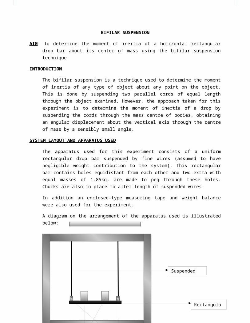
The apparatus used for this experiment consists of a uniform rectangular drop bar suspended by fine wires (assumed to have negligible weight contribution to the system). This rectangular bar contains holes equidistant from each other and two extra with equal masses of 1.85kg, are made to peg through these holes. Chucks are also in place to alter length of suspended wires.
In addition an enclosed-type measuring tape and weight balance were also used for the experiment.
A diagram on the arrangement of the apparatus used is illustrated below:
1.85Kg Masses
Suspended cord
Rectangular bar
Chucks
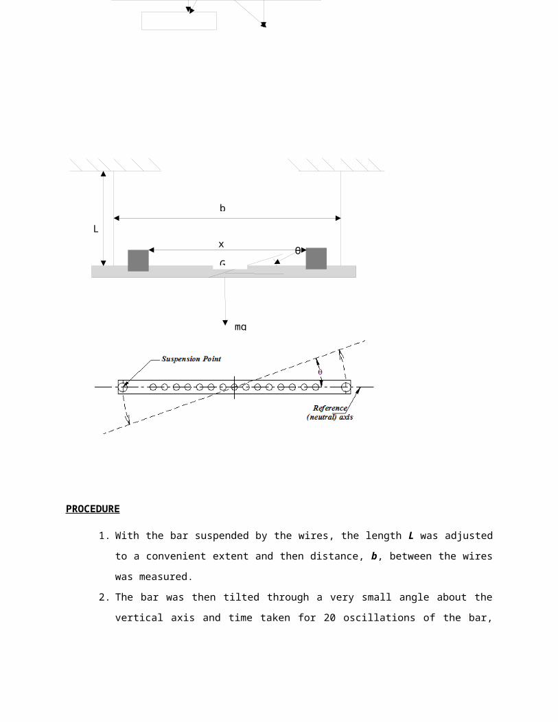
b
Ɵ
L
PROCEDURE
1. With the bar suspended by the wires, the length L was adjusted to a convenient extent and then distance, b, between the wires was measured.
2. The bar was then tilted through a very small angle about the vertical axis and time taken for 20 oscillations of the bar, was recorded. From this, the periodic time was also calculated.
3. The length L was further adjusted and the time taken for another 20 oscillations was recorded.
4. The inertia of the rectangular bar was then increased by including the “two 1.85kg masses” symmetrically on either side of the centerline distance x apart.
5. Then step 3 was repeated but with different values of L 6. The length of the wire L was then fixed at a value and the time taken was
recorded for 20 oscillations at varying distances x, between the two 1.85kg masses.
G
x
7. The rectangular bar was then detached from the apparatus arrangement and taken to weight balance in order to determine the mass of the bar.
8. The internal diameters of the holes, the thickness of the rectangular were also measured.
9. All measurements and data recorded were collated for experimental analysis.
THEORYTHE GOVERNING EQUATION – (THE EXPERIMENTAL ANALYSIS)
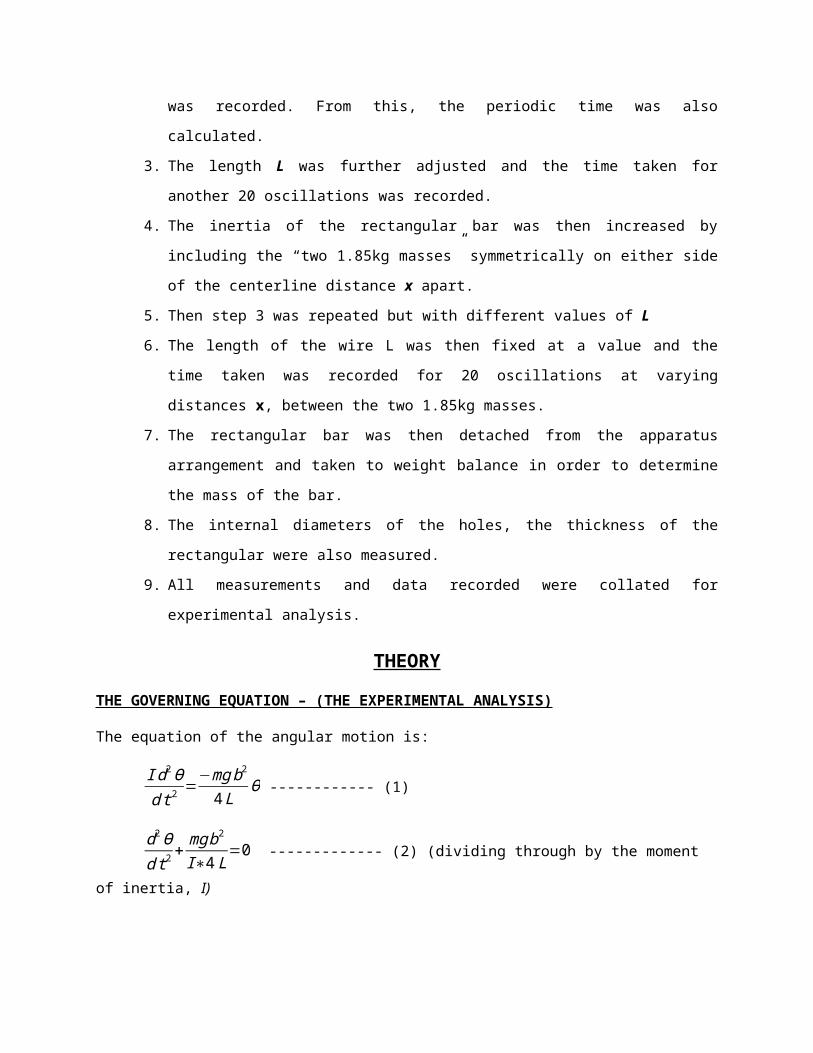
The equation of the angular motion is:
I d2Ɵdt 2
=−mgb2
4 LƟ ------------ (1)
d2Ɵd t2
+ mgb2
I∗4 L=0 ------------- (2) (dividing through by the moment of inertia, I)
Note that, I=mk2 (where ‘k’ is the radius of gyration and ‘m’ is mass of the bar)
So the above equation (2) may be written, as:
+gb2
4 k2LƟ=0 ------------- (3)
From equation (3),
ὥ=√ gb2
4k 2L Where ὥ is the angular velocity of the bar.
Also T = 2пὥ where T is the periodic time.
Therefore;
T=4п√ k2 Lgb2Also;
T=4п√ ILmg b2
---------- (4) (Since;I=mk2)
However, Introduction of the two equal masses into the bifilar suspension system can gives rise to a modification of its mechanism and the equation of the angular
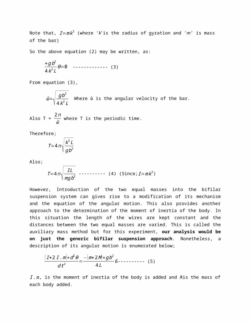
motion. This also provides another approach to the determination of the moment of inertia of the body. In this situation the length of the wires are kept constant and the distances between the two equal masses are varied. This is called the auxiliary mass method but for this experiment, our analysis would be on just the generic bifilar suspension approach. Nonetheless, a description of its angular motion is enumerated below;
(I+2 I .m )∗d2Ɵdt 2
=− (m+2M )∗gb2
4 LƟ---------- (5)
I .m, is the moment of inertia of the body is added and M is the mass of each body added.
I .m=12M r2+M x2
{r is the radius of the mass (it has a circular cross-section) and x is the distance between the centre of the bar and this mass)
From equation (5)
+ (m+2M )( I+2 I .m)
∗g b2
4 LƟ=0
Following the same approach from the previous period derivation, the new periodic time (inclusive of the new masses) becomes;
T .m=4п√ L
gb2∗( I+2 I .m)
(m+2M) ------------ (6)
THE ANALYTICAL APPROACH
The general approach for calculating the moment inertia of any type of body about any axis on the body is given as:
I=∫R2dm=∑ δm R2
Whereby individual moments of inertia from individual differential mass value δmand distance X between the axis point and the object are summed up and its summations gives rise to the final moment of inertia of that body.
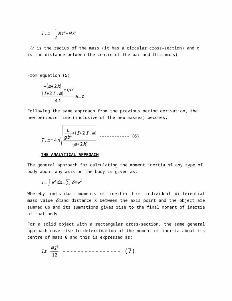
For a solid object with a rectangular cross-section, the same general approach gave rise to determination of the moment of inertia about its centre of mass G and this is expressed as;
Is=M l2
12 ---------------- (7)
Since the rectangular bar has bored holes within it, therefore its moment of inertia is;
I = Is (solid rectangular bar) - Io (bored holes).
Where Io is the moment of inertia of the bored holes.
Io=15( 12MoR o2)+2∗Mo∑ X 2 ------------- (8)
Where Mo is the mass of the hole bored, Ro is the radius of each hole bored and X is the distance from each hole (on either side) to the centre of the rectangular bar. Note the there are 15 holes bored, hence its introduction in equation (8)
Therefore, Moment of inertia of the bar, I is
I=M l2
12−[15Mo{(12 Ro2)+2∗∑ X 2}] ----------- (9)
However, Mo=ρпRo2t where (‘ρ’ is the density of the rectangular bar and‘t’ is the thickness of the rectangular bar)
Therefore the moment of inertia becomes,
I=M L2
12−¿ --------------- (10)

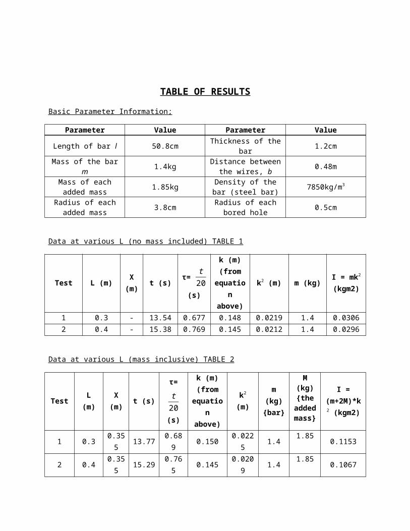
TABLE OF RESULTSBasic Parameter Information;
Parameter Value Parameter ValueLength of bar l 50.8cm Thickness of the
bar 1.2cm
Mass of the bar m 1.4kg Distance between the wires, b 0.48m
Mass of each added mass 1.85kg Density of the bar
(steel bar) 7850kg/m3
Radius of each added mass 3.8cm Radius of each
bored hole 0.5cm
Data at various L (no mass included) TABLE 1
Test L (m) X (m) t (s) τ= t20
(s)
k (m) (from
equation
above)
k2 (m) m (kg) I = mk2
(kgm2)
1 0.3 - 13.54 0.677 0.148 0.0219 1.4 0.03062 0.4 - 15.38 0.769 0.145 0.0212 1.4 0.0296
Data at various L (mass inclusive) TABLE 2
Test L (m) X (m) t (s)
τ= t20
(s)
k (m) (from
equation
above)
k2
(m)
m (kg) {bar
}
M (kg) {the adde
d mass
}
I = (m+2M)*
k2
(kgm2)
1 0.3 0.355 13.77 0.689 0.150 0.022
5 1.4 1.85 0.1153
2 0.4 0.355 15.29 0.765 0.145 0.020
9 1.4 1.85 0.1067
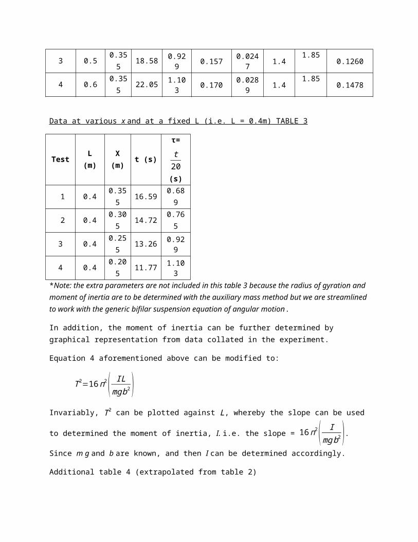
3 0.5 0.355 18.58 0.929 0.157 0.024
7 1.4 1.85 0.12604 0.6 0.35 22.05 1.103 0.170 0.028 1.4 1.85 0.1478
5 9
Data at various x and at a fixed L (i.e. L = 0.4m) TABLE 3
Test L (m)
X (m) t (s)
τ= t20
(s)
1 0.4 0.355 16.59 0.689
2 0.4 0.305 14.72 0.765
3 0.4 0.255 13.26 0.929
4 0.4 0.205 11.77 1.103
*Note: the extra parameters are not included in this table 3 because the radius of gyration and moment of inertia are to be determined with the auxiliary mass method but we are streamlined to work with the generic bifilar suspension equation of angular motion.
In addition, the moment of inertia can be further determined by graphical representation from data collated in the experiment.
Equation 4 aforementioned above can be modified to:
T 2=16п2( ILmg b2 )
Invariably, T 2 can be plotted against L, whereby the slope can be used to
determined the moment of inertia, I. i.e. the slope = 16п2( Imgb2 ). Since m g and b
are known, and then I can be determined accordingly.
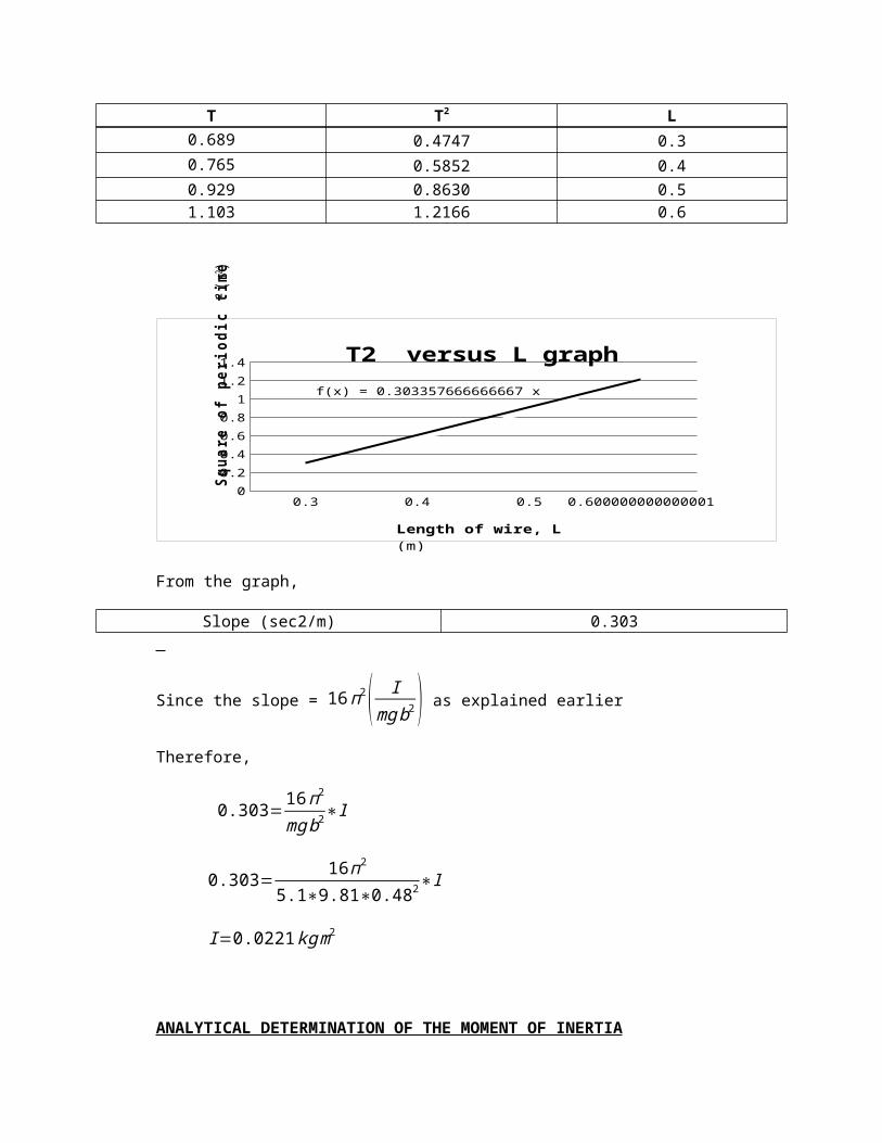
Additional table 4 (extrapolated from table 2)
T T2 L0.689 0.4747 0.30.765 0.5852 0.40.929 0.8630 0.51.103 1.2166 0.6
0.3 0.4 0.5 0.6000000000000010
0.2
0.4
0.6
0.8
1
1.2
1.4
f(x) = 0.303357666666667 x
T2 versus L graph
Squa
re o
f per
iodi
c tim
e T2 (s2 )
Length of wire, L (m)
From the graph,
Slope (sec2/m) 0.303
Since the slope = 16п2( Img b2 ) as explained earlier
Therefore,
0.303= 16п2
mgb2∗I
0.303= 16п2
5.1∗9.81∗0.482∗I
I=0.0221 kgm2
ANALYTICAL DETERMINATION OF THE MOMENT OF INERTIA
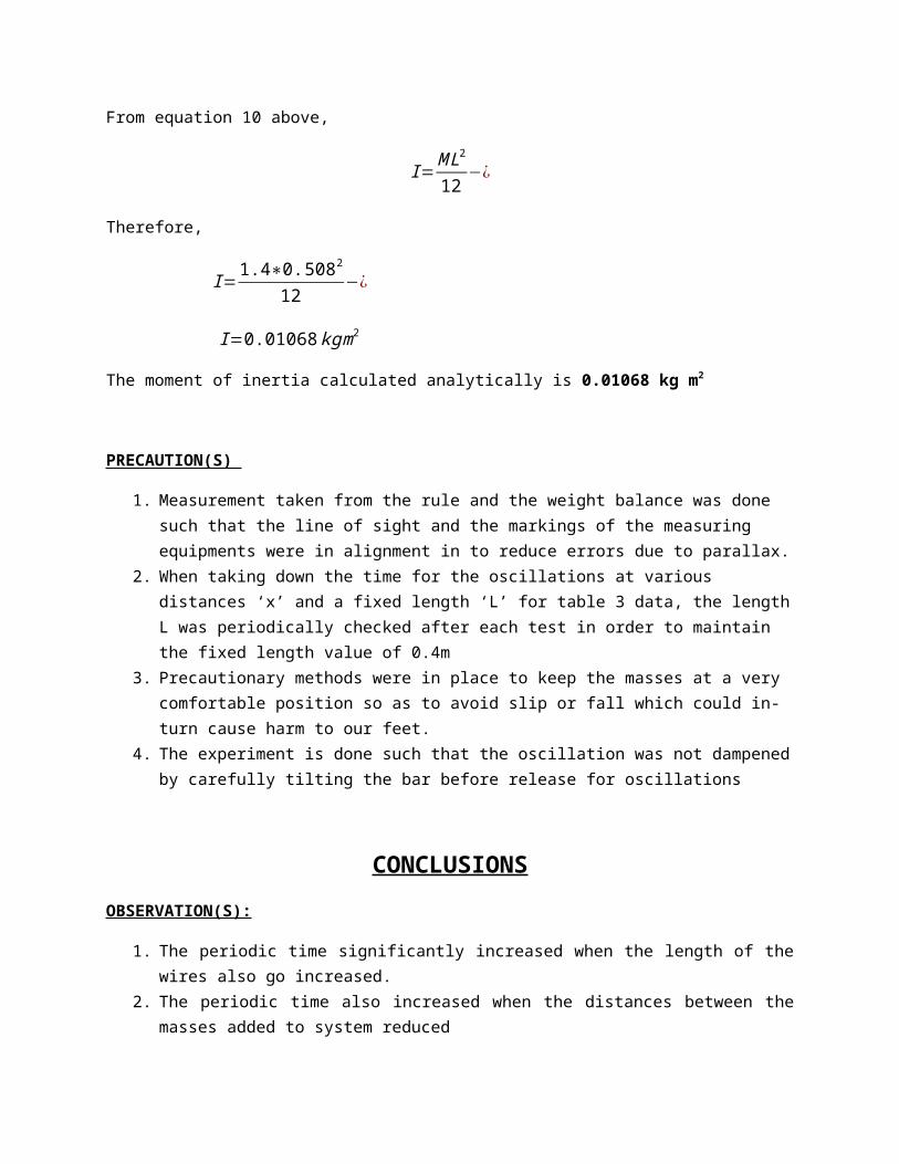
From equation 10 above,
I=M L2
12−¿
Therefore,
I=1.4∗0.5082
12−¿
I=0.01068kgm2
The moment of inertia calculated analytically is 0.01068 kg m2
PRECAUTION(S)
1. Measurement taken from the rule and the weight balance was done such that the line of sight and the markings of the measuring equipments were in alignment in to reduce errors due to parallax.
2. When taking down the time for the oscillations at various distances ‘x’ and a fixed length ‘L’ for table 3 data, the length L was periodically checked after each test in order to maintain the fixed length value of 0.4m
3. Precautionary methods were in place to keep the masses at a very comfortable position so as to avoid slip or fall which could in-turn cause harm to our feet.
4. The experiment is done such that the oscillation was not dampened by carefully tilting the bar before release for oscillations
CONCLUSIONSOBSERVATION(S):
1. The periodic time significantly increased when the length of the wires also go increased.
2. The periodic time also increased when the distances between the masses added to system reduced
3. The moment of inertia determined using the analytical approach was approximately equal to the value determined from test 2 in table 2 above.
4. The moment of inertia determined from the graph representation was greater than the value gotten from the analytical approach indicating that the two masses added during the experiment had a part to play in the increment of the moment of inertia and also unavoidable human errors caused a variation in their values.
5. The radius of gyration and moment of inertia reduced after the length of wire was increased from test 1 to test 2 but increased right after till test 4.
FINAL DEDUCTIONS:
The bifilar suspension technique offers the opportunity to determine the radius of gyration of a body by relating the readings gotten from the procedure in the techniques and relating that into the equation of angular and this invariably
provides the determination of the moment of inertia for the same body. These readings encompasses the distance between the wires used for the suspension, the length of the wires, the time for the required number of oscillations, the distance between the masses introduced into the experiment, and so on. All these and lots more provide the avenue for determining the radius of gyration and the moment of inertia
Below is a tabular representation of the final value of the moment of inertia determined from the analytical approach, the graphical approach and a selected value of the moment of inertia from test 2 in table 2.
Methodology Moment of inertia values
Analytical approach 0.01068 kg m2
Value from test 2 in table 2
0.01067 kg m2
Graphical approach 0.02210 kg m2