BFI Waste Systems of North America, Inc - National … · methodology proposed by P.K. Robertson...
20
3415 S. Sepulveda Blvd., Suite 500 Los Angeles, CA 90034 PH 310.957.6100 FAX 310.957.6101 www.geosyntec.com Technical Memorandum Date: October 8, 2015 To: Al Preston, Gesoyntec From: Jai Panthail, Rebecca Batchelder, Geosyntec Subject: West Basin Case Study Hydraulic Conductivity Field Testing Summary and Analysis Geosyntec Project: LA0324 Attachments 1. Geosyntec Consultants CPT Investigation Field Notes 2. Gregg Drilling and Testing, Inc. CPT Site Investigation Summary 3. Raw CPT and PPDT Data and Hydraulic Conductivity Calculations PROJECT BACKGROUND West Basin Municipal Utility District (West Basin) has contracted with Geosyntec Consultants (Geosyntec) to evaluate the feasibility of using a subsurface seawater intake (SSI) to supply feed water to a proposed desalination plant at 301 Vista Del Mar Blvd El Segundo, CA 90245. An important factor in evaluating the feasibility of using SSIs is the hydraulic conductivity of the sediments at the proposed project site. After reviewing existing data of the area, Geosyntec determined it would be necessary to conduct Cone Penetration Testing (CPT) and Pore Pressure Dissipation Testing (PPDT) at the proposed project site to get more accurate information on the site’s hydraulic conductivity. OBJECTIVE The objective of the fieldwork was to characterize stratigraphy and geotechnical properties of subsurface at El Segundo site to a depth of approximately 100 feet below ground surface (bgs). This technical memorandum present the results of the CPT and PPDT done at the El Segundo site and subsequent analysis of these data to determine the hydraulic conductivity of the sediment. The results of this analysis will be used to assist in evaluating the feasibility of different SSI technology at the proposed desal site. FIELD TESTING Field testing, consisting of three CPT borings and PPDT at one of the CPT boring locations, was conducted on August 31, 2015. A map of the CPT testing locations is shown in Figure 1. Drilling DRAFT
Transcript of BFI Waste Systems of North America, Inc - National … · methodology proposed by P.K. Robertson...

3415 S. Sepulveda Blvd., Suite 500 Los Angeles, CA 90034
PH 310.957.6100 FAX 310.957.6101
www.geosyntec.com
T e c h n i ca l M emo r a n d u m
Date: October 8, 2015
To: Al Preston, Gesoyntec
From: Jai Panthail, Rebecca Batchelder, Geosyntec
Subject: West Basin Case Study Hydraulic Conductivity Field Testing Summary and Analysis Geosyntec Project: LA0324
Attachments 1. Geosyntec Consultants CPT Investigation Field Notes
2. Gregg Drilling and Testing, Inc. CPT Site Investigation Summary
3. Raw CPT and PPDT Data and Hydraulic Conductivity Calculations
PROJECT BACKGROUND
West Basin Municipal Utility District (West Basin) has contracted with Geosyntec Consultants (Geosyntec) to evaluate the feasibility of using a subsurface seawater intake (SSI) to supply feed water to a proposed desalination plant at 301 Vista Del Mar Blvd El Segundo, CA 90245. An important factor in evaluating the feasibility of using SSIs is the hydraulic conductivity of the sediments at the proposed project site. After reviewing existing data of the area, Geosyntec determined it would be necessary to conduct Cone Penetration Testing (CPT) and Pore Pressure Dissipation Testing (PPDT) at the proposed project site to get more accurate information on the site’s hydraulic conductivity.
OBJECTIVE
The objective of the fieldwork was to characterize stratigraphy and geotechnical properties of subsurface at El Segundo site to a depth of approximately 100 feet below ground surface (bgs). This technical memorandum present the results of the CPT and PPDT done at the El Segundo site and subsequent analysis of these data to determine the hydraulic conductivity of the sediment. The results of this analysis will be used to assist in evaluating the feasibility of different SSI technology at the proposed desal site.
FIELD TESTING
Field testing, consisting of three CPT borings and PPDT at one of the CPT boring locations, was conducted on August 31, 2015. A map of the CPT testing locations is shown in Figure 1. Drilling
DRAFT

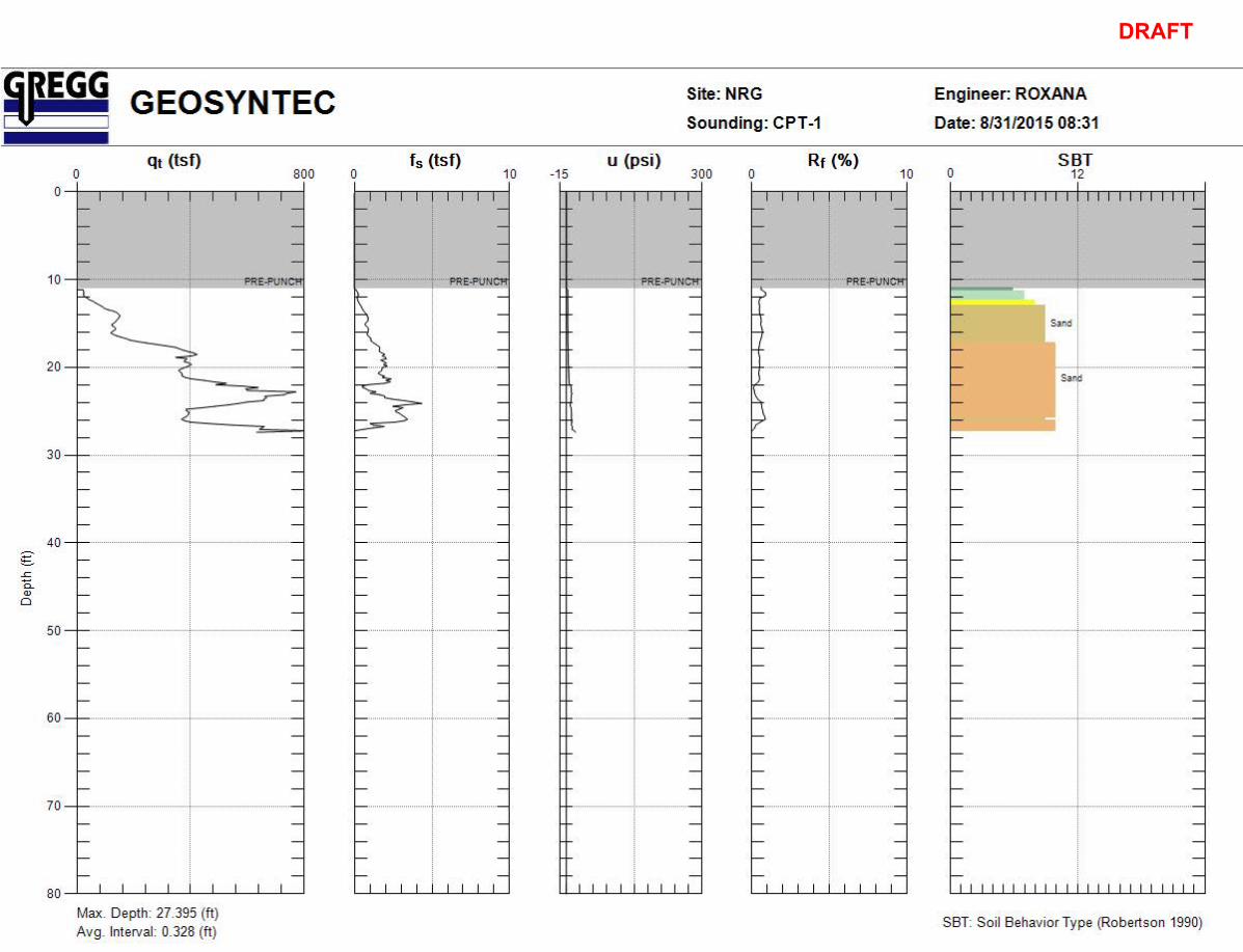
West Basin Case Study Hydraulic Conductivity Field Testing Summary and Analysis October 8, 2015 Page 2 was performed by Gregg Drilling and Testing, Inc. (Gregg Drilling). Representatives from West Basin and Gesoyntec were present to oversee the testing. Two of the CPTs (CPT-1 and CPT-2) hit refusal just before 30 feet below ground surface (bgs), and therefore no PPDT was conducted at these locations. The originally proposed CPT-3 location had to be changed due to access issues (see Figure 1). At the revised location, CPT-3 penetrated to a total of 81 feet bgs before hitting refusal. PPDT was conducted at the CPT-3 site every ten feet from 30 to 70 feet bgs, and then two more at 72 and 81.5 feet bgs.
The odor of hydrocarbons was noted during drilling of the first two CPTs just prior to hitting refusal.
Field notes and the preliminary results of the testing prepared by Gregg Drilling are provided in Attachments 1 and 2, respectively.
DRAFT

West Basin Case Study Hydraulic Conductivity Field Testing Summary and Analysis October 8, 2015 Page 3
DRAFT
West Basin Case Study Hydraulic Conductivity Field Testing Summary and Analysis October 8, 2015 Page 4 DETERMINATION OF HYDRAULIC CONDUCTIVITY
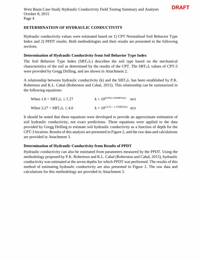
Hydraulic conductivity values were estimated based on 1) CPT Normalized Soil Behavior Type Index and 2) PPDT results. Both methodologies and their results are presented in the following sections.
Determination of Hydraulic Conductivity from Soil Behavior Type Index The Soil Behavior Type Index (SBTnIc) describes the soil type based on the mechanical characteristics of the soil as determined by the results of the CPT. The SBTnIc values of CPT-3 were provided by Gregg Drilling, and are shown in Attachment 2.
A relationship between hydraulic conductivity (k) and the SBTnIc has been established by P.K. Robertson and K.L. Cabal (Roberston and Cabal, 2015). This relationship can be summarized in the following equations:
When 1.0 < SBTnIc ≤ 3.27 k = 10(0.952-3.04SBTnIc) m/s
When 3.27 < SBTnIc ≤ 4.0 k = 10(-4.52 – 1.37SBTnIc) m/s
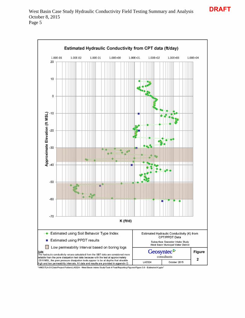
It should be noted that these equations were developed to provide an approximate estimation of soil hydraulic conductivity, not exact predictions. These equations were applied to the data provided by Gregg Drilling to estimate soil hydraulic conductivity as a function of depth for the CPT-3 location. Results of this analysis are presented in Figure 2, and the raw data and calculations are provided in Attachment 3.
Determination of Hydraulic Conductivity from Results of PPDT Hydraulic conductivity can also be estimated from parameters measured by the PPDT. Using the methodology proposed by P.K. Robertson and K.L. Cabal (Roberston and Cabal, 2015), hydraulic conductivity was estimated at the seven depths for which PPDT was performed. The results of this method of estimating hydraulic conductivity are also presented in Figure 2. The raw data and calculations for this methodology are provided in Attachment 3.
DRAFT
West Basin Case Study Hydraulic Conductivity Field Testing Summary and Analysis October 8, 2015 Page 5
DRAFT

West Basin Case Study Hydraulic Conductivity Field Testing Summary and Analysis October 8, 2015 Page 6 CONCLUSION
Estimates from both methodologies were found to be consistent, and indicated that at the CPT-3 location, two low permeability layers are present between 30 and 40 feet bgs and between 50 and 60 feet bgs.
The odor of hydro carbons noted during field investigations also indicates potential soil contamination which should be investigated further and taken into consideration during evaluation of SSI feasibility.
REFERENCES
Robertson, P.K. and Cabal (Robertson), K.L. (2015) Guide to Cone Penetration Testing for Geotechnical Engineering, 6th Edition. December
DRAFT

ATTACHMENT 1
GEOSYNTEC CONSULTANTS CPT INVESTIGATION FIELD NOTES
DRAFT

DRAFT

DRAFT

ATTACHMENT 2
GREGG DRILLING AND TESTING, INC. CPT SITE INVESTIGATION SUMMARY
DRAFT

DRAFT
DRAFT

DRAFT

DRAFT

DRAFT

DRAFT

ATTACHMENT 3
RAW CPT AND PPDT DATA AND HYDRAULIC CONDUCTIVITY CALCULATIONS
DRAFT

Depth (ft bgs)
Elev(ft MSL)
SBTn SBTnIcKsbt (ft/s)
Ksbt (ft/d)
Depth (ft bgs)
Elev(ft MSL)
SBTn SBTnIcKsbt (ft/s)
Ksbt (ft/d)
0.328 19.672 0 0 0.00E+00 0.00E+00 20.669 -0.669 6 1.51 9.80E-04 8.47E+010.656 19.344 0 0 0.00E+00 0.00E+00 20.997 -0.997 6 1.5 1.07E-03 9.24E+010.984 19.016 0 0 0.00E+00 0.00E+00 21.325 -1.325 6 1.48 1.29E-03 1.11E+021.312 18.688 0 0 0.00E+00 0.00E+00 21.654 -1.654 6 1.44 1.48E-03 1.28E+02
1.64 18.36 0 0 0.00E+00 0.00E+00 21.982 -1.982 6 1.44 1.64E-03 1.42E+021.969 18.031 0 0 0.00E+00 0.00E+00 22.31 -2.31 6 1.44 1.55E-03 1.34E+022.297 17.703 0 0 0.00E+00 0.00E+00 22.638 -2.638 6 1.46 1.45E-03 1.25E+022.625 17.375 0 0 0.00E+00 0.00E+00 22.966 -2.966 6 1.47 1.34E-03 1.16E+022.953 17.047 0 0 0.00E+00 0.00E+00 23.294 -3.294 6 1.48 1.22E-03 1.05E+023.281 16.719 0 0 0.00E+00 0.00E+00 23.622 -3.622 6 1.5 1.22E-03 1.05E+023.609 16.391 0 0 0.00E+00 0.00E+00 23.95 -3.95 6 1.47 1.21E-03 1.05E+023.937 16.063 0 0 0.00E+00 0.00E+00 24.278 -4.278 6 1.48 1.25E-03 1.08E+024.265 15.735 0 0 0.00E+00 0.00E+00 24.606 -4.606 6 1.5 1.21E-03 1.05E+024.593 15.407 0 0 0.00E+00 0.00E+00 24.934 -4.934 6 1.49 1.20E-03 1.04E+024.921 15.079 0 0 0.00E+00 0.00E+00 25.262 -5.262 6 1.5 1.23E-03 1.06E+025.249 14.751 0 0 0.00E+00 0.00E+00 25.591 -5.591 6 1.49 1.19E-03 1.03E+025.577 14.423 0 0 0.00E+00 0.00E+00 25.919 -5.919 6 1.51 1.12E-03 9.68E+015.906 14.094 0 0 0.00E+00 0.00E+00 26.247 -6.247 6 1.52 1.09E-03 9.42E+016.234 13.766 0 0 0.00E+00 0.00E+00 26.575 -6.575 6 1.51 1.16E-03 1.00E+026.562 13.438 0 0 0.00E+00 0.00E+00 26.903 -6.903 6 1.49 1.33E-03 1.15E+02
6.89 13.11 0 0 0.00E+00 0.00E+00 27.231 -7.231 6 1.47 1.46E-03 1.26E+027.218 12.782 0 0 0.00E+00 0.00E+00 27.559 -7.559 6 1.47 1.62E-03 1.40E+027.546 12.454 0 0 0.00E+00 0.00E+00 27.887 -7.887 6 1.45 2.53E-03 2.19E+027.874 12.126 0 0 0.00E+00 0.00E+00 28.215 -8.215 7 1.3 3.02E-03 2.61E+028.202 11.798 0 0 0.00E+00 0.00E+00 28.543 -8.543 7 1.39 5.40E-03 4.67E+02
8.53 11.47 0 0 0.00E+00 0.00E+00 28.871 -8.871 7 1.21 1.20E-02 1.04E+038.858 11.142 0 0 0.00E+00 0.00E+00 29.199 -9.199 7 0.95 0.00E+00 0.00E+009.186 10.814 0 0 0.00E+00 0.00E+00 29.528 -9.528 7 1.08 0.00E+00 0.00E+009.514 10.486 0 0 0.00E+00 0.00E+00 29.856 -9.856 7 1.2 1.67E-02 1.44E+039.843 10.157 0 0 0.00E+00 0.00E+00 30.184 -10.184 7 1.18 1.33E-02 1.15E+0310.17 9.829 0 0 0.00E+00 0.00E+00 30.512 -10.512 7 1.17 9.21E-03 7.96E+02
10.5 9.501 0 0 0.00E+00 0.00E+00 30.84 -10.84 7 1.33 4.81E-03 4.16E+0210.83 9.173 0 0 0.00E+00 0.00E+00 31.168 -11.168 7 1.43 2.79E-03 2.41E+0211.16 8.845 6 1.57 2.05E-04 1.77E+01 31.496 -11.496 7 1.41 2.72E-03 2.35E+0211.48 8.517 6 1.46 5.61E-04 4.85E+01 31.824 -11.824 7 1.34 4.24E-03 3.66E+0211.81 8.189 6 1.46 7.06E-04 6.10E+01 32.152 -12.152 7 1.24 7.19E-03 6.21E+0212.14 7.861 6 1.47 7.12E-04 6.15E+01 32.48 -12.48 7 1.25 9.80E-03 8.47E+0212.47 7.533 6 1.47 7.56E-04 6.53E+01 32.808 -12.808 7 1.25 1.12E-02 9.68E+02
12.8 7.205 6 1.45 7.51E-04 6.49E+01 33.136 -13.136 7 1.2 1.52E-02 1.31E+0313.12 6.877 6 1.49 6.85E-04 5.92E+01 33.465 -13.465 7 1.13 1.91E-02 1.65E+0313.45 6.549 6 1.52 6.05E-04 5.23E+01 33.793 -13.793 7 1.18 1.91E-02 1.65E+0313.78 6.22 6 1.52 5.40E-04 4.67E+01 34.121 -14.121 7 1.23 1.58E-02 1.37E+0314.11 5.892 6 1.55 4.40E-04 3.80E+01 34.449 -14.449 7 1.21 1.58E-02 1.37E+0314.44 5.564 6 1.63 3.10E-04 2.68E+01 34.777 -14.777 7 1.17 1.54E-02 1.33E+0314.76 5.236 6 1.69 2.11E-04 1.82E+01 35.105 -15.105 7 1.21 1.65E-02 1.43E+0315.09 4.908 6 1.71 1.72E-04 1.49E+01 35.433 -15.433 7 1.17 1.45E-02 1.25E+0315.42 4.58 6 1.72 1.69E-04 1.46E+01 35.761 -15.761 7 1.21 1.51E-02 1.30E+0315.75 4.252 6 1.71 1.93E-04 1.67E+01 36.089 -16.089 7 1.19 7.79E-03 6.73E+0216.08 3.924 6 1.67 2.19E-04 1.89E+01 36.417 -16.417 6 1.39 2.28E-03 1.97E+02
16.4 3.596 6 1.67 2.39E-04 2.06E+01 36.745 -16.745 6 1.68 5.47E-04 4.73E+0116.73 3.268 6 1.68 2.90E-04 2.51E+01 37.073 -17.073 6 1.84 1.93E-04 1.67E+0117.06 2.94 6 1.6 3.74E-04 3.23E+01 37.402 -17.402 6 1.81 1.37E-04 1.18E+0117.39 2.612 6 1.57 5.46E-04 4.72E+01 37.73 -17.73 6 1.8 1.58E-04 1.37E+0117.72 2.283 6 1.51 6.49E-04 5.61E+01 38.058 -18.058 6 1.8 1.56E-04 1.35E+0118.05 1.955 6 1.53 6.65E-04 5.75E+01 38.386 -18.386 6 1.82 1.38E-04 1.19E+0118.37 1.627 6 1.58 5.35E-04 4.62E+01 38.714 -18.714 6 1.86 1.14E-04 9.85E+00
18.7 1.299 6 1.62 4.52E-04 3.91E+01 39.042 -19.042 6 1.87 1.03E-04 8.90E+0019.03 0.971 6 1.61 4.64E-04 4.01E+01 39.37 -19.37 6 1.86 1.19E-04 1.03E+0119.36 0.643 6 1.58 5.76E-04 4.98E+01 39.698 -19.698 6 1.79 1.55E-04 1.34E+0119.69 0.315 6 1.54 7.43E-04 6.42E+01 40.026 -20.026 6 1.77 1.67E-04 1.44E+0120.01 -0.013 6 1.51 8.71E-04 7.53E+01 40.354 -20.354 6 1.85 1.59E-04 1.37E+0120.34 -0.341 6 1.51 9.36E-04 8.09E+01
* ca lculated us ing CPeT-IT v.1.6
Estimate of Hydraulic Conductivity Based on SBTnIc
In situ data Estimated k*In situ data Estimated k*
DRAFT

Depth (ft bgs)
Elev(ft MSL)
SBTn SBTnIcKsbt (ft/s)
Ksbt (ft/d)
Depth (ft bgs)
Elev(ft MSL)
SBTn SBTnIcKsbt (ft/s)
Ksbt (ft/d)
40.68 -20.682 6 1.82 1.38E-04 1.19E+01 61.024 -41.024 6 1.59 8.23E-04 7.11E+0141.01 -21.011 6 1.82 1.45E-04 1.25E+01 61.352 -41.352 6 1.73 5.32E-04 4.60E+0141.34 -21.339 6 1.83 1.36E-04 1.18E+01 61.68 -41.68 6 1.71 5.29E-04 4.57E+0141.67 -21.667 6 1.84 1.36E-04 1.18E+01 62.008 -42.008 6 1.57 8.65E-04 7.47E+01
42 -21.995 6 1.83 1.36E-04 1.18E+01 62.336 -42.336 6 1.58 1.65E-03 1.43E+0242.32 -22.323 6 1.83 1.41E-04 1.22E+01 62.664 -42.664 6 1.5 2.45E-03 2.12E+0242.65 -22.651 6 1.83 1.39E-04 1.20E+01 62.992 -42.992 7 1.42 5.37E-03 4.64E+0242.98 -22.979 6 1.84 1.35E-04 1.17E+01 63.32 -43.32 7 1.3 7.96E-03 6.88E+0243.31 -23.307 6 1.85 1.20E-04 1.04E+01 63.648 -43.648 7 1.38 4.38E-03 3.78E+0243.64 -23.635 6 1.88 1.04E-04 8.99E+00 63.976 -43.976 6 1.6 1.51E-03 1.30E+0243.96 -23.963 6 1.91 1.31E-04 1.13E+01 64.304 -44.304 6 1.67 7.93E-04 6.85E+0144.29 -24.291 6 1.76 6.85E-04 5.92E+01 64.633 -44.633 6 1.65 5.59E-04 4.83E+0144.62 -24.619 7 1.31 3.20E-03 2.76E+02 64.961 -44.961 6 1.74 5.26E-04 4.54E+0144.95 -24.948 7 1.29 1.13E-02 9.76E+02 65.289 -45.289 6 1.7 3.94E-04 3.40E+0145.28 -25.276 7 1.21 8.74E-03 7.55E+02 65.617 -45.617 6 1.75 2.78E-04 2.40E+01
45.6 -25.604 7 1.38 4.98E-03 4.30E+02 65.945 -45.945 6 1.86 2.28E-04 1.97E+0145.93 -25.932 6 1.51 2.48E-03 2.14E+02 66.273 -46.273 6 1.78 2.44E-04 2.11E+0146.26 -26.26 6 1.5 2.09E-03 1.81E+02 66.601 -46.601 6 1.72 4.00E-04 3.46E+0146.59 -26.588 7 1.44 2.74E-03 2.37E+02 66.929 -46.929 6 1.7 3.92E-04 3.39E+0146.92 -26.916 7 1.42 2.84E-03 2.45E+02 67.257 -47.257 6 1.78 4.28E-04 3.70E+0147.24 -27.244 7 1.49 2.63E-03 2.27E+02 67.585 -47.585 6 1.69 4.57E-04 3.95E+0147.57 -27.572 7 1.47 2.85E-03 2.46E+02 67.913 -47.913 6 1.68 6.15E-04 5.31E+01
47.9 -27.9 7 1.39 3.95E-03 3.41E+02 68.241 -48.241 6 1.67 5.05E-04 4.36E+0148.23 -28.228 7 1.36 2.65E-03 2.29E+02 68.57 -48.57 6 1.76 3.72E-04 3.21E+0148.56 -28.556 6 1.65 7.43E-04 6.42E+01 68.898 -48.898 6 1.79 4.56E-04 3.94E+0148.89 -28.885 6 1.84 3.67E-04 3.17E+01 69.226 -49.226 6 1.58 6.00E-04 5.18E+0149.21 -29.213 6 1.65 5.00E-04 4.32E+01 69.554 -49.554 6 1.66 5.56E-04 4.80E+0149.54 -29.541 6 1.53 8.42E-04 7.27E+01 69.882 -49.882 6 1.81 2.86E-04 2.47E+0149.87 -29.869 6 1.66 5.88E-04 5.08E+01 70.21 -50.21 6 1.84 1.72E-04 1.49E+01
50.2 -30.197 6 1.88 1.22E-04 1.05E+01 70.538 -50.538 6 1.87 9.83E-05 8.49E+0050.53 -30.525 5 2.16 1.15E-05 9.94E-01 70.866 -50.866 6 2.06 2.49E-05 2.15E+0050.85 -30.853 5 2.64 2.68E-06 2.32E-01 71.194 -51.194 5 2.6 2.70E-06 2.33E-0151.18 -31.181 5 2.38 4.08E-06 3.53E-01 71.522 -51.522 4 2.96 1.31E-07 1.13E-0251.51 -31.509 6 1.92 2.31E-05 2.00E+00 71.85 -51.85 4 2.75 6.43E-08 5.56E-0351.84 -31.837 6 1.98 6.15E-05 5.31E+00 72.178 -52.178 4 2.75 1.53E-07 1.32E-0252.17 -32.165 6 2.03 5.02E-05 4.34E+00 72.507 -52.507 4 2.74 1.20E-07 1.04E-0252.49 -32.493 6 1.99 4.79E-05 4.14E+00 72.835 -52.835 4 2.86 1.03E-07 8.90E-0352.82 -32.822 6 2 2.68E-05 2.32E+00 73.163 -53.163 4 2.82 8.97E-08 7.75E-0353.15 -33.15 5 2.31 7.41E-06 6.40E-01 73.491 -53.491 4 2.78 1.18E-07 1.02E-0253.48 -33.478 5 2.56 5.20E-06 4.49E-01 73.819 -53.819 4 2.75 1.21E-07 1.05E-0253.81 -33.806 6 2.1 3.86E-05 3.34E+00 74.147 -54.147 4 2.82 1.02E-07 8.81E-0354.13 -34.134 6 1.75 2.77E-04 2.39E+01 74.475 -54.475 4 2.84 8.81E-08 7.61E-0354.46 -34.462 6 1.63 8.38E-04 7.24E+01 74.803 -54.803 4 2.82 9.04E-08 7.81E-0354.79 -34.79 6 1.56 1.33E-03 1.15E+02 75.131 -55.131 4 2.8 1.00E-07 8.64E-0355.12 -35.118 6 1.53 1.60E-03 1.38E+02 75.459 -55.459 4 2.8 1.03E-07 8.90E-0355.45 -35.446 6 1.53 1.55E-03 1.34E+02 75.787 -55.787 4 2.81 1.17E-07 1.01E-0255.77 -35.774 6 1.56 6.86E-04 5.93E+01 76.115 -56.115 4 2.75 1.45E-07 1.25E-02
56.1 -36.102 6 1.87 1.14E-04 9.85E+00 76.444 -56.444 4 2.71 1.55E-07 1.34E-0256.43 -36.43 5 2.56 8.70E-06 7.52E-01 76.772 -56.772 4 2.77 2.54E-07 2.19E-0256.76 -36.759 4 2.7 3.72E-07 3.21E-02 77.1 -57.1 5 2.57 6.70E-07 5.79E-0257.09 -37.087 4 2.56 4.29E-07 3.71E-02 77.428 -57.428 5 2.41 1.01E-06 8.73E-0257.42 -37.415 5 2.55 1.05E-06 9.07E-02 77.756 -57.756 5 2.54 9.16E-07 7.91E-0257.74 -37.743 5 2.4 1.36E-05 1.18E+00 78.084 -58.084 5 2.57 7.83E-07 6.77E-0258.07 -38.071 6 1.88 1.02E-04 8.81E+00 78.412 -58.412 4 2.48 5.84E-07 5.05E-02
58.4 -38.399 6 1.69 3.39E-04 2.93E+01 78.74 -58.74 4 2.66 2.77E-07 2.39E-0258.73 -38.727 6 1.69 5.39E-04 4.66E+01 79.068 -59.068 4 2.81 7.46E-07 6.45E-0259.06 -39.055 6 1.67 5.93E-04 5.12E+01 79.396 -59.396 5 2.31 8.21E-06 7.09E-0159.38 -39.383 6 1.65 6.83E-04 5.90E+01 79.724 -59.724 6 1.94 1.20E-04 1.04E+0159.71 -39.711 6 1.67 9.15E-04 7.91E+01 80.052 -60.052 6 1.54 1.10E-03 9.50E+0160.04 -40.039 6 1.58 1.28E-03 1.11E+02 80.381 -60.381 7 1.42 6.64E-03 5.74E+0260.37 -40.367 6 1.53 1.75E-03 1.51E+02 80.709 -60.709 7 1.33 1.26E-02 1.09E+03
60.7 -40.696 6 1.52 1.54E-03 1.33E+02 81.037 -61.037 7 1.28 2.42E-02 2.09E+03
* ca lculated us ing CPeT-IT v.1.6
In situ data Estimated k*Estimated k*In situ data
DRAFT

1. 𝛼𝛼𝑀𝑀 = 0.0188 ∙ �10(0.55𝑆𝑆𝑆𝑆𝑇𝑇𝑛𝑛𝐼𝐼𝑐𝑐+1.68)� 𝑓𝑓𝑓𝑓𝑓𝑓 𝑆𝑆𝑆𝑆𝑇𝑇𝑛𝑛𝐼𝐼𝑐𝑐 < 2.2 (𝑐𝑐𝑓𝑓𝑐𝑐𝑓𝑓𝑐𝑐𝑐𝑐 𝑔𝑔𝑓𝑓𝑐𝑐𝑔𝑔𝑛𝑛𝑐𝑐𝑔𝑔 𝑐𝑐𝑓𝑓𝑔𝑔𝑠𝑠𝑐𝑐)
𝛼𝛼𝑀𝑀 = 14 𝑓𝑓𝑓𝑓𝑓𝑓 𝑆𝑆𝑆𝑆𝑇𝑇𝑛𝑛𝐼𝐼𝑐𝑐 > 2.2 𝑐𝑐𝑛𝑛𝑔𝑔 𝑞𝑞𝑡𝑡 > 14 𝑡𝑡𝑐𝑐𝑓𝑓 (𝑓𝑓𝑔𝑔𝑛𝑛𝑐𝑐 𝑔𝑔𝑓𝑓𝑐𝑐𝑔𝑔𝑛𝑛𝑐𝑐𝑔𝑔 𝑐𝑐𝑓𝑓𝑔𝑔𝑠𝑠𝑐𝑐)
2. 𝑀𝑀 = 𝛼𝛼𝑀𝑀(𝑞𝑞𝑡𝑡 − 𝜎𝜎𝑣𝑣𝑣𝑣) 3. 𝑃𝑃𝑓𝑓𝑓𝑓𝑐𝑐 𝑝𝑝𝑓𝑓𝑐𝑐𝑐𝑐𝑐𝑐𝑝𝑝𝑓𝑓𝑐𝑐 𝑐𝑐𝑡𝑡 𝑡𝑡100 =
(𝑡𝑡𝑐𝑐𝑐𝑐𝑡𝑡 𝑔𝑔𝑐𝑐𝑝𝑝𝑡𝑡ℎ − 𝑤𝑤𝑐𝑐𝑡𝑡𝑐𝑐𝑓𝑓 𝑡𝑡𝑐𝑐𝑡𝑡𝑠𝑠𝑐𝑐 𝑔𝑔𝑐𝑐𝑝𝑝𝑡𝑡ℎ) ∙ 𝑐𝑐𝑝𝑝𝑐𝑐𝑐𝑐𝑔𝑔𝑓𝑓𝑔𝑔𝑐𝑐 𝑤𝑤𝑐𝑐𝑔𝑔𝑔𝑔ℎ𝑡𝑡 𝑓𝑓𝑓𝑓 𝑤𝑤𝑐𝑐𝑡𝑡𝑐𝑐𝑓𝑓 4. 𝑃𝑃𝑓𝑓𝑓𝑓𝑐𝑐 𝑝𝑝𝑓𝑓𝑐𝑐𝑐𝑐𝑐𝑐𝑝𝑝𝑓𝑓𝑐𝑐 𝑐𝑐𝑡𝑡 𝑡𝑡50 = (𝑡𝑡0−𝑡𝑡100)
2+ 𝑡𝑡100
5. 𝑐𝑐 = �𝑇𝑇50𝑡𝑡50� 𝑓𝑓𝑣𝑣2
6. 𝑘𝑘 = 𝑐𝑐∙𝛾𝛾𝑤𝑤𝑀𝑀
Pene-trometer
radius
Pene-trometer
radius
Specific weight of
water
Specific weight of
water
Water table depth
T90 T50 ro ro γw γw
(unitless) (unitless) (cm) (ft) (lb/ft3) (ton/ft3) (ft)0.850 0.197 1.09 0.036 62.43 0.03 20.00
Test Depth
Corrected Cone
Resistence, qt
Total Over-
burden Stress, σv
Soil Behavior
Type Index, SBTnIc
αM1 Constrain-
ed Modulus,
M2
Pore pressure at t100
3
Pore pressure
at t0
Pore pressure
at t504
Time for 50%
dissipa-tion, t50
Coeffi-cient of Consoli-
dation, c5
(ft bgs) (tsf) (tsf) (unitless) (unitless) (tsf) (PSI) (PSI) (PSI) (sec) (ft2/sec) (ft/sec) (ft/day)30.02 594 1.889 1.10 3.62 2146.86 4.3 18 11.2 80 3.16E-06 2.12E-04 1.83E+0140.03 281 2.509 1.73 8.05 2240.34 8.7 21 14.8 82 3.09E-06 2.16E-04 1.86E+0150.03 225 3.148 1.77 8.47 1879.55 13.0 28 20.5 85 2.98E-06 1.75E-04 1.51E+0160.04 387 3.754 1.43 5.50 2107.08 17.4 52 34.7 202 1.25E-06 8.24E-05 7.12E+0070.05 428 4.397 1.72 NA NA NA 19* NA NA NA NA NA72.01 29 4.513 2.72 14.00 340.72 22.5 160 91.3 1641 1.54E-07 1.64E-06 1.42E-0181.20 564 5.043 1.01 3.23 1807.87 26.5 37 31.9 20 5.46E-05 3.08E-03 2.66E+02
* invalid data, not used
Theoretical time factors
Estimate of Hydraulic Conductivity Based on PPDT Data
Hydraulic Conductivity, k6
Test data
LEGEND
Constant
Calculated
DRAFT