Beyond Movable Walls Installation Guide...3 Beyond installation overview This guide outlines the...
86
Beyond Movable Walls Installation Guide
Transcript of Beyond Movable Walls Installation Guide...3 Beyond installation overview This guide outlines the...

Beyond Movable Walls Installation Guide

2
Introduction . . . . . . . . . . . . . . . . . . . . . . . . . . . . . . . . . . . . . . . . . . . . . . . . . . . . . . 3Recommended Tools . . . . . . . . . . . . . . . . . . . . . . . . . . . . . . . . . . . . . . . . . . . . . . . . 4-8
General 4Suction Cups and Chop Saw 5Blade and Carts 6A Frames and Ladders/Baker Carts 7Laser and Hex Drive 8
Shipping Documentation . . . . . . . . . . . . . . . . . . . . . . . . . . . . . . . . . . . . . . . . . . . . . . 9-15Labels 9Receiving Paperwork 10-11
Packaging 12-15
Proper Handling/Staging . . . . . . . . . . . . . . . . . . . . . . . . . . . . . . . . . . . . . . . . . . . . . 16-18Panels/Doors 16Fillers and Trim 17Privacy Tiles 18
Ceiling Channel . . . . . . . . . . . . . . . . . . . . . . . . . . . . . . . . . . . . . . . . . . . . . . . . . . 19-26Layout 19Mounting Clips 20Installation 21Connections 22-25Special Conditions 26
Wall Channels . . . . . . . . . . . . . . . . . . . . . . . . . . . . . . . . . . . . . . . . . . . . . . . . . . . 27-29Frameless Glass 27Small and Large 28Adjacent Door 29
Setting Panel Height . . . . . . . . . . . . . . . . . . . . . . . . . . . . . . . . . . . . . . . . . . . . . . . 30-32
Frameless Glass . . . . . . . . . . . . . . . . . . . . . . . . . . . . . . . . . . . . . . . . . . . . . . . . . . 33-52Standing Panels 33Leveling 34Vertical Fillers 35-40Adapters 41-42Trim 43-45Rail-Mounted Privacy 46-49Button-Mounted Privacy 50-52
Framed Glass/Solid Wall . . . . . . . . . . . . . . . . . . . . . . . . . . . . . . . . . . . . . . . . . . . . . 53-58Standing Panels 53Leveling 54Posts 55-56Zippers 57Base Trim 58
Doors . . . . . . . . . . . . . . . . . . . . . . . . . . . . . . . . . . . . . . . . . . . . . . . . . . . . . . . . 59-78Sliding Door 59-67Pivot Frameless Glass Door 68-75Hardware 76Biloba Hinges 77-78
Miscellaneous . . . . . . . . . . . . . . . . . . . . . . . . . . . . . . . . . . . . . . . . . . . . . . . . . . . 79-85Electrical 79Privacy Shelves 80Horizontal Brackets 81Vertical Brackets 82Stacking 83Care and Maintenance Instructions 84-85
Table of Contents
If you have any questions, please contact [email protected].
3
Beyond installation overview
This guide outlines the installation process
for Beyond Movable Walls. It is a general
guide to help assist our partners in
preparing for a typical installation.
The guide is only useful when working
in combination with an approved fl oor
plan. It will provide a reference of proper
techniques when installing Beyond
components per the plan. The fl oor
plan may denote if applicable for the
project, special conditions not noted
in this guide. These special conditions
should be reviewed with appropriate
project manager prior to installation
commencement.
The guide should be completely reviewed
prior to beginning the installation.
Beyond product overview
Having an understanding of the Beyond
Statement of Line and nomenclature will
help facilitate information fl ow.
Prior to installing it is recommended to
review the Beyond Specifi cation Guide
detailing common defi nitions, acronyms
and model descriptions.
Projects requiring seismic
Due to local and national building codes/
conditions, please refer to Allsteel seismic
documents when applicable for more
information.
Introduction
If you have any questions, please contact [email protected].
4
Recommended Tools — General
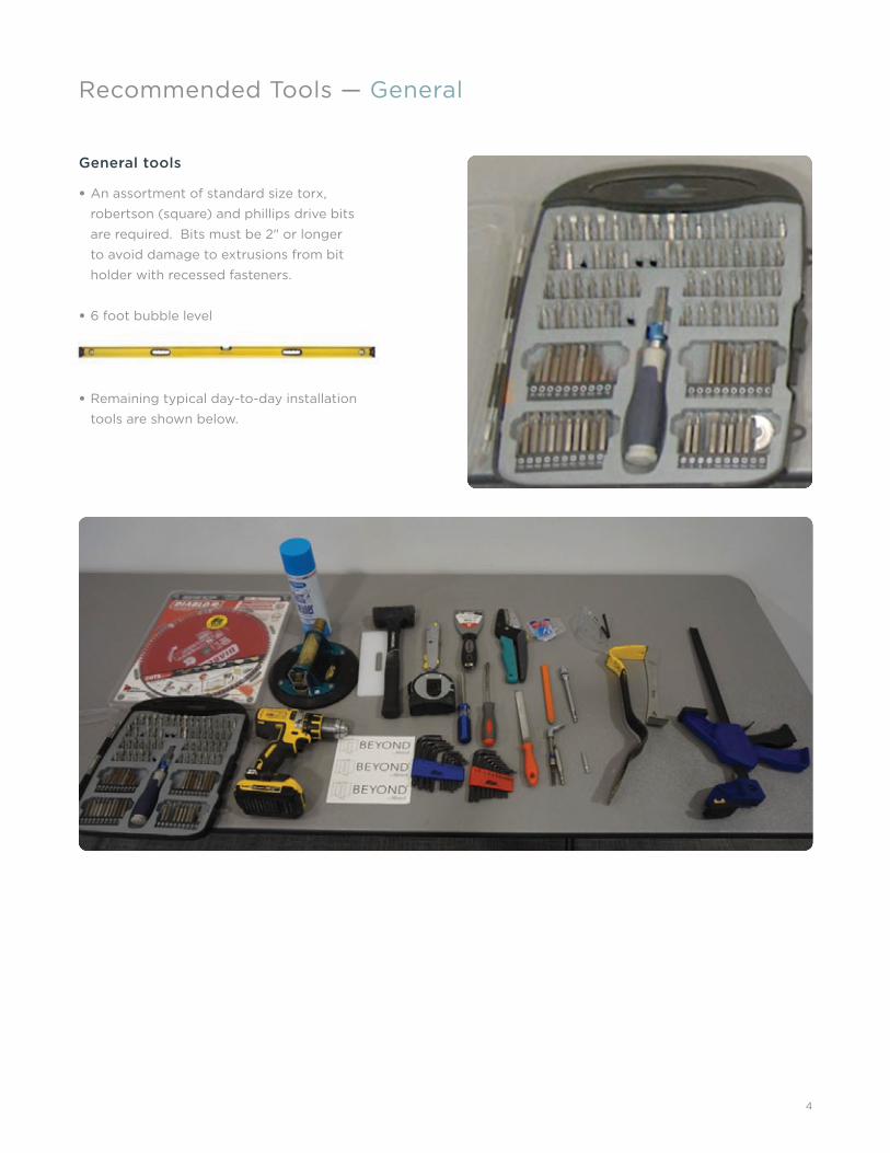
General tools
• An assortment of standard size torx,
robertson (square) and phillips drive bits
are required. Bits must be 2" or longer
to avoid damage to extrusions from bit
holder with recessed fasteners.
• 6 foot bubble level
• Remaining typical day-to-day installation
tools are shown below.

5
Suction cups
Woods power grip N4950
• The standard tool of the glass industry, the
N4950 Vacuum Cup features an all-metal
pump and handle for maximum durability
in the shop or at the installation site. Its fl at
vacuum pad is ideal for handling all kinds
of windows and other fl at glass products.
Supplied with protective carrying case. 8"
[20 cm] diameter. 125 lbs [57 kg] capacity
per vacuum cup.
• Recommended minimum quantity:
– 6-8.
– May require more depending upon
job size.
Chop saw
• 12" miter/chop saw recommended.
• There are many makes/models, choose a
good quality mid-priced saw.
• Good fi t and fi nish require a good
combination of saw and saw blade.
Recommended Tools — Suction Cups and Chop Saw

6
Saw blade
• Diablo D1296N - Contractor Stationary Blade
(Coated) 12 x 96 Tcg Ultra Finish/Non Ferrous/
Plastic.
– Item # FRD1296N
• Available at major retailers.
Recommended Tools — Blade and Carts
Carts
• Drywall style carts are recommended
due to stability.
• Keeps center of gravity near center of cart.
• Typical furniture handling type carts are
unstable with one panel on cart due to
center of gravity being close to edge of cart.
• Recommended quantity:
– 6-8 minimum.
NOT RECOMMENDED

7
A frames
• A frames are useful when short term storage
of panels is needed.
• They are constructed with common lumber
and padded for protection of panels.
• Recommended minimum quantity:
– 6-8.
– May require more depending upon
job size.
Recommended Tools — A Frames and Ladders/Baker Carts
Ladders/baker carts
• Step Ladders
– Recommend 6 ft Ladder.
– Recommended quantity:
– 3-5.
• Baker Carts
– Recommend folding collapsible type
for ease of moving.
– Recommended quantity:
– 3-5.
• Either one or a combination of both works.

8
Multiaxis line laser
• Lasers projecting only a dot are
not acceptable.
• Lasers projecting at least a vertical AND a
horizontal line are acceptable.
• Lasers projecting three axes lines are
recommended. These type lasers project
two perpendicular lines allowing the layout
of a 90 degree corner in one set up.
• Recommended minimum quantity:
– 2
Recommended Tools — Laser and Hex Drive
¼'' Hex drive
• Can be as simple as ratchet with ¼'' socket.
• For use with a drill a 90 degree drive
attachment or universal joint will be needed.
• Optional power ratchet.
BEST
NOT ACCEPTABLEBETTER

9
Shipping Documentation — Labels
Both shipping labels contain the same information:
• Customer PO
• Receivers PO
• Allsteel Order Number
• Load Number
• Stop Number
• Product or Model Number
• Ship to
– Mark For
– Tag Lines
New shipping labels contain:
• From
• Carrier
• Ship to Post Barcode

10
Every load/stop on a trailer has a packet containing circle sheets.
• Circle sheets contain the carton number for each piece on the delivery.
• Each customer purchase order has the associated carton numbers in a list next to it.
• Carton numbers are not in order on the circle sheet.
• If you are done unloading the trailer and have unmarked carton numbers, you can refer to the purchase order
(packing list) to research what you may have missed and check the like containers for the carton.
Shipping Documentation — Receiving Paperwork
11
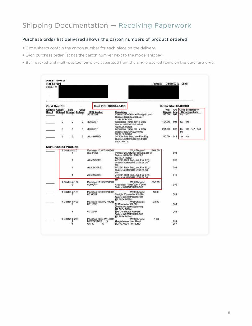
Purchase order list delivered shows the carton numbers of product ordered.
• Circle sheets contain the carton number for each piece on the delivery.
• Each purchase order list has the carton number next to the model shipped.
• Bulk packed and multi-packed items are separated from the single packed items on the purchase order.
Shipping Documentation — Receiving Paperwork

12
Single packs
• Contain one piece of the specifi ed model
number in the package.
Bulk packs
• Contain multiple pieces of the same model
number. Examples like tiles or connectors.
Multi-packs
• Contain several diff erent model numbers.
Examples of this are electrical components
and worksurfaces.
Shipping Documentation — Packaging

13
Shipping Documentation — Single Packs
• One product label on the carton.
• One unit of product in the carton.
• Shipping label carton number matches the
carton number on the purchase order.
• If you are missing a carton number after
unloading, the single packed pieces show
the carton number after the model number
on the purchase order.
• Multiple carton numbers may be at the end of one line item.

14
• Usually one product label on one carton or
pallet containing a piece count with one
shipping label.
Shipping Documentation — Bulk Packs
• On occasion multiple single pack labels
will be used on one box or pallet with one
shipping label.
• Shipping label carton number matches the
carton number on the purchase order.
• If you are missing a carton number after unloading,
Bulk packed product show the carton number at the front of the sheet.

15
• Multi-packs consist of mixed models in one
carton or pallet.
• Usually one product label on one carton or
pallet one shipping label.
Shipping Documentation — Multi-Packs
• On occasion multiple single pack labels
will be used on one box or pallet with one
shipping label containing a list of product.
• Shipping label carton number matches the
carton number on the purchase order.
• If you are missing a carton number after
unloading, multi-packed product show the
carton number at the front of the sheet.

16
Proper Handling/Staging — Panels/Doors
Glass edge protection must be used at all times.
• Avoid point contact with glass edges.
• Glass will ship with edge protection.
• Keep on glass until panels are stood up.
Panels must not rest on floor channel corners.
• Floor channel fl ange will be bent creating
diffi culty in installing carpet gripper.
• Rest panel along long edge of fl oor channel
then stand up.
Glass panels are heavy and may cause damage during staging.
• Use caution in staging multiple panels and
possibly damaging building.

17
Proper Handling/Staging — Fillers and Trim
• Fillers and trim need to be handled
with care.
• Use caution when parts are in contact with
each other, sliding on one another will cause
scratches.
• The action of pulling parts out of the box will
cause scratching.
– Box should be opened to allow trim to be
removed without sliding.
Stage these items horizontally on racks or neatly out of the way on the fl oor.

18
Privacy tiles are extremely susceptible to damage.
• Tiles should be staged vertically back to
back, face to face. They are best stored and
staged from their bulk pack boxes.
Proper Handling/Staging — Privacy Tiles
• Hands must be clean when handling tiles.
• Do not stage product against tiles.
• Do not grab too many tiles at one time to
prevent bending the tiles.

19
Ceiling Channel — Layout
Using Allsteel provided drawings, layout ceiling channel.
• Layout drawings show centerline to
centerline dimensions unless noted.
• Ceiling channel has a groove showing
the centerline for ease of aligning to laser
layout lines.
• Ensure 90 degree corners during layout.
• Do not assume grid to be parallel with
layout.
• Check fi t and strength. Verify accuracy of
all measurements. Laser down for panel
centerline and snap chalk lines.
Grid clip layout:
• Using the layout laser line, install and align
clips along laser line, install spacer, and
tighten (do not over tighten).
20
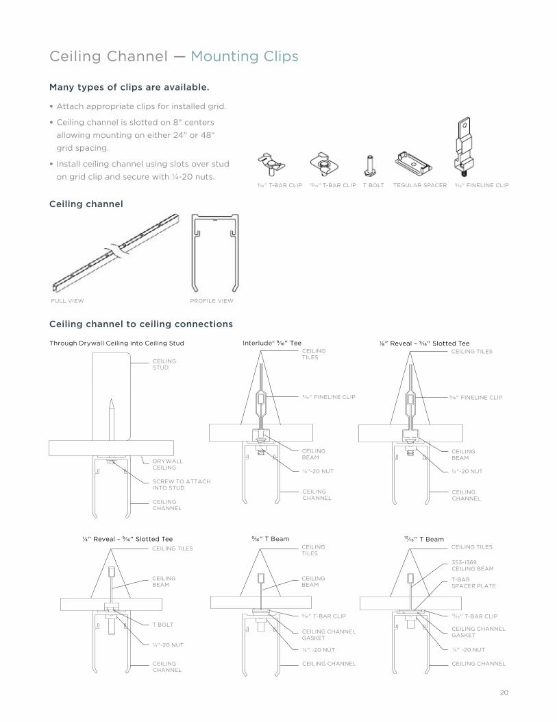
Many types of clips are available.
• Attach appropriate clips for installed grid.
• Ceiling channel is slotted on 8" centers
allowing mounting on either 24" or 48"
grid spacing.
• Install ceiling channel using slots over stud
on grid clip and secure with ¼-20 nuts.
Ceiling Channel — Mounting Clips
Ceiling channel
Ceiling channel to ceiling connections
CEILING STUD
9⁄16" FINELINE CLIP 9⁄16" FINELINE CLIP
CEILING BEAM
CEILING BEAM
353-I369 CEILING BEAM
DRYWALL CEILING
CEILING BEAM
CEILING BEAM
T BOLTCEILING CHANNEL GASKET
CEILING CHANNEL GASKET
9⁄16" T-BAR CLIP 15⁄16" T-BAR CLIP
T-BAR SPACER PLATE
SCREW TO ATTACH INTO STUD
¼"-20 NUT ¼"-20 NUT
¼"-20 NUT¼" -20 NUT ¼" -20 NUT
CEILING CHANNEL
CEILING CHANNEL
CEILING CHANNEL
CEILING CHANNEL
CEILING CHANNEL CEILING CHANNEL
Through Drywall Ceiling into Ceiling Stud
¼" Reveal – 9⁄16" Slotted Tee 9⁄16" T Beam 15⁄16" T Beam
Interlude® 9⁄16" Tee CEILING TILES
CEILING TILES
CEILING TILES CEILING TILES
CEILING TILES
⅛" Reveal – 9⁄16" Slotted Tee
FULL VIEW PROFILE VIEW
9⁄16" T-BAR CLIP 15⁄16" T-BAR CLIP T BOLT TEGULAR SPACER 9⁄16" FINELINE CLIP

21
Attaching to drywall/hidden grid.
• Requires direct attachment of the channel
with screws or anchors.
Attaching to ceiling grid.
• Many ceiling grids accept standard mounting
clips as shown on previous page.
• When the grid is recessed, please use
spacer(s) to prevent sound loss and light
gap.
General notes:
• Installer supplied fasteners appropriate
to the material are to be used for ceiling
channel attachment.
• Ceiling channel is attached to the ceiling
aligning with laser line used in layout.
• If ceiling is not stable, blocking or
reinforcement may be necessary through
use of structural materials above the
tiles. This work is not included in the
installation bid.
• Accurate installation of ceiling channel is
critical to a satisfactory installation. Please
contact Allsteel with any discrepancies.
Ceiling Channel — Installation
22
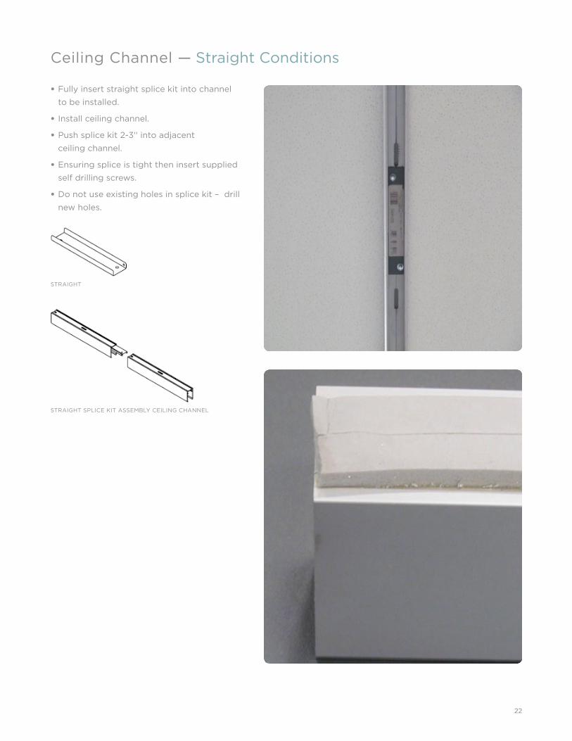
• Fully insert straight splice kit into channel
to be installed.
• Install ceiling channel.
• Push splice kit 2-3'' into adjacent
ceiling channel.
• Ensuring splice is tight then insert supplied
self drilling screws.
• Do not use existing holes in splice kit – drill
new holes.
Ceiling Channel — Straight Conditions
STRAIGHT SPLICE KIT ASSEMBLY CEILING CHANNEL
STRAIGHT

23
Corner 45 degree miters are field cut.
• Install two-way splice kit in either the
installed or to be installed ceiling channel.
• Insert other end of splice plate into ceiling
channel and install ceiling channel.
• Ensuring splice is tight, insert supplied self
drilling screws.
• Do not use existing holes in splice kit –
drill new holes.
Ceiling Channel — Two-Way Conditions
TWO-WAY
24
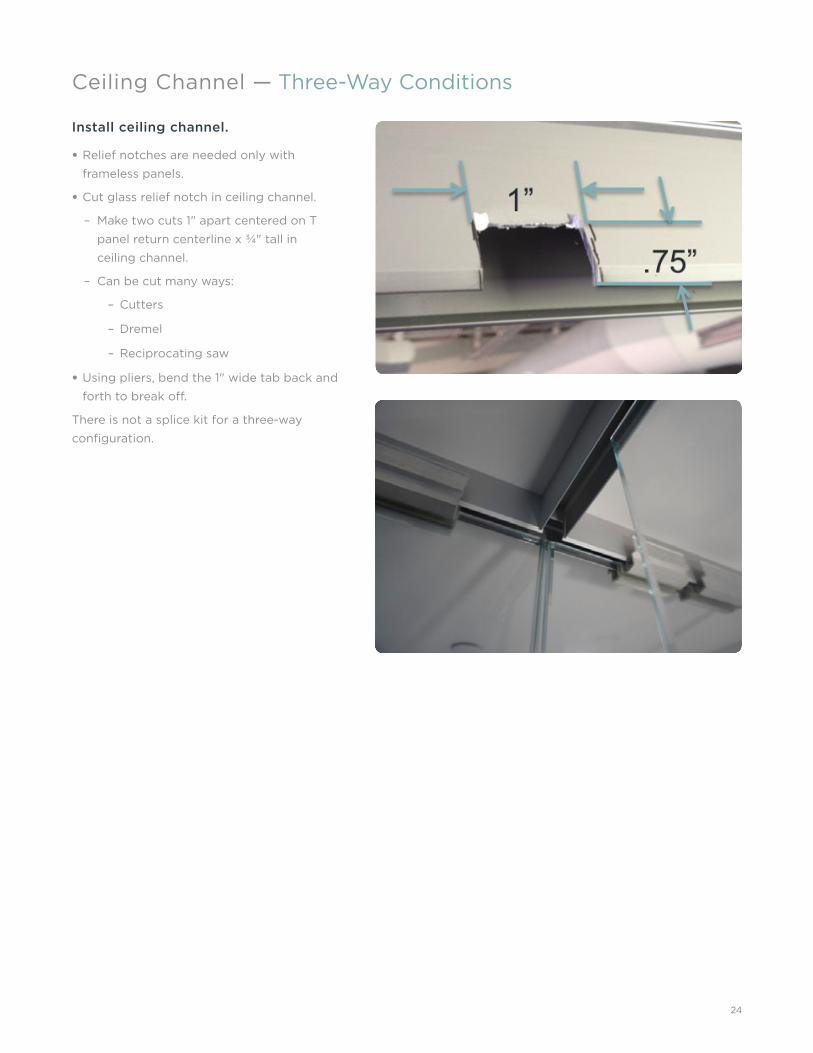
Ceiling Channel — Three-Way Conditions
Install ceiling channel.
• Relief notches are needed only with
frameless panels.
• Cut glass relief notch in ceiling channel.
– Make two cuts 1" apart centered on T
panel return centerline x ¾" tall in
ceiling channel.
– Can be cut many ways:
– Cutters
– Dremel
– Reciprocating saw
• Using pliers, bend the 1" wide tab back and
forth to break off .
There is not a splice kit for a three-way
confi guration.

25
Ceiling Channel — Four-Way Conditions
Install ceiling channel.
• Relief notches are needed only with
frameless panels.
• Cut glass relief notch in ceiling channel.
– Make two cuts 1" apart centered on T
panel return centerline x ¾" tall in
ceiling channel.
– Can be cut many ways:
– Cutters
– Dremel
– Reciprocating saw
• Using pliers, bend the 1" wide tab back and
forth to break off .
There is not a splice kit for a four-way
confi guration.

26
Ceiling Channel — Special Conditions
END TRIM - SLIDE INTO CEILING CHANNEL AND
ATTACH WITH THE SCREWS FROM BELOW
135-DEGREE SPLICE KIT
CEILING CHANNEL END CAP FOR USE WITH FINISHED END

27
For use with frameless glass only.
Attaching the wall channel.
• Measure fl oor to bottom of ceiling channel.
• Cut wall channel to fl oor to bottom of ceiling
channel dimension.
• Drill 4-5 holes for attachment to wall.
• Attach using proper hardware for wall type.
– Ensure wall channel is plumb and centered
on ceiling channel.
Note: Ceiling channel needs to extend all the
way to wall.
Trims to be cut after panel leveling.
• Measure fl oor to top of top ceiling trim.
• Trims ship unhanded, must measure and cut
opposite ends to make a pair when cutting
to length.
– Cut end becomes bottom when installed.
• Cut length is fl oor to top of top ceiling trim
dimension.
• Cut to length.
• Cut trim engages previously mounted
wall channel.
Wall Channels — Frameless Glass

28
• Installed after panel leveling.
• Install in compressed state.
– Do not remove wrap compressing
assembly until after installation.
• Measure fl oor to top of trim.
– Cut length is fl oor to top of panel frame
dimension.
• Mark cut dimension measuring from
top of wall channel.
– Top of channel is notched.
– Ensure top of extrusions are aligned
prior to cutting.
• Cut to length.
• Install wall channel between wall and panel
with ceiling channel inside notch at top.
– Align with panel.
– Cut and remove wrap compressing the
wall channel.
Wall Channels — Small and Large
SMALL
LARGE
For use with framed glass or solid wall.

29
Wall Channels — Adjacent Door
• Measure fl oor to top of ceiling trim
(frameless), panel tile (solid), or top of glass
horizontal (framed).
• Cut material from bottom of wall channel.
– Top of wall channel is notched.
• Cut length is fl oor to top of ceiling trim
(frameless), panel tile (solid), or top of glass
horizontal (framed) dimension.
ADJACENT DOOR
For use with frameless glass, framedglass, or solid wall.

30
Step 1
Measure fl oor to ceiling dimensions in area
where Beyond walls are to be installed.
Notes:
• Beyond doors have a standard built in ½"
undercut based on nominal height of
system ordered.
• In order for the Beyond system to maintain
a functional door, and not order diff erent
height doors, it can be lowered a maximum
of ¼" from nominal position, and raised
⅜"- 7⁄16". Any more up or down will cause
modifi cations of the door or replacement
doors of diff erent height.
Setting Panel Height
NOTE: It is important to ensure dimensions are taken around doors in the closed through the open position to
ensure the travel of the door while functioning will not contact the fl oor.
X
X
X
X
X
X
X
X
X X
X X
X
X
X X
X
X X
X
X X X

31
Step 2
Determine the starting point of leveling by
understanding the actual high and low spots
in relation to the doors.
In the example:
• The low spot would be 109¼''.
• The high spot would be 107¾''.
Understanding the target panel height:
• Ordered heights are a “nominal” height,
not the actual panel height. In order to
level properly, one must determine what
the proper “target” height is to start with
if fi eld conditions were perfectly nominal.
• Nominal height = 108".
• Proper leveled actual height of panels =
108'' – 1.125" = 106.875" target.
• This target height also creates the natural
built in ½" undercut to the doors.
Setting Panel Height
109
109
109
109¼
108¾108107¾
108⅞
109
108¾
108½
108½
108⅛ 108⅜
108⅜
108¼

32
Step 3
• Determining the new or adjusted nominal
and target heights. (Example continued)
– Low spot= 109 ¼".
– High spot= 107 ¾".
– Average between = 108 ½" “new nominal”
– The average will become the new
nominal dimension for the fl oor
to ceiling.
– Subtract the standard nominal fl oor to
ceiling dimension of 108" from the new
nominal dimension.
– 108.5" – 108" = + .5"
– Add the variance of the nominal diff erential
to the original target actual height:
– 106.875" + .5" = 107.375" (new target
height)
– This new target is the height at which
you will level the fi rst panel starting at
the high spot.
NOTE: Acceptable aesthetic and operating
range for functional undercuts are no less than
3⁄16" to no more than 13⁄16".
– If for instance, the dimensions behind the
door during opening became bigger, then
one might adjust another ¼" down and
re-establish the new target to 107.25".
This basically lessens the undercuts by an
additional ⅛". Likewise if the dimensions
are higher or tighter behind the door
then leaving where it is or possibly raising
another ⅛" may be required.Step 4
Validating the target height to the functional
undercut of the doors.
• 107.375 is your new actual fl oor to top of
Beyond panel dimension.
• To determine what the new target does to the
actual installed undercut:
• Doorway 1 = (109.25" - 1.125") - 107.375" = .75"
• Doorway 2 = (109" - 1.125") - 107.375" = .5"
• The undercut dimensions are well within
operating and acceptable guidelines.
Setting Panel Height
DOOR 2 DOOR 1
109
109
109
109¼
108¾108107¾
108⅞
109
108¾
108½
108½
108⅛ 108⅜
108⅜
108¼

33
• Lean panel under ceiling channel, aligning
panel with ceiling channel. Ensure
watermarks are placed in same corners in
each run.
• Engage top rail of panel into ceiling channel.
• Stand panel up.
• Slide panel over to proper location.
Note: Panel next to sliding door frame needs a
full length “W” channel.
Frameless Glass — Standing Panels

34
Frameless Glass — Leveling
See Setting Panel Height Section (page 30)
for setting fi rst panel height.
• Set panel height and level fi rst panel in run.
– Panels are leveled using a ¼" hex drive
to adjust.
• Set up a laser level for a horizontal
reference line.
• Measure from the top of the panel top rail/
tile or top trim down to laser line.
• Record this dimension.
• Using same laser line level remaining panels
up or down to the recorded dimension.

35
Types:
• Straight
• Two-Way
• Three-Way
• Four-Way
• 135-Degree
Glass edge preparation:
• Wipe glass edge with isopropyl (rubbing)
alcohol to remove dirt, grease etc.
Order of adhering fillers:
• Typically adhering of panels begins at a
corner to set start of the panel runs.
• Working then from corner to door opening
or wall channel.
Frameless Glass — Vertical Fillers
Clear Polycarbonate Vertical Filler
Fillers
STRAIGHT
THREE-WAY
TWO-WAY
FOUR-WAY
Anodized Aluminum Vertical Fillers
STRAIGHT TWO-WAY THREE-WAY 135-DEGREE
STRAIGHT TWO-WAY THREE-WAY FOUR-WAY 135-DEGREE
5⁄16" 5⁄16"
7⁄16"
7⁄16"
7⁄16"
7⁄16" 5⁄16"
½"
36
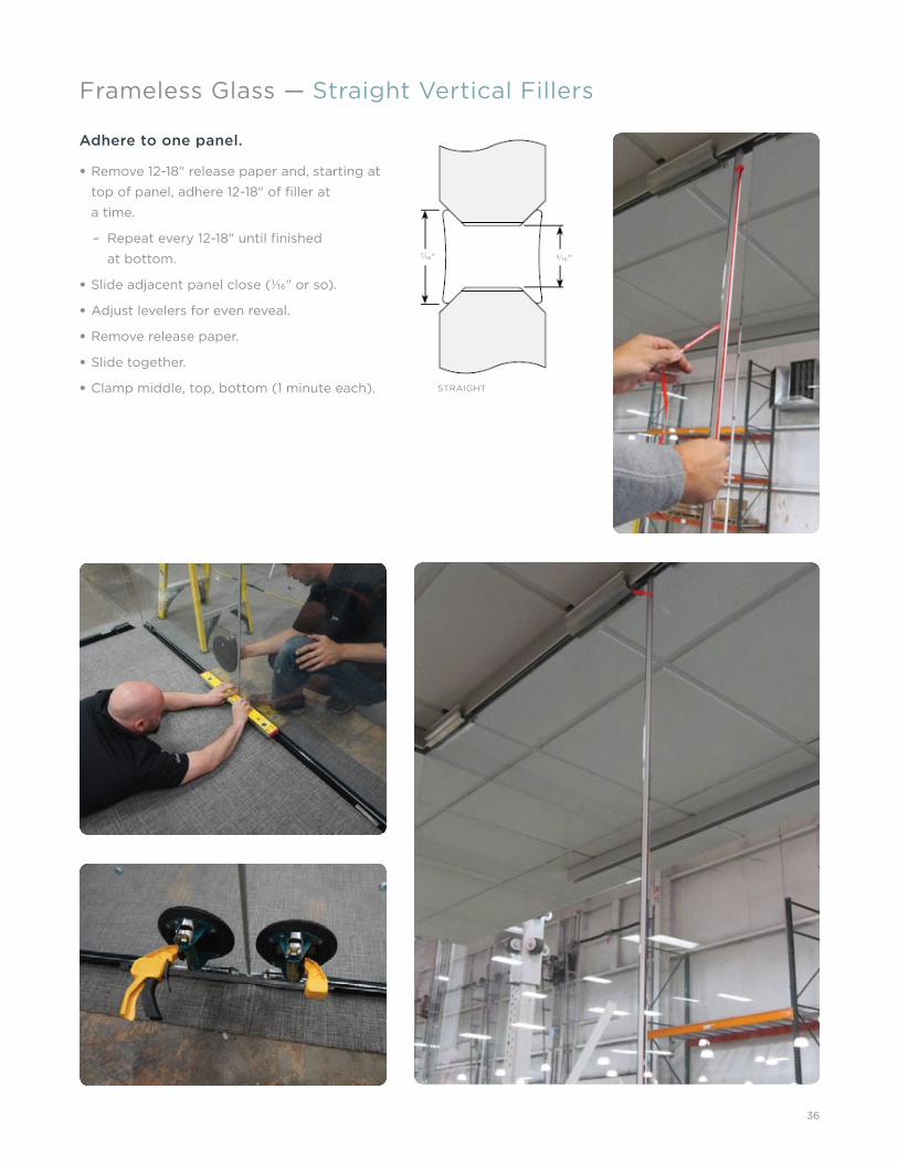
Frameless Glass — Straight Vertical Fillers
Adhere to one panel.
• Remove 12-18" release paper and, starting at
top of panel, adhere 12-18" of fi ller at
a time.
– Repeat every 12-18" until fi nished
at bottom.
• Slide adjacent panel close (1⁄16" or so).
• Adjust levelers for even reveal.
• Remove release paper.
• Slide together.
• Clamp middle, top, bottom (1 minute each). STRAIGHT
5⁄16"7⁄16"

37
• Align panels to align glass chambers.
• Remove 12-18" of release paper.
• Start at top while pushing in or out on glass
to align glass and fi ller adhere 12-18" at
a time.
• Repeat every 12-18" until fi nished
at bottom.
Frameless Glass — Two-Way Vertical Fillers
TWO-WAY
7⁄16"
7⁄16"

38
• Remove 12-18" release paper from the spine
side of the fi ller.
• Starting at top of panel adhere 12-18" of fi ller
to spine of the T only.
• Repeat every 12-18" until fi nished at bottom.
• Peel 2-3" tails on the remaining strips of
release paper.
• Slide panels close together (1⁄16" or so).
• Ensure panels are level/plumb.
• Adjust to make consistent reveals.
• Remove release paper.
• Slide together.
• Clamp middle, top, bottom (1 minute each).
Frameless Glass — Three-Way Vertical Fillers
THREE-WAY5⁄16"
7⁄16"
½"

39
• Repeat steps outlined on previous
page for three-way vertical fi llers.
• Align fourth panel close to fi ller.
• Adjust to make consistent reveal.
• Remove release paper.
• Slide together.
Frameless Glass — Four-Way Vertical Fillers
FOUR-WAY
5⁄16"

40
Similar to straight fi llers.
• Adhere to one edge with fi ller face slightly
recessed of the glass face.
– Remove 12-18" release paper and starting
at top of panel adhere 12-18" of fi ller at
a time.
– Repeat every 12-18" until fi nished
at bottom.
• Slide adjacent panel close (1⁄16" or so).
• Adjust levelers for even reveal.
• Remove release paper.
• Slide together ensuring the fi ller is slightly
recessed from face of glass face.
Frameless Glass — 135-Degree Vertical Fillers

41
• Measure fl oor to top of ceiling trim.
• Cut length is fl oor to top of trim dimension.
• Mark cut dimension measuring from top
of adapter.
• Cut to length.
• Loosen fasteners using Torx T20 bit.
• Moisten rubber fi ns with glass cleaner
or similar.
• Install on edge of glass.
• Fasteners to be tightened once mating door
frame has been installed.
• Adapter will be tightened through the door
frame access holes behind the vertical trim
of the door frame.
Frameless Glass — Adapters
SWING DOOR FRAME TO FRAMELESS ADAPTER
SLIDING DOOR FRAME / POST / SOLID WALL TO FRAMELESS ADAPTER

42
Frameless Glass — Adapters

43
Frameless Glass — Base Trim
• Base trim engages fl oor channel.
• Measure over from seam or door frame.
• Corners are factory mitered.
• Always align trim seams with vertical fi llers.
STANDARD BASE TRIM
INSIDE CORNER TOP VIEW
OUTSIDECORNER TOP VIEW
LOW-PROFILE BASE TRIM
44
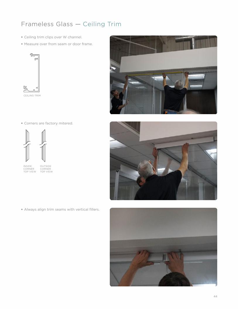
Frameless Glass — Ceiling Trim
• Ceiling trim clips over W channel.
• Measure over from seam or door frame.
• Corners are factory mitered.
• Always align trim seams with vertical fi llers.
CEILING TRIM
INSIDE CORNER TOP VIEW
OUTSIDECORNER TOP VIEW

45
Frameless Glass — Trim Keys
Two types used on both ceiling and base trims
for better trim alignment:
• Straight
Trim keys are utilized to ensure alignment at
straight and corner seams for both base and
ceiling trim.
Two trim keys are used at each trim seam
(inside and outside).
• Corner
STRAIGHT TRIM KEY
STRAIGHT TRIM KEY
CORNER TRIM KEY

46
Multiple privacy panel heights.
• All install from the bottom up.
Multiple tile options:
• Privacy rail shape varies based upon rail
and/or tile type:
– Full height base rail
– Bottom rail
– Middle rail
– Marker board rail
– Top rail
• All install using the same process.
Frameless Glass — Rail-Mounted Privacy
EXAMPLE OF INTEGRATED RAIL WITH WORKSURFACE AND HANGING SHELF

47
Frameless Glass — Rail-Mounted Privacy - Rail Installation
• Insert ⅜" bolt through washer.
• Insert bolt/washer through privacy rail.
• Place grommet into perforation in glass.
• Insert bolt/washer through rail through
grommet/glass perforation.
• Place grommet over bolt into glass
perforation on other side of panel.
• Place privacy rail over bolt and grommet.
• Install washer then nut over bolt, do
not tighten.
• Repeat for remaining attachment points in
privacy rail.
• Repeat process for required number of
privacy rails.
RAIL AND TRIP KIT WITHOUT TILES

48
Tiles install from bottom up.
Fabric/veneer/single height marker board:
• Bottom tile clips slide over fl ange on
privacy rail.
• Raise upper rail.
• Lean tile into upper rail.
• Lower upper rail ensuring fl ange engages
tile clips. Ensure ends of tiles and rails are
aligned prior to tightening bolts.
• Tighten bolt/nut.
Frameless Glass — Rail-Mounted Privacy - Tile Installation
EXAMPLE OF TWO-PANEL MODULE (TRIPLE TO THE BASE)
EXAMPLE OF THREE-PANEL MODULE (TRIPLE TO THE BASE)

49
Frameless Glass — Rail-Mounted Privacy - End Trim Installation
Uses corner trim alignment clips.

50
DISTRACTIONMARKER
SINGLE-SIDEDBUTTON
DOUBLE-SIDEDBUTTON
Button-mounted tiles/distraction markers
attach using factory perforations in the glass.
• Ensure perforated panels are installed
per plan.
• Installation is a two person process, one on
each side of glass.
• Three types:
– Distraction marker
– Provides visual cue to the glass.
– Does not support privacy tiles.
– Single sided standoff
– Allows installation of privacy tiles to one
side of the panel only.
– Double sided standoff
– Allows installation of privacy tiles to
both sides of panel.
Frameless Glass — Button-Mounted Privacy

51
Distraction marker installation:
• Insert grommet into glass perforation.
• Insert stud on distraction marker through
installed grommet and glass perforation.
• Insert grommet onto stud and into glass on
other side of panel.
• Thread distraction marker onto protruding
stud and tighten.
Standoff installation:
• Insert grommet into glass perforation.
• Insert stud on tile standoff through installed
grommet and perforation.
• Insert grommet on other side of glass.
• Thread tile standoff onto protruding stud
and tighten.
Frameless Glass — Button-Mounted Privacy - Mounting

52
Frameless Glass — Button-Mounted Privacy - Tile Installation
• Install studs into standoff s.
• Place grommet over stud.
• For ⅜" thick tiles use ⅛" nylon spacer.
• Align holes in tile with studs.
• Place tile onto studs.
• Insert grommets onto studs.
• Install distraction marker cap onto stud and tighten.
40" , 42" , 48" WIDTH TILES STANDARD
48.000
28¾ (28.75) +/- ¾'' (.75'')
1''

53
Framed Glass/Solid Wall — Standing Panels
• Lean panel under ceiling channel, aligning
panel with ceiling channel.
• Engage top rail of panel into ceiling channel.
• Stand panel up.

54
See Setting Panel Height Section (page 30)
for setting initial panel height.
• Set panel height and level initial panel
in run.
• Set up a laser level for a reference level line.
• Measure from the top of the panel tile (solid)
or top of glass horizontal (framed) down to
laser line.
• Record this dimension.
• Using same laser line adjust panels up or
down to the recorded dimension.
Framed Glass/Solid Wall — Leveling

55
Framed Glass/Solid Wall — Two-Way Posts
• Measure fl oor to top of panel tile (solid), or
top of glass horizontal (framed).
• Cut material from bottom of post.
– Top of post is notched.
• Cut length is fl oor to top of panel
tile (solid), or top of glass horizontal
(framed) dimension.
ZIPPERS
TWO-WAY POST
SOLID PANEL
SOLID PANEL
working_with_solid_7

56
Framed Glass/Solid Wall — Three-Way Posts
• Measure fl oor to top of panel tile (solid), or
top of glass horizontal (framed).
• Cut material from bottom of post.
– Top of post is notched.
• Cut length is fl oor to top of panel tile
(solid), or top of glass horizontal (framed)
dimension.

57
Framed Glass/Solid Wall — Zippers
• Flex notched end of zipper.
• Align top notched end of zipper with top
of panel and press zipper in.
• Trim excess zipper fl ush with top of
panel, fl ipper door or overhead, or fl oor
as appropriate.
• Where a zipper is used to attach other than
a panel, (i.e., post) a notch fi ller is needed.

58
Framed Glass/Solid Wall — Base Trim
• Measure to determine needed trim length.
• Cut trim to length. Any seam should
align with a zipper.
• Snap x-mas trees onto top fl ange of trim.
• Pull fl ipper doors out to ease installation
of trim.
• Slide fl at plastic over fl ipper door to capture
fl ipper door between plastic and trim.
• Rotate and pull trim up and insert x-mas tree
into slot in base rail assembly.
• Press trim to engage x-mas tree.

59
Doors — Sliding Door - “W” Channel
• The two shorter "W" channels need to be
replaced with a longer "W" channel on panels
where sliding door track will attach prior to
installation.
• Measure outside to outside of two shorter
channels.
– This dimension is the cut dimension for the
longer channel.
• Cut the longer channel to the above
dimension.
• Remove both shorter channels.
• Fill space between attachment blocks with
white plastic spacer.
• Attachment holes in longer channels will need
to be fi eld drilled.
• Ensure channel is fully seated prior to
installing attachment screws.
• Install panel.
REPLACE SHORTERCHANNELS WITH LONGER CHANNEL
FRAMELESS WALLSLIDING DOORHARDWARE. THESEPARTS ATTACH TO THE ADJACENTWALL
ADD STABILIZERSDIRECTLY ON GLASS WALL

60
• Measure fl oor to top of ceiling trim
(frameless) for each side of door opening.
• Cut verticals.
• Install zinc castings into door header where
required. Not needed on sliding frameless
glass door frame.
• Assemble verticals to door header.
• Install quantity two - ¼"-20 x 1-¼" - ⅜" hex
drive bolts per side.
Doors — Sliding Door - Frame Assembly

61
Assemble door frame per door frame instructions.
• Install door frame into door opening similar
to standing a panel.
• Lean door frame under ceiling channel,
aligning door frame with ceiling channel.
• Engage top rail of door frame into ceiling
channel.
• Stand door frame up.
• Install door frame ensuring the correct door
guide is installed under door frame.
Doors — Sliding Door - Frame Installation

62
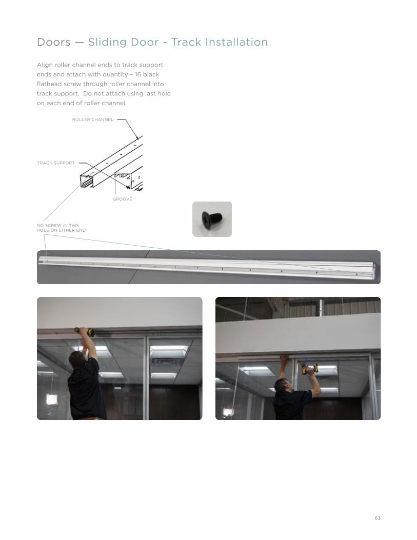
Doors — Sliding Door - Track Installation
THIS TRIM MUST BE INSTALLED PRIOR TO ATTACHING TRACK SUPPORT
THREADED INSERTS FOR MACHINE SCREWS
ATTACH DOOR TRACK SUPPORT USING QUANTITY THREE – ¼-20 PANHEAD MACHINE SCREWS
ATTACH DOOR TRACK SUPPORT USING QUANTITY THREE – ¼-20 PANHEAD MACHINE SCREWS
Level track support and attach using:
• Frameless: quantity fi ve black self drilling screws
• Framed: quantity fi ve black screws
63
Doors — Sliding Door - Track Installation
NO SCREW IN THIS HOLE ON EITHER END
GROOVE
ROLLER CHANNEL
TRACK SUPPORT
Align roller channel ends to track support
ends and attach with quantity – 16 black
fl athead screw through roller channel into
track support. Do not attach using last hole
on each end of roller channel.

64
Doors — Sliding Door - Trolley Installation
Insert trolleys into roller channel as shown: Install door track end covers using long silver screws.
Tighten stop blocks. These will be adjusted after the
doors are hung to align the door edges with ends of
roller track.

65
Doors — Sliding Door - Header Assembly
• Determine face and back of door using door
handle holes.
• Install the two clear U shaped gaskets.
• From back side of door insert bolt through
thick extrusion, through bushing, through
glass, through second bushing then ⅛"
spacer and thread loosely into square nut.
• Repeat for other side.
• Slide thin extrusion on from end with square
nut sliding inside groove in extrusion.
– Note orientation of extrusions.
• Align ends of extrusions and tighten bolt
using hex driver.
NOTE ORIENTATION OF EXTRUSIONS AND ALIGNMENT WITH EDGE OF GLASS.
• Slide thin extrusion on from end
with square nut sliding inside
groove in extrusion.
• Align ends of extrusions and
align fl ush with edge of glass
and tighten using hex driver.

66
Doors — Sliding Door - Header Assembly
• Slide trolley hanger into slot on top
extrusion.
• Note orientation of latches on trolley
hangers. Pointed end of latch goes toward
center of door and motion of latch allows
the latch to be pushed with a screwdriver
from face of door to disengage trolley from
hanger. With correct orientation only.
• Secure with quantity 4 – silver fl at head
screws.
• Repeat for other hanger.
FACE OF DOOR

67
Install door header end caps on each end using
quantity two small black screws on each end.
DOOR HEADER END CAPSDOOR TRACK END CAPS
Install door leaf:
• Align door under door track with
trolleys installed.
• Raise door and engage pins on trolleys
to trolley hangers on door leaf.
• Install door guide retainer and install
fastener.
Doors — Sliding Door - Header Assembly and Door Leaf

68
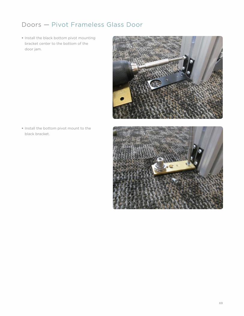
Doors — Pivot Frameless Glass Door
Install top pivot housing with the “long side”
toward the center of the door header.
DOOR HORIZONTAL
PIVOT PLATEPLATE SCREWS
HORIZONTAL TRIM
LEVELING STUD
69
• Install the black bottom pivot mounting
bracket center to the bottom of the
door jam.
Doors — Pivot Frameless Glass Door
• Install the bottom pivot mount to the
black bracket.
70
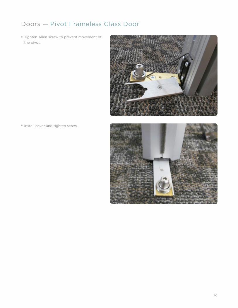
Doors — Pivot Frameless Glass Door
• Tighten Allen screw to prevent movement of
the pivot.
• Install cover and tighten screw.

71
• Installing the pivot hardware (patches).
Doors — Pivot Frameless Glass Door
• Install spacer provided in pre-drilled hole.

72
Doors — Pivot Frameless Glass Door
Line up left and right side of patch and fasten
together with the screws provided.

73
Doors — Pivot Frameless Glass Door
Install pivot mount housing as shown.
Bottom pivot mount shown here.
Top pivot mount shown here.
74
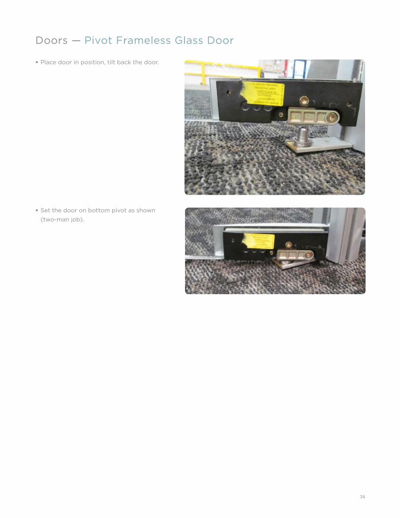
Doors — Pivot Frameless Glass Door
• Place door in position, tilt back the door.
• Set the door on bottom pivot as shown
(two-man job).

75
Doors — Pivot Frameless Glass Door
• Tilt door up in to top pivot position insert
top pivot housing secure to top patch with
Allen bolts provided.
• Install aluminum cover plates on both top
and bottom patches.

76
Doors — Hardware
77
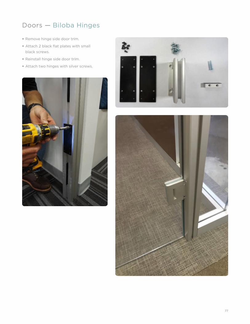
Doors — Biloba Hinges
• Remove hinge side door trim.
• Attach 2 black fl at plates with small
black screws.
• Reinstall hinge side door trim.
• Attach two hinges with silver screws.

78
Doors — Biloba Hinges
• Remove door retainer plate from hinge.
• Replace plastic gaskets with thinner gaskets
for ½" glass.
• Hang door.
• Reinstall retainer plates adjust door to
opening and tighten.
• Optional door stop may be installed to limit
door travel to 90 degrees.
– Holes are fi eld drilled.
– Install with quantity two - 1¼" silver fl at
head screws.
• Door hinge speed adjustment:
– Door speed may be adjusted by opening
adjustment valve.
– Depending upon hinge installation valve
may be on top or bottom of hinge.
Adjustment valve
Retainer plate

79
• Pull info from installation drawings.
• One in-feed per electrical run/side of panel.
• Lay out connected in-feed, receptacles, and/
or jumpers per plan.
• Base covers to be cut to fi ller-to-fi ller width.
• Install receptacles into base cover:
– Remove gasket.
– Replace clip with clips shipped with base
cover.
– Tab goes to bottom.
– Insert tab into slot in base cover.
– Align receptacle with base cover cutout.
– Snap receptacle into place.
– Install base cover on panel.
• Cut in-feed relief.
– In-feed to connect to building power
outside of panel, can attach via:
– Floor
– Wall
– Power pole
– For fl oor/wall connections:
– Cut notch to provide relief for in-feed.
– For power pole connections:
– In-feed to run through power pole for
connection in ceiling.
Miscellaneous — Electrical
80
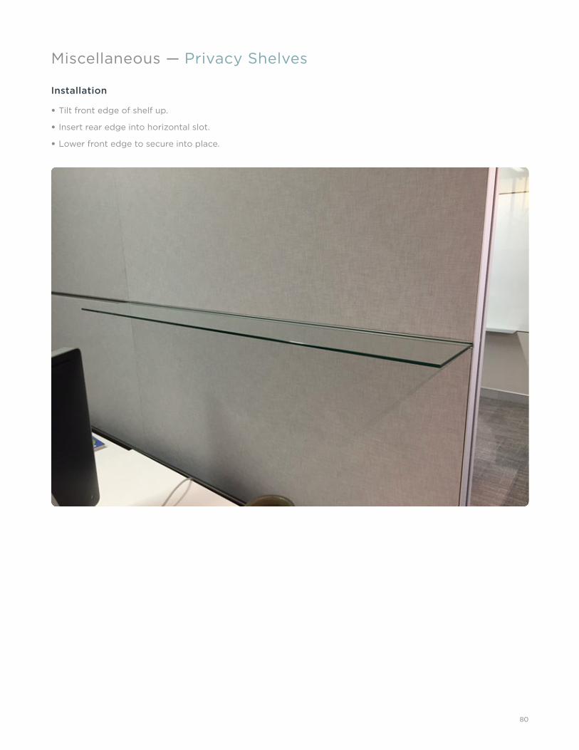
Miscellaneous — Privacy Shelves
Installation
• Tilt front edge of shelf up.
• Insert rear edge into horizontal slot.
• Lower front edge to secure into place.

81
Miscellaneous — Horizontal Brackets
Installation
• Insert machine screws through bracket.
• Thread machine screw into Z nut.
• Insert Z nut into panel horizontal
mounting rail.
• Slide to desired location(s).
• Tighten machine screws.
• Install worksurface.
HORIZONTAL HANGING
OVERHEAD BRACKET
HORIZONTAL HANGING
WORK SURFACEBRACKET
HORIZONTAL HANGING WALL, S16
WORKSURFACE BRACKET

82
Miscellaneous — Vertical Brackets
• Prior to installing zipper, install slot adapters
and seals at appropriate height.
• Install zippers, cutting to fi t around slot
adapter.
• Install bracket.
• Hang storage unit on storage bracket.
working_with_solid_1
HANGING ADAPTERS ARE REQUIRED FOR HANGING SYSTEMS COMPONENTS ON BEYOND WALLS
HANGING BRACKET ACCESSORY BRACKET
ZIPPER
SEE DETAIL D
DETAIL D
ADAPTER SEAL
SLOT ADAPTER FROM BEYONDTO MOUNTING BRACKETSTORAGE ANDMOUNTING BRACKET

83
Miscellaneous — Stacking
• Remove top fasteners in frame.
• Insert bayonet brackets into top of frame.
• Replace fasteners.

84
Miscellaneous — Care and Maintenance Instructions
Following are suggested methods for safe and eff ective cleaning and maintenance of Beyond’s wall products, including glass panels, solid panels and extrusions.
NOTE: It is highly recommended to clean Beyond walls at least once per year. In coastal areas where the finish is exposed to salt spray or in areas containing heavy industrial pollutants, Beyond walls should be cleaned as part of a regular, ongoing maintenance program. For best care, avoid extreme temperatures and humidity. Maintain temperatures between 60 and 80 degrees Fahrenheit and humidity levels between 30 and 50 percent.
GLASS SURFACESBeyond glass wall surfaces are very easy to maintain. Unless otherwise instructed by a Beyond Field Service Engineer, it is recommended to clean with warm water and a lint-free cloth (terry cloth). Conventional, non-abrasive glass cleaners may also be used with a lint-free cloth. All strongly alkaline caustic solutions as well as acids, especially hydrofl uoric acid, and cleaners containing fl uorides are unsuitable. Cleaning should begin with wetting the glass surface with clean water or a mild soap solution to loosen dirt. Using a neutral, non-abrasive commercial window washing solution, uniformly apply the solution to the glass surface with a brush, sponge, or other non-abrasive applicator. Immediately following the application of the cleaning solution, use a squeegee or lint-free cloth towel to remove all of the cleaning solution from the glass. Care should be taken to ensure that no abrasive particles are trapped between the glass and the cleaning materials. All water and cleaning solution residue should be dried immediately from gaskets, sealants, and frames to avoid the potential deterioration of these materials. It is strongly recommended to clean a small glass area or one window at a time, then stop and examine the surface for any undesirable impact to the glass.
SOLID PANELS
Vertical Surface Fabric
Remove as much soil or staining material as possible by carefully vacuuming, brushing or scraping with a dull instrument. Clean with shampoo, foam or dry cleaning solvents without saturating with liquid. Pile fabrics may require brushing to restore appearance.
Water-Borne Soil
Follow these directions for removing water-borne, non-greasy soil or stains (such as coff ee, milk, soft drinks, fruit juices, washable ink, etc.):
Gently apply a water-based cleaner (specifi cally made for cleaning fabric) to the soiled area using a clean cloth or sponge. Suitable cleaners include Bissell® Upholstery Shampoo, Woolite® Upholstery Shampoo, or Guardsman Fabri-Kleen®.
Work the cleaner into a lather or foam, if possible, to minimize soaking the fabric. With light brushing motions, apply from outside the soiled area toward the center to prevent rings.
Allow fabric to dry completely, and then vacuum thoroughly.
Oil-Borne Soil
Follow these directions for removing oil-borne soil or stains (such as salad dressing, grease, lipstick, ball-point ink, etc.):
Gently apply a dry-cleaning fl uid to the soiled area using a dampened cloth or soft-bristle brush.
With quick, light brush strokes, apply from outside the soiled area toward the center to prevent rings. Avoid soaking the fabric.
Gently blot with a clean, absorbent cloth to soak up and remove dampened soil.
Allow fabric to dry completely, and then vacuum thoroughly.
Large Areas
When large fabric areas must be cleaned, such as complete panels, it is recommended that you employ a professional cleaning fi rm that uses a dry-foam upholstery shampoo and an immediate wet pick-up vacuum system. Do not steam clean or use other methods that soak or heat the fabric.
Laminate and Metal
Wipe with a damp cloth to remove general soiling and water-borne stains. A hard-surface all-purpose cleaner (such as Formula 409, Fantastic, Top Job, Mr. Clean, etc.) may also be used. Oil-borne stains may require an application of dry-cleaning fl uid. Fill scratches in laminate surfaces with a coordinating oak, walnut, or mahogany putty stick (available at paint supply/hardware stores).
Wood
Use a cleaner or fl ax soap formulated especially for wood furniture. Dilute according to the manufacturer’s directions. Dampen (do not saturate) a soft cloth with the diluted cleaner and wipe surface in direction of the wood grain to remove dirt and fi ngerprints. Wipe clean with a soft, dry cloth. Do not use cleaners containing oils or ammonia on wood surfaces.

85
Miscellaneous — Care and Maintenance Instructions
EXTRUSIONS
Powdercoat Paint
Clean using mild soap solutions, such as products that are safe for use with bare hands (avoid use of strong acid or alkali cleaners, as they may damage the fi nish). Solvents no stronger than mineral spirits or denatured alcohol may be used to remove grease, sealants or other materials. Rinse the surface thoroughly with clean water and dry with a soft cloth. Do not use abrasive cleaners or materials, such as steel wool or abrasive brushes, which may harm the surface. Never mix cleaners or cleaners and solvents as the resultant mixture can cause harmful or even dangerous results.
Anodized Aluminum
Clean using mild soap solutions, such as products that are safe for use with bare hands (avoid the use of strong acid or alkali cleaners). Apply solution with a soft cloth, sponge or brush. Severely soiled anodized surfaces may be cleaned more aggressively than painted surfaces, such as with a mildly abrasive scrubbing pad. Use the pad to remove the mark, then clean the surface using the mild soap solution. Rinse the surface thoroughly with clean water and dry with a soft cloth.
Veneer Wrap
Do not use furniture polish. Instead, clean using mild soap solutions, such as products safe for use with bare hands (avoid the use of strong acid or alkali cleaners), to retain the original beauty of wood. Apply the solution with a soft cloth, sponge or brush. Rinse thoroughly with clean water and dry with a soft cloth. Always wipe the surface in the direction of the wood grain.
FIELD REPAIRS OF MINOR DAMAGE Some damage will inevitably occur and touch-up work will be required during or after installation. The good news is that minor scratches and rub marks on both painted and anodized surfaces can be easily repaired. Large dents or scratches will likely require replacement. A sample of the piece must be sent to Allsteel to get the best match.
Powdercoat Paint
Minor surface damage can be sanded with excellent results. For major scratches or gouges, use a relatively course grit paper to remove the damage, and then use progressively fi ner paper to remove the sanding marks, fi nishing with a 180 to 220 grit paper. Touchup paint is supplied with each installation. It comes in small aerosol cans or bottles with a built-in brush for easy application. It should be applied very sparingly, as it is intended to cover small blemishes or exposed ends on fabricated parts. It is not intended for use on large areas of more than a few square inches. The color will closely match the factory-applied painted fi nish; however, the fi nish is not as hard nor will it have the same performance as the baked-on fi nish.
To apply, clean the area to be touched up and wipe with denatured alcohol to remove any moisture or cleaning residue and apply per the instructions provided with the touchup kit.
Anodized Aluminum
Anodized material should not be sanded. Anodized surfaces are aluminum oxide, which is generally harder than the sandpaper. Most rub marks can simply be removed with a mild abrasive pad, such as Scotch-Brite®.
Veneer Wrap
Veneered extrusions with minor scratches can be mitigated with the supplied stain kit. For best results, engage a trained professional to complete this work.

©2016 Allsteel Inc. Allsteel and Beyond are registered trademarks. Indoor Advantage is a trademark of SCS Global Services. level is a registered trademark of BIFMA International.
Allsteel supports green initiatives in thecontract furniture industry as a memberof the U.S. Green Building Council. Beyondis an SCS Indoor Advantage™ Gold andlevel® 2 certifi ed product.
Allsteel Inc.Muscatine, Iowa 52761
allsteeloffi ce.com