Failure Mode and Effects Analysis System FMEA Design FMEA Process FMEA.
Best Practices for FMEA
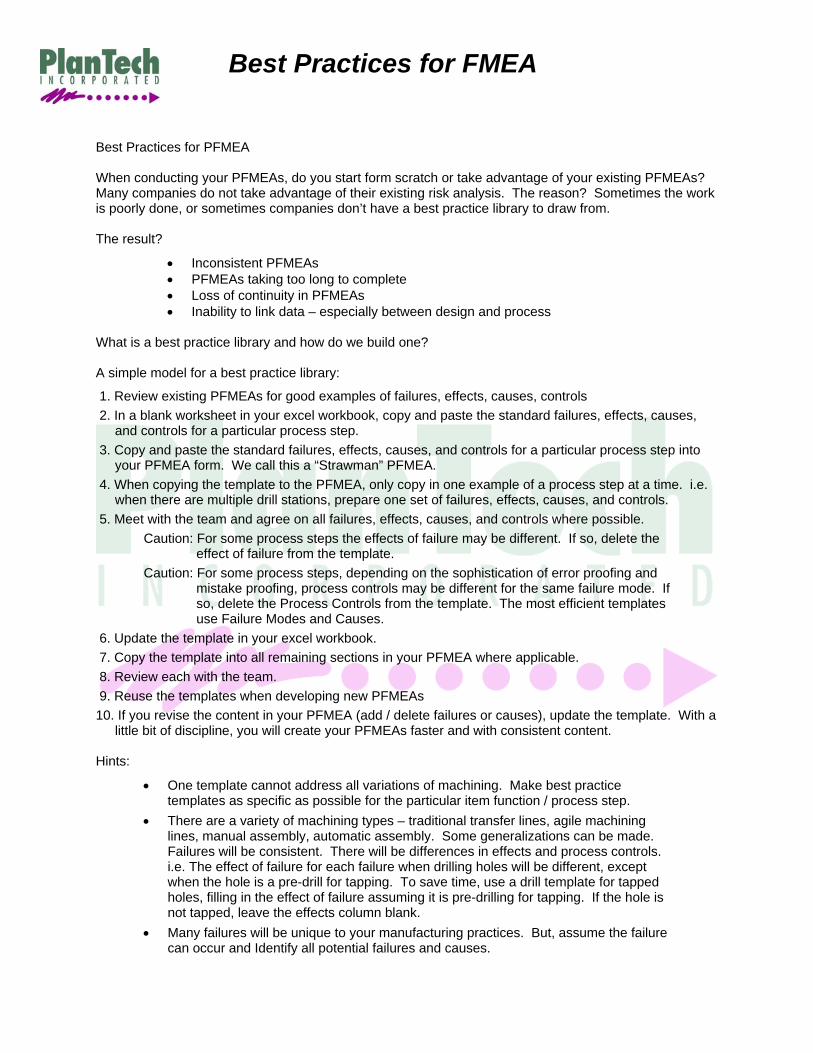
Best Practices for PFMEA When conducting your PFMEAs, do you start form scratch or take advantage of your existing PFMEAs? Many companies do not take advantage of their existing risk analysis. The reason? Sometimes the work is poorly done, or sometimes companies don’t have a best practice library to draw from. The result?
• Inconsistent PFMEAs • PFMEAs taking too long to complete • Loss of continuity in PFMEAs • Inability to link data – especially between design and process
What is a best practice library and how do we build one? A simple model for a best practice library:
1. Review existing PFMEAs for good examples of failures, effects, causes, controls 2. In a blank worksheet in your excel workbook, copy and paste the standard failures, effects, causes,
and controls for a particular process step. 3. Copy and paste the standard failures, effects, causes, and controls for a particular process step into
your PFMEA form. We call this a “Strawman” PFMEA. 4. When copying the template to the PFMEA, only copy in one example of a process step at a time. i.e.
when there are multiple drill stations, prepare one set of failures, effects, causes, and controls. 5. Meet with the team and agree on all failures, effects, causes, and controls where possible.
Caution: For some process steps the effects of failure may be different. If so, delete the effect of failure from the template.
Caution: For some process steps, depending on the sophistication of error proofing and mistake proofing, process controls may be different for the same failure mode. If so, delete the Process Controls from the template. The most efficient templates use Failure Modes and Causes.
6. Update the template in your excel workbook. 7. Copy the template into all remaining sections in your PFMEA where applicable. 8. Review each with the team. 9. Reuse the templates when developing new PFMEAs 10. If you revise the content in your PFMEA (add / delete failures or causes), update the template. With a
little bit of discipline, you will create your PFMEAs faster and with consistent content. Hints:
• One template cannot address all variations of machining. Make best practice templates as specific as possible for the particular item function / process step.
• There are a variety of machining types – traditional transfer lines, agile machining lines, manual assembly, automatic assembly. Some generalizations can be made. Failures will be consistent. There will be differences in effects and process controls. i.e. The effect of failure for each failure when drilling holes will be different, except when the hole is a pre-drill for tapping. To save time, use a drill template for tapped holes, filling in the effect of failure assuming it is pre-drilling for tapping. If the hole is not tapped, leave the effects column blank.
• Many failures will be unique to your manufacturing practices. But, assume the failure can occur and Identify all potential failures and causes.

Best Practices for FMEA
• Don’t worry about trying to identify every failure – you won’t. As you re-use your best practice templates you can add or delete.
• Identify failures, causes, and Process Controls for each manufacturing step. There may be variances in Process controls when budgets allow refined error proofing vs manual operations or operations applying minimal error proofing.
• When developing templates for PFMEAs, you will need one for manual operations and auto operations for a particular process step. i.e auto lubrication vs manual lubrication, auto torque vs manual torque.
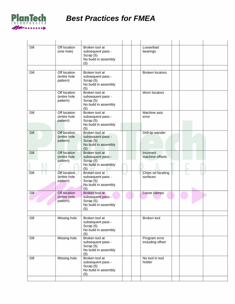
Example of Drill template with Effects of Failure Entered assuming a pre-drill for tap
Process Function /
Requirements
Potential Failure Mode
Potential Effect(s) of Failure
SEV Cla
ss Potential
Cause(s) / Mechanism(s)
of Failure
O C C
Current Process Controls
Prevention
Current Process Controls Detection
Dill Oversize Insufficient thread - inadequate joint strength - torque angle reject (5) Service reliability (7)
Incorrect tool
Dill Oversize Insufficient thread - inadequate joint strength - torque angle reject (5) Service reliability (7)
Damaged tool
Dill Oversize Insufficient thread - inadequate joint strength - torque angle reject (5) Service reliability (7)
Tool not seated in spindle
Dill Oversize Insufficient thread - inadequate joint strength - torque angle reject (5) Service reliability (7)
Part moves in fixture
Dill Oversize Insufficient thread - inadequate joint strength - torque angle reject (5) Service reliability (7)
Improper tool setup (wrong tool)
Dill Oversize Insufficient thread - inadequate joint strength - torque angle reject (5) Service reliability (7)
Insufficient thru spindle coolant volume

Best Practices for FMEA
Dill Oversize Insufficient thread - inadequate joint strength - torque angle reject (5) Service reliability (7)
Insufficient thru spindle coolant pressure
Dill Oversize Insufficient thread - inadequate joint strength - torque angle reject (5) Service reliability (7)
Drill tip wander
Dill Oversize Insufficient thread - inadequate joint strength - torque angle reject (5) Service reliability (7)
Coolant Cleanliness / Concentration
Dill Oversize Insufficient thread - inadequate joint strength - torque angle reject (5) Service reliability (7)
Worn / damaged tool holder
Dill Oversize Insufficient thread - inadequate joint strength - torque angle reject (5) Service reliability (7)
Build up on tool edge
Dill Oversize Insufficient thread - inadequate joint strength - torque angle reject (5) Service reliability (7)
Bad tool geometry/size
Dill Oversize Insufficient thread - inadequate joint strength - torque angle reject (5) Service reliability (7)
Wrong tool
Dill Undersize Broken tool at
subsequent oper - excessive % thread - torque angle reject (5)
Worn tool
Dill Undersize Broken tool at subsequent oper - excessive % thread - torque angle reject (5)
Improper tool setup (wrong tool)
Dill Undersize Broken tool at subsequent oper - excessive % thread - torque angle reject (5)
Damaged tool
Dill Undersize Broken tool at subsequent oper - excessive % thread - torque angle reject (5)
Bad tool geometry/size
Best Practices for FMEA
Dill Off location
(one hole) Broken tool at subsequent pass - Scrap (5) No build in assembly (5)
Loose/bad bearings
Dill Off location
(entire hole pattern)
Broken tool at subsequent pass - Scrap (5) No build in assembly (5)
Broken locators
Off location (entire hole pattern)
Broken tool at subsequent pass - Scrap (5) No build in assembly (5)
Worn locators
Dill Off location (entire hole pattern)
Broken tool at subsequent pass - Scrap (5) No build in assembly (5)
Machine axis error
Dill Off location (entire hole pattern)
Broken tool at subsequent pass - Scrap (5) No build in assembly (5)
Drill tip wander
Dill Off location (entire hole pattern)
Broken tool at subsequent pass - Scrap (5) No build in assembly (5)
Incorrect machine offsets
Dill Off location (entire hole pattern)
Broken tool at subsequent pass - Scrap (5) No build in assembly (5)
Chips on locating surfaces
Dill Off location (entire hole pattern)
Broken tool at subsequent pass - Scrap (5) No build in assembly (5)
Loose clamps
Dill Missing hole Broken tool at
subsequent pass - Scrap (5) No build in assembly (5)
Broken tool
Dill Missing hole Broken tool at subsequent pass - Scrap (5) No build in assembly (5)
Program error including offset
Dill Missing hole Broken tool at subsequent pass - Scrap (5) No build in assembly (5)
No tool in tool holder
Best Practices for FMEA
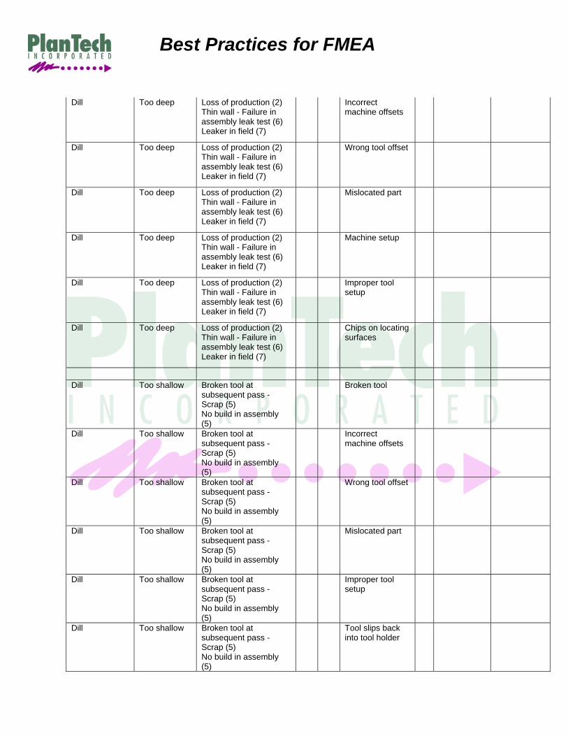
Dill Too deep Loss of production (2) Thin wall - Failure in assembly leak test (6) Leaker in field (7)
Incorrect machine offsets
Dill Too deep Loss of production (2) Thin wall - Failure in assembly leak test (6) Leaker in field (7)
Wrong tool offset
Dill Too deep Loss of production (2) Thin wall - Failure in assembly leak test (6) Leaker in field (7)
Mislocated part
Dill Too deep Loss of production (2) Thin wall - Failure in assembly leak test (6) Leaker in field (7)
Machine setup
Dill Too deep Loss of production (2) Thin wall - Failure in assembly leak test (6) Leaker in field (7)
Improper tool setup
Dill Too deep Loss of production (2) Thin wall - Failure in assembly leak test (6) Leaker in field (7)
Chips on locating surfaces
Dill Too shallow Broken tool at
subsequent pass - Scrap (5) No build in assembly (5)
Broken tool
Dill Too shallow Broken tool at subsequent pass - Scrap (5) No build in assembly (5)
Incorrect machine offsets
Dill Too shallow Broken tool at subsequent pass - Scrap (5) No build in assembly (5)
Wrong tool offset
Dill Too shallow Broken tool at subsequent pass - Scrap (5) No build in assembly (5)
Mislocated part
Dill Too shallow Broken tool at subsequent pass - Scrap (5) No build in assembly (5)
Improper tool setup
Dill Too shallow Broken tool at subsequent pass - Scrap (5) No build in assembly (5)
Tool slips back into tool holder

Best Practices for FMEA
Dill Too shallow Broken tool at subsequent pass - Scrap (5) No build in assembly (5)
Program interrupted during cycle
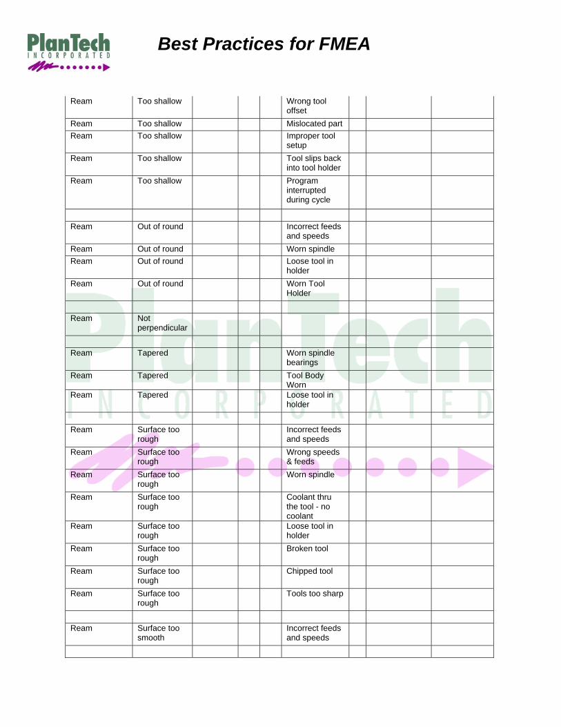
Example of Ream template - Failure Modes and Causes only
Process Function /
Requirements
Potential Failure Mode
Potential Effect(s)
of Failure
SEV Cla
ss
Potential Cause(s)
/ Mechanism(s)
of Failure
OCC
Current Process Controls
Prevention
Current Process Controls Detection
Ream Oversize Worn spindle bearing
Ream Oversize Damaged tool Ream Oversize Tool not seated
in spindle
Ream Oversize Part moves in
fixture
Ream Oversize Improper tool
setup (wrong tool)
Ream Oversize Insufficient thru
spindle coolant volume
Ream Oversize Insufficient thru
spindle coolant pressure
Ream Oversize Drill tip wander Ream Oversize Coolant
Cleanliness / Concentration
Ream Oversize Worn /
damaged tool holder
Ream Oversize Build up on tool
edge
Ream Oversize Bad tool
geometry/size
Ream Oversize Wrong tool Ream Undersize Worn tool Ream Undersize Improper tool
setup (wrong tool)
Ream Undersize Damaged tool

Best Practices for FMEA
Ream Bad tool geometry/size
Ream Off location
(one hole) Loose/bad
bearings
Ream Off location
(entire hole pattern)
Broken locators
Ream Off location
(entire hole pattern)
Worn locators
Ream Off location
(entire hole pattern)
Machine axis error
Ream Off location
(entire hole pattern)
Drill tip wander
Ream Off location
(entire hole pattern)
Incorrect machine offsets
Ream Off location
(entire hole pattern)
Chips on locating surfaces
Ream Off location
(entire hole pattern)
Loose clamps
Ream Missing hole Broken tool Ream Missing hole Program error
including offset
Ream Missing hole No tool in tool
holder
Ream Too deep Incorrect
machine offsets
Ream Too deep Wrong tool
offset
Ream Too deep Mislocated part Ream Too deep Machine setup Ream Too deep Improper tool
setup
Ream Too deep Chips on
locating surfaces
Ream Too shallow Broken tool Ream Too shallow Incorrect
machine offsets
Best Practices for FMEA
Ream Too shallow Wrong tool offset
Ream Too shallow Mislocated part Ream Too shallow Improper tool
setup
Ream Too shallow Tool slips back
into tool holder
Ream Too shallow Program
interrupted during cycle
Ream Out of round Incorrect feeds
and speeds
Ream Out of round Worn spindle Ream Out of round Loose tool in
holder
Ream Out of round Worn Tool
Holder
Ream Not
perpendicular
Ream Tapered Worn spindle
bearings
Ream Tapered Tool Body
Worn
Ream Tapered Loose tool in
holder
Ream Surface too
rough Incorrect feeds
and speeds
Ream Surface too
rough Wrong speeds & feeds
Ream Surface too rough
Worn spindle
Ream Surface too rough
Coolant thru the tool - no coolant
Ream Surface too rough
Loose tool in holder
Ream Surface too rough
Broken tool
Ream Surface too rough
Chipped tool
Ream Surface too rough
Tools too sharp
Ream Surface too
smooth Incorrect feeds and speeds
Best Practices for FMEA
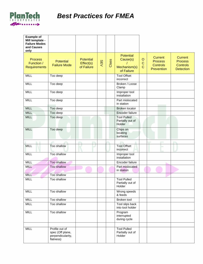
Example of Mill template - Failure Modes and Causes only
Process Function /
Requirements
Potential Failure Mode
Potential Effect(s) of Failure
SEV Cla
ss
Potential Cause(s)
/ Mechanism(s)
of Failure
O C C
Current Process Controls
Prevention
Current Process Controls Detection
MILL Too deep Tool Offset incorrect
MILL Too deep Broken / Loose Clamp
MILL Too deep Improper tool installation
MILL Too deep Part mislocated in station
MILL Too deep Broken locator MILL Too deep Encoder failure MILL Too deep Tool Pulled
Partially out of Holder
MILL Too deep Chips on
locating surfaces
MILL Too shallow Tool Offset
incorrect
MILL Too shallow Improper tool
installation
MILL Too shallow Encoder failure MILL Too shallow Part mislocated
in station
MILL Too shallow MILL Too shallow Tool Pulled
Partially out of Holder
MILL Too shallow Wrong speeds & feeds
MILL Too shallow Broken tool MILL Too shallow Tool slips back
into tool holder
MILL Too shallow Program
interrupted during cycle
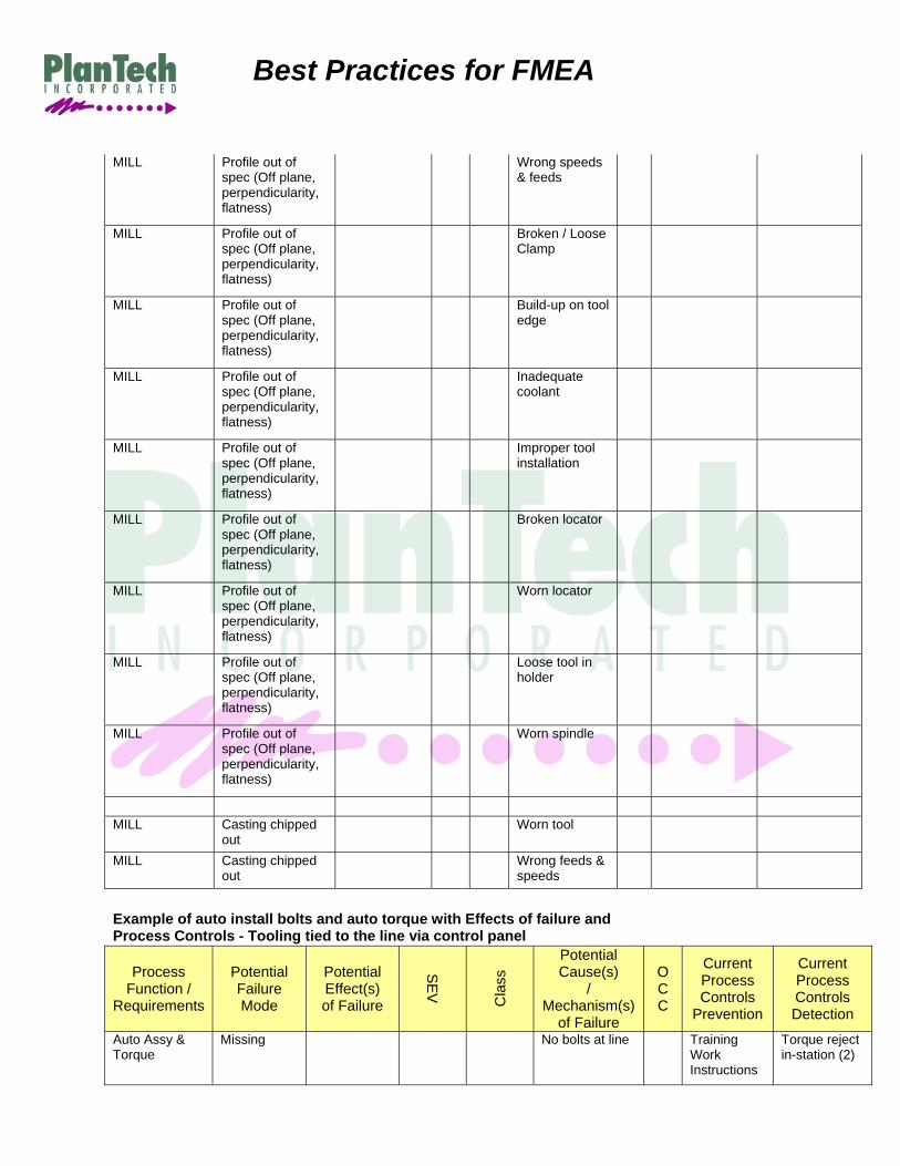
MILL Profile out of
spec (Off plane, perpendicularity, flatness)
Tool Pulled Partially out of Holder
Best Practices for FMEA
MILL Profile out of spec (Off plane, perpendicularity, flatness)
Wrong speeds & feeds
MILL Profile out of
spec (Off plane, perpendicularity, flatness)
Broken / Loose Clamp
MILL Profile out of
spec (Off plane, perpendicularity, flatness)
Build-up on tool edge
MILL Profile out of
spec (Off plane, perpendicularity, flatness)
Inadequate coolant
MILL Profile out of
spec (Off plane, perpendicularity, flatness)
Improper tool installation
MILL Profile out of
spec (Off plane, perpendicularity, flatness)
Broken locator
MILL Profile out of
spec (Off plane, perpendicularity, flatness)
Worn locator
MILL Profile out of
spec (Off plane, perpendicularity, flatness)
Loose tool in holder
MILL Profile out of
spec (Off plane, perpendicularity, flatness)
Worn spindle
MILL Casting chipped
out Worn tool
MILL Casting chipped
out Wrong feeds &
speeds
Example of auto install bolts and auto torque with Effects of failure and Process Controls - Tooling tied to the line via control panel
Process Function /
Requirements
Potential Failure Mode
Potential Effect(s) of Failure
SEV Cla
ss
Potential Cause(s)
/ Mechanism(s)
of Failure
O C C
Current Process Controls
Prevention
Current Process Controls Detection
Auto Assy & Torque
Missing No bolts at line Training Work Instructions
Torque reject in-station (2)

Best Practices for FMEA
Auto Assy & Torque
Missing Bolt feeder empty
Training Work Instructions
Torque reject in-station (2) Level detection on bolt feeder (2)
Auto Assy & Torque
Missing one bolt
Bolt feeder empty
Training Work Instructions
Torque reject in-station (2) Level detection on bolt feeder (2)
Auto Assy & Torque
wrong bolt Incorrect bolts put in bolt feeder
Training Work Instructions
Torque reject in-station (2) Vision system detects correct bolt (2)
Auto Assy & Torque
Cross threaded
Multi Spindle misaligned - bolt started on an angle
Training Work Instructions
Torque reject (5)
Auto Assy & Torque
Over torque Bolt failure -- rework in station - scrap (5) Premature bolt failure (7)
Tool out of calibration
Calibration program
Torque Audit (6)
Auto Assy & Torque
Over Torque Bolt failure -- rework in station - scrap (5) Premature bolt failure (7)
Operator fails to use correct tool
Training Work Instructions
Torque Audit (6)
Auto Assy & Torque
Over Torque Bolt failure -- rework in station - scrap (5) Premature bolt failure (7)
Wrench set to incorrect torue
Training Work Instructions
Torque Audit (6)
Auto Assy & Torque
Under torque Vibration, Shake - Loose in field - rattle Warranty (7)
Tool out of calibration
Calibration program
Torque Audit (6)
Best Practices for FMEA
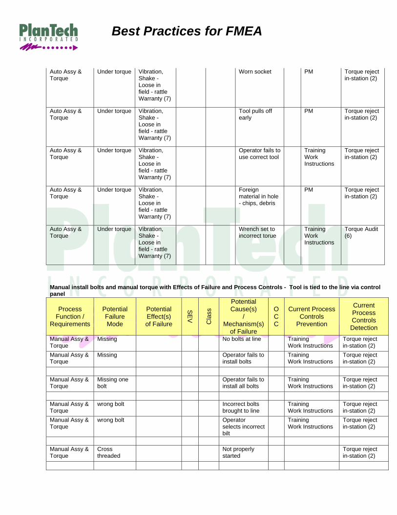
Auto Assy & Torque
Under torque Vibration, Shake - Loose in field - rattle Warranty (7)
Worn socket PM Torque reject in-station (2)
Auto Assy & Torque
Under torque Vibration, Shake - Loose in field - rattle Warranty (7)
Tool pulls off early
PM Torque reject in-station (2)
Auto Assy & Torque
Under torque Vibration, Shake - Loose in field - rattle Warranty (7)
Operator fails to use correct tool
Training Work Instructions
Torque reject in-station (2)
Auto Assy & Torque
Under torque Vibration, Shake - Loose in field - rattle Warranty (7)
Foreign material in hole - chips, debris
PM Torque reject in-station (2)
Auto Assy & Torque
Under torque Vibration, Shake - Loose in field - rattle Warranty (7)
Wrench set to incorrect torue
Training Work Instructions
Torque Audit (6)
Manual install bolts and manual torque with Effects of Failure and Process Controls - Tool is tied to the line via control panel
Process Function /
Requirements
Potential Failure Mode
Potential Effect(s) of Failure
SEV Cla
ss
Potential Cause(s)
/ Mechanism(s)
of Failure
O C C
Current Process Controls
Prevention
Current Process Controls Detection
Manual Assy & Torque
Missing No bolts at line Training Work Instructions
Torque reject in-station (2)
Manual Assy & Torque
Missing Operator fails to install bolts
Training Work Instructions
Torque reject in-station (2)
Manual Assy & Torque
Missing one bolt
Operator fails to install all bolts
Training Work Instructions
Torque reject in-station (2)
Manual Assy & Torque
wrong bolt Incorrect bolts brought to line
Training Work Instructions
Torque reject in-station (2)
Manual Assy & Torque
wrong bolt Operator selects incorrect bilt
Training Work Instructions
Torque reject in-station (2)
Manual Assy & Torque
Cross threaded
Not properly started
Torque reject in-station (2)
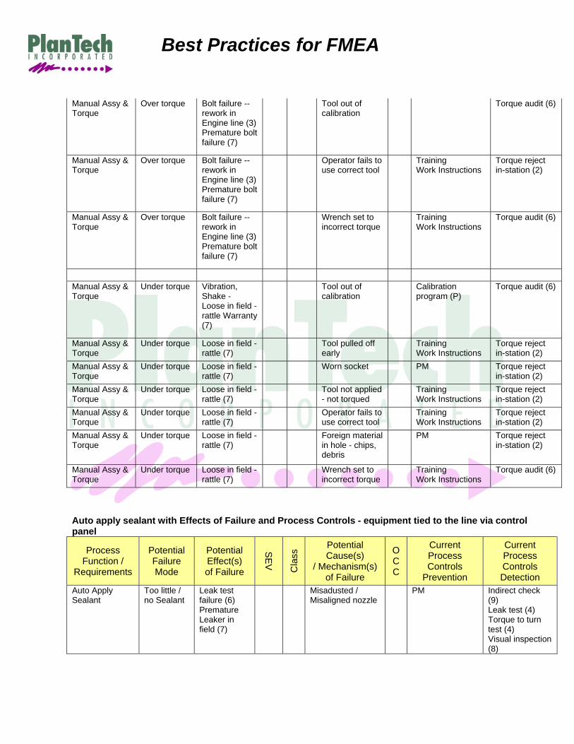
Best Practices for FMEA
Manual Assy & Torque
Over torque Bolt failure -- rework in Engine line (3)Premature bolt failure (7)
Tool out of calibration
Torque audit (6)
Manual Assy & Torque
Over torque Bolt failure -- rework in Engine line (3)Premature bolt failure (7)
Operator fails to use correct tool
Training Work Instructions
Torque reject in-station (2)
Manual Assy & Torque
Over torque Bolt failure -- rework in Engine line (3)Premature bolt failure (7)
Wrench set to incorrect torque
Training Work Instructions
Torque audit (6)
Manual Assy & Torque
Under torque Vibration, Shake - Loose in field - rattle Warranty (7)
Tool out of calibration
Calibration program (P)
Torque audit (6)
Manual Assy & Torque
Under torque Loose in field - rattle (7)
Tool pulled off early
Training Work Instructions
Torque reject in-station (2)
Manual Assy & Torque
Under torque Loose in field - rattle (7)
Worn socket PM Torque reject in-station (2)
Manual Assy & Torque
Under torque Loose in field - rattle (7)
Tool not applied - not torqued
Training Work Instructions
Torque reject in-station (2)
Manual Assy & Torque
Under torque Loose in field - rattle (7)
Operator fails to use correct tool
Training Work Instructions
Torque reject in-station (2)
Manual Assy & Torque
Under torque Loose in field - rattle (7)
Foreign material in hole - chips, debris
PM Torque reject in-station (2)
Manual Assy & Torque
Under torque Loose in field - rattle (7)
Wrench set to incorrect torque
Training Work Instructions
Torque audit (6)
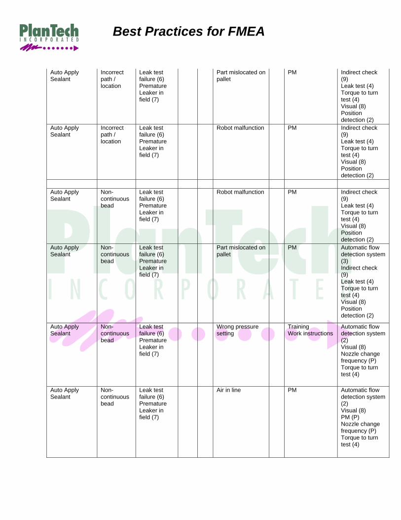
Auto apply sealant with Effects of Failure and Process Controls - equipment tied to the line via control panel
Process Function /
Requirements
Potential Failure Mode
Potential Effect(s) of Failure
SEV Cla
ss Potential
Cause(s) / Mechanism(s)
of Failure
OCC
Current Process Controls
Prevention
Current Process Controls Detection
Auto Apply Sealant
Too little / no Sealant
Leak test failure (6) Premature Leaker in field (7)
Misadusted / Misaligned nozzle
PM Indirect check (9) Leak test (4) Torque to turn test (4) Visual inspection (8)

Best Practices for FMEA
Auto Apply Sealant
Too little / no Sealant
Leak test failure (6) Premature Leaker in field (7)
Clogged nozzle
PM Automatic flow detection system (2) Indirect check (9) Leak test (4) Torque to turn test (4) Visual (8)
Auto Apply Sealant
Too little / no Sealant
Leak test failure (6) Premature Leaker in field (7)
Reservoir runs out of sealer
PM Automatic flow detection system (2) Indirect check (9) Leak test (4) Torque to turn test (4) Visual (8) Level indicator (3)
Auto Apply Sealant
Too little / no Sealant
Leak test failure (6) Premature Leaker in field (7)
Part mislocated on pallet
PM Indirect check (9) Leak test (4) Torque to turn test (4) Visual (8) Position detection (2)
Auto Apply Sealant
Too little / no Sealant
Leak test failure (6) Premature Leaker in field (7)
Wrong pressure setting
PM Automatic flow detection system (2) Indirect check (9) Leak test (4) Torque to turn test (4) Visual (8) Position detection (2)
Auto Apply Sealant
Too much Sealant
Material in bolt holes (3)Torque to turn failure (5)
Worn nozzle
PM Automatic flow detection system (2) Visual (8) Nozzle change frequency (P) Torque to turn test (4)
Auto Apply Sealant
Too much Sealant
Material in bolt holes (3)Torque to turn failure (5)
Wrong pressure setting
Training Work instructions
Automatic flow detection system (2) Visual (8) Nozzle change frequency (P) Torque to turn test (4)
Best Practices for FMEA
Auto Apply Sealant
Incorrect path / location
Leak test failure (6) Premature Leaker in field (7)
Part mislocated on pallet
PM Indirect check (9) Leak test (4) Torque to turn test (4) Visual (8) Position detection (2)
Auto Apply Sealant
Incorrect path / location
Leak test failure (6) Premature Leaker in field (7)
Robot malfunction
PM Indirect check (9) Leak test (4) Torque to turn test (4) Visual (8) Position detection (2)
Auto Apply Sealant
Non-continuous bead
Leak test failure (6) Premature Leaker in field (7)
Robot malfunction
PM Indirect check (9) Leak test (4) Torque to turn test (4) Visual (8) Position detection (2)
Auto Apply Sealant
Non-continuous bead
Leak test failure (6) Premature Leaker in field (7)
Part mislocated on pallet
PM Automatic flow detection system (3) Indirect check (9) Leak test (4) Torque to turn test (4) Visual (8) Position detection (2)
Auto Apply Sealant
Non-continuous bead
Leak test failure (6) Premature Leaker in field (7)
Wrong pressure setting
Training Work instructions
Automatic flow detection system (2) Visual (8) Nozzle change frequency (P) Torque to turn test (4)
Auto Apply Sealant
Non-continuous bead
Leak test failure (6) Premature Leaker in field (7)
Air in line
PM Automatic flow detection system (2) Visual (8) PM (P) Nozzle change frequency (P) Torque to turn test (4)

Best Practices for FMEA
Best Practices for DFMEA Although best practices work best with PFMEAs, you can apply the same practice to your DFMEAs. Companies that have a narrow product line can develop baseline DFMEAs to re-use for future designs. These work well when most systems have the same or similar functions. When the functions change, add or delete that section from the baseline DFMEA. Teams can also develop DFMEA templates by function. Be sure to address the standard design failures:
No Function Over Function Under Function Intermittent Function Premature Wear Unintended Function or Unintended Outcome.
Hints: Look for multiple examples for each failure type. Not all functions will address all six failure conditions
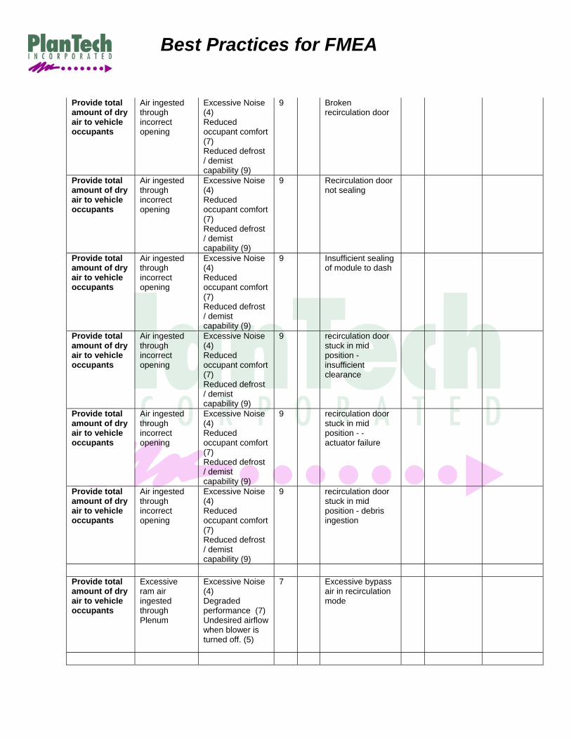
Air Flow System for a Vehicle
Item Function /
Requirements
Potential Failure Mode
Potential Effect(s) of Failure
SEV Cla
ss Potential
Cause(s) / Mechanism(s)
of Failure
O C C
Current Design
Controls Prevention
Current Design
Controls Detection
Provide total amount of dry air to vehicle occupants
No air flow No heating or cooling (8) Lose defrost capability (9)
9 Blower Motor failure
Provide total amount of dry air to vehicle occupants
No air flow No heating or cooling (8) Lose defrost capability (9)
9 Broken recirculation door
Provide total amount of dry air to vehicle occupants
No air flow No heating or cooling (8) Lose defrost capability (9)
9 Blower wheel failure (broken wheel)
Provide total amount of dry air to vehicle occupants
No air flow No heating or cooling (8) Lose defrost capability (9)
9 Motor stalled due to wheel damage
Provide total amount of dry air to vehicle occupants
No air flow No heating or cooling (8) Lose defrost capability (9)
9 Motor stalled due to debris ingestion
Provide total amount of dry air to vehicle occupants
No air flow No heating or cooling (8) Lose defrost capability (9)
9 Motor stalled due to water intrusion

Best Practices for FMEA
Provide total amount of dry air to vehicle occupants
No air flow No heating or cooling (8) Lose defrost capability (9)
9 Wheel rubs housing (insufficient clearance)
Provide total amount of dry air to vehicle occupants
No air flow No heating or cooling (8) Lose defrost capability (9)
9 Broken wheel due to imbalance
Provide total amount of dry air to vehicle occupants
No air flow No heating or cooling (8) Lose defrost capability (9)
9 Broken wheel due to insufficient cross section in wheel
Provide total amount of dry air to vehicle occupants
No air flow No heating or cooling (8) Lose defrost capability (9)
9 Low system voltage
Provide total amount of dry air to vehicle occupants
No air flow No heating or cooling (8) Lose defrost capability (9)
9 Module harness not connected to vehicle
Provide total amount of dry air to vehicle occupants
No air flow No heating or cooling (8) Lose defrost capability (9)
9 Blower speed control not connected Blower Motor
Provide total amount of dry air to vehicle occupants
No air flow No heating or cooling (8) Lose defrost capability (9)
9 Blower speed control failure
Provide total amount of dry air to vehicle occupants
Insufficient air flow
Reduced heating and cooling (7) Reduced defrost capability (9)
9 Evaporator icing
Provide total amount of dry air to vehicle occupants
Insufficient air flow
Reduced heating and cooling (7) Reduced defrost capability (9)
9 Blower wheel does not spin with blower motor (Low wheel to shaft press fit)
Provide total amount of dry air to vehicle occupants
Insufficient air flow
Reduced heating and cooling (7) Reduced defrost capability (9)
9 Improper motor cooling (Overheating)
Provide total amount of dry air to vehicle occupants
Insufficient air flow
Reduced heating and cooling (7) Reduced defrost capability (9)
9 Incorrect harness pin-outs
Provide total amount of dry air to vehicle occupants
Insufficient air flow
Reduced heating and cooling (7) Reduced defrost capability (9)
9 Blower Motor improperly sized (Excessive windings)

Best Practices for FMEA
Provide total amount of dry air to vehicle occupants
Insufficient air flow
Reduced heating and cooling (7) Reduced defrost capability (9)
9 Wheel rubs housing (insufficient clearance)
Provide total amount of dry air to vehicle occupants
Insufficient air flow
Reduced heating and cooling (7) Reduced defrost capability (9)
9 Excessive clearance between wheel and housing
Provide total amount of dry air to vehicle occupants
Insufficient air flow
Reduced heating and cooling (7) Reduced defrost capability (9)
9 Block due to debris
Provide total amount of dry air to vehicle occupants
Insufficient air flow
Reduced heating and cooling (7) Reduced defrost capability (9)
9 Excessive pressure drop in module (heat exchanger / air inlet)
Provide total amount of dry air to vehicle occupants
Insufficient air flow
Reduced heating and cooling (7) Reduced defrost capability (9)
9 Insufficient sealing of module to dash
Provide total amount of dry air to vehicle occupants
Insufficient air flow
Reduced heating and cooling (7) Reduced defrost capability (9)
9 Insufficient sealing of module case (tongue and groove)
Provide total amount of dry air to vehicle occupants
Insufficient air flow
Reduced heating and cooling (7) Reduced defrost capability (9)
9 Heater core fins bent inserting into Module (due to design tolerance stack up)
Provide total amount of dry air to vehicle occupants
Insufficient air flow
Reduced heating and cooling (7) Reduced defrost capability (9)
9 Improperly specified blower speed control
Provide total amount of dry air to vehicle occupants
Insufficient air flow
Reduced heating and cooling (7) Reduced defrost capability (9)
9 Blower Motor improperly sized (Excessive windings)
Provide total amount of dry air to vehicle occupants
Insufficient air flow
Reduced air flow - reduced heating and cooling (7) Reduced defrost capability (9)
9 Insufficient cross sectional area of plenum and cowl opening
Provide total amount of dry air to vehicle occupants
Insufficient air flow
Reduced air flow - reduced heating and cooling (7) Reduced defrost capability (9)
9 Insufficient cross sectional area of air inlet
Provide total amount of dry air to vehicle occupants
Insufficient air flow
Reduced air flow - reduced heating and cooling (7) Reduced defrost capability (9)
9 Improper sizing of recirculation inlet (too small)

Best Practices for FMEA
Provide total amount of dry air to vehicle occupants
Insufficient air flow
Reduced air flow - reduced heating and cooling (7) Reduced defrost capability (9)
9 Improper sizing of recirculation door (too small)
Provide total amount of dry air to vehicle occupants
Insufficient air flow
Reduced air flow - reduced heating and cooling (7) Reduced defrost capability (9)
9 Incorrect shape of recirculation door
Provide total amount of dry air to vehicle occupants
Insufficient air flow
Reduced air flow - reduced heating and cooling (7) Reduced defrost capability (9)
9 recirculation door stuck in mid position
Provide total amount of dry air to vehicle occupants
Excessive Air flow
Uncontrolled heating and cooling (7) Occcupant discomfort (7)
7 Blower Motor improperly sized (Excessive windings)
Provide total amount of dry air to vehicle occupants
Excessive Air flow
Uncontrolled heating and cooling (7) Occcupant discomfort (7)
7 Improper sizing of recirculation door (too small)
Provide total amount of dry air to vehicle occupants
Excessive Air flow
Uncontrolled heating and cooling (7) Occcupant discomfort (7)
7 Excessive cross sectional area of plenum and cowl opening
Provide total amount of dry air to vehicle occupants
Excessive Air flow
Uncontrolled heating and cooling (7) Occcupant discomfort (7)
7 Improperly specified blower speed control
Provide total amount of dry air to vehicle occupants
Intermittent air flow
No heating or cooling (8) Lose defrost capability (9)
9 Improperly sized resistors
Provide total amount of dry air to vehicle occupants
Intermittent air flow
No heating or cooling (8) Lose defrost capability (9)
9 Incorrect wire harness routings
Provide total amount of dry air to vehicle occupants
Intermittent air flow
No heating or cooling (8) Lose defrost capability (9)
9 Improperly specified wire gage
Best Practices for FMEA
Provide total amount of dry air to vehicle occupants
Air ingested through incorrect opening
Excessive Noise (4) Reduced occupant comfort (7) Reduced defrost / demist capability (9)
9 Broken recirculation door
Provide total amount of dry air to vehicle occupants
Air ingested through incorrect opening
Excessive Noise (4) Reduced occupant comfort (7) Reduced defrost / demist capability (9)
9 Recirculation door not sealing
Provide total amount of dry air to vehicle occupants
Air ingested through incorrect opening
Excessive Noise (4) Reduced occupant comfort (7) Reduced defrost / demist capability (9)
9 Insufficient sealing of module to dash
Provide total amount of dry air to vehicle occupants
Air ingested through incorrect opening
Excessive Noise (4) Reduced occupant comfort (7) Reduced defrost / demist capability (9)
9 recirculation door stuck in mid position - insufficient clearance
Provide total amount of dry air to vehicle occupants
Air ingested through incorrect opening
Excessive Noise (4) Reduced occupant comfort (7) Reduced defrost / demist capability (9)
9
recirculation door stuck in mid position - - actuator failure
Provide total amount of dry air to vehicle occupants
Air ingested through incorrect opening
Excessive Noise (4) Reduced occupant comfort (7) Reduced defrost / demist capability (9)
9
recirculation door stuck in mid position - debris ingestion
Provide total amount of dry air to vehicle occupants
Excessive ram air ingested through Plenum
Excessive Noise (4) Degraded performance (7)Undesired airflow when blower is turned off. (5)
7 Excessive bypass air in recirculation mode

Best Practices for FMEA
Provide total amount of dry air to vehicle occupants
Dirty / contaminated air in passenger compartment (ATC only)
Allergic reactions - customer dissatisfied (6) Unpleasant odor (6)
6 Incorrect shape of recirculation door
3
Provide total amount of dry air to vehicle occupants
Dirty / contaminated air in passenger compartment (ATC only)
Allergic reactions - customer dissatisfied (6) Unpleasant odor (6)
6 Improper sealing of air inlet to dash
2
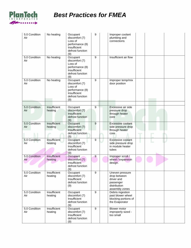
Heating System for a Vehicle
Item Function /
Requirements
Potential Failure Mode
Potential Effect(s) of Failure
SEV Cla
ss Potential
Cause(s) / Mechanism(s)
of Failure
O C C
Current Design
Controls Prevention
Current Design
Controls Detection
5.0 Condition Air
No heating Occupant discomfort (7) Loss of performance (8) Insufficient defrost function (9)
9 Improper heater core
5.0 Condition Air
No heating Occupant discomfort (7) Loss of performance (8) Insufficient defrost function (9)
9 Improper coolant plumbing and connections
5.0 Condition Air
No heating Occupant discomfort (7) Loss of performance (8) Insufficient defrost function (9)
9 Insufficient air flow
5.0 Condition Air
No heating Occupant discomfort (7) Loss of performance (8) Insufficient defrost function (9)
9 Improper temp/mix door position
5.0 Condition Air
No heating Occupant discomfort (7) Loss of performance (8) Insufficient defrost function (9)
9 Improper heater core
Best Practices for FMEA
5.0 Condition Air
No heating Occupant discomfort (7) Loss of performance (8) Insufficient defrost function (9)
9 Improper coolant plumbing and connections
5.0 Condition Air
No heating Occupant discomfort (7) Loss of performance (8) Insufficient defrost function (9)
9 Insufficient air flow
5.0 Condition Air
No heating Occupant discomfort (7) Loss of performance (8) Insufficient defrost function (9)
9 Improper temp/mix door position
5.0 Condition Air
Insufficient heating
Occupant discomfort (7) Insufficient defrost function (9)
9 Excessive air side pressure drop through heater core
5.0 Condition Air
Insufficient heating
Occupant discomfort (7) Insufficient defrost function (9)
9 Excessive coolant side pressure drop through heater core
5.0 Condition Air
Insufficient heating
Occupant discomfort (7) Insufficient defrost function (9)
9 Excessive coolant side pressure drop in module heater tubes
5.0 Condition Air
Insufficient heating
Occupant discomfort (7) Insufficient defrost function (9)
9 Improper scroll / wheel / expansion design.
5.0 Condition Air
Insufficient heating
Occupant discomfort (7) Insufficient defrost function (9)
9 Uneven pressure drop between driver and passenger distribution assembly zones
5.0 Condition Air
Insufficient heating
Occupant discomfort (7) Insufficient defrost function (9)
9 Debris ingestion past blower wheel blocking portions of the Evaporator
5.0 Condition Air
Insufficient heating
Occupant discomfort (7) Insufficient defrost function (9)
9 Blower motor improperly sized - too small

Best Practices for FMEA
5.0 Condition Air
Insufficient heating
Occupant discomfort (7) Insufficient defrost function (9)
9 Excessive air bypass in module due to insufficient cold door sealing
5.0 Condition Air
Insufficient heating
Occupant discomfort (7) Insufficient defrost function (9)
9 Evaporator sized too small
5.0 Condition Air
Insufficient heating
Occupant discomfort (7) Insufficient defrost function (9)
9 Improper Heater Core selection (UB vs UT)
5.0 Condition Air
Insufficient heating
Occupant discomfort (7) Insufficient defrost function (9)
9 Incorrect Heater Core fin density
5.0 Condition Air
Insufficient heating
Occupant discomfort (7) Insufficient defrost function (9)
9 Incorrect Heater Core location / orientation
5.0 Condition Air
Insufficient heating
Occupant discomfort (7) Insufficient defrost function (9)
9 Coolant leak at Heater tube to tank interface due to improper o-ring material
5.0 Condition Air
Insufficient heating
Occupant discomfort (7) Insufficient defrost function (9)
9 Coolant leak at Heater tube to tank interface due to improper o-ring size,
5.0 Condition Air
Insufficient heating
Occupant discomfort (7) Insufficient defrost function (9)
9 Coolant leak at Heater tube to tank interface due to end form sizing on tube (large or small)
5.0 Condition Air
Insufficient heating
Occupant discomfort (7) Insufficient defrost function (9)
9 Coolant leak at Heater tube to tank interface due to end form sizing on Heater Core Tower (large or small)
5.0 Condition Air
Insufficient heating
Occupant discomfort (7) Insufficient defrost function (9)
9 Coolant leak at Heater tube to tank interface due to Insufficient clip retention forces

Best Practices for FMEA
5.0 Condition Air
Insufficient heating
Occupant discomfort (7) Insufficient defrost function (9)
9 Design allows creation of coolant leaks due to mishandling of Heater Core assembly
5.0 Condition Air
Insufficient heating
Occupant discomfort (7) Insufficient defrost function (9)
9 Case leakage due to poor housing design (tongue and groove, parting lines with abrupt plane changes, uneven sealing surface)
5.0 Condition Air
Insufficient heating
Occupant discomfort (7) Insufficient defrost function (9)
9 Case leakage due to poor fit between Heater Core and housings
5.0 Condition Air
Insufficient heating
Occupant discomfort (7) Insufficient defrost function (9)
9 Case leakage due to improper Heater Core End Tank seal material
5.0 Condition Air
Insufficient heating
Occupant discomfort (7) Insufficient defrost function (9)
9 Case leakage due to improper Heater Core End Tank seal seal design - Seal height too short
5.0 Condition Air
Insufficient heating
Occupant discomfort (7) Insufficient defrost function (9)
9 Case leakage due to improper Heater Core End Tank seal seal design - Seal width not wide enough
5.0 Condition Air
Insufficient heating
Occupant discomfort (7) Insufficient defrost function (9)
9 Case leakage due to improper Heater Core End Tank seal seal design - Seal length not long enough
5.0 Condition Air
Insufficient heating
Occupant discomfort (7) Insufficient defrost function (9)
9 Bypass air leakage around Heater Core due to poor fit between Heater Core and housings
5.0 Condition Air
Insufficient heating
Occupant discomfort (7) Insufficient defrost function (9)
9 Bypass air leakage around Heater Core due to poor seal material
Best Practices for FMEA
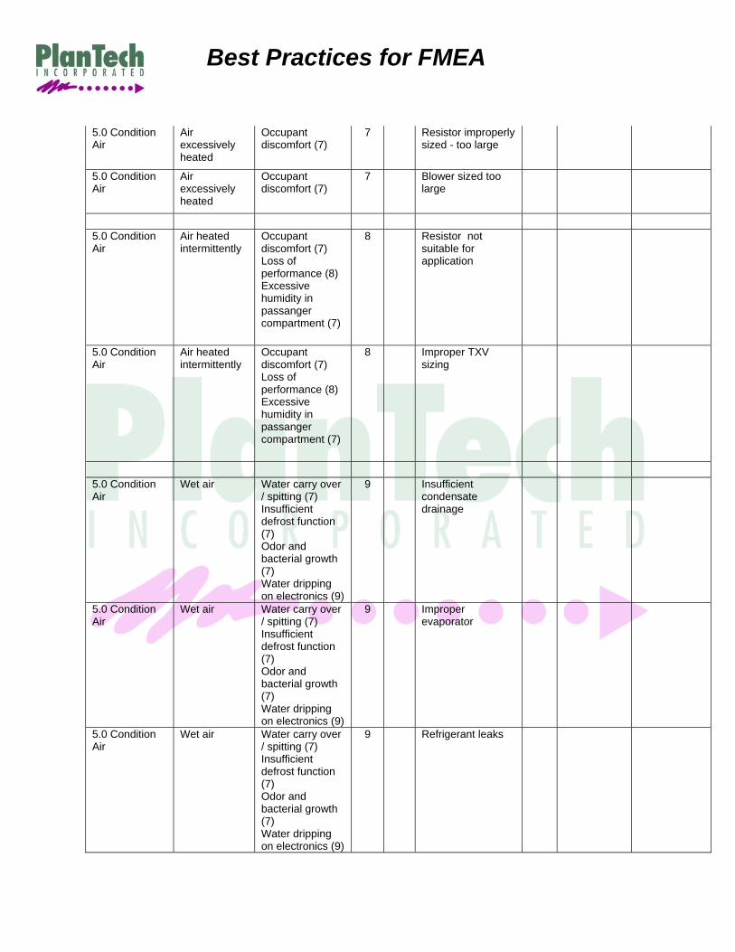
5.0 Condition Air
Air excessively heated
Occupant discomfort (7)
7 Resistor improperly sized - too large
5.0 Condition Air
Air excessively heated
Occupant discomfort (7)
7 Blower sized too large
5.0 Condition Air
Air heated intermittently
Occupant discomfort (7) Loss of performance (8) Excessive humidity in passanger compartment (7)
8 Resistor not suitable for application
5.0 Condition Air
Air heated intermittently
Occupant discomfort (7) Loss of performance (8) Excessive humidity in passanger compartment (7)
8 Improper TXV sizing
5.0 Condition Air
Wet air Water carry over / spitting (7) Insufficient defrost function (7) Odor and bacterial growth (7) Water dripping on electronics (9)
9 Insufficient condensate drainage
5.0 Condition Air
Wet air Water carry over / spitting (7) Insufficient defrost function (7) Odor and bacterial growth (7) Water dripping on electronics (9)
9 Improper evaporator
5.0 Condition Air
Wet air Water carry over / spitting (7) Insufficient defrost function (7) Odor and bacterial growth (7) Water dripping on electronics (9)
9 Refrigerant leaks
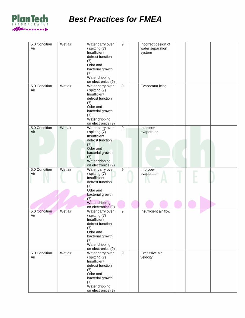
Best Practices for FMEA
5.0 Condition Air
Wet air Water carry over / spitting (7) Insufficient defrost function (7) Odor and bacterial growth (7) Water dripping on electronics (9)
9 Incorrect design of water separation system
5.0 Condition Air
Wet air Water carry over / spitting (7) Insufficient defrost function (7) Odor and bacterial growth (7) Water dripping on electronics (9)
9 Evaporator icing
5.0 Condition Air
Wet air Water carry over / spitting (7) Insufficient defrost function (7) Odor and bacterial growth (7) Water dripping on electronics (9)
9 Improper evaporator
5.0 Condition Air
Wet air Water carry over / spitting (7) Insufficient defrost function (7) Odor and bacterial growth (7) Water dripping on electronics (9)
9 Improper evaporator
5.0 Condition Air
Wet air Water carry over / spitting (7) Insufficient defrost function (7) Odor and bacterial growth (7) Water dripping on electronics (9)
9 Insufficient air flow
5.0 Condition Air
Wet air Water carry over / spitting (7) Insufficient defrost function (7) Odor and bacterial growth (7) Water dripping on electronics (9)
9 Excessive air velocity
Best Practices for FMEA
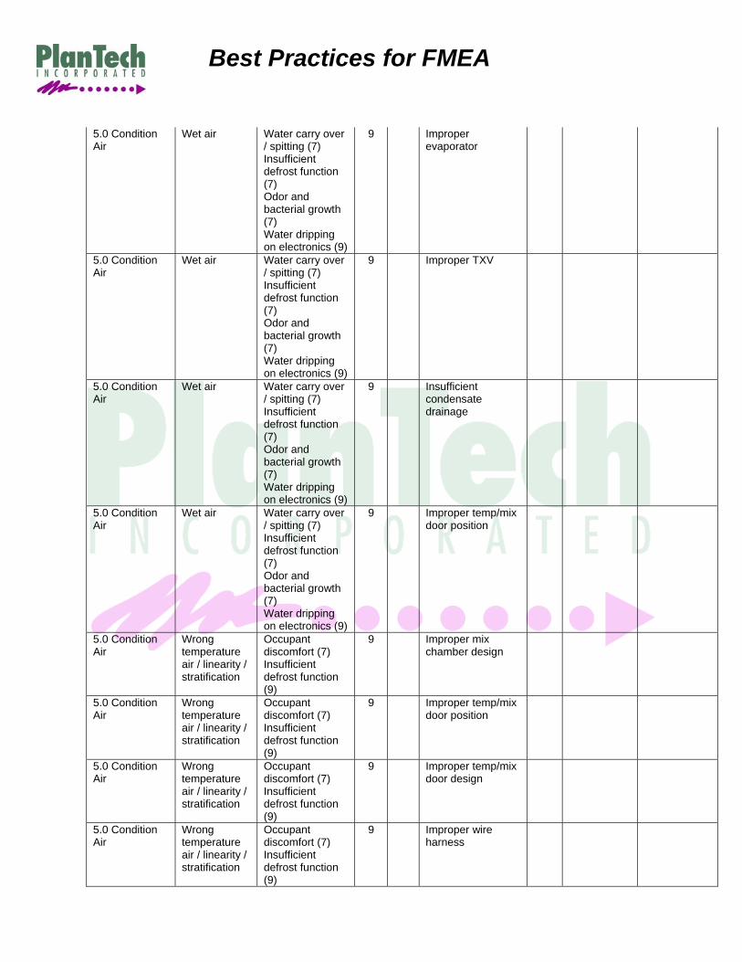
5.0 Condition Air
Wet air Water carry over / spitting (7) Insufficient defrost function (7) Odor and bacterial growth (7) Water dripping on electronics (9)
9 Improper evaporator
5.0 Condition Air
Wet air Water carry over / spitting (7) Insufficient defrost function (7) Odor and bacterial growth (7) Water dripping on electronics (9)
9 Improper TXV
5.0 Condition Air
Wet air Water carry over / spitting (7) Insufficient defrost function (7) Odor and bacterial growth (7) Water dripping on electronics (9)
9 Insufficient condensate drainage
5.0 Condition Air
Wet air Water carry over / spitting (7) Insufficient defrost function (7) Odor and bacterial growth (7) Water dripping on electronics (9)
9 Improper temp/mix door position
5.0 Condition Air
Wrong temperature air / linearity / stratification
Occupant discomfort (7) Insufficient defrost function (9)
9 Improper mix chamber design
5.0 Condition Air
Wrong temperature air / linearity / stratification
Occupant discomfort (7) Insufficient defrost function (9)
9 Improper temp/mix door position
5.0 Condition Air
Wrong temperature air / linearity / stratification
Occupant discomfort (7) Insufficient defrost function (9)
9 Improper temp/mix door design
5.0 Condition Air
Wrong temperature air / linearity / stratification
Occupant discomfort (7) Insufficient defrost function (9)
9 Improper wire harness

Best Practices for FMEA
5.0 Condition Air
Wrong temperature air / linearity / stratification
Occupant discomfort (7) Insufficient defrost function (9)
9 Improper kinematic design
5.0 Condition Air
Wrong temperature air / linearity / stratification
Occupant discomfort (7) Insufficient defrost function (9)
9 Improper mix chamber design
5.0 Condition Air
Wrong temperature air / linearity / stratification
Occupant discomfort (7) Insufficient defrost function (9)
9 Improper temp/mix door position
5.0 Condition Air
Wrong temperature air / linearity / stratification
Occupant discomfort (7) Insufficient defrost function (9)
9 Improper temp/mix door design
5.0 Condition Air
Wrong temperature air / linearity / stratification
Occupant discomfort (7) Insufficient defrost function (9)
9 Improper wire harness
5.0 Condition Air
Wrong temperature air / linearity / stratification
Occupant discomfort (7) Insufficient defrost function (9)
9 Improper kinematic design
Cooling System for a Vehicle
Item Function /
Requirements
Potential Failure Mode
Potential Effect(s) of Failure
SEV Cla
ss Potential
Cause(s) / Mechanism(s)
of Failure
O C C
Current Design
Controls Prevention
Current Design
Controls Detection
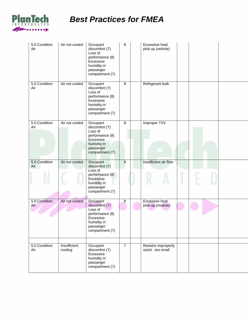
5.0 Condition Air
Air not cooled Occupant discomfort (7) Loss of performance (8) Excessive humidity in passanger compartment (7)
8 Evaporator freeze
5.0 Condition Air
Air not cooled Occupant discomfort (7) Loss of performance (8) Excessive humidity in passanger compartment (7)
8 Improper temp/mix door position
Best Practices for FMEA
5.0 Condition Air
Air not cooled Occupant discomfort (7) Loss of performance (8) Excessive humidity in passanger compartment (7)
8 Excessive heat pick-up (vehicle)
5.0 Condition Air
Air not cooled Occupant discomfort (7) Loss of performance (8) Excessive humidity in passanger compartment (7)
8 Refrigerant leak
5.0 Condition Air
Air not cooled Occupant discomfort (7) Loss of performance (8) Excessive humidity in passanger compartment (7)
8 Improper TXV
5.0 Condition Air
Air not cooled Occupant discomfort (7) Loss of performance (8) Excessive humidity in passanger compartment (7)
8 Insufficient air flow
5.0 Condition Air
Air not cooled Occupant discomfort (7) Loss of performance (8) Excessive humidity in passanger compartment (7)
8 Excessive heat pick-up (module)
5.0 Condition Air
Insufficient cooling
Occupant discomfort (7) Excessive humidity in passanger compartment (7)
7 Resistor improperly sized - too small

Best Practices for FMEA
5.0 Condition Air
Insufficient cooling
Occupant discomfort (7) Excessive humidity in passanger compartment (7)
7 Blower sized too small
5.0 Condition Air
Insufficient cooling
Occupant discomfort (7) Excessive humidity in passanger compartment (7)
7 Excessive heat pick-up in module due to heater core scrubbing
5.0 Condition Air
Insufficient cooling
Occupant discomfort (7) Excessive humidity in passanger compartment (7)
7 Excessive heat pick-up in module due to insufficient hot door sealing
5.0 Condition Air
Insufficient cooling
Occupant discomfort (7) Excessive humidity in passanger compartment (7)
7 Improper TXV sizing
5.0 Condition Air
Insufficient cooling
Occupant discomfort (7) Excessive humidity in passanger compartment (7)
7 Improper TXV superheat setting
5.0 Condition Air
Insufficient cooling
Occupant discomfort (7) Excessive humidity in passanger compartment (7)
7 Evaporator sized too small
5.0 Condition Air
Insufficient cooling
Occupant discomfort (7) Excessive humidity in passanger compartment (7)
7 Incorrect evap location/orientation
5.0 Condition Air
Insufficient cooling
Occupant discomfort (7) Excessive humidity in passanger compartment (7)
7 Evaporatoir fins blocked due to liner sizing - too large

Best Practices for FMEA
5.0 Condition Air
Insufficient cooling
Occupant discomfort (7) Excessive humidity in passanger compartment (7)
7 Refrigerant leak at TXV to evaporator pipes.- Incorrect sealing surface
5.0 Condition Air
Insufficient cooling
Occupant discomfort (7) Excessive humidity in passanger compartment (7)
7 Refrigerant leak at tube to evaporator joint - Insufficient flux during brazing process
5.0 Condition Air
Insufficient cooling
Occupant discomfort (7) Excessive humidity in passanger compartment (7)
7 Refrigerant leak due to damage during mating of evaporator assembly to module
5.0 Condition Air
Insufficient cooling
Occupant discomfort (7) Excessive humidity in passanger compartment (7)
7 Design allows creation of refrigerant leaks due to mishandling of Evaporator assembly
5.0 Condition Air
Insufficient cooling
Occupant discomfort (7) Excessive humidity in passanger compartment (7)
7 Case leakage due to poor housing design (tongue and groove, parting lines with abrupt plane changes, uneven sealing surface)
5.0 Condition Air
Insufficient cooling
Occupant discomfort (7) Excessive humidity in passanger compartment (7)
7 Case leakage due to poor fit between evaporator, liner, and housings
5.0 Condition Air
Insufficient cooling
Occupant discomfort (7) Excessive humidity in passanger compartment (7)
7 Bypass air leakage due to poor housing design (tongue and groove, parting lines with abrupt plane changes, uneven sealing surface)
5.0 Condition Air
Insufficient cooling
Occupant discomfort (7) Excessive humidity in passanger compartment (7)
7 Bypass air leakage due to poor fit between evaporator, liner and housings
Best Practices for FMEA
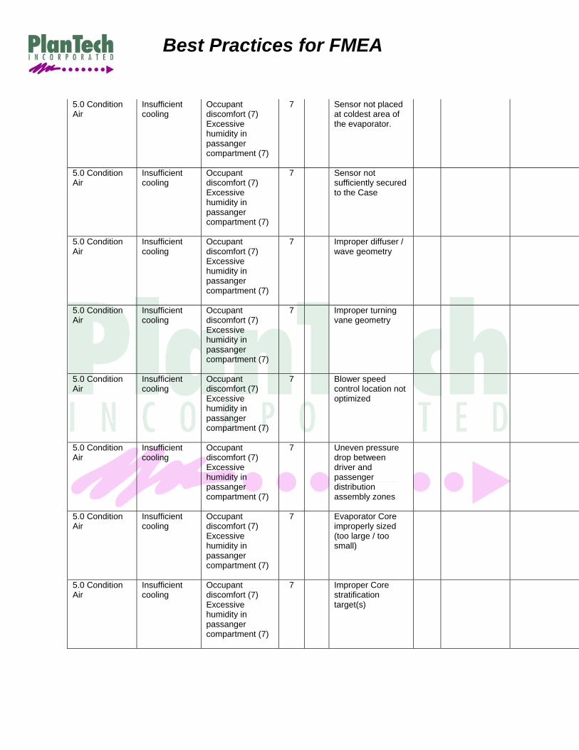
5.0 Condition Air
Insufficient cooling
Occupant discomfort (7) Excessive humidity in passanger compartment (7)
7 Sensor not placed at coldest area of the evaporator.
5.0 Condition Air
Insufficient cooling
Occupant discomfort (7) Excessive humidity in passanger compartment (7)
7 Sensor not sufficiently secured to the Case
5.0 Condition Air
Insufficient cooling
Occupant discomfort (7) Excessive humidity in passanger compartment (7)
7 Improper diffuser / wave geometry
5.0 Condition Air
Insufficient cooling
Occupant discomfort (7) Excessive humidity in passanger compartment (7)
7 Improper turning vane geometry
5.0 Condition Air
Insufficient cooling
Occupant discomfort (7) Excessive humidity in passanger compartment (7)
7 Blower speed control location not optimized
5.0 Condition Air
Insufficient cooling
Occupant discomfort (7) Excessive humidity in passanger compartment (7)
7 Uneven pressure drop between driver and passenger distribution assembly zones
5.0 Condition Air
Insufficient cooling
Occupant discomfort (7) Excessive humidity in passanger compartment (7)
7 Evaporator Core improperly sized (too large / too small)
5.0 Condition Air
Insufficient cooling
Occupant discomfort (7) Excessive humidity in passanger compartment (7)
7 Improper Core stratification target(s)

Best Practices for FMEA
5.0 Condition Air
Insufficient cooling
Occupant discomfort (7) Excessive humidity in passanger compartment (7)
7 Improper TXV super heat setting
5.0 Condition Air
Insufficient cooling
Occupant discomfort (7) Excessive humidity in passanger compartment (7)
7 Improper TXV sizing
5.0 Condition Air
Air excessively cooled
Occupant discomfort (7)
7 Resistor improperly sized - too large
5.0 Condition Air
Air excessively cooled
Occupant discomfort (7)
7 Blower sized too large
5.0 Condition Air
Air cooled intermittently
Occupant discomfort (7) Loss of performance (8) Excessive humidity in passanger compartment (7)
8 Resistor not suitable for application
5.0 Condition Air
Air cooled intermittently
Occupant discomfort (7) Loss of performance (8) Excessive humidity in passanger compartment (7)
8 Improper TXV sizing
5.0 Condition Air
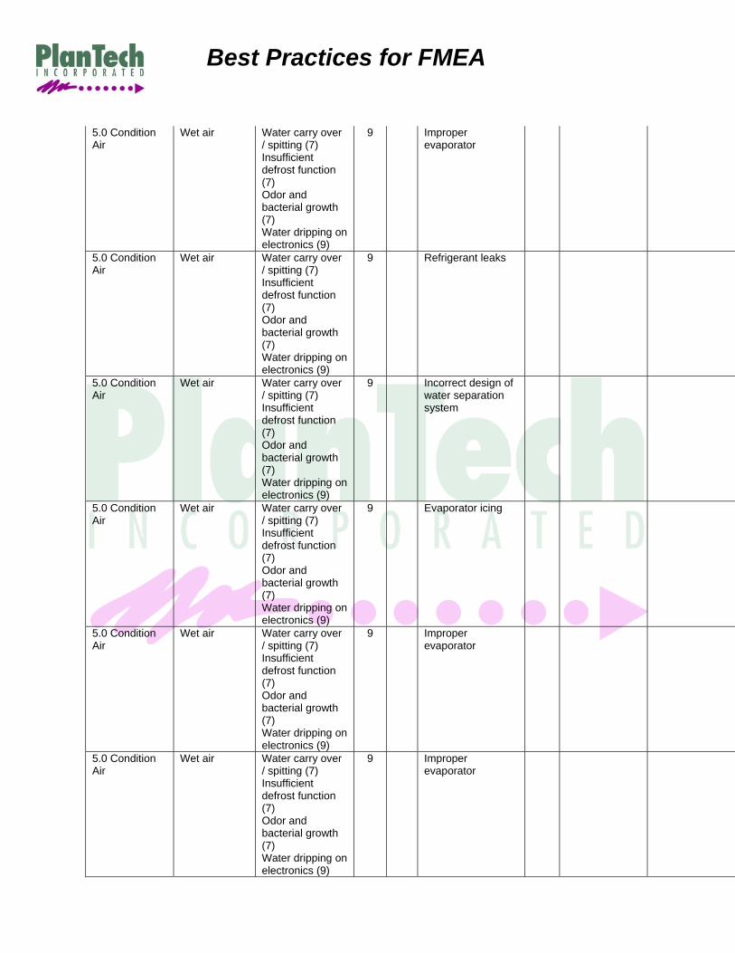
Wet air Water carry over / spitting (7) Insufficient defrost function (7) Odor and bacterial growth (7) Water dripping on electronics (9)
9 Insufficient condensate drainage
Best Practices for FMEA
5.0 Condition Air
Wet air Water carry over / spitting (7) Insufficient defrost function (7) Odor and bacterial growth (7) Water dripping on electronics (9)
9 Improper evaporator
5.0 Condition Air
Wet air Water carry over / spitting (7) Insufficient defrost function (7) Odor and bacterial growth (7) Water dripping on electronics (9)
9 Refrigerant leaks
5.0 Condition Air
Wet air Water carry over / spitting (7) Insufficient defrost function (7) Odor and bacterial growth (7) Water dripping on electronics (9)
9 Incorrect design of water separation system
5.0 Condition Air
Wet air Water carry over / spitting (7) Insufficient defrost function (7) Odor and bacterial growth (7) Water dripping on electronics (9)
9 Evaporator icing
5.0 Condition Air
Wet air Water carry over / spitting (7) Insufficient defrost function (7) Odor and bacterial growth (7) Water dripping on electronics (9)
9 Improper evaporator
5.0 Condition Air
Wet air Water carry over / spitting (7) Insufficient defrost function (7) Odor and bacterial growth (7) Water dripping on electronics (9)
9 Improper evaporator

Best Practices for FMEA
5.0 Condition Air
Wet air Water carry over / spitting (7) Insufficient defrost function (7) Odor and bacterial growth (7) Water dripping on electronics (9)
9 Insufficient air flow
5.0 Condition Air
Wet air Water carry over / spitting (7) Insufficient defrost function (7) Odor and bacterial growth (7) Water dripping on electronics (9)
9 Excessive air velocity
5.0 Condition Air
Wet air Water carry over / spitting (7) Insufficient defrost function (7) Odor and bacterial growth (7) Water dripping on electronics (9)
9 Improper evaporator
5.0 Condition Air
Wet air Water carry over / spitting (7) Insufficient defrost function (7) Odor and bacterial growth (7) Water dripping on electronics (9)
9 Improper TXV
5.0 Condition Air
Wet air Water carry over / spitting (7) Insufficient defrost function (7) Odor and bacterial growth (7) Water dripping on electronics (9)
9 Insufficient condensate drainage
5.0 Condition Air
Wet air Water carry over / spitting (7) Insufficient defrost function (7) Odor and bacterial growth (7) Water dripping on electronics (9)
9 Improper temp/mix door position
Best Practices for FMEA
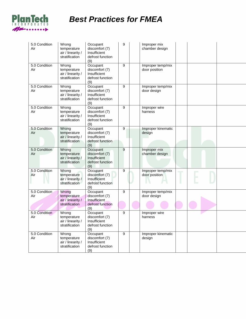
5.0 Condition Air
Wrong temperature air / linearity / stratification
Occupant discomfort (7) Insufficient defrost function (9)
9 Improper mix chamber design
5.0 Condition Air
Wrong temperature air / linearity / stratification
Occupant discomfort (7) Insufficient defrost function (9)
9 Improper temp/mix door position
5.0 Condition Air
Wrong temperature air / linearity / stratification
Occupant discomfort (7) Insufficient defrost function (9)
9 Improper temp/mix door design
5.0 Condition Air
Wrong temperature air / linearity / stratification
Occupant discomfort (7) Insufficient defrost function (9)
9 Improper wire harness
5.0 Condition Air
Wrong temperature air / linearity / stratification
Occupant discomfort (7) Insufficient defrost function (9)
9 Improper kinematic design
5.0 Condition Air
Wrong temperature air / linearity / stratification
Occupant discomfort (7) Insufficient defrost function (9)
9 Improper mix chamber design
5.0 Condition Air
Wrong temperature air / linearity / stratification
Occupant discomfort (7) Insufficient defrost function (9)
9 Improper temp/mix door position
5.0 Condition Air
Wrong temperature air / linearity / stratification
Occupant discomfort (7) Insufficient defrost function (9)
9 Improper temp/mix door design
5.0 Condition Air
Wrong temperature air / linearity / stratification
Occupant discomfort (7) Insufficient defrost function (9)
9 Improper wire harness
5.0 Condition Air
Wrong temperature air / linearity / stratification
Occupant discomfort (7) Insufficient defrost function (9)
9 Improper kinematic design