
Best Practice Guidelines for PV Cost Calculation · PDF fileBest Practice Guidelines for PV...
20
Best Practice Guidelines for PV Cost Calculation Accounting for Technical Risks and Assumptions in PV LCOE Deliverable D3.2 Best Practice Checklists This annex presents 6 checklists which are aimed for use for utility- scale (ground-mounted) and commercial rooftop PV installations. The checklists for residential systems are presented in the report Technical Bankability Guidelines - Recommendations to Enhance Technical Quality of PV Investments.
Transcript of Best Practice Guidelines for PV Cost Calculation · PDF fileBest Practice Guidelines for PV...

Best Practice Guidelines for PV Cost Calculation
Accounting for Technical Risks and Assumptions in PV LCOE
Deliverable D3.2
Best Practice Checklists
This annex presents 6 checklists which are aimed for use for utility-scale (ground-mounted) and commercial rooftop PV installations. The checklists for residential systems are presented in the report Technical Bankability Guidelines - Recommendations to Enhance Technical Quality of PV Investments.
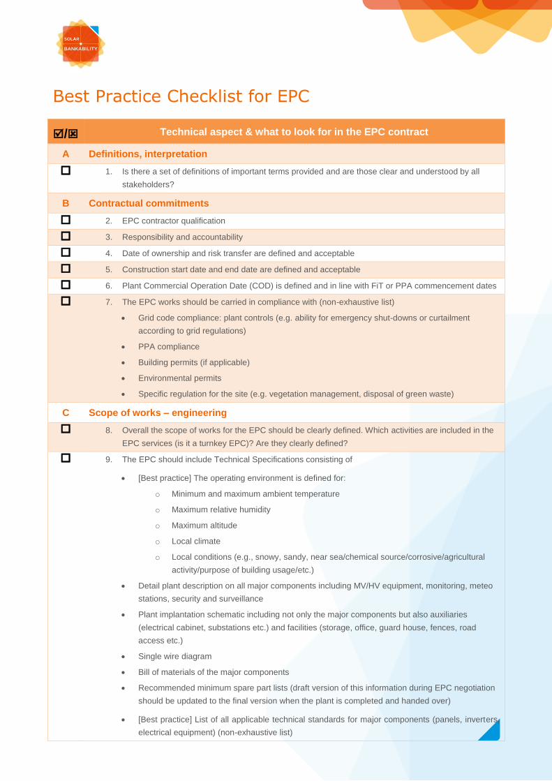
Best Practice Checklist for EPC
/ Technical aspect & what to look for in the EPC contract
A Definitions, interpretation
1. Is there a set of definitions of important terms provided and are those clear and understood by all
stakeholders?
B Contractual commitments
2. EPC contractor qualification
3. Responsibility and accountability
4. Date of ownership and risk transfer are defined and acceptable
5. Construction start date and end date are defined and acceptable
6. Plant Commercial Operation Date (COD) is defined and in line with FiT or PPA commencement dates
7. The EPC works should be carried in compliance with (non-exhaustive list)
Grid code compliance: plant controls (e.g. ability for emergency shut-downs or curtailment
according to grid regulations)
PPA compliance
Building permits (if applicable)
Environmental permits
Specific regulation for the site (e.g. vegetation management, disposal of green waste)
C Scope of works – engineering
8. Overall the scope of works for the EPC should be clearly defined. Which activities are included in the
EPC services (is it a turnkey EPC)? Are they clearly defined?
9. The EPC should include Technical Specifications consisting of
[Best practice] The operating environment is defined for:
o Minimum and maximum ambient temperature
o Maximum relative humidity
o Maximum altitude
o Local climate
o Local conditions (e.g., snowy, sandy, near sea/chemical source/corrosive/agricultural
activity/purpose of building usage/etc.)
Detail plant description on all major components including MV/HV equipment, monitoring, meteo
stations, security and surveillance
Plant implantation schematic including not only the major components but also auxiliaries
(electrical cabinet, substations etc.) and facilities (storage, office, guard house, fences, road
access etc.)
Single wire diagram
Bill of materials of the major components
Recommended minimum spare part lists (draft version of this information during EPC negotiation
should be updated to the final version when the plant is completed and handed over)
[Best practice] List of all applicable technical standards for major components (panels, inverters,
electrical equipment) (non-exhaustive list)

o CE Compliance
o Panel: IEC61215, IEC61730, IEC61701, IEC62716, IEC62804, IEC62108 (CPV)
o IR/EL: IEC60904-12 & 13
o Inverter: IEC62109
o Electrical equipment: IEC61000
o Tracker: IEC62817, IEC62727
o Design and installation: IEC TS 62548
o Commissioning: IEC62446
o Performance monitoring: IEC61724
10. Who is responsible for grid connection and the infrastructure to connect the PV plant to the grid
(transformer, export lines, substation) is clearly defined
11. Site suitability (ground installation)
Geotechnical and soil study
Any flood risk
Other constraints (chemical in the air, corrosive air, etc.)
Site suitability (rooftop installation)
Roof stability study
Structural requirements of roof and mounting structure (both static/snow load and dynamic/wind
load
Lightning protection requirement
Fire protection (PV system should not be built across fire protection walls); design should be in
compliance with the building fire protection codes
Requirement for weathering protection (lifetime of roofing film)
12. If the site study has been done and the results have been shared with the owner and the EPC, the
EPC contract should clearly acknowledge that the contractor has reviewed the results of the study
and has designed the PV system taking into account the site conditions and constraints
13. For rooftop system, the roof should be weatherproof throughout operations of PV plant without major
overhaul of roof laminate layer
14. Estimation of plant yield/production should follow best practice guidelines (see “Best Practice
Checklist for Long-Term Yield Assessment”)
15. The plant design and estimated yield/production should be validated by third party
D Scope of works – procurement
16. All major components should be visually inspected at delivery
17. All modules should be tested for STC performance according to the IEC60904 standards at the
factory and the test data should be submitted to the EPC contractor for verification
[Best practice] All modules should be inspected with electroluminescence imaging camera at the
factory and the test data should be submitted to the EPC contractor for verification
18. PV modules should be sampled and tested after delivery and before acceptance
List of test (and criteria) should be included in the EPC contract
Tests are to be done by an accredited independent test laboratory
19. [Best practice] Transportation and handling requirements on components should be specified
20. [Best practice] EPC contractor is required to perform factory inspection on the module factory
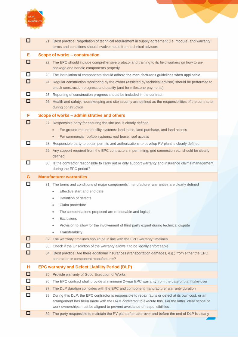
21. [Best practice] Negotiation of technical requirement in supply agreement (i.e. module) and warranty
terms and conditions should involve inputs from technical advisors
E Scope of works – construction
22. The EPC should include comprehensive protocol and training to its field workers on how to un-
package and handle components properly
23. The installation of components should adhere the manufacturer’s guidelines when applicable
24. Regular construction monitoring by the owner (assisted by technical advisor) should be performed to
check construction progress and quality (and for milestone payments)
25. Reporting of construction progress should be included in the contract
26. Health and safety, housekeeping and site security are defined as the responsibilities of the contractor
during construction
F Scope of works – administrative and others
27. Responsible party for securing the site use is clearly defined:
For ground-mounted utility systems: land lease, land purchase, and land access
For commercial rooftop systems: roof lease, roof access
28. Responsible party to obtain permits and authorizations to develop PV plant is clearly defined
29. Any support required from the EPC contractors in permitting, grid connection etc. should be clearly
defined
30. Is the contractor responsible to carry out or only support warranty and insurance claims management
during the EPC period?
G Manufacturer warranties
31. The terms and conditions of major components’ manufacturer warranties are clearly defined
Effective start and end date
Definition of defects
Claim procedure
The compensations proposed are reasonable and logical
Exclusions
Provision to allow for the involvement of third party expert during technical dispute
Transferability
32. The warranty timelines should be in line with the EPC warranty timelines
33. Check if the jurisdiction of the warranty allows it to be legally enforceable
34. [Best practice] Are there additional insurances (transportation damages, e.g.) from either the EPC
contractor or component manufacturer?
H EPC warranty and Defect Liability Period (DLP)
35. Provide warranty of Good Execution of Works
36. The EPC contract shall provide at minimum 2-year EPC warranty from the date of plant take-over
37. The DLP duration coincides with the EPC and component manufacturer warranty duration
38. During this DLP, the EPC contractor is responsible to repair faults or defect at its own cost, or an
arrangement has been made with the O&M contractor to execute this. For the latter, clear scope of
work ownerships must be aligned to prevent avoidance of responsibilities
39. The party responsible to maintain the PV plant after take-over and before the end of DLP is clearly

defined
I Key performance indicators (KPIs) and guarantees
40. The EPC contract should have key performance indicators for two aspects
Completion timeline: guaranteed completion date
System performance and quality: guaranteed performance ratio (PR) or guaranteed output
41. The guaranteed PR or output should be calculated in a long-term yield estimation exercise using
correct technical assumptions, i.e. all relevant losses and uncertainties
42. Liquidated damages (LD) or penalties should be assigned in the contract in case the guaranteed KPIs
are not met
43. Completion delay LDs should be in line with the project revenue loss due to lateness in project
entering operation. The LD is commonly a % of EPC price for each day of delay
44. Performance LDs should be in line with the project revenue loss when the system is not meeting the
guaranteed performance level. The LD is commonly a % of EPC price for each point of PR or output
below the guaranteed value
45. Maximum amount of LD (LD cap) to limit contractor’s liability is usually included in the EPC contract.
E.g., delay LD and performance LD could each be capped at 20% of the EPC contract price and the
combined cap is 30% of the EPC contract price
J Commissioning and acceptance
46. The EPC contract should include plant provisional and final commissioning
47. Short term performance test should be carried out after the PV system completes the construction
phase
48. Provisional test set-up should include appropriate:
Duration of the test
Irradiance threshold
Monitoring system, including measurement sampling rate and averaging method
49. The calculation method for the key performance indicator for provisional acceptance should account
for short-term effect on temperature and irradiance
50. Final acceptance plant performance should be carried out after the plant has been in operation for a
representative period of time (2 years after provisional acceptance)
51. Final performance test set-up should include appropriate
Irradiance threshold
Monitoring system, including measurement sampling rate and averaging method
52. The calculation method for the key performance indicator for final acceptance should account for:
Annual degradation
Plant availability
53. Measurement of irradiance to assess plant performance
Irradiance measurements
Measurement in the POA according to the Secondary Standard or First Class quality
classification (ISO9060:1990)
Minimum requirement: one measurement device (pyranometer of high quality)
[Best practice] At least 2 pyranometers
If different array orientations, one pyranometer per orientation – careful assignment for proper
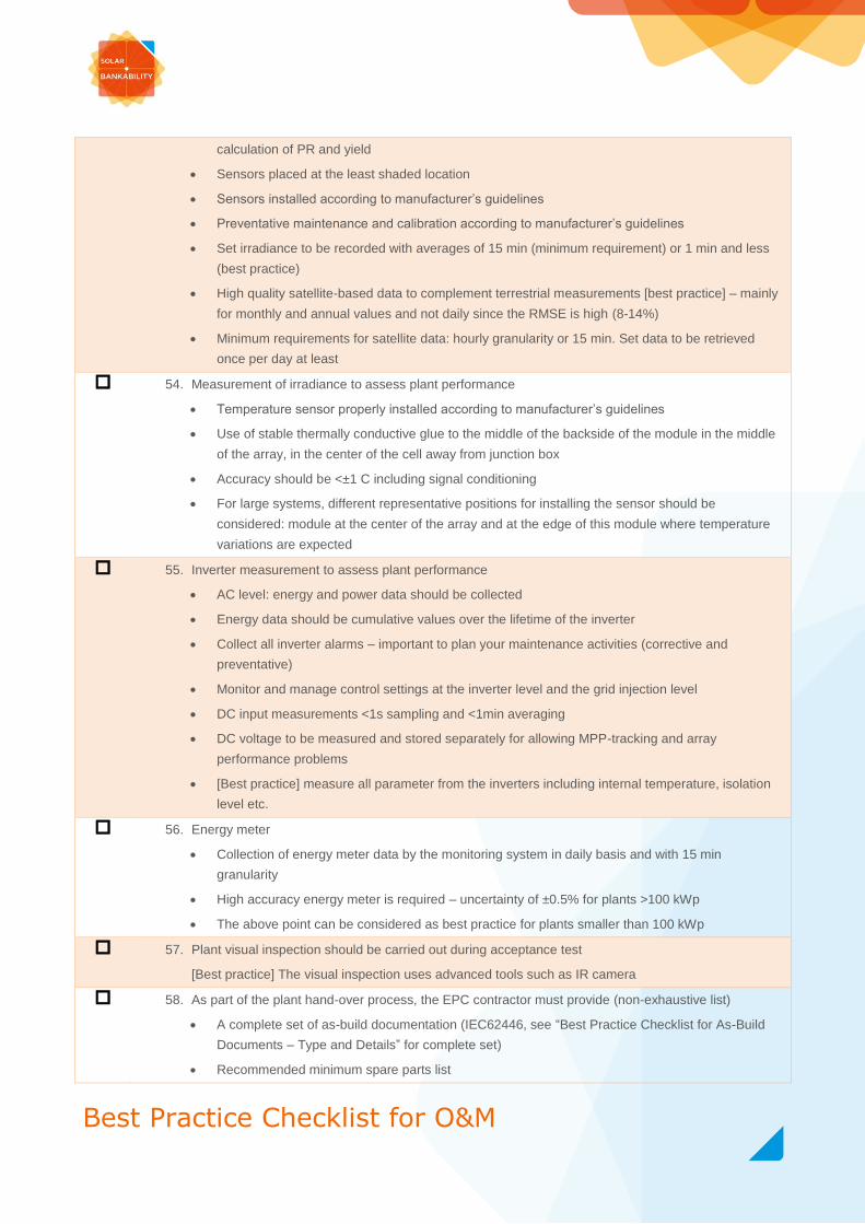
calculation of PR and yield
Sensors placed at the least shaded location
Sensors installed according to manufacturer’s guidelines
Preventative maintenance and calibration according to manufacturer’s guidelines
Set irradiance to be recorded with averages of 15 min (minimum requirement) or 1 min and less
(best practice)
High quality satellite-based data to complement terrestrial measurements [best practice] – mainly
for monthly and annual values and not daily since the RMSE is high (8-14%)
Minimum requirements for satellite data: hourly granularity or 15 min. Set data to be retrieved
once per day at least
54. Measurement of irradiance to assess plant performance
Temperature sensor properly installed according to manufacturer’s guidelines
Use of stable thermally conductive glue to the middle of the backside of the module in the middle
of the array, in the center of the cell away from junction box
Accuracy should be <±1 C including signal conditioning
For large systems, different representative positions for installing the sensor should be
considered: module at the center of the array and at the edge of this module where temperature
variations are expected
55. Inverter measurement to assess plant performance
AC level: energy and power data should be collected
Energy data should be cumulative values over the lifetime of the inverter
Collect all inverter alarms – important to plan your maintenance activities (corrective and
preventative)
Monitor and manage control settings at the inverter level and the grid injection level
DC input measurements <1s sampling and <1min averaging
DC voltage to be measured and stored separately for allowing MPP-tracking and array
performance problems
[Best practice] measure all parameter from the inverters including internal temperature, isolation
level etc.
56. Energy meter
Collection of energy meter data by the monitoring system in daily basis and with 15 min
granularity
High accuracy energy meter is required – uncertainty of ±0.5% for plants >100 kWp
The above point can be considered as best practice for plants smaller than 100 kWp
57. Plant visual inspection should be carried out during acceptance test
[Best practice] The visual inspection uses advanced tools such as IR camera
58. As part of the plant hand-over process, the EPC contractor must provide (non-exhaustive list)
A complete set of as-build documentation (IEC62446, see “Best Practice Checklist for As-Build
Documents – Type and Details” for complete set)
Recommended minimum spare parts list
Best Practice Checklist for O&M
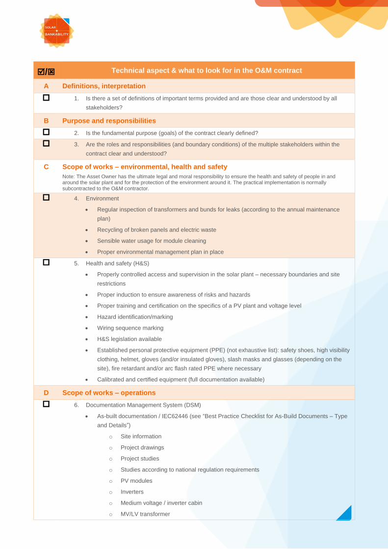
/ Technical aspect & what to look for in the O&M contract
A Definitions, interpretation
1. Is there a set of definitions of important terms provided and are those clear and understood by all
stakeholders?
B Purpose and responsibilities
2. Is the fundamental purpose (goals) of the contract clearly defined?
3. Are the roles and responsibilities (and boundary conditions) of the multiple stakeholders within the
contract clear and understood?
C Scope of works – environmental, health and safety
Note: The Asset Owner has the ultimate legal and moral responsibility to ensure the health and safety of people in and around the solar plant and for the protection of the environment around it. The practical implementation is normally subcontracted to the O&M contractor.
4. Environment
Regular inspection of transformers and bunds for leaks (according to the annual maintenance
plan)
Recycling of broken panels and electric waste
Sensible water usage for module cleaning
Proper environmental management plan in place
5. Health and safety (H&S)
Properly controlled access and supervision in the solar plant – necessary boundaries and site
restrictions
Proper induction to ensure awareness of risks and hazards
Proper training and certification on the specifics of a PV plant and voltage level
Hazard identification/marking
Wiring sequence marking
H&S legislation available
Established personal protective equipment (PPE) (not exhaustive list): safety shoes, high visibility
clothing, helmet, gloves (and/or insulated gloves), slash masks and glasses (depending on the
site), fire retardant and/or arc flash rated PPE where necessary
Calibrated and certified equipment (full documentation available)
D Scope of works – operations
6. Documentation Management System (DSM)
As-built documentation / IEC62446 (see “Best Practice Checklist for As-Build Documents – Type
and Details”)
o Site information
o Project drawings
o Project studies
o Studies according to national regulation requirements
o PV modules
o Inverters
o Medium voltage / inverter cabin
o MV/LV transformer

o HV switchgear
o UPS and batteries
o Mounting
Management and control
o Define type of storage (physical or/and electronical)
o Ensure electronic copy of all documents
o Ensure controlled access to documents
o Ensure authorization for modifications – keep a logbook on name of person who
modified the document, date of modification, reason for modification and further
information e.g. link to the work orders and service activities
o Ensure history of the documents (versioning)
Record control (see “Best Practice Checklist for Record Control”)
7. [Best practice] Predictive maintenance
Define scope of this cluster, the type of performance analysis, the level (portfolio level, plant level,
inverter level, string level)
Define the monitoring requirements needed to perform predictive maintenance, provide basic
trending and comparison functionality
8. Power generation forecasting
Ensure a service level agreement with the forecast provider
Define the purpose and consequently the requirements for power forecasting (e.g. time horizon,
time resolution, update frequency)
9. Reporting (see “Best Practice Checklist for Reporting Indicators”)
10. Regulatory compliance
Grid code compliance: plant controls (e.g. ability for emergency shut-downs or curtailment
according to grid regulations)
PPA compliance
Building permits (if applicable)
Environmental permits
Specific regulation for the site (e.g. vegetation management, disposal of green waste)
11. Management of change: define responsibilities and involvement when PV plant needs to be adjusted
after the Commercial Operation Date: e.g. spare parts, site operation plan, annual maintenance plan
etc.
12. Warranty management
Warranty of Good Execution of Works
Warranty of Equipment
Performance Warranty: agree on reporting period
Classification of anomalies and malfunctions: Pending Works, Insufficiencies, Defects, Failure or
malfunction of equipment
13. Insurance claims management
E Scope of works – maintenance
14. Inclusion of an adequate Preventive Maintenance Plan
15. The minimum requirements for preventative tasks and their frequency follow the manufacturer’s

guidelines when applicable
16. The minimum requirements for preventative tasks and their frequency should respect relevant
national standards
17. Corrective maintenance (CM)
Fault diagnosis (troubleshooting)
Repair and temporary repairs
Agreed response times and/or minimum repair times
Clear definition of “boarders” and “limitations” of CM tasks, especially with preventative
maintenance and extraordinary maintenance. Definition of yearly cap of CM works (when
applicable)
18. Extraordinary maintenance
Define what is included in this cluster
o Damages that are a consequence of a Force Majeure event
o Damages as a consequence of a theft or a fire
o Serial defects on equipment, occurring suddenly and after months or years from plant
start-up
o Modifications required by regulatory changes
o Agreed interventions for reconditioning, renewal and technological updating
Define the rules on how to execute tasks and prepare quotations – ways of payment
19. Additional services: define what is included in this cluster and how this service is paid (non-exhaustive
list)
Module cleaning
Vegetation management
Road maintenance
Snow removal
Pest control
Waste disposal
Maintenance of buildings
Perimeter fencing and repairs
Maintenance of security equipment
String measurements – to the extent exceeding the agreed level of preventative maintenance
Thermal inspections – to the extent exceeding the agreed level of preventative maintenance
Meter weekly/monthly readings and data entry on fiscal registers or in authority web portals for
FiT tariff assessment (where applicable)
F Scope of works – data and monitoring
20. Irradiance measurements
Measurement in the POA according to the Secondary Standard or First Class quality
classification (ISO9060:1990)
Minimum requirement: one measurement device (pyranometer of high quality)
[Best practice] At least 2 pyranometers
If different array orientations, one pyranometer per orientation – careful assignment for proper
calculation of PR and yield
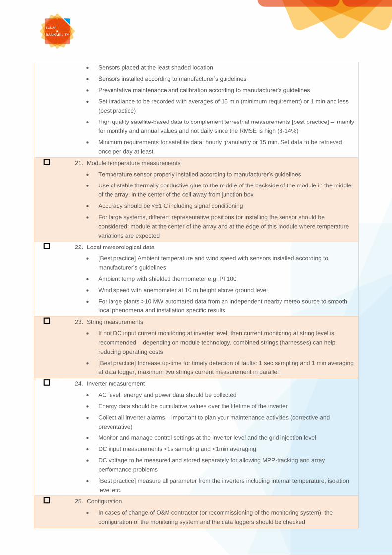
Sensors placed at the least shaded location
Sensors installed according to manufacturer’s guidelines
Preventative maintenance and calibration according to manufacturer’s guidelines
Set irradiance to be recorded with averages of 15 min (minimum requirement) or 1 min and less
(best practice)
High quality satellite-based data to complement terrestrial measurements [best practice] – mainly
for monthly and annual values and not daily since the RMSE is high (8-14%)
Minimum requirements for satellite data: hourly granularity or 15 min. Set data to be retrieved
once per day at least
21. Module temperature measurements
Temperature sensor properly installed according to manufacturer’s guidelines
Use of stable thermally conductive glue to the middle of the backside of the module in the middle
of the array, in the center of the cell away from junction box
Accuracy should be <±1 C including signal conditioning
For large systems, different representative positions for installing the sensor should be
considered: module at the center of the array and at the edge of this module where temperature
variations are expected
22. Local meteorological data
[Best practice] Ambient temperature and wind speed with sensors installed according to
manufacturer’s guidelines
Ambient temp with shielded thermometer e.g. PT100
Wind speed with anemometer at 10 m height above ground level
For large plants >10 MW automated data from an independent nearby meteo source to smooth
local phenomena and installation specific results
23. String measurements
If not DC input current monitoring at inverter level, then current monitoring at string level is
recommended – depending on module technology, combined strings (harnesses) can help
reducing operating costs
[Best practice] Increase up-time for timely detection of faults: 1 sec sampling and 1 min averaging
at data logger, maximum two strings current measurement in parallel
24. Inverter measurement
AC level: energy and power data should be collected
Energy data should be cumulative values over the lifetime of the inverter
Collect all inverter alarms – important to plan your maintenance activities (corrective and
preventative)
Monitor and manage control settings at the inverter level and the grid injection level
DC input measurements <1s sampling and <1min averaging
DC voltage to be measured and stored separately for allowing MPP-tracking and array
performance problems
[Best practice] measure all parameter from the inverters including internal temperature, isolation
level etc.
25. Configuration
In cases of change of O&M contractor (or recommissioning of the monitoring system), the
configuration of the monitoring system and the data loggers should be checked

[Best practice] if technically available, auto-configuration is recommended – e.g. automatic
collection of inverter and sensor IDs and labels
Back up of the configuration should be in place
26. Energy meter
Collection of energy meter data by the monitoring system in daily basis and with 15 min
granularity
High accuracy energy meter is required – uncertainty of ±0.5% for plants >100 kWp
The above point can be considered as best practice for plants smaller than 100 kWp
27. AC circuit / protection relay
[Best practice] Monitor the AC switch position for (sub) plants. Read the alarms from the
protection relay via communication bus if possible
28. Data loggers
Sufficient memory to store at least one month of data
Historical data should be backed up
After communication failure, the data logger should resend all pending information
The entire installation (monitoring system, signal converters, data loggers, measurement devices)
should be protected by a UPS
[Best practices] Memory to store at least six months of data and full data backup in the cloud.
Separate remote server to monitor the status of the data loggers and inform the operations. The
system should be an open protocol to allow transition between monitoring platforms. If possible,
reboot itself once per day (during night time) to increase reliability
29. Alarms
Minimum requirement: alarms sent by email (non-exhaustive list)
o Loss of communication
o Plant stop
o Inverter stop
o Plant with low performance
o Inverter with low performance (e.g. due to overheating)
[Best practice] (non-exhaustive list)
o String without current
o Plant under UPS operation
o Intrusion detection
o Fire alarm detection
o Discretion alarm (or alarm aggregation)
30. Dashboard / web portal
Minimum requirements for features of the monitoring system (non-exhaustive list)
o Web portal accessible 24h/365d
o Graphs of irradiation, energy production, performance and yield
o Downloadable tables with all the registered figures
o Alarms register
[Best practices] (non-exhaustive list)
o User configurable dashboard
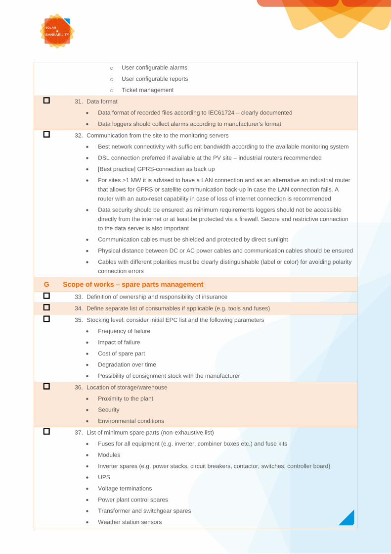
o User configurable alarms
o User configurable reports
o Ticket management
31. Data format
Data format of recorded files according to IEC61724 – clearly documented
Data loggers should collect alarms according to manufacturer's format
32. Communication from the site to the monitoring servers
Best network connectivity with sufficient bandwidth according to the available monitoring system
DSL connection preferred if available at the PV site – industrial routers recommended
[Best practice] GPRS-connection as back up
For sites >1 MW it is advised to have a LAN connection and as an alternative an industrial router
that allows for GPRS or satellite communication back-up in case the LAN connection fails. A
router with an auto-reset capability in case of loss of internet connection is recommended
Data security should be ensured: as minimum requirements loggers should not be accessible
directly from the internet or at least be protected via a firewall. Secure and restrictive connection
to the data server is also important
Communication cables must be shielded and protected by direct sunlight
Physical distance between DC or AC power cables and communication cables should be ensured
Cables with different polarities must be clearly distinguishable (label or color) for avoiding polarity
connection errors
G Scope of works – spare parts management
33. Definition of ownership and responsibility of insurance
34. Define separate list of consumables if applicable (e.g. tools and fuses)
35. Stocking level: consider initial EPC list and the following parameters
Frequency of failure
Impact of failure
Cost of spare part
Degradation over time
Possibility of consignment stock with the manufacturer
36. Location of storage/warehouse
Proximity to the plant
Security
Environmental conditions
37. List of minimum spare parts (non-exhaustive list)
Fuses for all equipment (e.g. inverter, combiner boxes etc.) and fuse kits
Modules
Inverter spares (e.g. power stacks, circuit breakers, contactor, switches, controller board)
UPS
Voltage terminations
Power plant control spares
Transformer and switchgear spares
Weather station sensors
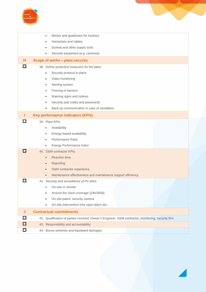
Motors and gearboxes for trackers
Harnesses and cables
Screws and other supply tools
Security equipment (e.g. cameras)
H Scope of works – plant security
38. Define protective measures for the plant
Security protocol in place
Video monitoring
Alerting system
Fencing or barriers
Warning signs and notices
Security pad codes and passwords
Back up communication in case of vandalism
I Key performance indicators (KPIs)
39. Plant KPIs
Availability
Energy-based availability
Performance Ratio
Energy Performance Index
40. O&M contractor KPIs
Reaction time
Reporting
O&M contractor experience
Maintenance effectiveness and maintenance support efficiency
41. Security and surveillance of PV plant
On-site or remote
Around the clock coverage (24h/365d)
On-site patrol, security camera
On-site intervention time upon alarm etc.
J Contractual commitments
42. Qualification of parties involved: Owner’s Engineer, O&M contractor, monitoring, security firm
43. Responsibility and accountability
44. Bonus schemes and liquidated damages
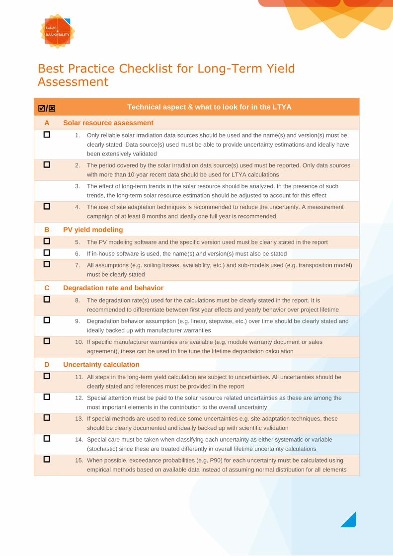
Best Practice Checklist for Long-Term Yield Assessment
/ Technical aspect & what to look for in the LTYA
A Solar resource assessment
1. Only reliable solar irradiation data sources should be used and the name(s) and version(s) must be
clearly stated. Data source(s) used must be able to provide uncertainty estimations and ideally have
been extensively validated
2. The period covered by the solar irradiation data source(s) used must be reported. Only data sources
with more than 10-year recent data should be used for LTYA calculations
3. The effect of long-term trends in the solar resource should be analyzed. In the presence of such
trends, the long-term solar resource estimation should be adjusted to account for this effect
4. The use of site adaptation techniques is recommended to reduce the uncertainty. A measurement
campaign of at least 8 months and ideally one full year is recommended
B PV yield modeling
5. The PV modeling software and the specific version used must be clearly stated in the report
6. If in-house software is used, the name(s) and version(s) must also be stated
7. All assumptions (e.g. soiling losses, availability, etc.) and sub-models used (e.g. transposition model)
must be clearly stated
C Degradation rate and behavior
8. The degradation rate(s) used for the calculations must be clearly stated in the report. It is
recommended to differentiate between first year effects and yearly behavior over project lifetime
9. Degradation behavior assumption (e.g. linear, stepwise, etc.) over time should be clearly stated and
ideally backed up with manufacturer warranties
10. If specific manufacturer warranties are available (e.g. module warranty document or sales
agreement), these can be used to fine tune the lifetime degradation calculation
D Uncertainty calculation
11. All steps in the long-term yield calculation are subject to uncertainties. All uncertainties should be
clearly stated and references must be provided in the report
12. Special attention must be paid to the solar resource related uncertainties as these are among the
most important elements in the contribution to the overall uncertainty
13. If special methods are used to reduce some uncertainties e.g. site adaptation techniques, these
should be clearly documented and ideally backed up with scientific validation
14. Special care must be taken when classifying each uncertainty as either systematic or variable
(stochastic) since these are treated differently in overall lifetime uncertainty calculations
15. When possible, exceedance probabilities (e.g. P90) for each uncertainty must be calculated using
empirical methods based on available data instead of assuming normal distribution for all elements

Best Practice Checklist for As-Build Documents – Type and Details
Information type and depth of detail / as-built documents
No. Minimum
Requirements
Description
1 Site information Location / map / GPS Coordinates
Plant access / keys
Access roads
O&M building
Spare parts storage / warehouse
Site security information
Rooftop condition and load requirements / restrictions (rooftop system only)
Stakeholder list and contact information (for example, owner of the site,
administration contacts, firefighters, sub-contractors / service providers, ...)
2 Project drawings Plant layout and general arrangement
Cable routing drawings
Cable list
Cable schedule/ cable interconnection document
Single line diagram
Configuration of strings (string numbers, in order to identify where the strings
are in relation to each connection box and inverter)
Earthing / grounding system layout drawing
Lightning protection system layout drawing (optional)
Lighting system layout drawing (optional)
Topographic drawing
Grid access point schematic
3 Project studies Shading study / simulation
Energy yield study / simulation
Inverter sizing study
4 Studies according to
national regulation
requirements
Voltage drop calculations
Protection coordination study
Short circuit study
Grounding study
Cable sizing calculations
Lightning protection study
5 PV modules Datasheets
Flash list with PV modules positioning on the field (reference to string numbers
and positioning in the string)
Warranties and certificates
6 Inverters O&M manual
Commissioning report
Warranties and certificates
Factory Acceptance Test
Inverter settings
Dimensional drawings
7 Medium Voltage /
Inverter Cabin
Medium Voltage / inverter cabin layout and general arrangement drawing
Medium Voltage / inverter cabin foundation drawing
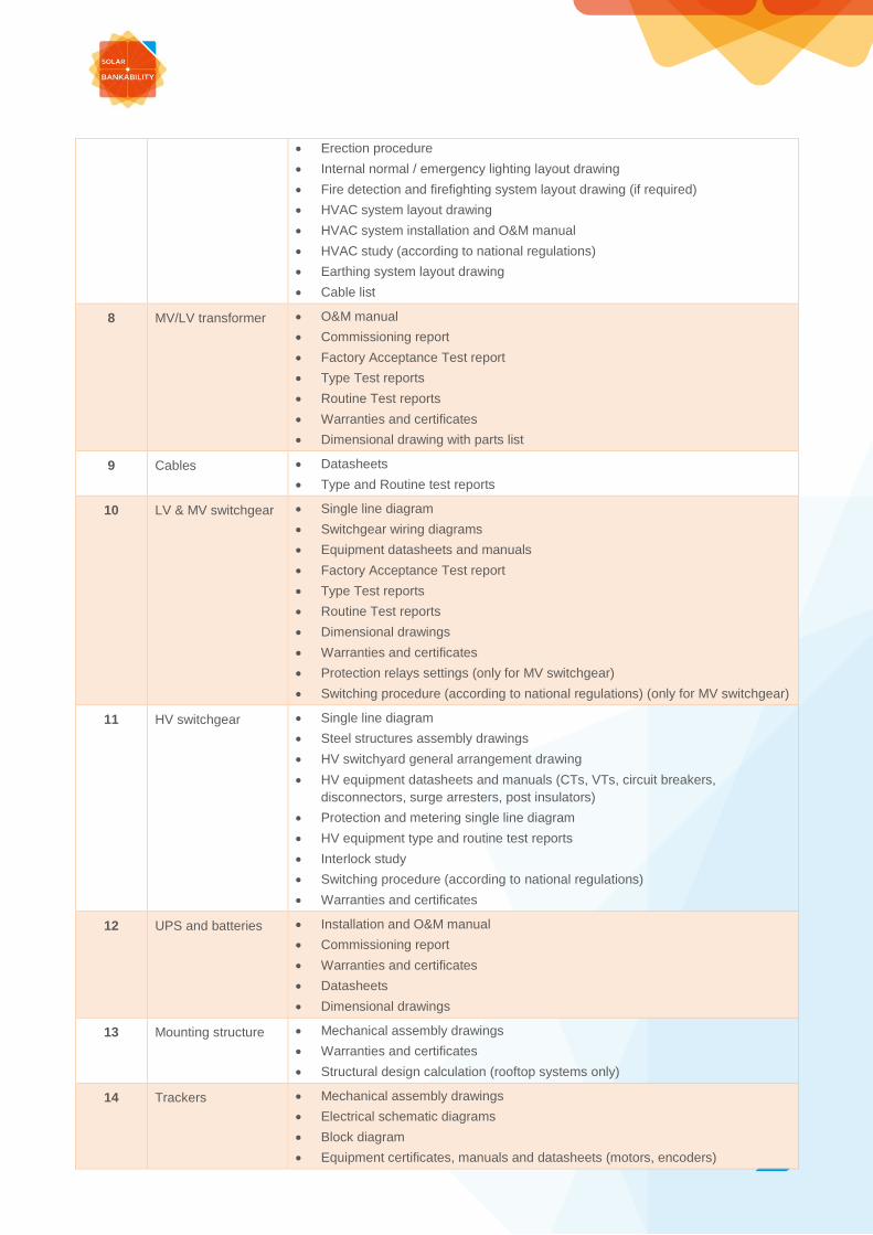
Erection procedure
Internal normal / emergency lighting layout drawing
Fire detection and firefighting system layout drawing (if required)
HVAC system layout drawing
HVAC system installation and O&M manual
HVAC study (according to national regulations)
Earthing system layout drawing
Cable list
8 MV/LV transformer O&M manual
Commissioning report
Factory Acceptance Test report
Type Test reports
Routine Test reports
Warranties and certificates
Dimensional drawing with parts list
9 Cables Datasheets
Type and Routine test reports
10 LV & MV switchgear Single line diagram
Switchgear wiring diagrams
Equipment datasheets and manuals
Factory Acceptance Test report
Type Test reports
Routine Test reports
Dimensional drawings
Warranties and certificates
Protection relays settings (only for MV switchgear)
Switching procedure (according to national regulations) (only for MV switchgear)
11 HV switchgear Single line diagram
Steel structures assembly drawings
HV switchyard general arrangement drawing
HV equipment datasheets and manuals (CTs, VTs, circuit breakers,
disconnectors, surge arresters, post insulators)
Protection and metering single line diagram
HV equipment type and routine test reports
Interlock study
Switching procedure (according to national regulations)
Warranties and certificates
12 UPS and batteries Installation and O&M manual
Commissioning report
Warranties and certificates
Datasheets
Dimensional drawings
13 Mounting structure Mechanical assembly drawings
Warranties and certificates
Structural design calculation (rooftop systems only)
14 Trackers Mechanical assembly drawings
Electrical schematic diagrams
Block diagram
Equipment certificates, manuals and datasheets (motors, encoders)
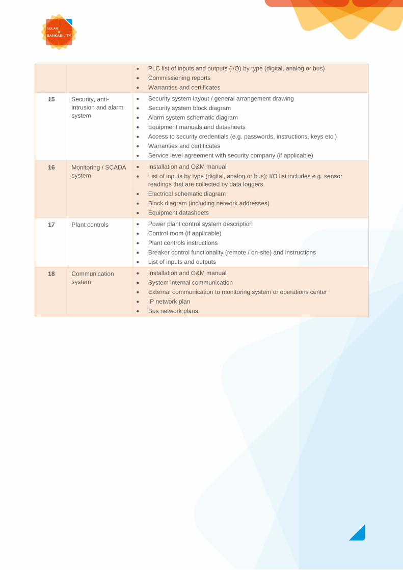
PLC list of inputs and outputs (I/O) by type (digital, analog or bus)
Commissioning reports
Warranties and certificates
15 Security, anti-
intrusion and alarm
system
Security system layout / general arrangement drawing
Security system block diagram
Alarm system schematic diagram
Equipment manuals and datasheets
Access to security credentials (e.g. passwords, instructions, keys etc.)
Warranties and certificates
Service level agreement with security company (if applicable)
16 Monitoring / SCADA
system
Installation and O&M manual
List of inputs by type (digital, analog or bus); I/O list includes e.g. sensor
readings that are collected by data loggers
Electrical schematic diagram
Block diagram (including network addresses)
Equipment datasheets
17 Plant controls Power plant control system description
Control room (if applicable)
Plant controls instructions
Breaker control functionality (remote / on-site) and instructions
List of inputs and outputs
18 Communication
system
Installation and O&M manual
System internal communication
External communication to monitoring system or operations center
IP network plan
Bus network plans
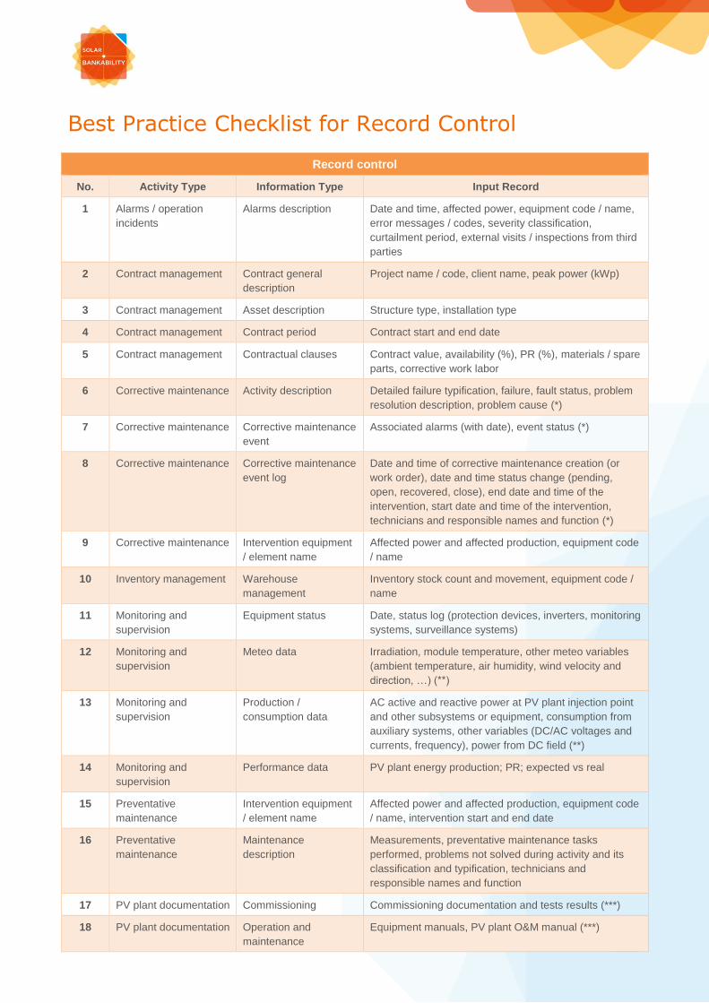
Best Practice Checklist for Record Control
Record control
No. Activity Type Information Type Input Record
1 Alarms / operation
incidents
Alarms description Date and time, affected power, equipment code / name,
error messages / codes, severity classification,
curtailment period, external visits / inspections from third
parties
2 Contract management Contract general
description
Project name / code, client name, peak power (kWp)
3 Contract management Asset description Structure type, installation type
4 Contract management Contract period Contract start and end date
5 Contract management Contractual clauses Contract value, availability (%), PR (%), materials / spare
parts, corrective work labor
6 Corrective maintenance Activity description Detailed failure typification, failure, fault status, problem
resolution description, problem cause (*)
7 Corrective maintenance Corrective maintenance
event
Associated alarms (with date), event status (*)
8 Corrective maintenance Corrective maintenance
event log
Date and time of corrective maintenance creation (or
work order), date and time status change (pending,
open, recovered, close), end date and time of the
intervention, start date and time of the intervention,
technicians and responsible names and function (*)
9 Corrective maintenance Intervention equipment
/ element name
Affected power and affected production, equipment code
/ name
10 Inventory management Warehouse
management
Inventory stock count and movement, equipment code /
name
11 Monitoring and
supervision
Equipment status Date, status log (protection devices, inverters, monitoring
systems, surveillance systems)
12 Monitoring and
supervision
Meteo data Irradiation, module temperature, other meteo variables
(ambient temperature, air humidity, wind velocity and
direction, …) (**)
13 Monitoring and
supervision
Production /
consumption data
AC active and reactive power at PV plant injection point
and other subsystems or equipment, consumption from
auxiliary systems, other variables (DC/AC voltages and
currents, frequency), power from DC field (**)
14 Monitoring and
supervision
Performance data PV plant energy production; PR; expected vs real
15 Preventative
maintenance
Intervention equipment
/ element name
Affected power and affected production, equipment code
/ name, intervention start and end date
16 Preventative
maintenance
Maintenance
description
Measurements, preventative maintenance tasks
performed, problems not solved during activity and its
classification and typification, technicians and
responsible names and function
17 PV plant documentation Commissioning Commissioning documentation and tests results (***)
18 PV plant documentation Operation and
maintenance
Equipment manuals, PV plant O&M manual (***)

19 PV plant documentation System documentation As built documentation (datasheets, wiring diagrams,
system data) (***)
20 Warranty management Claims registration Affected equipment, claim description, occurrence date,
communications between O&M, client and
manufacturer/supplier
21 Security management Alarm intervention Alarms log, type of alarm, time of occurrence, counter
measures
(*) EN 13306 - Maintenance. Maintenance terminology
(**) IEC 61724 - Photovoltaic system performance monitoring - Guidelines for measurement, data exchange and analysis
(***) IEC 62446 - Photovoltaic (PV) systems - Requirements for testing, documentation and maintenance - Part 1: Grid
connected systems - Documentation, commissioning tests and inspection
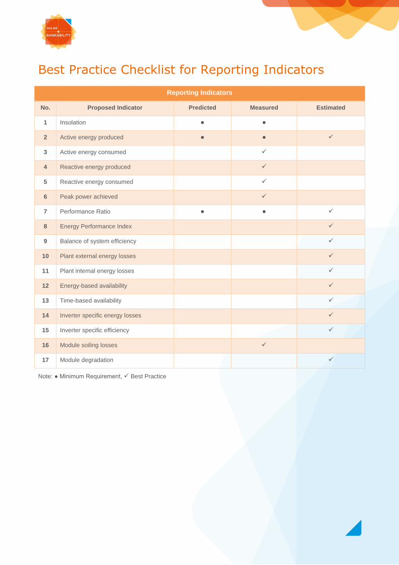
Best Practice Checklist for Reporting Indicators
Reporting Indicators
No. Proposed Indicator Predicted Measured Estimated
1 Insolation ● ●
2 Active energy produced ● ●
3 Active energy consumed
4 Reactive energy produced
5 Reactive energy consumed
6 Peak power achieved
7 Performance Ratio ● ●
8 Energy Performance Index
9 Balance of system efficiency
10 Plant external energy losses
11 Plant internal energy losses
12 Energy-based availability
13 Time-based availability
14 Inverter specific energy losses
15 Inverter specific efficiency
16 Module soiling losses
17 Module degradation
Note: ● Minimum Requirement, Best Practice