
Best Practice Catalog
20
Best Practice Catalog Main Power Transformer Revision 1.0, 12/08/2011
Transcript of Best Practice Catalog
Best Practice Catalog
Main Power Transformer
Revision 1.0, 12/08/2011
HAP – Best Practice Catalog – Main Power Transformer
Rev. 1.0, 12/08/2011 2
Prepared by
MESA ASSOCIATES, INC.
Chattanooga, TN 37402
and
OAK RIDGE NATIONAL LABORATORY
Oak Ridge, Tennessee 37831-6283
managed by
UT-BATTELLE, LLC
for the
U.S. DEPARTMENT OF ENERGY
under contract DE-AC05-00OR22725

HAP – Best Practice Catalog – Main Power Transformer
Rev. 1.0, 12/08/2011 3
Contents 1.0 Scope and Purpose ............................................................................................................... 4
1.1 Hydropower Taxonomy Position ..................................................................................... 4
1.1.1 Main Power Transformer Components ........................................................................ 4
1.2 Summary of Best Practices .............................................................................................. 6
1.2.1 Performance / Efficiency & Capability - Oriented Best Practices ............................... 6
1.2.2 Reliability / Operations & Maintenance - Oriented Best Practices .............................. 6
1.3 Best Practice Cross-references ......................................................................................... 7
2.0 Technology Design Summary .............................................................................................. 7
2.1 Material and Design Technology Evolution .................................................................... 7
2.2 State of the Art Technology ............................................................................................. 9
3.0 Operation & Maintenance Practices .................................................................................. 10
3.1 Condition Assessment .................................................................................................... 10
3.2 Operations ...................................................................................................................... 12
3.3 Maintenance ................................................................................................................... 13
4.0 Metrics, Monitoring and Analysis ..................................................................................... 17
4.1 Measures of Performance, Condition, and Reliability ................................................... 17
4.2 Integrate Improvements.................................................................................................. 18
5.0 Information Sources: .......................................................................................................... 19
HAP – Best Practice Catalog – Main Power Transformer
Rev. 1.0, 12/08/2011 4
1.0 Scope and Purpose
This best practice for the Main Power Transformer (MPT) discusses design components,
condition assessment, operations, and maintenance best practices with the objective to maximize
overall plant performance and reliability.
The primary purpose of the main power transformer is to step up the generator output to a higher
voltage for efficient transmission of energy. The MPT is a critical component of any generation
station. As the MPT connects the generator to the transmission grid, the output of the generator is
directly dependent on the availability and operational status of the transformer. Thermal and
electrical limits of the transformer must be considered in the plant operation. Proper design,
operation, and maintenance are required to provide the utmost efficiency, performance and
reliability of the hydro unit.
1.1 Hydropower Taxonomy Position
Hydropower Facility → Powerhouse → Power Train Equipment → Transformer
1.1.1 Main Power Transformer Components
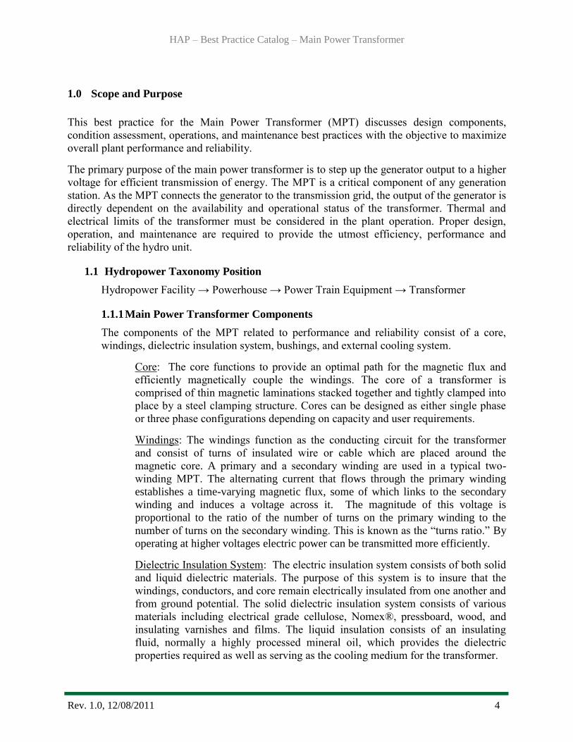
The components of the MPT related to performance and reliability consist of a core,
windings, dielectric insulation system, bushings, and external cooling system.
Core: The core functions to provide an optimal path for the magnetic flux and
efficiently magnetically couple the windings. The core of a transformer is
comprised of thin magnetic laminations stacked together and tightly clamped into
place by a steel clamping structure. Cores can be designed as either single phase
or three phase configurations depending on capacity and user requirements.
Windings: The windings function as the conducting circuit for the transformer
and consist of turns of insulated wire or cable which are placed around the
magnetic core. A primary and a secondary winding are used in a typical two-
winding MPT. The alternating current that flows through the primary winding
establishes a time-varying magnetic flux, some of which links to the secondary
winding and induces a voltage across it. The magnitude of this voltage is
proportional to the ratio of the number of turns on the primary winding to the
number of turns on the secondary winding. This is known as the “turns ratio.” By
operating at higher voltages electric power can be transmitted more efficiently.
Dielectric Insulation System: The electric insulation system consists of both solid
and liquid dielectric materials. The purpose of this system is to insure that the
windings, conductors, and core remain electrically insulated from one another and
from ground potential. The solid dielectric insulation system consists of various
materials including electrical grade cellulose, Nomex®, pressboard, wood, and
insulating varnishes and films. The liquid insulation consists of an insulating
fluid, normally a highly processed mineral oil, which provides the dielectric
properties required as well as serving as the cooling medium for the transformer.
HAP – Best Practice Catalog – Main Power Transformer
Rev. 1.0, 12/08/2011 5
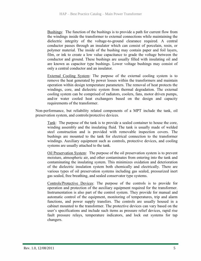
Bushings: The function of the bushings is to provide a path for current flow from
the windings inside the transformer to external connections while maintaining the
dielectric integrity of the voltage-to-ground clearance required. A central
conductor passes through an insulator which can consist of porcelain, resin, or
polymer material. The inside of the bushing may contain paper and foil layers,
film, or ink to create a low value capacitance to grade the voltage between the
conductor and ground. These bushings are usually filled with insulating oil and
are known as capacitor type bushings. Lower voltage bushings may consist of
only a central conductor and an insulator.
External Cooling System: The purpose of the external cooling system is to
remove the heat generated by power losses within the transformers and maintain
operation within design temperature parameters. The removal of heat protects the
windings, core, and dielectric system from thermal degradation. The external
cooling system can be comprised of radiators, coolers, fans, motor driven pumps,
and/or water cooled heat exchangers based on the design and capacity
requirements of the transformer.
Non-performance, but reliability related components of a MPT include the tank, oil
preservation system, and controls/protective devices.
Tank: The purpose of the tank is to provide a sealed container to house the core,
winding assembly and the insulating fluid. The tank is usually made of welded
steel construction and is provided with removable inspection covers. The
bushings are mounted to the tank for electrical connection to the transformer
windings. Auxiliary equipment such as controls, protective devices, and cooling
systems are usually attached to the tank.
Oil Preservation System: The purpose of the oil preservation system is to prevent
moisture, atmospheric air, and other contaminates from entering into the tank and
contaminating the insulating system. This minimizes oxidation and deterioration
of the dielectric insulation system both chemically and electrically. There are
various types of oil preservation systems including gas sealed, pressurized inert
gas sealed, free breathing, and sealed conservator type systems.
Controls/Protective Devices: The purpose of the controls is to provide for
operation and protection of the auxiliary equipment required for the transformer.
Instrumentation is also part of the control system. They provide for manual and
automatic control of the equipment, monitoring of temperatures, trip and alarm
functions, and power supply transfers. The controls are usually housed in a
cabinet mounted to the transformer. The protective devices can vary based on the
user’s specifications and include such items as pressure relief devices, rapid rise
fault pressure relays, temperature indicators, and lock out systems for tap
changers.
HAP – Best Practice Catalog – Main Power Transformer
Rev. 1.0, 12/08/2011 6
1.2 Summary of Best Practices
1.2.1 Performance / Efficiency & Capability - Oriented Best Practices
Routine testing to verify performance within the original design criteria and
factory test baseline data.
Real-time monitoring and analysis of transformer performance at Current
Performance Level (CPL) to detect and mitigate deviations from design
parameters for the Installed Performance Level (IPL) due to system degradation,
thermal issues, or malfunction of instrumentation.
Periodic comparison of the CPL to the Potential Performance Level (PPL) to
trigger feasibility studies of major upgrades or replacement opportunities.
Maintain documentation of IPL and update if major modifications are performed
(e.g., winding replacement, cooling system upgrades, oil reclamation).
Periodic comparison of the CPL to the IPL to monitor deterioration and trigger
maintenance or repair. This is especially important regarding routine field
electrical test results.
Trend transformer performance and test data for early detection of deterioration,
contamination, thermal degradation, and incipient faults.
Include industry acknowledged choices and experience for transformer design,
replacement components, and maintenance practices to plant engineering
standards.
1.2.2 Reliability / Operations & Maintenance - Oriented Best Practices
Establish a comprehensive dissolved gas-in-oil analysis (DGA) testing program to
monitor the internal health of the transformer. Accurate analysis and trending of
analytical data can provide early detection of thermal and electrical incipient
faults and allow for intervention and mitigation measures.
Maintain an insulating oil quality testing program to monitor the chemical and
electrical condition of the insulating fluid. Degradation of the insulating fluid
leads to degradation of the solid insulation system which can lead to failure. The
life of the insulation system is the life of the transformer.
Implement a routine electrical testing program and track and trend critical data.
Establish action limits to correct defects found prior to placing the transformer
back in-service.
Insure operation of the MPT within its design voltage limits, typically 105%
maximum to avoid damaging over-excitation issues. Adequate voltage taps should
be provided to adjust to any feasible system condition to prevent this situation.
HAP – Best Practice Catalog – Main Power Transformer
Rev. 1.0, 12/08/2011 7
Operate the transformer within its thermal design limits to prevent accelerated
thermal aging and damage to the insulation system and bushings.
Investigate all oil or nitrogen leaks and determine the need and priority for repair.
Maintain the cooling and oil preservation system with a preventative maintenance
program as these systems protect the transformer from damaging heat, moisture,
and atmospheric air.
Trend bushing condition and replace when significant deterioration is indicated by
comparing all test values to individual bushing nameplate data.
Recondition or reclaim insulating oil when trend analysis indicates need.
Test and calibrate controls and indicating devices and upgrade when required.
Insure availability of on-site or system wide spare transformer(s) and spare parts
to reduce the forced outage time incurred with a failure.
Monitor for trends of deteriorating condition of the transformer (decrease in
Condition Indicator (CI)) and decrease in reliability (an increase in Equivalent
Forced Outage Rate (EFOR), a decrease in Effective Availability Factor (EAF).
Adjust maintenance and capitalization programs to correct deficiencies.
1.3 Best Practice Cross-references
I&C - Automation Best Practice
2.0 Technology Design Summary
2.1 Material and Design Technology Evolution
Transformers have changed very little since their inception with regard to their functionality.
The principal change is the efficiency and performance of modern core designs and improved
windings and insulation materials. Modern transformers are smaller, have higher thermal
limits and fewer losses than the older transformer fleet. Advancements in core materials,
winding design and maintenance innovations have improved efficiency and reliability
significantly.
Performance levels for MPT designs can be stated at three levels as follows:
The Installed Performance Level (IPL) is described by the transformers performance
characteristics at the time of installation. These may be determined from factory
reports and baseline field test comparisons performed prior to initially placing the
transformer in-service.
HAP – Best Practice Catalog – Main Power Transformer
Rev. 1.0, 12/08/2011 8
The Current Performance Level (CPL) is determined by an accurate analysis of the
transformers operating characteristics. These would include thermal performance at
full load as well as component condition or test deviations discovered.
Determination of the Potential Performance Level (PPL) typically requires interface
with vendors for new transformer design, loss information, and cost in order to
evaluate the achievable performance potential of replacement transformer(s).
Transformer efficiency is primarily determined by the original design criteria.
Incremental efficiency improvements may be accomplished by system upgrades, but
winding and core replacement are often not cost effective for very old transformers. The
transformers insulation condition and age are among the top factors in an assessment to
determine whether the MPT is a candidate for replacement or rehabilitation.
Analysis of operational history and test data may indicate that the CPL has significantly
deviated from the IPL. Increased maintenance and operational constraints are also used to
determine the CPL.
Many older transformers were more liberally designed and losses were not evaluated as
critically as today. These losses can be significantly higher than those of a modern
transformer. Losses associated with the MPT can be grouped into three major categories.
Load losses
No-load losses
Auxiliary losses
The load losses are the largest of the three followed by the no-load losses. The auxiliary
losses are comparatively quite small. For example, typical losses for a 36 year old MPT
rated 161-13.2-kV, 58,500/78,000/87,300 kva, three phase, 55oC/65
oC rise,
ONAN/ONAF are:
Load losses 212.57 kW at rated current
No-load losses 56.07 kW at 100% rated voltage
Auxiliary losses 3 kW with all fans in operation
The load losses are associated with the windings and primarily consist of:
I2R loss associated with current
Eddy current loss in the winding conductors
Advanced technology in winding conductor arrangements, transposition, and materials
are used today in modern designs to reduce these losses. As the name implies, these
losses are governed by the load current carried by the transformer and the resistance of
the windings.
HAP – Best Practice Catalog – Main Power Transformer
Rev. 1.0, 12/08/2011 9
The no-load losses are associated with the core but independent of the load for the most
part, and they are incurred whenever the transformer is energized. These losses are
primarily the result of:
Excitation current
Hysteresis loss
Eddy currents
The auxiliary losses are associated primarily with the cooling system and are incurred by
the pump motors and fan motors and are usually negligible in comparison to load and no-
load losses.
2.2 State of the Art Technology
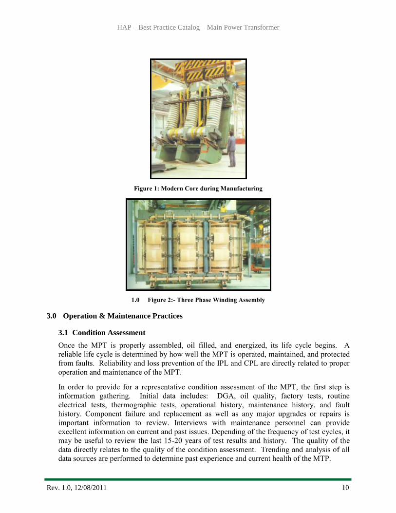
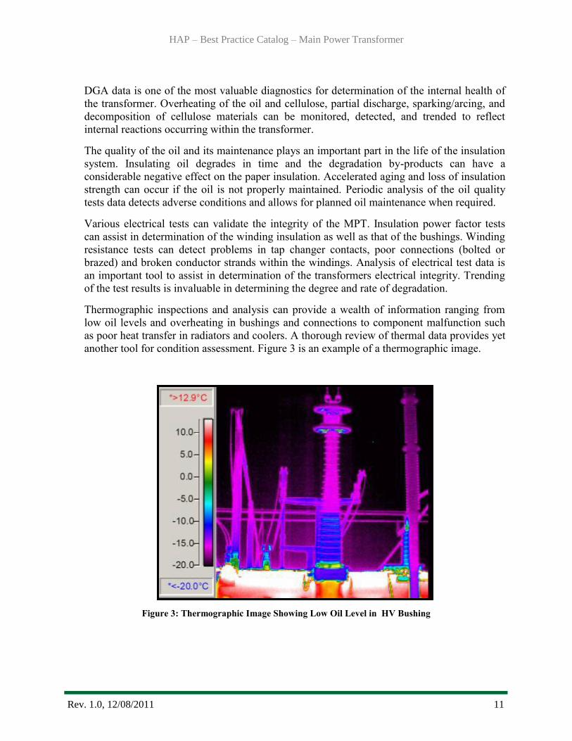
More efficient material and manufacturing techniques have been developed over the
years to reduce the no-load losses. Modern transformer designers can utilize various
grades of steel for the core laminations. Fabrication techniques such as laser etching were
not available years ago. Improved core assembly and configuration processes are also
utilized in modern transformers. Figure 1 shows an example of a modern core in a
manufacturing facility. Figure 2 illustrates a 3-phase winding assembly before installation
in the tank.
Advancements in instrumentation and controls can now provide for more efficient and
reliable monitoring of the transformer and associated systems. These include fiber optics
for actual winding conductor temperature, bearing wear monitors for motor driven oil
pumps, partial discharge probes, and on-line bushing monitors.
Replacement of aged MPT’s with modern state of the art designs may result in significant
reduction of losses as compared to those of 40-50 year old transformers. The cost savings
should be considered for the life cycle of a new transformer and decisions should not be
based solely on initial costs. Additionally, establishing partnering agreements with
manufacturers and developing standardized designs can result in substantial cost savings
in the purchase cost of replacement transformers and reduce inventory of spare parts.
HAP – Best Practice Catalog – Main Power Transformer
Rev. 1.0, 12/08/2011 10
Figure 1: Modern Core during Manufacturing
1.0 Figure 2:- Three Phase Winding Assembly
3.0 Operation & Maintenance Practices
3.1 Condition Assessment
Once the MPT is properly assembled, oil filled, and energized, its life cycle begins. A
reliable life cycle is determined by how well the MPT is operated, maintained, and protected
from faults. Reliability and loss prevention of the IPL and CPL are directly related to proper
operation and maintenance of the MPT.
In order to provide for a representative condition assessment of the MPT, the first step is
information gathering. Initial data includes: DGA, oil quality, factory tests, routine
electrical tests, thermographic tests, operational history, maintenance history, and fault
history. Component failure and replacement as well as any major upgrades or repairs is
important information to review. Interviews with maintenance personnel can provide
excellent information on current and past issues. Depending of the frequency of test cycles, it
may be useful to review the last 15-20 years of test results and history. The quality of the
data directly relates to the quality of the condition assessment. Trending and analysis of all
data sources are performed to determine past experience and current health of the MTP.
HAP – Best Practice Catalog – Main Power Transformer
Rev. 1.0, 12/08/2011 11
DGA data is one of the most valuable diagnostics for determination of the internal health of
the transformer. Overheating of the oil and cellulose, partial discharge, sparking/arcing, and
decomposition of cellulose materials can be monitored, detected, and trended to reflect
internal reactions occurring within the transformer.
The quality of the oil and its maintenance plays an important part in the life of the insulation
system. Insulating oil degrades in time and the degradation by-products can have a
considerable negative effect on the paper insulation. Accelerated aging and loss of insulation
strength can occur if the oil is not properly maintained. Periodic analysis of the oil quality
tests data detects adverse conditions and allows for planned oil maintenance when required.
Various electrical tests can validate the integrity of the MPT. Insulation power factor tests
can assist in determination of the winding insulation as well as that of the bushings. Winding
resistance tests can detect problems in tap changer contacts, poor connections (bolted or
brazed) and broken conductor strands within the windings. Analysis of electrical test data is
an important tool to assist in determination of the transformers electrical integrity. Trending
of the test results is invaluable in determining the degree and rate of degradation.
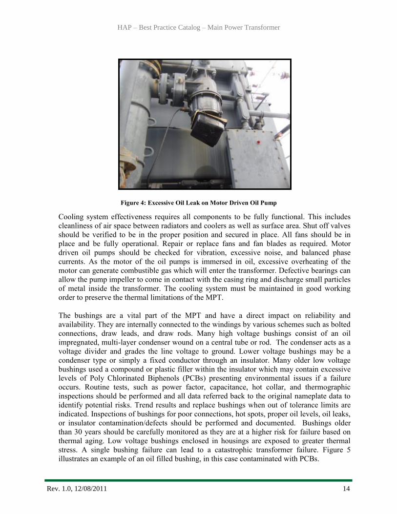
Thermographic inspections and analysis can provide a wealth of information ranging from
low oil levels and overheating in bushings and connections to component malfunction such
as poor heat transfer in radiators and coolers. A thorough review of thermal data provides yet
another tool for condition assessment. Figure 3 is an example of a thermographic image.
Figure 3: Thermographic Image Showing Low Oil Level in HV Bushing

HAP – Best Practice Catalog – Main Power Transformer
Rev. 1.0, 12/08/2011 12
The age of the transformer must be considered as it relates to the condition of the insulation
system. In the presence of heat, moisture, and oxygen, all cellulose insulation systems will
deteriorate. The insulation strength will weaken until the system cannot adequately perform
its intended electrical function. Even with excellent maintenance these three entities can be
minimized, but not entirely eliminated. Replacement of the entire insulation system for a 35-
40 year old transformer is not economically feasible. Age plays an important factor in the
condition assessment of MPT’s.
After or during the data process, a physical inspection of the MPT is necessary in order to
form a current impression of the equipment and discover any existing anomalies. Nameplate
information can be obtained during the inspection. A systematic inspection process for the
condition assessment should be performed to include the main tank, cooling system,
bushings, oil preservation system, tap changer, controls, and protective/indicating devices.
Upon completion of the data assessment and physical inspection, a systematic and consistent
approach should be used for each MPT. This allows some prioritization to be assigned to
each MPT for ranking purposes which assists in developing a plan for rehabilitation or
replacement options assisting in both short term and long term strategic planning.
3.2 Operations
The MPTs operational parameters are governed by the original design criteria. Operation
within these parameters provides the most efficient performance of the equipment and
provides for optimum service life.
All transformers have thermal limits that must be strictly observed in order to maximize the
life of the transformer. These temperature rise ratings are typically 55oC for standard
cellulose insulation or 65oC for thermally upgraded cellulose. These temperature rise ratings
are based on a 30oC ambient. These ratings also determine the set points for the first and
second stage cooling equipment if provided. Elevated operating temperatures above design
ratings will cause excessive deterioration of the insulation system. For every 10oC increase in
windings hot spot temperature above the design, the solid insulations reliable service life is
cut in half. Thermal decomposition is cumulative and the life of the transformer is the life of
the insulation system.
The MPTs capacity must equal or exceed that of the generator output. This is determined
during design and any anticipated future uprates to the generator need to be considered when
initially sizing the transformer. Sustained overloading can have significantly adverse
consequences and cause damage to the windings, core, and insulation system. Overloading
can also cause excessive temperature rise to occur in sealed bushings and lead to failure. The
MPT should be operated within its design capacity in order to maximize the service life,
The maximum continuous operating voltage as governed by ANSI C84.1-1995 and IEEE
C57.1200 is 105% continuous secondary voltage at rated MVA and at a power factor not less
than 0.8. The system conditions may require tap changer adjustments higher than the system
voltage for regulation purposes. The primary voltage must be carefully maintained by the
generator so as not to over excite the primary winding. Over excitation will allow the

HAP – Best Practice Catalog – Main Power Transformer
Rev. 1.0, 12/08/2011 13
excitation current to increase exponentially and core saturation can occur leading to damage
to the transformer.
Modern surge arresters should be used to protect the transformer from close in faults. Metal
oxide surge arresters provide better protection than the older thyrite type. A best practice is to
have the arresters mounted as close to the bushing terminals as practical. Most modern
designs now mount the arrester assembly to the transformer tank.
Plants should, as a good practice, carefully monitor the transformers operational data and
insure that strict controls are in place to prevent operation of the MPT beyond its intended
design.
Provisions for spare transformers greatly enhance unit availability by providing “insurance”
when a failure occurs. Major repairs or replacement of an MPT can be a costly and lengthy
process and on-site spare transformers can significantly improve the availability factor for the
unit when a major event occurs.
Utilization of fixed fire protection and oil containment systems can also reduce collateral
damage and minimize environmental issues during a major failure event and should be
considered as a good practice.
3.3 Maintenance
Preventative and corrective maintenance are essential components of any MPT. The demand
for timely maintenance becomes more critical as the transformer ages. Routine maintenance
of the various transformer components is vital to the life of any power transformer regardless
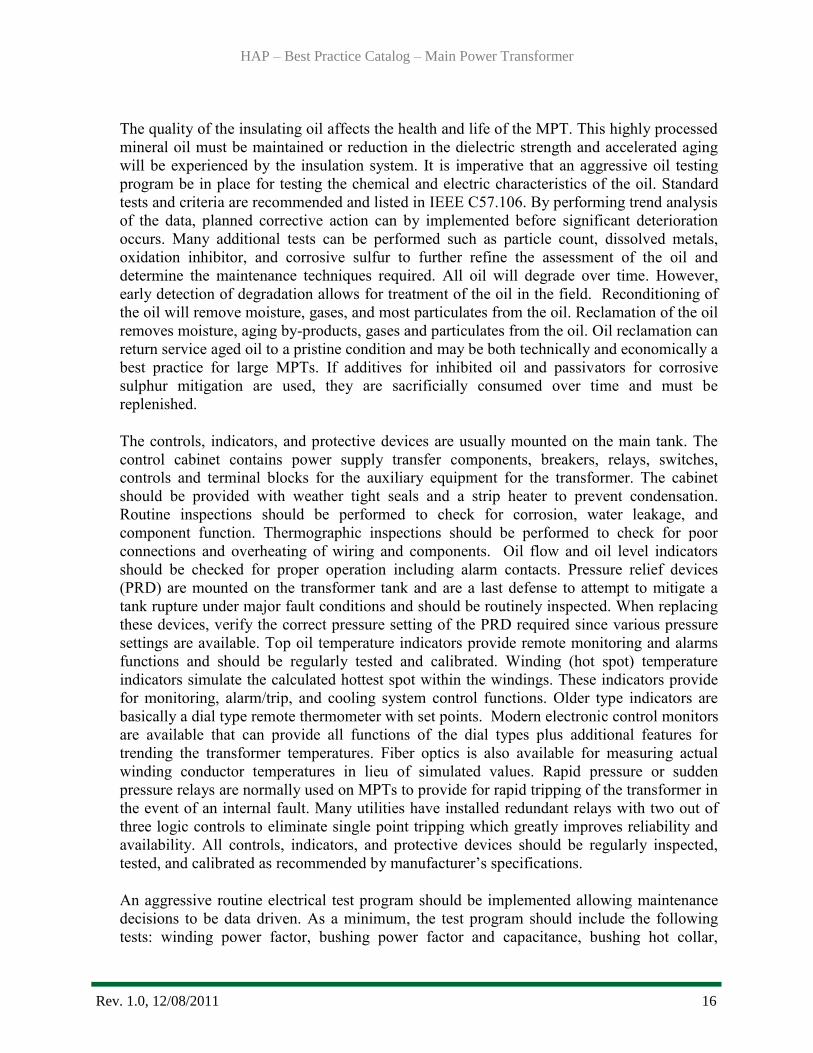
of its age. An example of a typical maintenance issue would involve the inspection of the
main tank. It should be inspected for oil leaks, rust, and effectiveness of the paint system. All
gasketed flanges, mounting plates, bushing turrets, manhole covers, fittings, and valves
should be inspected and oil leaks documented. Some oil leaks discovered may have severe
consequences if not corrected. For instance, oil leakage on the intake side of a motor driven
oil pump or flange can draw atmospheric air bubbles into the transformer. Bubble formation
can be extremely detrimental to the electrical integrity of the transformer. Oil leaks should be
corrected to address potential reliability and environmental concerns. Any unusual or
excessive noise or vibration should be thoroughly investigated to determine source. Figure 4
illustrates remedial measures to mitigate an oil pump leak. Such measures are not
recommended as a long-term repair.
HAP – Best Practice Catalog – Main Power Transformer
Rev. 1.0, 12/08/2011 14
Figure 4: Excessive Oil Leak on Motor Driven Oil Pump
Cooling system effectiveness requires all components to be fully functional. This includes
cleanliness of air space between radiators and coolers as well as surface area. Shut off valves
should be verified to be in the proper position and secured in place. All fans should be in
place and be fully operational. Repair or replace fans and fan blades as required. Motor
driven oil pumps should be checked for vibration, excessive noise, and balanced phase
currents. As the motor of the oil pumps is immersed in oil, excessive overheating of the
motor can generate combustible gas which will enter the transformer. Defective bearings can
allow the pump impeller to come in contact with the casing ring and discharge small particles
of metal inside the transformer. The cooling system must be maintained in good working
order to preserve the thermal limitations of the MPT.
The bushings are a vital part of the MPT and have a direct impact on reliability and
availability. They are internally connected to the windings by various schemes such as bolted
connections, draw leads, and draw rods. Many high voltage bushings consist of an oil
impregnated, multi-layer condenser wound on a central tube or rod. The condenser acts as a
voltage divider and grades the line voltage to ground. Lower voltage bushings may be a
condenser type or simply a fixed conductor through an insulator. Many older low voltage
bushings used a compound or plastic filler within the insulator which may contain excessive
levels of Poly Chlorinated Biphenols (PCBs) presenting environmental issues if a failure
occurs. Routine tests, such as power factor, capacitance, hot collar, and thermographic
inspections should be performed and all data referred back to the original nameplate data to
identify potential risks. Trend results and replace bushings when out of tolerance limits are
indicated. Inspections of bushings for poor connections, hot spots, proper oil levels, oil leaks,
or insulator contamination/defects should be performed and documented. Bushings older
than 30 years should be carefully monitored as they are at a higher risk for failure based on
thermal aging. Low voltage bushings enclosed in housings are exposed to greater thermal
stress. A single bushing failure can lead to a catastrophic transformer failure. Figure 5
illustrates an example of an oil filled bushing, in this case contaminated with PCBs.

HAP – Best Practice Catalog – Main Power Transformer
Rev. 1.0, 12/08/2011 15
Figure 5: PCB Contaminated Bushings
The oil preservation system keeps external contaminates such as atmospheric air and
moisture from entering the transformer. This protects both the liquid and solid insulation
system. Oxidation of the oil is minimized and ingress of moisture is prevented. Preserving
the oil quality is paramount to maximizing the life of the insulation system. A number of
different type systems are used including sealed inert gas, inert gas constant positive
pressure, free breathing, and sealed conservator. The function and operation of each type
system used should be thoroughly understood in order to perform proper maintenance.
The two most common types of sealed tanks used on modern transformers in the U.S. are
pressurized inert gas sealed and sealed conservator. The inert gas constant positive pressure
sealed system (often referred to as nitrogen blanketed) maintains positive pressure of dry
inert gas, usually nitrogen, above the oil. A nitrogen bottle and regulator system maintains a
positive pressure of 0.5 to 5.0 PSI above the oil. The nitrogen used should meet ASTM D-
1993 Type III with a -59oC dew point as specified in IEEE C-57.12.00. Regular inspection
should be performed of the high pressure gauge, high/low pressure regulators, valves,
pressure vacuum bleeder, and oil sump. Never allow the tank pressure be zero or negative
pressure. The sealed conservator system uses an expansion tank (conservator) which is
mounted above the main tank and maintains the oil at atmospheric pressure. An air cell or
diaphragm is placed inside the conservator which is vented through a silica gel breather. As
the oil in the main tank expands and contracts within the conservator, the transformer
“breathes” to atmosphere via the breather. The air cell or diaphragm serves as a barrier and
prevents any external air or other contaminates from coming into contact with the oil. The
silica gel breather dries the air entering the conservator and the indicating silica gel should be
inspected regularly and the desiccant replaced when approximately one-half of the material
changes color. The inspection port on top of the conservator should be removed every 5-6
years and the inside of the air cell or diaphragm inspected. If any oil is observed, a leak has
developed, and the cell or diaphragm must be replaced. The quality of the insulating oil is
highly dependent on proper maintenance of this system.
HAP – Best Practice Catalog – Main Power Transformer
Rev. 1.0, 12/08/2011 16
The quality of the insulating oil affects the health and life of the MPT. This highly processed
mineral oil must be maintained or reduction in the dielectric strength and accelerated aging
will be experienced by the insulation system. It is imperative that an aggressive oil testing
program be in place for testing the chemical and electric characteristics of the oil. Standard
tests and criteria are recommended and listed in IEEE C57.106. By performing trend analysis
of the data, planned corrective action can by implemented before significant deterioration
occurs. Many additional tests can be performed such as particle count, dissolved metals,
oxidation inhibitor, and corrosive sulfur to further refine the assessment of the oil and
determine the maintenance techniques required. All oil will degrade over time. However,
early detection of degradation allows for treatment of the oil in the field. Reconditioning of
the oil will remove moisture, gases, and most particulates from the oil. Reclamation of the oil
removes moisture, aging by-products, gases and particulates from the oil. Oil reclamation can
return service aged oil to a pristine condition and may be both technically and economically a
best practice for large MPTs. If additives for inhibited oil and passivators for corrosive
sulphur mitigation are used, they are sacrificially consumed over time and must be
replenished.
The controls, indicators, and protective devices are usually mounted on the main tank. The
control cabinet contains power supply transfer components, breakers, relays, switches,
controls and terminal blocks for the auxiliary equipment for the transformer. The cabinet
should be provided with weather tight seals and a strip heater to prevent condensation.
Routine inspections should be performed to check for corrosion, water leakage, and
component function. Thermographic inspections should be performed to check for poor
connections and overheating of wiring and components. Oil flow and oil level indicators
should be checked for proper operation including alarm contacts. Pressure relief devices
(PRD) are mounted on the transformer tank and are a last defense to attempt to mitigate a
tank rupture under major fault conditions and should be routinely inspected. When replacing
these devices, verify the correct pressure setting of the PRD required since various pressure
settings are available. Top oil temperature indicators provide remote monitoring and alarms
functions and should be regularly tested and calibrated. Winding (hot spot) temperature
indicators simulate the calculated hottest spot within the windings. These indicators provide
for monitoring, alarm/trip, and cooling system control functions. Older type indicators are
basically a dial type remote thermometer with set points. Modern electronic control monitors
are available that can provide all functions of the dial types plus additional features for
trending the transformer temperatures. Fiber optics is also available for measuring actual
winding conductor temperatures in lieu of simulated values. Rapid pressure or sudden
pressure relays are normally used on MPTs to provide for rapid tripping of the transformer in
the event of an internal fault. Many utilities have installed redundant relays with two out of
three logic controls to eliminate single point tripping which greatly improves reliability and
availability. All controls, indicators, and protective devices should be regularly inspected,
tested, and calibrated as recommended by manufacturer’s specifications.
An aggressive routine electrical test program should be implemented allowing maintenance
decisions to be data driven. As a minimum, the test program should include the following
tests: winding power factor, bushing power factor and capacitance, bushing hot collar,
HAP – Best Practice Catalog – Main Power Transformer
Rev. 1.0, 12/08/2011 17
winding resistance, excitation, core ground insulation resistance (if external), and insulation
resistance. Thermographic inspections should be included within the test program. All data
analysis should be referred back to base line commission and/or factory and nameplate data.
Additional advanced testing may be performed such as sweep frequency response analysis,
acoustical and partial discharge tests when indicated.
The spare transformer(s) should be maintained in fully operational condition and should
always be immediately available. Components should not be removed and used as spare parts
for other MPTs. When the spare is needed, it is usually installed under tight time constraints.
Routine testing and inspections should be performed in the same manner as an operating
transformer. Adequate critical spare parts such as bushings should be immediately available.
4.0 Metrics, Monitoring and Analysis
4.1 Measures of Performance, Condition, and Reliability
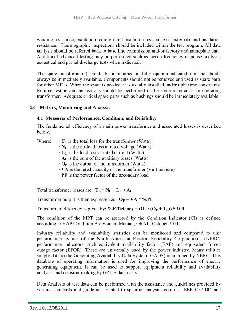
The fundamental efficiency of a main power transformer and associated losses is described
below.
Where: · TL is the total loss for the transformer (Watts)
· NL is the no-load loss at rated voltage (Watts)
· LL is the load loss at rated current (Watts)
· AL is the sum of the auxiliary losses (Watts)
· OP is the output of the transformer (Watts)
· VA is the rated capacity of the transformer (Volt-ampere)
· PF is the power factor of the secondary load
Total transformer losses are: TL = NL + LL + AL
Transformer output is then expressed as: OP = VA * %PF
Transformer efficiency is given by: %Efficiency = (OP / (OP + TL)) * 100
The condition of the MPT can be assessed by the Condition Indicator (CI) as defined
according to HAP Condition Assessment Manual, ORNL, October 2011.
Industry reliability and availability statistics can be monitored and compared to unit
performance by use of the North American Electric Reliability Corporation’s (NERC)
performance indicators, such equivalent availability factor (EAF) and equivalent forced
outage factor (EFOR). These are universally used by the power industry. Many utilities
supply data to the Generating Availability Data System (GADS) maintained by NERC. This
database of operating information is used for improving the performance of electric
generating equipment. It can be used to support equipment reliability and availability
analyses and decision-making by GADS data users.
Data Analysis of test data can be performed with the assistance and guidelines provided by
various standards and guidelines related to specific analysis required. IEEE C57.104 and
HAP – Best Practice Catalog – Main Power Transformer
Rev. 1.0, 12/08/2011 18
C57.106 standards provide information for testing and analysis of insulating oil. Various
ASTM standards provide testing procedures and methodology. Several companies offer
valuable electrical testing, oil analysis and investigation resources and provides assistance on
interpretation and analysis techniques. Many vendor and reference materials are also
available on all aspects of power transformers.
Determine the MPTs existing capabilities (CPL) and compare results to previous or original
test data (IPL). Assess the efficiency, reliability, capacity needs, transformer energy losses,
and revenue loss. Compare results to new MPT design data (from transformer manufacturer),
and determine potential efficiency, capacity, annual energy loss savings, and revenue gain
(PPL). For the latter, calculate the installation/rehabilitation cost and internal rate of return to
determine major upgrade or replacement justification.
The condition assessment of the MPT is quantified through the CI as derived according to
HAP Condition Assessment Manual, ORNL, October 2011. The overall CI is a composite of
the CI derived from each component of the transformer. This methodology can be applied
periodically to monitor existing transformer and can be monitored and analyzed over time to
determine condition trends that can impact performance and reliability.
The reliability of a unit as judged by its availability to generate can be monitored through
reliability indexes or performance indicators as derived according to NERC’s Appendix F,
Performance Indexes and Equations.
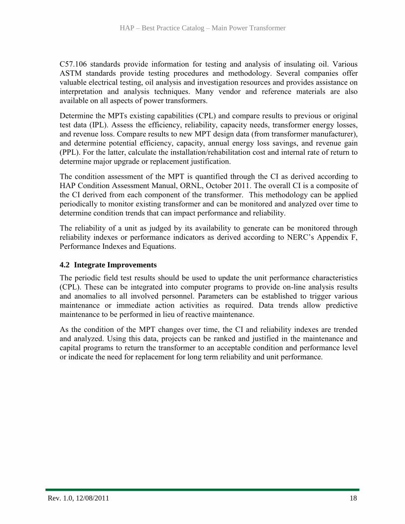
4.2 Integrate Improvements
The periodic field test results should be used to update the unit performance characteristics
(CPL). These can be integrated into computer programs to provide on-line analysis results
and anomalies to all involved personnel. Parameters can be established to trigger various
maintenance or immediate action activities as required. Data trends allow predictive
maintenance to be performed in lieu of reactive maintenance.
As the condition of the MPT changes over time, the CI and reliability indexes are trended
and analyzed. Using this data, projects can be ranked and justified in the maintenance and
capital programs to return the transformer to an acceptable condition and performance level
or indicate the need for replacement for long term reliability and unit performance.
HAP – Best Practice Catalog – Main Power Transformer
Rev. 1.0, 12/08/2011 19
5.0 Information Sources:
Baseline Knowledge:
1. US Corps of Engineers, Hydro Plant Risk Assessment Guide, September 2006
2. USBR, FIST Volume 3-30, Transformer Maintenance, October 2000
3. Transformers for the Electric Power Industry, McGraw-Hill Book Company, 1959
4. Transformer Maintenance Guide, Transformer Maintenance Institute, 2001
5. EPRI, Increased Efficiency of Hydroelectric Power, EM 2407, June 1992
6. Hydro Life Extension Modernization Guide, Volume 4-5 Auxiliary Mechanical and
Electrical Systems, EPRI, Palo Alto, CA: 2001. TR-112350V4.
State of the Art
7. ABB, Service Handbook for Power Transformers, TRES – Transformer
Remanufacturing and Engineering Services, North America, January 2006
8. CIGRE WG12, 18, Report on Transformer Life Assessment, 2003
9. ORNL, HAP Condition Assessment Manual, October, 2011
10. Doble Client Committee on Circuit-Breakers and Bushings, Bushing Field Test Guide,
Document BG661
Standards:
11. IEEE C57.104 – 2008, Guide for Interpretation of Gases in Oil-Immersed Transformers
12. IEEE C57.106 – 2006, Guide for Acceptance and Maintenance of Insulating Oil in
Equipment
13. IEEE C57.12.10, Standard Requirements for Liquid-Immersed Power Transformers
14. IEEE C57.91, Guide for Loading Mineral-Oil Immersed Transformers
It should be noted by the user that this document is intended only as a guide. Statements are of a
general nature and therefore do not take into account special situations that can differ
significantly from those discussed in this document.
HAP – Best Practice Catalog – Main Power Transformer
Rev. 1.0, 12/08/2011 20
For overall questions
please contact:
Brennan T. Smith, Ph.D., P.E.
Water Power Program Manager
Oak Ridge National Laboratory
865-241-5160
or
Qin Fen (Katherine) Zhang, Ph. D., P.E.
Hydropower Engineer
Oak Ridge National Laboratory
865-576-2921