
Best Practice Catalog Raw Water System
20
Best Practice Catalog Raw Water System Revision 1.0, 1/19/2012
Transcript of Best Practice Catalog Raw Water System

Best Practice Catalog
Raw Water System
Revision 1.0, 1/19/2012

HAP – Best Practice Catalog – Raw Water System
Rev. 1.0, 1/19/2012 2
Prepared by
MESA ASSOCIATES, INC.
Chattanooga, TN 37402
and
OAK RIDGE NATIONAL LABORATORY
Oak Ridge, Tennessee 37831-6283
managed by
UT-BATTELLE, LLC
for the
U.S. DEPARTMENT OF ENERGY
under contract DE-AC05-00OR22725
HAP – Best Practice Catalog – Raw Water System
Rev. 1.0, 1/19/2012 3
Contents
1.0 Scope and Purpose ............................................................................................................... 4
1.1 Hydropower Taxonomy Position ..................................................................................... 4
1.1.1 Raw Water System Components .............................................................................. 4
1.2 Summary of Best Practices ............................................................................................ 7
1.2.1 Performance/Efficiency & Capability - Oriented Best Practices ......................... 7
1.2.2 Reliability/Operations & Maintenance - Oriented Best Practices ....................... 7
1.3 Best Practice Cross-references ......................................................................................... 8
2.0 Technology Design Summary .............................................................................................. 9
2.1 Material and Design Technology Evolution .................................................................... 9
2.2 State of the Art Technology ............................................................................................. 9
3.0 Operation & Maintenance Practices .................................................................................. 12
3.1 Condition Assessment .................................................................................................... 12
3.2 Operations ...................................................................................................................... 13
3.3 Maintenance ................................................................................................................... 16
4.0 Metrics, Monitoring and Analysis ..................................................................................... 18
4.1 Measures of Performance, Condition, and Reliability ................................................... 18
4.2 Analysis of Data ............................................................................................................. 18
4.3 Integrated Improvements................................................................................................ 18
5.0 Information Sources: .......................................................................................................... 19
HAP – Best Practice Catalog – Raw Water System
Rev. 1.0, 1/19/2012 4
1.0 Scope and Purpose
This best practice addresses the technology, condition assessment, operations, and maintenance
best practices for raw water systems, focusing on cooling raw water, with the objective to
maximize performance and reliability. The raw water cooling system is a once–through (open
loop) system, in which water flows are discharged back to the tailwater. The primary purpose of
the raw water system is to supply water sources to any or all of the following cooling and other
water systems:
Turbine and generator bearing coolers
Turbine shaft seal
Generator air coolers
Generator fire deluge
Transformer and/or exciter coolers
Heating, ventilation and air conditioning
Service Water
Source for potable water treatment equipment
Fire protection [1]
1.1 Hydropower Taxonomy Position
Hydropower Facility → Powerhouse → Power Train Equipment → Balance of
Plant/Auxiliary Components → Raw Water System
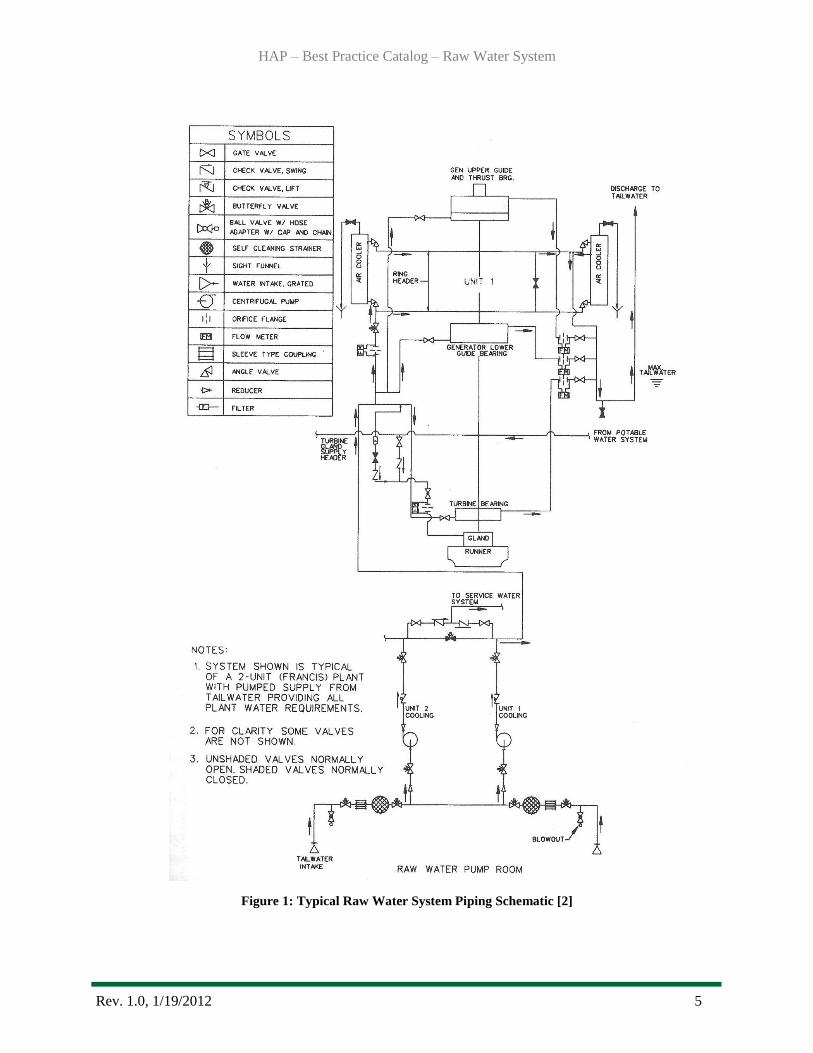
1.1.1 Raw Water System Components
The raw water system is critical to unit operation in its global plant cooling function. The
reliability related components of raw water systems include the supply intake, strainers,
pumps, valves, generator air coolers, piping and instrumentation/monitoring. The raw
water system is fed either from the units‟ forebay, penstock, or scroll case or pumped
from the tailrace/tailwater. Tailrace/tailwater is normally the source for lower head
plants. Forebays, penstocks or scroll cases is normally the source for higher head plants.
The water source is therefore defined as either gravity or pumped type cooling system. In
all plants, an intake for unit cooling, sealing and lubrication water is provided for each
unit with the supply lines between units manifolded or cross connected for flexibility.
Figure 1 is a typical schematic of the raw water system and it shows the comprehensive
nature as it services a wide variety of other hydropower systems.
HAP – Best Practice Catalog – Raw Water System
Rev. 1.0, 1/19/2012 5
Figure 1: Typical Raw Water System Piping Schematic [2]

HAP – Best Practice Catalog – Raw Water System
Rev. 1.0, 1/19/2012 6
Supply Intake: The function of the supply intake is to feed the raw water system with
river, dam or untreated water. Unit cooling, lubricating and sealing water pressure is
usually supplied at a maximum pressure of 40 pounds per square inch (around 28 m of
water) to prevent damage to the generator air coolers and other equipment.
Strainers: The function of the strainer is to remove suspended solid material (wood,
rocks, sand, biological matter, etc) from the raw water to minimize fouling of the
generator air coolers and oil cooler heat exchangers. The strainer must be back flushed
when the differential pressure across the strainer reached a set point value to ensure the
raw water flow rate is not reduced due to blockage of the strainer.
Pumps: The function of the raw (cooling) water pumps, if so equipped, is to develop
sufficient flow and head to meet the requirements of the equipment it services. This
ensures the water in the piping, strainer, valves and air coolers will be supplied at
required flow and pressure. The design must allow for the operation of the raw water
component in a fouled condition. Higher head plants/units normally do not require
pumps.
Valves: The function of the valves within a raw water cooling system is to route,
regulate, or isolate as required, the flow of water. There are multiple types of valves and
designs based on their specific application. Chief among these are gate, butterfly, globe,
control, ball and check valves. In the high head plants pressure must be reduced by
pressure regulating valves for most raw water services. A relief valve on the low-pressure
side of each pressure regulating valve protects against piping or equipment damage which
might result from over pressurization resulting from faulty operation of the valve. A
proportioning valve is used to control the flow of cooling water to the generator air
coolers.
Generator air coolers: Generator air coolers, which are considered as part of the
Generator (see Best Practice Catalog - Generator), are heat exchangers located in the
generator air housings which employ raw water to cool circulating air which in turn cools
the generator. Cooling water is delivered to a header serving all air coolers. This header is
sized by the generator manufacturer to distribute approximately equal flow to each
cooler. From the air cooler water returns via another header to a discharge chamber
designed to keep the air coolers full of water at all times. The cooling water headers are
normally circular.
Piping: The function of the piping is to connect supply water from the forebay/
penstock/scroll case/tailwater to rest of the system at the design water flow rate and
pressure to achieve optimum cooling of system components.
Instrumentation/Monitoring: The function of the instrumentation is to measure, monitor
and regulate the process variables of the raw water, such as flow, temperature and
HAP – Best Practice Catalog – Raw Water System
Rev. 1.0, 1/19/2012 7
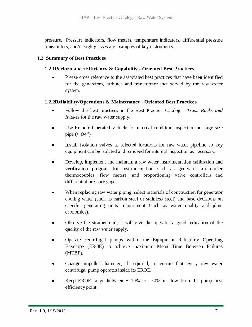
pressure. Pressure indicators, flow meters, temperature indicators, differential pressure
transmitters, and/or sightglasses are examples of key instruments.
1.2 Summary of Best Practices
1.2.1Performance/Efficiency & Capability - Oriented Best Practices
Please cross reference to the associated best practices that have been identified
for the generators, turbines and transformer that served by the raw water
system.
1.2.2Reliability/Operations & Maintenance - Oriented Best Practices
Follow the best practices in the Best Practice Catalog - Trash Racks and
Intakes for the raw water supply.
Use Remote Operated Vehicle for internal condition inspection on large size
pipe (> Ø4”).
Install isolation valves at selected locations for raw water pipeline so key
equipment can be isolated and removed for internal inspection as necessary.
Develop, implement and maintain a raw water instrumentation calibration and
verification program for instrumentation such as generator air cooler
thermocouples, flow meters, and proportioning valve controllers and
differential pressure gages.
When replacing raw water piping, select materials of construction for generator
cooling water (such as carbon steel or stainless steel) and base decisions on
specific generating units requirement (such as water quality and plant
economics).
Observe the strainer unit; it will give the operator a good indication of the
quality of the raw water supply.
Operate centrifugal pumps within the Equipment Reliability Operating
Envelope (EROE) to achieve maximum Mean Time Between Failures
(MTBF).
Change impeller diameter, if required, to ensure that every raw water
centrifugal pump operates inside its EROE.
Keep EROE range between + 10% to –50% in flow from the pump best
efficiency point.

HAP – Best Practice Catalog – Raw Water System
Rev. 1.0, 1/19/2012 8
Keep raw water centrifugal pump curves in the control room. Operators should
be trained and instructed on their use for optimizing centrifugal pump safety
and MTBF.
Monitor the raw water pump flow range by inputting the pump shop test curve
and collecting transmitter signals (inlet pressure, discharge pressure and flow)
into spreadsheets to calculate the pump head and flow.
Adjust head of the raw water supply as required to facilitate the pumps
operation within the EROE.
Label raw water system piping with colored tape to help personnel to
understand system operation and how to take corrective action quickly to
prevent unit performance or availability issues.
Installation of raw water strainers with automatic backwash capabilities will
reduce labor intensity associated with maintaining acceptable strainer pressure
differentials especially at locations that are not continuously staffed.
Place a higher priority on removal of generator air cooler bio-fouling than the
bio-fouling of the raw water pipe unless it has reduced the flow to a level
below the design flow.
1.3 Best Practice Cross-references
I&C - Automation Best Practice
Mechanical – Francis Turbine Best Practice
Mechanical – Kaplan Turbine Best Practice
Mechanical – Pelton Turbine Best Practice
Mechanical – Generator Best Practice
Civil – Trash racks and Intakes Best Practice
HAP – Best Practice Catalog – Raw Water System
Rev. 1.0, 1/19/2012 9
2.0 Technology Design Summary
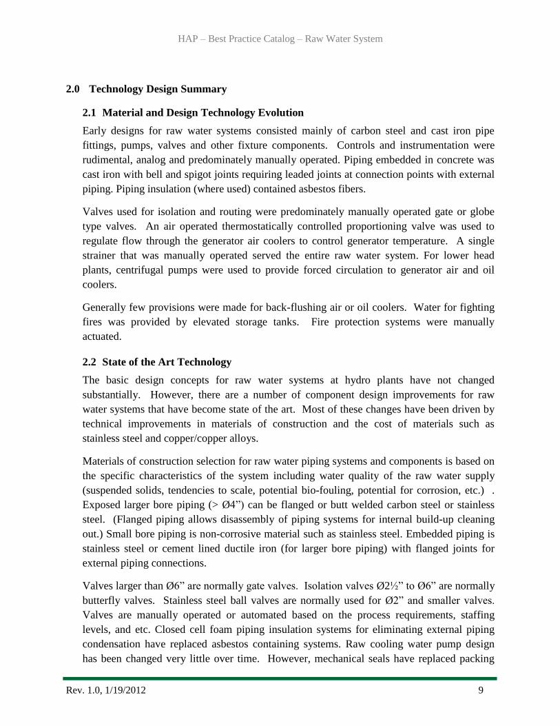
2.1 Material and Design Technology Evolution
Early designs for raw water systems consisted mainly of carbon steel and cast iron pipe
fittings, pumps, valves and other fixture components. Controls and instrumentation were
rudimental, analog and predominately manually operated. Piping embedded in concrete was
cast iron with bell and spigot joints requiring leaded joints at connection points with external
piping. Piping insulation (where used) contained asbestos fibers.
Valves used for isolation and routing were predominately manually operated gate or globe
type valves. An air operated thermostatically controlled proportioning valve was used to
regulate flow through the generator air coolers to control generator temperature. A single
strainer that was manually operated served the entire raw water system. For lower head
plants, centrifugal pumps were used to provide forced circulation to generator air and oil
coolers.
Generally few provisions were made for back-flushing air or oil coolers. Water for fighting
fires was provided by elevated storage tanks. Fire protection systems were manually
actuated.
2.2 State of the Art Technology
The basic design concepts for raw water systems at hydro plants have not changed
substantially. However, there are a number of component design improvements for raw
water systems that have become state of the art. Most of these changes have been driven by
technical improvements in materials of construction and the cost of materials such as
stainless steel and copper/copper alloys.
Materials of construction selection for raw water piping systems and components is based on
the specific characteristics of the system including water quality of the raw water supply
(suspended solids, tendencies to scale, potential bio-fouling, potential for corrosion, etc.) .
Exposed larger bore piping (> Ø4”) can be flanged or butt welded carbon steel or stainless
steel. (Flanged piping allows disassembly of piping systems for internal build-up cleaning
out.) Small bore piping is non-corrosive material such as stainless steel. Embedded piping is
stainless steel or cement lined ductile iron (for larger bore piping) with flanged joints for
external piping connections.
Valves larger than Ø6” are normally gate valves. Isolation valves Ø2½” to Ø6” are normally
butterfly valves. Stainless steel ball valves are normally used for Ø2” and smaller valves.
Valves are manually operated or automated based on the process requirements, staffing
levels, and etc. Closed cell foam piping insulation systems for eliminating external piping
condensation have replaced asbestos containing systems. Raw cooling water pump design
has been changed very little over time. However, mechanical seals have replaced packing

HAP – Best Practice Catalog – Raw Water System
Rev. 1.0, 1/19/2012 10
glands. Advances in pump materials of construction, impeller design and manufacturing, and
more efficient motor design provide improvements in pump reliability and operating costs.
Modern raw water pump set-up Figure 2.
Figure 2: Typical Dual Raw Water Pump Set-Up
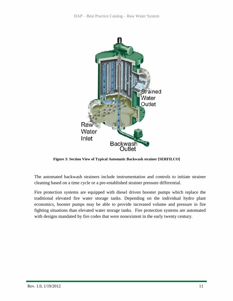
Current raw water system designs include stainless steel duplex automatic backwash strainers
(see Figure 3). Subsystems such as turbine seal water and fire protection can be equipped
with finer mesh automatic backwash strainers for additional reliability of these systems.
These automated features are used as labor saving methods, especially suitable for facilities
that are not continually staffed.
HAP – Best Practice Catalog – Raw Water System
Rev. 1.0, 1/19/2012 11
Figure 3: Section View of Typical Automatic Backwash strainer [SERFILCO]
The automated backwash strainers include instrumentation and controls to initiate strainer
cleaning based on a time cycle or a pre-established strainer pressure differential.
Fire protection systems are equipped with diesel driven booster pumps which replace the
traditional elevated fire water storage tanks. Depending on the individual hydro plant
economics, booster pumps may be able to provide increased volume and pressure in fire
fighting situations than elevated water storage tanks. Fire protection systems are automated
with designs mandated by fire codes that were nonexistent in the early twenty century.
HAP – Best Practice Catalog – Raw Water System
Rev. 1.0, 1/19/2012 12
3.0 Operation & Maintenance Practices
3.1 Condition Assessment
The supply intake for the raw water system can be assessed at two locations depending on the
plant layout. If the penstock is tapped for the raw water supply then the trash rack condition
assessment becomes critical for the same reasons that the turbines must be supplied debris
free water. If the raw water is drawn from the trail water then the intake structures of raw
water supply become important. In both cases see the condition assessment best practices in
the Best Practice Catalog Trash Racks and Intakes. Unusual biological fouling by plants,
fauna, fish and flood debris is a real issue, varies widely, and must be evaluated for specific
sites.
Raw water pipe is difficult to evaluate for wall thickness or pinhole leaks. “D” meter
readings of wall thickness are considered unreliable due to fouling on the inside of the pipe
that may be ½ to ¾ of an inch on Ø6-8” pipe. Pinhole leaks may ultimately develop along the
length of the piping system so replacement is typically justified.
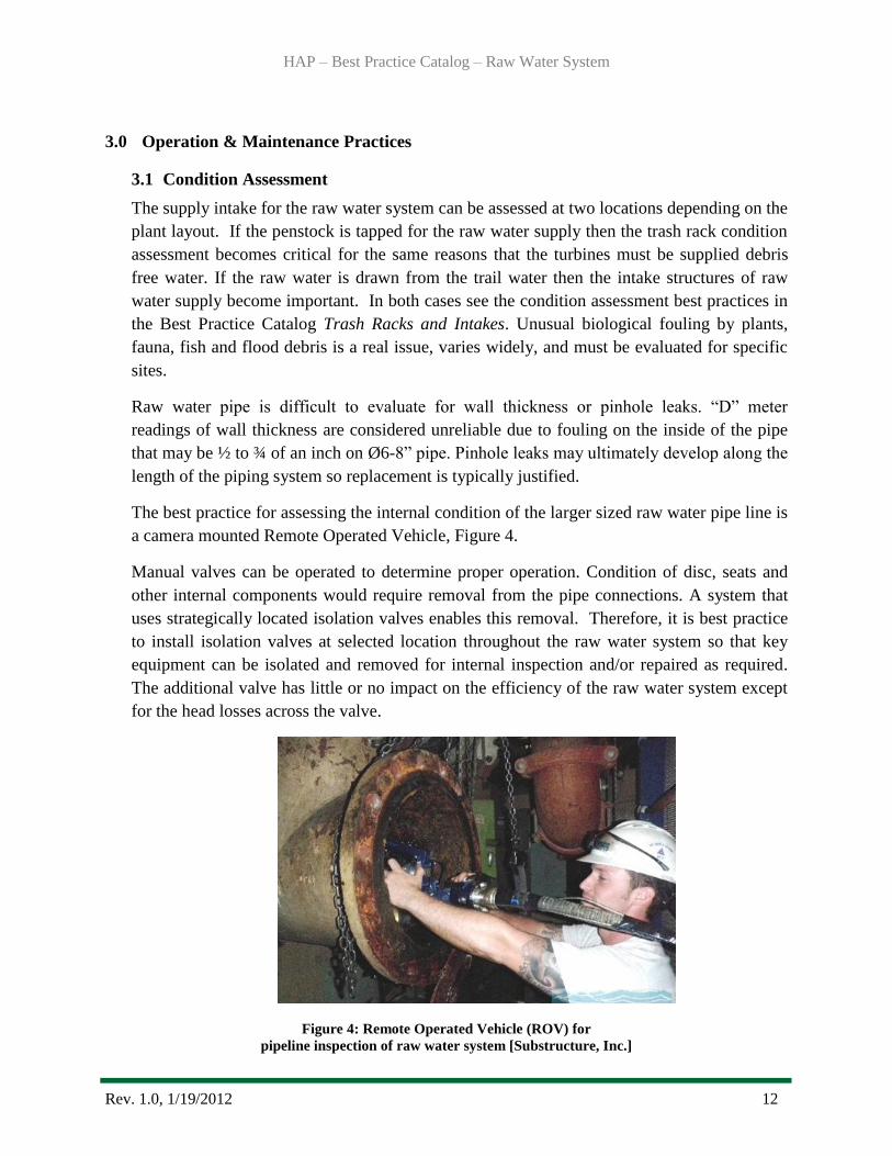
The best practice for assessing the internal condition of the larger sized raw water pipe line is
a camera mounted Remote Operated Vehicle, Figure 4.
Manual valves can be operated to determine proper operation. Condition of disc, seats and
other internal components would require removal from the pipe connections. A system that
uses strategically located isolation valves enables this removal. Therefore, it is best practice
to install isolation valves at selected location throughout the raw water system so that key
equipment can be isolated and removed for internal inspection and/or repaired as required.
The additional valve has little or no impact on the efficiency of the raw water system except
for the head losses across the valve.
Figure 4: Remote Operated Vehicle (ROV) for
pipeline inspection of raw water system [Substructure, Inc.]
HAP – Best Practice Catalog – Raw Water System
Rev. 1.0, 1/19/2012 13
The raw water system requires instrumentation to monitor and provide information to help
control system equipment such as pumps and strainers. Instruments should be checked and
re-checked for accuracy, especially air cooler thermocouples, stator core Resistance
Temperature Detectors (RTDs), flow meters, shunt voltage readings, proportioning valves
controller, and isolation valve operators. Operability of the proportioning valves can be
readily determined as to whether the valves are adjusting water flow for variations in air
temperature. The correct function must be determined by the supplier‟s Original Equipment
Manufacturers (OEMs) engineering documents. Some temperatures can be checked with
hand held thermocouples, heat guns, and thermal imaging equipment, depending on
accessibility. Differential pressure gauges should be checked to ensure operability and
accuracy. A common problem with differential pressure gauges is fouled or blocked pressure
tubing.
Materials for Generator Cooling System piping may be cast iron, carbon steel, or stainless
steel. The hydraulic performance for each type is detailed in numerous piping industry
handbooks; Cameron Hydraulic Data is highly regarded [5]. As a best practice, the most
common material would be ASME B36.10 Welded and Seamless Wrought Steel Pipe [6],
constructed to ASME B31.3 Process Piping [7] standard.
The strainer unit will give the operator a good indication of the quality of the raw water
supply. The best practice for evaluating the raw water strainer condition is based on two
indicators, pressure differential trend data across the unit and the strainers performance after
a back flush to operate at rated pressure drop or lower.
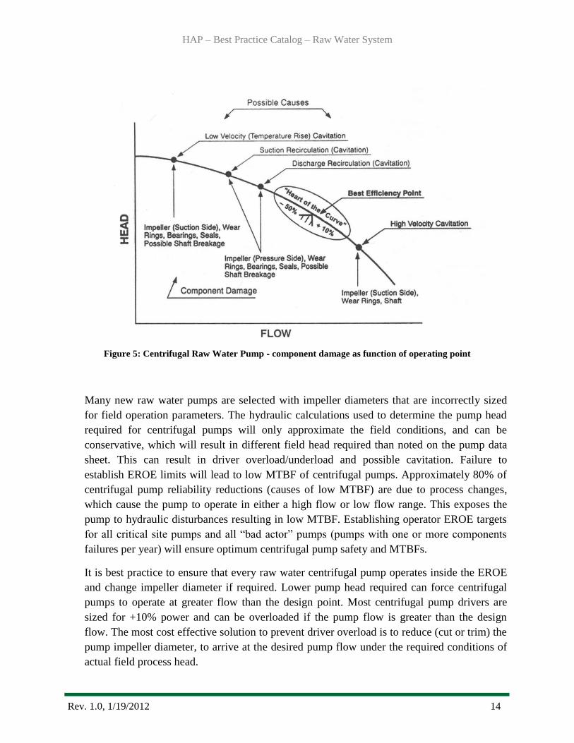
3.2 Operations
When it comes to the operation of a raw water system, how the pumps are efficiently used is
critical to the cooling process. It is best practice to operate centrifugal pumps within the
Equipment Reliability Operating Envelope (EROE) to achieve maximum Mean Time
Between Failures (MTBF). The EROE, also called the heart of the curve (Figure 5), assures
maximum centrifugal pump MTBF by avoiding all operating areas of hydraulic disturbances.
An established best practice for the EROE range should be + 10% to – 50% in flow from the
pump best efficiency point.
HAP – Best Practice Catalog – Raw Water System
Rev. 1.0, 1/19/2012 14
Figure 5: Centrifugal Raw Water Pump - component damage as function of operating point
Many new raw water pumps are selected with impeller diameters that are incorrectly sized
for field operation parameters. The hydraulic calculations used to determine the pump head
required for centrifugal pumps will only approximate the field conditions, and can be
conservative, which will result in different field head required than noted on the pump data
sheet. This can result in driver overload/underload and possible cavitation. Failure to
establish EROE limits will lead to low MTBF of centrifugal pumps. Approximately 80% of
centrifugal pump reliability reductions (causes of low MTBF) are due to process changes,
which cause the pump to operate in either a high flow or low flow range. This exposes the
pump to hydraulic disturbances resulting in low MTBF. Establishing operator EROE targets
for all critical site pumps and all “bad actor” pumps (pumps with one or more components
failures per year) will ensure optimum centrifugal pump safety and MTBFs.
It is best practice to ensure that every raw water centrifugal pump operates inside the EROE
and change impeller diameter if required. Lower pump head required can force centrifugal
pumps to operate at greater flow than the design point. Most centrifugal pump drivers are
sized for +10% power and can be overloaded if the pump flow is greater than the design
flow. The most cost effective solution to prevent driver overload is to reduce (cut or trim) the
pump impeller diameter, to arrive at the desired pump flow under the required conditions of
actual field process head.
HAP – Best Practice Catalog – Raw Water System
Rev. 1.0, 1/19/2012 15
The safety and reliability of all centrifugal pumps is optimized if pumps are operated within
the equipment reliability operating envelope. It is best practice to have raw water centrifugal
pump curve available in the control room and operators need to be trained for using pump
test curves to optimize centrifugal pump safety and MTBF. Centrifugal pumps produce flow
inversely proportional to the required process head. This flow range is obtained by having
operations aware of the centrifugal pump characteristic, providing process targets and having
the pump test curves available for each pump for operator use and understanding.
Unnecessary centrifugal pump maintenance and pump failures result from operators not
checking the pump test curves, or not confirming that the pump operates within its EROE
and not understanding their use.
It is an instrumentation best practice for monitoring, in the control room, the raw water pump
flow range by inputting the pump shop test curve and collecting transmitter signals (inlet
pressure, discharge pressure and flow) into spreadsheets to calculate the pump head and flow.
Even if flow meters are not installed for each pump, EROE targets should be established by
other methods (control valve position, motor amps, pump inlet and discharge piping
differential temperature). Critical centrifugal and „bad actor pumps‟ require constant
surveillance by operators to ensure optimum safety and reliability.
It is a best practice to adjust head as required. Head required in raw water pumping system
can be changed by adjusting the discharge system resistance using pressure control, flow
control or level control. Each of these methods results in closing a throttle valve in the
discharge piping which increases the head (energy) required and reduces the flow rate. This
action requires more energy (head) to overcome the increased system resistance.
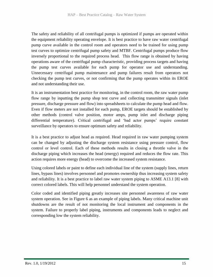
Using colored labels or paint to define each individual line of the system (supply lines, return
lines, bypass lines) involves personnel and promotes ownership thus increasing system safety
and reliability. It is a best practice to label raw water system piping to ASME A13.1 [8] with
correct colored labels. This will help personnel understand the system operation.
Color coded and identified piping greatly increases site personnel awareness of raw water
system operation. See in Figure 6 as an example of piping labels. Many critical machine unit
shutdowns are the result of not monitoring the local instrument and components in the
system. Failure to properly label piping, instruments and components leads to neglect and
corresponding low the system reliability.
HAP – Best Practice Catalog – Raw Water System
Rev. 1.0, 1/19/2012 16
Figure 6: Piping Labeling from ASME 13.1 [8]
Proportioning valves control the raw water flow to the generator air coolers for maintaining
proper generator air temperature. The benefit of the proportioning valve is in a situation
where the generator is operating in load following mode with significant changes in MVA
output. The valve controller would be set to the desired air temperature. Generator air cooler
flow balancing is a common operational procedure and should be readily accomplished by
plant staff. Air cooler discharge temperature should be checked from each cooler to ensure
uniform cooling.
3.3 Maintenance
The raw cooling water to the strainer performance condition is typically judged by the
differential pressure across the strainer (Figure 7).

HAP – Best Practice Catalog – Raw Water System
Rev. 1.0, 1/19/2012 17
Figure 7: Typical differential pressure gauge with feedback switch [EATON]
However, high differential is due to fouling of the strainer which can be corrected by
installing a back flush feature. Most strainers are designed with a 1/16” to 1/32” screen
size to allow small particles to pass for scouring action in the pipes and heat exchanger
tubes. If the strainer elements are failed, the strainer is essentially a piece of pipe which
does not remove the larger and detrimental debris. Unusual biological fouling, including
small fish (shad) and flood debris, can present a problem, but should normally be
corrected with a well designed back flush system. The strainer should require minimal
maintenance except to replace the internal elements that may degrade with time.
The generator raw water pipe and generator air cooler tubes foul in any system. The
cleaning of the raw water pipe is probably of minimum value unless the fouling actually
reduces raw water flow to below design value. The generator air cooler tubes are much
more of an issue and require periodic cleaning to maintain acceptable performance.
With modern air cooler design, the efficiency of the air cooler will be very similar to a
counter flow heat exchanger. The old generator air coolers were similar to a cross flow
heat exchanger with a much reduced thermal efficiency. The best measure is the
difference between the raw water cold inlet temperature, and the cold air discharge
temperature. The raw water temperature is the theoretical temperature as to how much
the cold air temperature can be lowered.
HAP – Best Practice Catalog – Raw Water System
Rev. 1.0, 1/19/2012 18
Typical efficient coolers will have a cold air discharge temperature of approximately 5°C
above the raw water inlet temperature. In the case of badly fouled tubes and degraded
fins, the air temperature approach to the raw water temperature may be 15°C to 20°C. In
the case of 30°C water inlet temperature, the maximum design air temperature of 40°C
would be exceeded and the cold air temperature would be 45°C to 50°C.
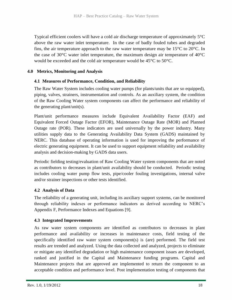
4.0 Metrics, Monitoring and Analysis
4.1 Measures of Performance, Condition, and Reliability
The Raw Water System includes cooling water pumps (for plants/units that are so equipped),
piping, valves, strainers, instrumentation and controls. As an auxiliary system, the condition
of the Raw Cooling Water system components can affect the performance and reliability of
the generating plant/unit(s).
Plant/unit performance measures include Equivalent Availability Factor (EAF) and
Equivalent Forced Outage Factor (EFOR), Maintenance Outage Rate (MOR) and Planned
Outage rate (POR). These indicators are used universally by the power industry. Many
utilities supply data to the Generating Availability Data System (GADS) maintained by
NERC. This database of operating information is used for improving the performance of
electric generating equipment. It can be used to support equipment reliability and availability
analysis and decision-making by GADS data users.
Periodic fielding testing/evaluation of Raw Cooling Water system components that are noted
as contributors to decreases in plant/unit availability should be conducted. Periodic testing
includes cooling water pump flow tests, pipe/cooler fouling investigations, internal valve
and/or strainer inspections or other tests identified.
4.2 Analysis of Data
The reliability of a generating unit, including its auxiliary support systems, can be monitored
through reliability indexes or performance indicators as derived according to NERC‟s
Appendix F, Performance Indexes and Equations [9].
4.3 Integrated Improvements
As raw water system components are identified as contributors to decreases in plant
performance and availability or increases in maintenance costs, field testing of the
specifically identified raw water system component(s) is (are) performed. The field test
results are trended and analyzed. Using the data collected and analyzed, projects to eliminate
or mitigate any identified degradation or high maintenance component issues are developed,
ranked and justified in the Capital and Maintenance funding programs. Capital and
Maintenance projects that are approved are implemented to return the component to an
acceptable condition and performance level. Post implementation testing of components that

HAP – Best Practice Catalog – Raw Water System
Rev. 1.0, 1/19/2012 19
are replaced/modified or otherwise repaired is conducted to verify that issues that resulted in
decreased unit/plant performance and/or reliability have been addressed.
5.0 Information Sources:
Baseline Knowledge:
1. EPRI, TR-112350-V4 Hydro Life Extension Modernization Guides: Volume 4-5 Auxiliary
Mechanical and Electrical Systems– Palo Alto, CA – 2001
2. ASME, The Guide to Hydropower Mechanical Design, HCI Publications Inc., 1996
3. TVA, Technical report No.24 Mechanical Design of Hydro Plants, US Government
Printing Office – Washington - 1960
State of the Art:
4. Forsthoffer, W., E., Best Practice Handbook for Rotating Machinery – 2011
5. Heald, C., C., Cameron Hydraulic Data – Nineteenth Edition -2002
Standards:
6. ASME A36.10, Welded and Seamless Wrought Steel Pipe - 2004
7. ASME B31.3, Process Piping ASME Code for Pressure Piping – 2008
8. ASME A13.1, Scheme for Identification of Piping Systems -2007
9. NERC, Appendix F, Performance Indexes and Equations - January, 2011
It should be noted by the user that this document is intended only as a guide. Statements are
of a general nature and therefore do not take into account special situations that can differ
significantly from those discussed in this document.
HAP – Best Practice Catalog – Raw Water System
Rev. 1.0, 1/19/2012 20
For overall questions
please contact:
Brennan T. Smith, Ph.D., P.E.
Water Power Program Manager
Oak Ridge National Laboratory
865-241-5160
or
Qin Fen (Katherine) Zhang, Ph. D., P.E.
Hydropower Engineer
Oak Ridge National Laboratory
865-576-2921