Bertom and McCartney Lakes EMP - Operation and … and maintenance manual bertom and mccartney lakes...
49
Transcript of Bertom and McCartney Lakes EMP - Operation and … and maintenance manual bertom and mccartney lakes...


-m ANDMAINTENANCEMANUAL BERTOM AND MCCARTNEY LAKES
REHABILlTATI4)N AND ENHANCEMENT
UPPER MISSISSIPPI RIVER ENVIRONMENTAL MANAGEMENT PROGRAM
POOL 11, RIVER MILES 599 THROUGH 603 GRANT COUNTY, WISCONSIN
TABLE OF CONTEm
1. INTRODUCTION a. Purpose and Scope . . . . . . . . . . . . . . . . . . . . . . . . . . . . . . ..*...a..... . . . . . . . . . . . . . . . . . . . . . . . . . . . . . . . . . . . . . . . . . . . . . 1 b. Use of Manual . . . . . . . . . . . . . . . . . . . . . . . . . . . . . . . . . . . . . . . . . . . . . . . . . . . . . . . . . . . . . . . . . . . . . . . . . . . . . . . . . . . . . . . . . . . . . . 1
2. HISTORICAL SUMMARY a. Authorization and Location .......................................................................... 2 b. Planning and Construction Activities ............................................................. 2 c. Actual Project Costs ..................................................................................... 5 d. Project References ...... . ................................................................................. 7
3. DESCRIPTION OF PROJECT FEATURES a. Project Data ................................................................................................. 8
b. Partial Closing Structure ............................................................................... 9 c. Fish and Mussel Rock Habit ....................................................................... 9 d. McCartney Lake Dredging ........................................................................... 9 e. Confined Dredged Material Placement Site ................................................... 9
4. INSPECTIONS a. General ....................................................................................................... to b .. Project Inspection by Site Manager ............................................................. 10 c. Joint Inspection by Siie Manager and Corps of Engineers ........................... 11
5. OPERATiON AND MAINTENANCE OF PROJECT FEATURES a. General ....................................................................................................... b. Partial Closing Structure ................................................................. ............ :: c. Fish and Mussel Rock Habitat ..................................................................... I2 d. McCartney Lake Dredging ......................................................................... 13 e. Confined Dredged Material Placement Site.. ............................................... 13
6. PERFORMANCE MONITORING AND ASSESSMENT
7. PROJECT REHABILITATION OR AI3ANDONMEN’I’
i

. .
OF CONTENTS (Continued)
. f Tables
No. Titie Page
2.1 2.2 2.3 2.4 3.1 5.1 6.1 6.2 6.3
Summary of Planning and Construction Activities ........................................ 3 Project Objectives ..: ..................................... .................................................... 5 Actual Project Costs ....................................................................................... 6 Project References .......................................................................................... 7 Project Data Summary .................................................................................... 8 Riprap Replacement Material ....................................................................... 12 Monitoring and Performance Evaluation Matrix ......................................... 15 Resource Monitoring and Data Collection Surnrnary .................................. 16 Performance Evaluation Plan ...................................................................... .23
,
A - Operation, Maintenance, and Rehabilitation Agreement B - Site Manager’s Project Inspection and Monitoring Results C - Distribution List
&!s
C-l c-2 c-7 C-8 c-9 c-10 C-11 c-12 c-13 MP-1 MP-2 I
Bertom Lake Site Plan McCartney Lake Site Plan Dredging Plan I Dredging Plan II Dredging Plan III Containment Facility Plan Dredging and Containment Facility Sections Rock Habitat Channel Site Plan Habitat Structures Plans and Details Bertom Lake Monitoring Plan McCartney Lake Monitoring Plan
ii

OPERATION AND MAINTENANCE MANUAL BERTOM AND MCCARTNEY LAKES
REHABILITATION AND ENHANCEMENT
UPPER MISSISSIPPI RIVER ENVIRONMENTAL MANAGEMENT PROGRAM
POOL 11, RIVER MILES 599 THROUGH 603 GRANT COUNTY, WISCONSIN
1. INTRODUCTION.
a. Pumose and Scoue .
(1) This manual has been prepared to serve as a guide for the operation and maintenance of Bertom and McCartney Lakes Rehabilitation and Enhancement project. Operation and maintenance instructions for the major features of the project are presented. These instructions are consistent with the general procedures presented in the Definite Project Report (DPR). This manual has been written for project and management personnel familiar with the project and does not contain detailed information which is common to site personnel or which is presented in other existing manuals or regulations.
(2) The intent of the operating instructions is to provide information which allows orderly and efficient use of the constructed features to meet project goals and objectives. The intent of the maintenance instructions is to present preventative maintenance information consisting of systematic inspections and subsequent corrective actions which should ensure long-term utilization of equipment and features. A timely preventative maintenance program reduces and virtually eliminates breakdown of essential equipment and prevents major damage to constructed features by early corrective action.
(3) This manual provides the general standards of maintenance and establishes an initial frequency of maintenance inspections which should ensure satisfactory project performance.
b. Useof
(1) This manual is divided into the following sections: Section 1: Introduction; Section 2: Historical Summary; Section 3: Description of Project Features; Section 4: Inspections; Section 5: Operation and Maintenance of Project Features; and Section 6: Performance Monitoring and Assessment.
(2) Sections 2 and 3 present historical summaries and descriptions of actual features constructed for this project. Section 4 presents project inspection procedures and Section 5 presents operation and maintenance instructions for each project feature. Section 6 provides a summary of monitoring activities conducted through construction and provides an overview of continued monitoring actions. Performance monitoring is considered necessary to properly evaluate effects of the constructed project features.
1

(3) The attached drawings have been included to provide general project “as-built” views, typical sections, and plans.
2. HISTORICAL SUMMARY.
. . . a. Authorlzatlon and I,Q~ .
(1) The authority for this project was provided by the 1985 Supplemental Appropriations Act (Public Law 99-88) and Section 1103 of the Water Resources Development Act of 1986 (Public Law 99-662). The project was funded and constructed under this authorization by the U.S. Army Corps of Engineers, Rock Island District, in cooperation with the U.S. Fish and Wildlife Service (USFWS) and the State of Wisconsin, Department of Natural Resources (WDNR).
(2) The Bertom and McCartney Lakes Backwater Complex is located on the east bank of Pool 11, approximately 3 river miles south of Cassville, Wisconsin. The project features lie entirely within an area of the Upper Mississippi River National Wildlife and Fish Refuge.
. . . . b. Planning Co-on ActwltleS .
(1) Table 2.1 provides a summary of planning and construction activities.
(2) Goals and objectives were formulated during the design phase. Table 2.2 summarizes project objectives.
(3) The project was designed by the U.S. Army Corps of Engineers, Rock Island District, in cooperation with the USFWS and the WDNR. Design considerations and investigations are presented in the Definite Project Report. The construction contract was supervised by the U.S. Army Corps of Engineers, Rock Island District.
(4) A construction contract, number DACW90-C-0020, was awarded to J. F. Brennan Company, La Crosse, Wisconsin, on 5 January 1990 in the amount of $1,866,277.50. This bid was 72% of the Government estimate.
(5) Constructipn Problem. One construction problem encountered was mounding of heavier materials at the dredge pipe inlet of the dredged material containment facility. This resulted in a reduced settling efficiency of the containment area. To remedy this problem, the contractor constructed spur dikes to increase the linear flow length of the dredged water and therefore avoided short circuiting.
Another construction problem encountered was an insufficient quantity of silt clay material available within the containment site to dress the containment dike slopes. To rectify this problem, the contractor used material from the outside toe of the containment dike to dress the slopes.
2

W
TABLE 2.1 SUMMARY OF PLANNING AND CONSTRUCTION ACTIVITIES
reject hase Purpose
Responsible Sieniticant Events Agency Item Date Remarks
.e-project Identify and define problems and establish need of project.
WDNR/USFWS Fact Sheet Submitted to Corps Approved by Corps
Sep 86 Jun 87
-_ __
esign Quantify project objectives, perform preliminary design, satisfy NEPA and permit requirements, develop performance evaluation plan, obtain project approval for construction.
CORPS Definite Project Report Draft Final Approved
NEPA Compliance SHPO Concurrence Public Review FONSI for EA
Jan 89 Jun 89 Nov 89
Feb 89 Apr 89 Jun 89
Permits Section 40 1 Section 404 Refuge Compatibility
Feb 89 Jun 89 Mar 89
onstruction Finalize plans and specifications, obtain operation and maintenance agreement, advertise and award construction contract, construct project.
CORPS Plans and Specifications Final Approved
Real Estate Lands Available
from USFWS Contributed Funds Received O&M Agreement
Ott 89 Nov 89
Jun 89 N/A Nov 89
__ __
__ __
Reference Appendix A

P
TABLE 2.1 (Continued) SUMMARY OF PLANNING AND CONSTRUCTION ACTIVITIES
Project Phase
Zonstruction continued)
Purpose Responsible
Agency Significant Events
Item Date Remarks
Dredging Contract Advertised Nov 89 __ Awarded Jan 90 __ Substantially Complete Ott 91 __
‘ost- Construction
Operate and maintain project. USFWS __ __ Reference Sections 4 and 5.
Post flood inspection
Perform evaluation monitoring.
CORPS
CORPS
Great Flood of 93 Damage Assessment
Performance Evaluation
Feb 94
May 95
__
Reference Section 6.
I/ A FONSI was completed by both the Corps and the USFWS.

TABLE 2.2 PROJECT OBJECTIVES
Goal
Enhance Aquatic Habitat
Objective
Restore deep (6 feet) aquatic habitat.
Project Feature
Dredging
Restore lentic-lotic habitat access cross-sectional area.
Side channel excavation
Increase rock substrate aquatic habitat.
Fish and mussel rock habitat
Establish mussel bed.
Reduce movement of bedload sediment into Bet-tom Lake.
Fish and mussel rock habitat
Partial closing structure
Improve dissolved oxygen concentration during critical seasonal stress periods
Dredging
Enhance Migratory Waterfowl Habitat
Establish aquatic vegetation bed. In-water confined dredged material placement site
c. Actual Project Costq. The actual cost of the project is presented in Table 2.3 on the following page.
5

TABLE 2.3 ACTUAL PROJECT COSTS
06. FISH AND WILDLIFE FACILITIES
Line Item Description QW Number _________ ______________________________~~~~~~~~~~~~ -.
Temporary Field Office
River Miles 599-603, Upper Mississippi
River System, Environmental Management
Program, Grant County, WI
Hydraulic Dredging, Mobilization and
Demobilization
Hydraulic Dredging, Removal and
Disposal of Stumpa, First 200 Bach
Hydraulic Dredging, Removal and
Disposal of Stumps, Over 200 Each
Hydraulic Dredging, Dredging
Dredged Material Containment Facility
Clearing and Grubbing
Channel Excavation
Submerged Habitat Structures, Heavy
Timber
Submerged Habitat Structures, Concrete
Rock Substrate/Bank Protection
Stone/Rock Fill/Bedding, Gradation A
Rock Substrate/Bank Protection
Stone/Rock Fill/Bedding, Gradation B
Rock Substrate/Bank Protection
Stone/Rock Fill/Bedding,
Gradation C
Rock Substrate/Bank Protection
Rock Substrate/Bank Protection
Stone/Rock Fill/Bedding, Gradation El
Rock Substrate/Bank Protection Stone/Rock Fill/Bedding, Gradation E2
Rock Substrate/Bank Protection
Rock Substrate/Bank Protection
Stone/Rock Fill/Bedding, Gradation G
Seeding, Type A
Seeding, Type B
1
1 LS $ 175.000.00
200 EA $ 24,OOO.OO
100 EA
0005
0006
0007
0008
0009
3961Oti
1
1
42OOd
4
CY
LS
LS
CY
EA
S 120.00
S 90.00
$ 1.30
$ 565,OOO.OO
56,OOO.OO
8.10
5,ooo.oo
$514.930.00
$565,000.00
$ 56.000.00
$ 34.020.00
$ 20.000.00
0010 24 ;:@j2i
EA
TN
425.00 $ 10,200.00
22.00 $ 95,700.oo
0012 6900 TN 22.50 $155.250.00
0013 1375 TN 23.00 $ 31,625.OO
0014 650 TN
625 TN
21.00 $ 13,650.OO
28.30 $ 17.687.50
0016 825 TN
0017 1950
600 _%~~--
TN
TN
0019
0020
1
1 LS
LS
S
$
$
$ s
S
s
S $
s
S s
$
$
21.00 $ 17,325.OO
18.20 $ 35.490.00
19.00 $ 11.400.00
10.000.00
50,000.00
$ 10,000.00
$ 50,000.00
06. TOTAL, FISH AND WILDLIFE FACILITIES Total $1,866,277.50
30.
31.
PLANNING, ENGINEERING, AND DESIGN $242,000.00
CONSTRUCTION MANAGEMENT $136.000.00
$2.244.277.54
ml cost Extended
TOTAL PROJ-
L
6

d. Project References. Table 2.4 provides a summary of related project references.
TABLE 2.4 PROJECT REFERENCES
Title
Definite Project Report, Bertom & McCartney Lakes Rehabilitation & Enhancement, U.S. Army Corps of Engineers, Rock Island District
Construction As-Builts
Date
June 1989
May 1993
Purpose
Provided planning, engineering, and sufficient construction details of the selected plan for project approval purposes.
Provides as-built construction drawings.
Contractor Submittals/ Manufacturer’s Data/ Shop Drawings
varies Provides construction product data to aid in project maintenance.

3. DESCRIPTION OF PROJECT FEATURES.
a. Proiect Data. Table 3.1 presents a summary of project data.
1,500 50
2 4
2:l
Q 9,
Approximate Length 8,200 Feet Bottom Width 60 or 130 Feet Bottom Elevation 594 or 590 MSL Volume of Excavation 400,000 CY
TABLE 3.1 PROJECT DATA SUMMARY
Item Quantity U/M
“artial Closing Structure
Main Structure Rock Fill Length Top Width Top Elevation Side Slopes
Rock Protection Wings Rock Fill Riprap Bedding Top Width Top Elevation Side Slopes
3,000 (1,875) 100
5 599 1:5
1,500 1,500
200 5
605 2:l
I:1
Tons (CY) Feet Feet MSL H:V
Tons Tons Tons Feet MSL H:V
From elevation 605-599 H:V
From elevation 599 to channel bottom
Tish and Mussel Rock Habitat
Length Minimum Bottom Width Average Depth of Rock Substrate Minimum Water Depth Side Slopes Rock Substrate
YlcCartney Lake Dredging
Feet Feet Feet Feet H:V Tons
dredged Material Placement Site
Area Average Material Depth Minimum Capacity Containment Levee
Volume of Levee Top Elevation Top Width Minimum Side Slopes
22 Acres 8 Feet
450,000 CY
160,000 CY 610 MSL
10 Feet 3.5:1 H:V
8

. -
b. Partial Closiw Structure.
(1) A submerged rock partial closing structure was placed across the mouth of the slough entrance immediately upstream from Coalpit Slough. The top elevation of the structure is 599 MSL, which provides 4 feet of water above the top of the structure at flatpool conditions. This water depth above the top of the structure allows sufficient flow over the structure such that its construction will not significantly impact the overall flow requirements of the backwater complex.
(2) The closing structure has 1: 1 side slopes with a 5-foot bench on the riverside slope. The closing structure is tied into the banks with riprap protection wings extending along the riverbank.
c. Fish and Mussel Rock Habitat. There are three components to the fish and mussel rock habitat: rock substrate; concrete pipe submerged habitat; and submerged timber structures.
(I) Rock Substrate. Graded rock was placed to provide habitat diversity for aquatic invertebrate, including mussels. The fishery benefits also will be realized with provision of this stable rock substrate in flowing water. The length of the rock habitat channel is approximately 1,500 feet and has been divided into discrete sections. The existing channel was excavated by dragline prior to rock placement.
(2) Submerged Concrete P&X. Select sections of concrete pipe also were placed in this reach to enhance fishery habitat. Twenty-five pipe sections varying in diameter from 12 to 36 inches were placed.
(3) Submeced Timber Structures. These structures consist of submerged planking which allows fishery streambank resting, feeding, and escape. These structures have been anchored into the streambed with rock backfill placed behind and on top of the structure. There are four individual structures which provide underwater openings of approximately 20 feet in length by 3 feet in height,
d. &l . -Lake . McCartney Lake was dredged to provide
additional side channel and slough aquatic habitat. The dredging provides lentic-lotic access to the oxygen deficient spring-fed bank line areas. The dredging also provides increased side channel flow into slough areas. The bottom width of the dredging varied by reach from either 60 or 130 feet with bottom elevations of either 594 or 590.
e. Confined DredPed Material Placement Site.
(1) A confined dredged material placement site was constructed to contain the dredged material from McCartney Lake. The construction consisted of the-placement of a sand ring levee using hydraulic dredging methods. To construct the sand ring, the contractor cleared clayey overburden from an area in the center of the containment facility
9

using mechanical dredging methods. The cleared overburden material was used to construct temporary containment berms. The contractor then mobilized a small hydraulic dredge into the contained cleared area and built the final sand containment levee. The contractor staged containment levee work to allow subsequent overburden clearing to take place within the contained areas, thereby allowing use of the hydraulic dredge for all subsequent overburden removal and sand borrow operations. After the ring levee was constructed, material from McCartney Lake dredging was placed in this structure.
(2) The approximate size of this area is 22 acres with a perimeter shoreline of approximately 4,500 feet. The riverside slopes of the structure were completed with the placement of a sediment topping to facilitate seeding.
4. INSPECTIONS.
a. General.
(1) An active maintenance program is based on inspections and subsequent servicing, adjustment, or repair. The objective of inspections is to obtain a balance between inspection costs and the cost of repairs and replacements that could be avoided by timely and thorough inspections.
(2) There are two types of inspections for the project: (1) Project Inspection by the Upper Mississippi River National Wildlife and Fish Refuge Manager and (2) Joint Inspection with the Wildlife Refuge Manager and personnel from the U.S. Army Corps of Engineers, Rock Island District.
b. Proiect Inwection bv Site Manwer.
(1) The Project Inspection should be performed by the Upper Mississippi River National Wildlife and Fish Refuge Manager or appropriate representative for the purpose of noting routine deficiencies and initiating corrective actions. This inspection should be performed at periods not exceeding 12 months and should follow inspection guidance presented in subsequent sections of this manual. It is suggested that the inspection be conducted every May, which is representative of after spring flood conditions. Other Project Inspections should occur as necessary afIer other high water events or as scheduled by the Site Manager.
(2) A checklist report covering inspection, operation, and maintenance of the habitat project shall be submitted each year to the District Engineer. A sample copy of the checklist can be found in Appendix B. Besides completion of the inspection checklist, each individual report should briefly summarize the condition of the entire system, including any maintenance work done during the past l-year period. The USFWS may send the Bertom and McCartney report in conjunction with reports on other habitat projects for which it has responsibility. If so desired, these reports can be sent to the Corps with the
10

annual Cooperative Agreement Report which is done every April by the USFWS. Reports should be furnished to the U.S. Army Corps of Engineers, Rock Island District, ATTN: CENCR-OD-S, Clock Tower Building, P.O. Box 2004, Rock Island, Illinois 61204-2004.
c. Joint Inmection by Site Manaper and Corps of Erwineers.
(1) Routine. A Joint Inspection by the Site Manager and the Corps of Engineers will be scheduled by the Corps in accordance with ER 1130-2-339. The purpose of this inspection is to assure that adequate maintenance is being performed as presented in the DPR and this manual. The District Engineer or Authorized Representatives should have access to all portions of the constructed project upon coordination with the Site Manager for this purpose. Copies of this inspection will be furnished to the Site Manager stating project maintenance conditions. Corrective actions from these inspections should be accomplished by the Site Manager as provided by USFWS Operation, Maintenance, and Rehabilitation Agreement, reference Appendix A.
(2) Catastrophic. A Joint Inspection by the Site Manager and the Corps of Engineers should be formally requested by the Site Manager immediately following a specific storm or flood event which causes damage exceeding the annual operation and maintenance as specified in this manual and the DPR. The Project Inspections by the Site Manager and Joint Inspection results will be the basis for determining maintenance responsibility and potential rehabilitation by the Corps of Engineers.
5. OPERATION AND MAINTENANCE OF PROJECT FEATURES.
a. General.
(1) This section presents operation and maintenance instructions for the major project features which were designed and constructed to minimize operation and maintenance requirements.
(2) Project features should be continuously maintained and operated to obtain maximum benefits. No encroachment or trespass which will adversely affect the efficient operation or maintenance of the project should be permitted upon the constructed features. No improvement should be passed over, under, or through the constructed features, nor should any excavation or construction be permitted within these features without prior approval by the U.S. Army Corps of Engineers, Rock Island District. Such improvements or alterations which are desirable and permissible should be constructed in accordance with standard engineering practice. Advice regarding the effect of proposed improvements or alterations on the functioning of the project and information concerning methods of construction acceptable under standard engineering practice should be obtained from the District Engineer or, if otherwise obtained, should be submitted for approval. Drawings or prints showing improvements or alterations as finally constructed should be furnished to the District Engineer after completion of such work.
11
(3) The capability of the USFWS to carry out the maintenance responsibilities described below will be contingent upon the passage of sufficient appropriations for that purpose by Congress.
b. Partial Closiw Structure.
(1) Oueration. There are no operational requirements attached to the partial closing structure.
(2) Maintenance. During and after flood periods, the closing structure and riprap protection wings should be inspected to locate possible rock movements or localized scour points.
(a) The Site Manager should provide at all times such maintenance as may be required to ensure serviceability of the partial closing structure.
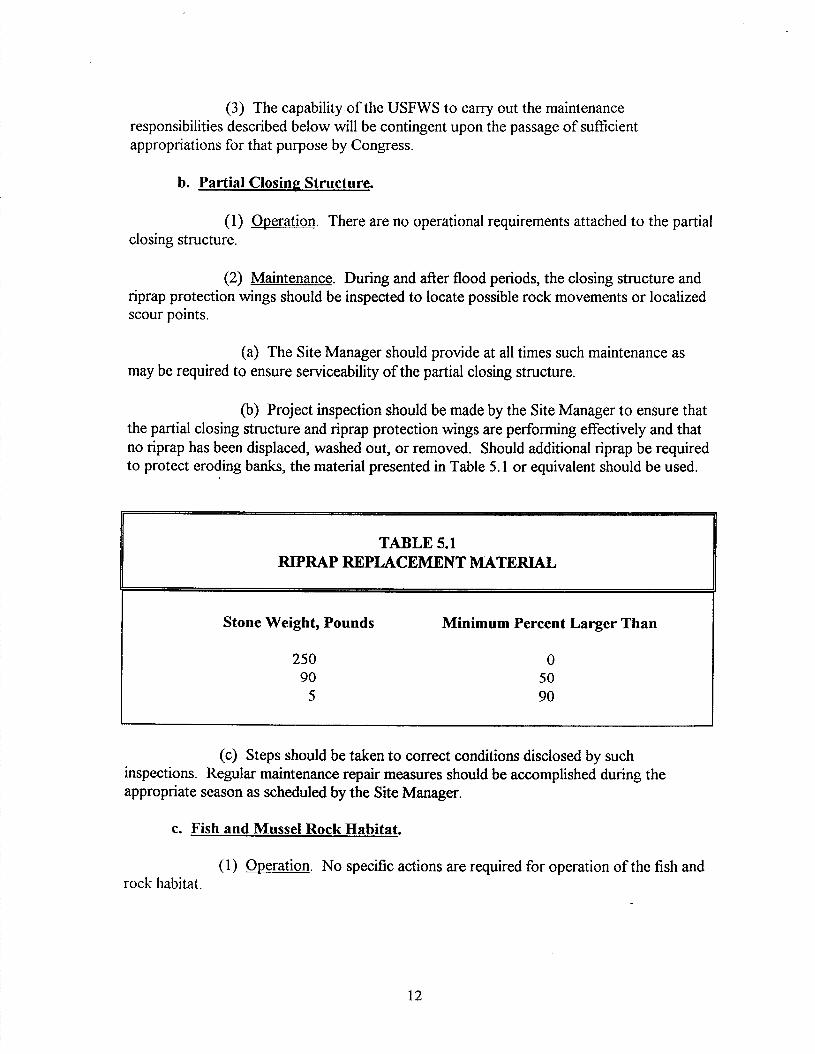
(b) Project inspection should be made by the Site Manager to ensure that the partial closing structure and riprap protection wings are performing effectively and that no riprap has been displaced, washed out, or removed. Should additional riprap be required to protect eroding banks, the material presented in Table 5.1 or equivalent should be used.
TABLE 5.1 RIPRAP REPLACEMENT MATERIAL
Stone Weight, Pounds
250 90
5
Minimum Percent Larger Than
0 50 90
(c) Steps should be taken to correct conditions disclosed by such inspections. Regular maintenance repair measures should be accomplished during the appropriate season as scheduled by the Site Manager.
c. Fish and Mussel Rock Habitat.
(1) Oneration. No specific actions are required for operation of the fish and rock habitat.
12

(2) Maintenance. ’
(a) Inspection. The fish and mussel rock habitat should be inspected for serviceability and accumulation of debris which impacts the hydraulic capacity of the channel. The side slope riprap should be inspected for movement or localized erosion damage.
(b) Maintenance. No maintenance of the fish and mussel rock habitat channel was anticipated during the planning and design phases of the project. If inspections reveal an accumulation of debris impacting the hydrauhc capacity of the channel, the USFWS and the Corps will mutually agree whether the required repair constitutes minor unanticipated maintenance or if it constitutes major rehabilitation and is a Corps responsibility per Section 7, p. 14.
d. McCartney Lake Dredhg.
(1) Operation. There are no operational requirements attached to this project component.
, (2) Maintenance.
(a) Insnection. The dredge cuts in McCartney Lake should be inspected visually and by sufficient pole soundings.
(b) Maintenance. No maintenance of the McCartney Lake dredge cuts was anticipated during the planning and design phases of the project. Unanticipated siltation of the McCartney Lake dredge cut to the degree warranting maintenance dredging would be considered major rehabilitation per Section 7, p. 14.
e. Confined Dredged Material Placement Site.
(1) Oneration. There are no operational requirements attached to this project component.
(2) Maintenance.
(a) Insnection. Project inspections of the dredged material placement site should be made by the Site Manager to record usage of the site consistent with management practices.
(b) Maintenance. No maintenance of the dredged material placement site is required.
’ Responsibility for maintenance of the fish and mussel habitat structures shall be in accordance with previous agreements between the USFWS and the WDNR.
13

6. PERFORMANCE MONITORING AND ASSESSMENT.
a. The purpose of this section is to summarize monitoring and data collection aspects of the project. Table 6.1 presents the principal types, purposes, and responsibility of monitoring and data collection. Table 6.2 provides a summary of actual monitoring and data parameters grouped by project phase, responsible agency, and data collection intervals. Changes to the monitoring plan should be coordinated with the USFWS, the WDNR, and the U.S. Army Corps of Engineers.
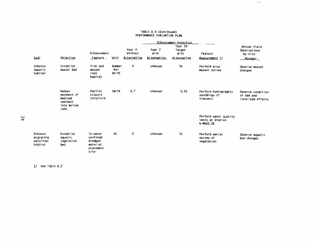
b. Table 6.3 presents the post-construction performance evaluation plan. The monitoring parameters were developed to measure the effectiveness of the stated goals. The Site Manager should follow Table 6.3, as shown, to make annual field observations. The annual field observations and the quantitative monitoring parameters will form the basis of project evaluation.
7. PROJECT REHABILITATION OR ABANDONMENT
a. As stated in the Memorandum of Agreement between the USFWS and the Corps, the Corps will be responsible for any mutually agreed upon repair and rehabilitation of the Bet-tom and McCartney Lakes project that exceeds the annual maintenance requirements and that may be needed as a result of a specific storm or flood. The project will be inspected as previously described, following flood events or specific storms.
b. Should inspection of the project area following a major flood or natural disaster disclose substantial damage to any of the major components of the project that appears to exceed the annual operation and maintenance as specified in this manual and the Definite Project Report, the Corps and the USFWS should meet and discuss the appropriate course of action in light of the original project design. The inspections by the District Manager (as summarized in the submittal checklist) and the joint inspections with the Corps will be the basis for determining maintenance responsibility by the USFWS versus potential rehabilitation by the Corps. Repair of damage attributable to lack of maintenance is a USFWS responsibility. The options of rehabilitation or abandonment of the project may be considered at this time. Any decision would be carried forth only upon written mutual agreement of the USFWS and the Corps. Included in such agreement would be a description of the agreed upon course of action and funding responsibilities, if any.
14

.
Baseline Monitoring
Data Collection
TABLE 6.1 MONITORING AND PERFORMANCE EVALUATION MATRIX
reject Type of hase Activity Purpose
Responsible Agency
Implementing Agency
Funding Source
Implementation Instructions
re- reject
Sedimentation Problem Analysis
Pre-project Monitoring
System-wide problem definition. Evaluates planning assumptions.
Identifies and defines problems at HREP site. Establishes need of proposed project features.
WDNR USFWS LTRM 11 -- (EMTC)
WDNR USFWS USFWS --
Establishes baselines for performance evaluation.
corps Field station or sponsor LTRM See Table 6.2. thru Cooperative Agree- ments or Corps.
resign Includes quantification of project objectives, design of project, and development of performance evaluation plan
corps corps HREP 21 See Table 6.2.
:onstruction Construction Monitoring
Assesses construction impacts; assures permit conditions are met.
corps corps HREP See State Section 401 Stipulations.
‘ost 1onstruction
Performance Evaluation Monitoring
Determines success of project as related to objectives.
corps (quan- titive) sponsor (Field Observations)
Field station or sponsor thru Cooperative Agreement, sponsor thru O&M, or Corps.
LTRM See Table 6.3.
Analysis of Biological Responses
Evaluates predictions and assumptions of habitat unit analysis. Studies beyond scope of performance evaluation, or if projects do not have desired biological results.
USFWS USFWS LTRM __ (EMTC)
./ Long-Term Resource Monitoring of the Environmental Management Program (P.L. 99-662). ;/ Habitat Rehabilitation and Enhancement Project of the Environmental Management Program (P.L. 99-662).

TABLE 6.2 RESOURCE MONITORING AND DATA COLLECTION SUMMARY
WATER QUALITY DATA Pre- Post
I Proiect Design Const.
TYPE MEASUREMENT I Phase Phase Phase i APR- OCT- APR- OCT- APR- OCT- SEP MAR SEP MAR SEP MAR
POINT MEASUREMENTS
Station W-M600.3C Turbidity Secchi Disk Transparency - Dissolved Oxygen Specific Conductance Water Temperature Velocity Water Depth Water Elevation Ice Depth
2w 1M 2u 1n 2U 1M 2W 1M 2u 1M 2U 1M 2u 1M 2bi 1M
1M 1M
2u 1M 2u 1M 2u 1M 2W 1M
Snou Depth Total Alkalinity
PH Chlorophyll Suswnded Solids Uind Direction 2U 1M Vinci Velocity 2U 1M Uave Height 2u 1M Cloud Cover 2U 1M
ENGINEERING DATA Pre- Post.
Project Design Const. Phase Phase Phase
NATURAL RESWRCE DATA Pre- Post.
Project Design Const. Phase Phase Phase
Corps UDNR #20 -I-

TABLE 6.2 (Continued) RESOURCE MONITORING AND DATA COLLECTION SWUARY
TYPE MEASUREMENT
Stations W-M599.5D, W-M599.2C
Turbidity Secchi Disk Transparency Dissolved Oxygen Specific Conductance Water Temperature
# Velocity 4 Water Depth
Water Elevation
UATER QUALITY DATA I ENGINEERING DATA I NATURAL RESWRCE DATA PI-p- Post I Pre- Post. I Pre- Post. . ._
Project Design cohst. Phase Phase Phase
APR- OCT- APR- OCT- APR- OCT- SEP MAR SEP MAR SEP MAR
Project Design Const. Phase Phase Phase
Project Design Const. Phase Phase Phase
I Sampling Agency Remarks
I corPs I wDNR#20 I 2w 1M 2u 1M 2u 1M 2u 1M 2u 1M 2w 1H 2u 1n 2u 1M
In 1M
2u 1M 2w 1M 2u 1M 2u 1M 2u 1M 2u 1M 2u 1M 2u 1H

TABLE 6.2 (Continued) RESOURCE MONITORING AND DATA COLLECTION SUMMARY
UATER PUALITY DATA I ENGINEERING DATA I NATURAL RESWRCE DATA Pre- Post Pre- Post. Pre- Post.
Project Design Const. Project Design Const. Project Design Const.
TYPE MEASUREMENT Phase Phase Phase 1 Phase Phase Phase Phase Phase Phase
APR- OCT- APR- OCT- APR- OCT- SEP MAR SEP MAR SEP MAR Sarrpling
Stations W-598.9E, W-M599.8B
Turbidity Secchi Disk Transparency Dissolved Oxygen Specific Conductance Uater Temperature Velocity Uater Depth Uater ELevation Ice Depth Snow Depth Total Alkalinity
PH Chlorophyll Suspended Solids Wind Direction Uind Velocity Wave Height Cloud Cover
2u 1n 2h' 1M 2u 1n 2U 1M 2U 1M 2u 1M 2u 1M 2U 1M
1M 1M
2u 1M 2u 1M 2u 1M 2u 1M 2u 1M 2u 1M 2u 1M 2U 1M
corps 22
(Springfed sites)

TABLE 6.2 (Continued) RESOURCE MDNITORING AND DATA COLLECTION SUMMARY
WATER PUALITY DATA ENGINEERING DATA NATURAL RESOURCE DATA
Pre- Post Pre- post. Pre- post. Project Design Const. Project Design Const. Project Design Const. Phase Phase Phase Phase Phase Phase Phase Phase Phase
TYPE MEASUREMENT APR- OCT- APR- OCT- APR- OCT- SEP MAR SEP MAR SEP MAR Sampling
Agency Remarks
&$JQR W-M602.2E WNDR #34
Velocity Water Depth Water Elevation suspended Solids
StatiQD6/ Corps Bulk Sediment Analysis 1
llaripni!/ Corps Elutriate Analysis 1 -
SbtiQD8/ Corps Ambient Uater Analysis 1 -
S..wiQOP/ Corps Colum Setting Analysis 1
statipn U-M600.5C UDNR H)NR #la Dissolved Oxygen 7c - 7c - (rock) Yater Temperature 7c - 7c -
statipo u-M60l.OH WNR IJDNR #2 Dissolved Oxygen 7c - (channel Uater Teqxrature 7c - above
rock) Light Data
m U-M600.3C Dissolved Oxygen Uater Temperature
F-H
fish Structwes Perform Condition Survey
7c -
7c - UDNR hDNR #20 7c -
X X X ClDNR Need VDNR Input
Corps 5Y

TABLE 6.2 (Continued) RESCURCE MONITORING AND DATA COLLECTfON SUMMARY
WATER DUALITY DATA ENGINEERING DATA NATURAL RESOURCE DATA Pre- Post Pre- post. Pre- post.
Project Design Const. Project Design Const. Project Phase
Design Const. Phase Phase Phase Phase Phase Phase Phase Phase
TYPE MEASUREMENT APR- OCT- APR- OCT- APR- OCT- SFP MAR SEP MAR SEP MAR Sampling
Agency Remarks TRANSECT MEASUREMENTS
Transects 21 Hydrographic Soundings SY
corps
TranSectS 31 ProfiLe SY
Corps
rransectsW Hydrographic Soundings SY
Corps
Transectsv Vegetation Survey SY
AREA MEASUREMENTS Corps
Fish at-d Mussel Habitat Area Mussel M-M602.1C Survey
Corps SY
Bertom/HcCartney Lake VerticaI Stereo
Corps 1
Aerial Photography SY
(1:SDOO)
U = UEEK, 2U = ONCE EVERY TWO WEEKS M = MONTH Y = YEAR, SY = ONCE EVERY FIVE YEARS
nU = n-UEEK INTERVAL nY = n-YEAR INTERVAL
1,2,3,--- q NUMBER OF TIMES DATA IS COLLECTED UITHIN DESIGNATED PROJECT PHASE c = CONTINUOUS
1,2.3. . ..nC = x-DAY CONTINUOUS

TABLE 6.2 FOOTNOTES
Y Post Construction monitoring sites/transects are shown on Plates 1 and 2. See the DPR for Pre-Project and Design Phase station locations. The following monitoring was performed by the Corps of Engineers/Construction Contractor during the construction phase for the purpose of meeting Permit requirements.
Station Frequency
Dredge C&e Water Inside of Disc& Weir Suspended Solids 3/w* Dissolved Oxygen 3/w Temperature 3/w PI-I 3/w Ammonia Nitrogen 3/w
500 Feet Doa of Disclmge of Weir Suspended Solids 3/w Dissolved Oxygen 3/w Temperature 3/w PH 3/w Ammonia Nitrogen 3/w
Suspended Solids Dissolved Oxygen Temperature PH
w** W W W
Transects (Lake Dredging)
S-M60 1.2B SM600.8B S-M600.2B S-M599.6B
DPR T13 DPR T16 DPR T19 DPR T23
Transects (Substrate Channel)
S-M602.1 G S-M602.1D
DPR EE DPR FF

Transects (Bertom Lake)
S-M602.1 J S-M602.2J S-M602.3B SM602.2B S-M602.OB
Transects (Aquatic Bed)
DPR DD DPR CC DPR TO DPR T2 DPR T6
V-M599SB DPR T26 V-M599.2B DPR T28
Stations (Design Phase Bulk Sediment Analysis)
DPR BM-1 DPR BM-2 DPR BM-4 DPR BM-5 DPR ML-l DPR ML-2 DPR ML-3
Stations (Design Phase Elutriate Analysis)
Station (Ambient Water Analysis)
Stations (Column Settling Analysis)
DPR ML- 1 DPR ML-2 DPR ML-3
DPR BM-1 DPR M-l
DPR BM88-6- 1 DPR BM88-6-2
* 3/W = three per week ** W = one per week
22

Enhancement Iective Feature !+!niX
Enhance aquat i c habitat
Improve McCartney mg/L dissolved Lake dredging oxygen concentration during critical seasonal stress periods
Enhance Restore deep aquatic (2 6 feet)
Q habitat aquatic habitat *,
Restore tentic lotic habitat access cross- sectional area
Increase rock substrate aquat i c habitat
McCartney Lake
dredging
McCartney Lake
dredging
Fish and mussel rock
AC-F1 0 250
SP-FT 300 not measured
SP-YD D partial Ly 10,000 measured
TABLE 6.3 PERFORMANCE EVALUATION PLAN
Enhancement Potential Year 50
Year 0 Year 2 Target Without Uith Uith
Alternatiw ALternative AltPrnatlVP
(5.0 25.0 >5.0
1800
Feature Measurementl/
Perform water quality tests at Stations W-M600.3C, U-M598.9E, wM599.8B
Perform hydrographic soundings
Perform hydrographic soundings
Perform profite of rock substrate transect
Annual Field Observations
by Site aer
Observe aquatic life changes (i.e., fish kills, sport fishing)
Observe sedimentation effects by pole soundings or depth gauging
Observe sedimentation erosion changes
Observe changes in rock substrate (i.e., movement, sedimentation, organic growth)
i
. lective
Enhance aquat i c habitat
Establish mussel bed
Reduce movement of bedload sediment into Bertcm Lake
Enhancement
Feature
Fish and mussel rock habitat
Partial closure structure
TABLE 6.3 (Continued) PERFORMANCE EVALUATION PLAN
nt Potential Year 50
Year 0 Year 2 Target Vi thout Uith Uith Feature
!&~i..t Alternative Alternative Alternative Measurementl/
N&r Per
SP-YD
0 Unknoun 10 Perform area mussel survey
I N/YR 0.7
Enhance migrating uaterfowl habitat
Establish aquatic vegetation bed
In-uater confined dredged material placement site
AC 0
Unknown
Unknown
Annual Field Observations
by Site
aer
Observe mussel changes
0.55 Perform hydrographic Observe condition soundings of of dam and transect localized effects
10
Perform uater quality tests at Station U-M602.2E
Perform aerial survey of vegetation
Observe aquatic bed changes
1/ See Table 6.2

APPENDIX A
OPERATION, MAINTENANCE, AND REHABILITATION AGREEMENT

United States Department of the Interior FISH AND WILDLIFE SERVlCE RMIuLBuQoIEoo,FoRlSNauw
TWIN -9. MMNESOTA 53111
NS/ARW NOV21 1m
Colonel John R. Brown Dintrlct Engineer U.S. Army Engineer District, Rock Island Clock Tower Building Rock Island, Illinois 61204-2004
Dear CoIoneI Brown:
Enclosed is the signed Rcmorandum of Agreement (Agreement) for the Bertom and McCartney Iakes rehabilitation and enhancement project. While this Agreement has been signed in support of the Environmental Management Program, it should be pointed out that the Fish and Wildlife Service (Service) will handle the operation and maintenance responslbllitles as outlined la the Upper l¶lssisslppl River System - Emlronmental Management Program Fourth AnnuaI Addendum, which differs with Section B of the enclosed agreement. The Addendum outlines the procedure agreed to by the Service and General Van der EIs which basically states: 1) for projects on National Wildlife Refuge lands, the Servlce~wlll assume all operation and maintenance responslblllties and, 2) for projects on General Plan lands where the Service has entered into an agreement with a State, the State should continue to be responsible for operation and maintenance.
Sincerely,
Enclosure
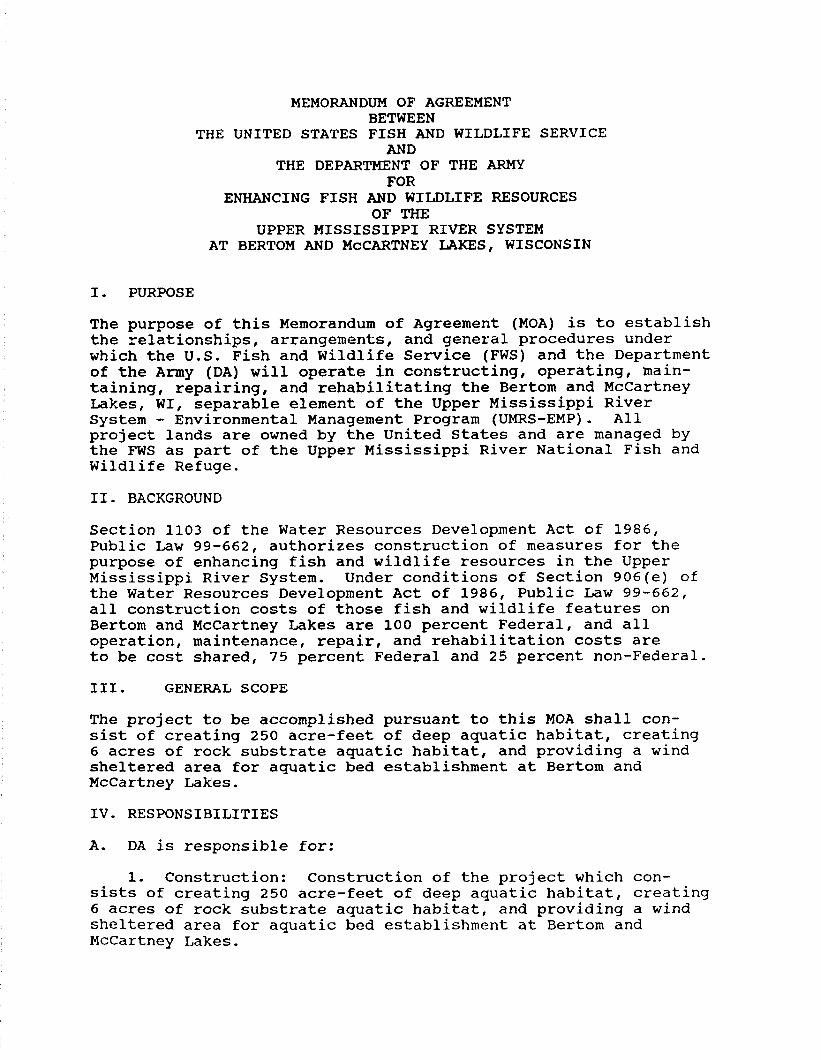
MEMORANDUM OF AGREEMENT BETWEEN
THE UNITED STATES FISH AND WILDLIFE SERVICE AND
THE DEPARTMENT OF THE ARMY FOR
ENHANCING FISH AND WILDLIFE RESOURCES OF THE
UPPER MISSISSIPPI RIVER SYSTEM AT BERTOM AND MCCARTNEY LAKES, WISCONSIN
I. PURPOSE
The purpose of this Memorandum of Agreement (MOA) is to establish the relationships, arrangements, and general procedures under which the U.S. Fish and Wildlife Service (FWS) and the Department of the Army (DA) will operate in constructing, operating, main- taining, repairing, and rehabilitating the Bertom and McCartney Lakes, WI, separable element of the Upper Mississippi River System - Environmental Management Program (UMRS-EMP). All project lands are owned by the United States and are managed by the FWS as part of the Upper Mississippi River National Fish and Wildlife Refuge.
II. BACKGROUND
Section 1103 of the Water Resources Development Act of 1986, Public Law 99-662, authorizes construction of measures for the purpose of enhancing fish and wildlife resources in the Upper Mississippi River System. Under conditions of Section 906(e) of the Water Resources Development Act of 1986, Public Law 99-662, all construction costs of those fish and wildlife features on Bertom and McCartney Lakes are 100 percent Federal, and all operation, maintenance, repair, and rehabilitation costs are to be cost shared, 75 percent Federal and 25 percent non-Federal.
III. GENERAL SCOPE
The project to be accomplished pursuant to this MOA shall con- sist of creating 250 acre-feet of deep aquatic habitat, creating 6 acres of rock substrate aquatic habitat, and providing a wind sheltered area for aquatic bed establishment at Bertom and McCartney Lakes.
IV. RESPONSIBILITIES
A. DA is responsible for:
1. Construction: Construction of the project which con- sists of creating 250 acre-feet of deep aquatic habitat, creating 6 acres of rock substrate aquatic habitat, and providing a wind sheltered area for aquatic bed establishment at Bertom and McCartney Lakes.

2. Major Rehabilitation: Any mutually agreed upon rehabilitation of the project that exceeds the annual operation and maintenance requirements identified in the Definite Project Report and that is needed as a result of specific storm or flood events.
3. Construction Management: Subject to and using funds appropriated by the Congress of the United States, DA will construct the Bertom and McCartney Lakes Fish and Wildlife Enhancement Project as described in the Definite Project Report, "Bertom and McCartney Lakes Rehabilitation and Enhancement," dated June 1989, applying those procedures usually followed or applied in Federal projects, pursuant to Federal laws, regu- lations, and policies. The FWS will be afforded the opportunity to review and comment on all modifications and change orders prior to the issuance to the contractor of a Notice to Proceed. If DA encounters potential delays related to construction of the project, DA will promptly notify FWS of such delays.
4. Maintenance of Records: DA will keep books, records, documents, and other evidence pertaining to costs and expenses incurred in connection with construction of the project to the extent and in such detail as will properly reflect total costs. DA shall maintain such books, records, documents, and other evidence for a minimum of three years after completion of con- struction of the project and resolution of all relevant claims arising therefrom, and shall make available at its offices at reasonable times, such books, records, documents, and other evidence for inspection and audit by authorized representatives of the FWS.
B. FWS is responsible for:
1. Operation, Maintenance, and Repair: Upon completion of construction as determined by the District Engineer, Rock Island, the FWS shall accept the project and shall operate, maintain, and repair the project as defined in the Definite Project Report entitled "Bertom and McCartney Lakes Rehabilitation and Enhancement," dated June 1989, in accordance with Section 906(e) of the Water Resources Development Act, Public Law 99-662.
2. Non-Federal Responsibilities: In accordance with Section 906(e) of the Water Resources Development Act, Public Law 99-662, the FWS shall obtain 25 percent of all costs associated with the operation and maintenance of the project from the Wisconsin Department of Natural Resources.

v. MODIFICATION AND TERMINATION
This MOA may be modified or terminated at any time by mutual agreement of the parties. Any such modification or termination must be in writing. Unless otherwise modified or terminated, this MOA shall remain in effect for a period of no more than 50 years after initiation of construction of the project.
VI. REPRESENTATIVES
The following individuals or their designated representatives shall have authority to act under this MOA for their respective parties:
Fws: Regional Director U .S. Fish and Wildlife Services Federal Building, Fort Snelling Twin Cities, Minnesota 55111
DA: District Engineer U.S. Army Engineer District, Rock Island Clock Tower Building - P.O. Box 2004 Rock Island, Illinois 61204-2004
VII. EFFECTIVE DATE OF MOA
This MOA shall become effective when signed by the appropriate representatives of both parties.
THE DEPARTMENT OF THE ARMY THE U.S. FISH AND WILDLIFE SERVICE
District Engineer U.S. Army Engineer District,
Rock Island Corps of Engineers
Regional Direct0 U.S. Fish and Wildlife
Service

APPENDIX B
SITE MANAGER’S
PROJECT INSPECTION AND MONITORING RESULTS

OPERATION AND MAINTENANCE MANUAL BERTOM AND MCCARTNEY LAKES REHABILITATION AND ENHANCEMENT
UPPER MISSISSIPPI RIVER ENVIRONMENTAL MANAGEMENT PROGRAM
POOL 11, RIVER MILES 599 THROUGH 603 GRANT COUNTY, WISCONSIN
SITE MANAGER’S PROJECT INSPECTION AND MONITORING RESULTS
Inspected by Date
Type of Inspection: ( ) semi-annual
1. PROJECT INSPECTION.
a. Partial ClosinP Structure
( ) Wavewash, scouring ( ) Overtopping erosion ( ) Displaced/missing riprap ( ) Burrowing animals ( ) Encroachments
b. Fish and Mussel Rock I%&&
( ) Displaced/missing riprap
( ) emergency-disaster ( ) other
( ) Blockage of inlet and outlet channels ( ) Erosion adjacent to rock substrate ( ) Concrete pipe condition ( ) Lunker fish structures condition
c. McCartnev Lake Dredging
( ) Sedimentation/erosion changes
d. Confined Dredged Material Placement Site
( ) Waste materials/unauthorized structures ( ) Bank erosion
B-l

2. PROJECT MONITORING.
a. Partial Closiu Structure
( ) Sediment changes in Bertom Lake
b. Fish and Mussel Rock Habitat
( ) Sedimentation/erosion changes ( ) Changes in rock substrate ( ) Presence of mussels ( ) Fishery usage of fish structures
c. McCartnev Lake Dreb
( ) Fish population/species changes
d. Dredged Mater-Placement Site
( ) Specie usage
Site Manager
B-2

APPENDIX C
DISTRIBUTION