
Bentley Civil Workshop - MX AssociationThe V8i SELECTseries 3 release of Bentley Civil software uses...
92
Bentley Civil Workshop 2012 BE Together BC4WK6, BC4WK7, BC4WK10 Moving to SELECTseries 3 for Bentley Civil Users BC4WK6 (InRoads) Team Leader: Mike Cavanaugh BC4WK7 (GEOPAK) Team Leader: Lou Barrett BC4WK10 (MX) Team Leader: Ian Rosam Bentley Systems, Incorporated 685 Stockton Drive Exton, PA 19341 www.bentley.com
Transcript of Bentley Civil Workshop - MX AssociationThe V8i SELECTseries 3 release of Bentley Civil software uses...

Bentley Civil Workshop
2012 BE Together
BC4WK6, BC4WK7, BC4WK10
Moving to SELECTseries 3 for Bentley Civil Users
BC4WK6 (InRoads) Team Leader: Mike Cavanaugh
BC4WK7 (GEOPAK) Team Leader: Lou Barrett
BC4WK10 (MX) Team Leader: Ian Rosam
Bentley Systems, Incorporated 685 Stockton Drive Exton, PA 19341 www.bentley.com

This page left intentionally blank.
Workshop: BC4WK6, BC4WK7, BC4WK10 - Moving to SELECTseries 3 for Bentley Civil Users i
Copyright © 2012 Bentley Systems, Inc.
Table of Contents
Preface ............................................................................................................... 1
Chapter 1: Moving From SELECTseries2 to SELECTseries 3................................ 3
Overview ........................................................................................................................................ 3
What Do We Mean By Model-Centric? ............................................................................................ 3
Data Sharing vs. File Sharing ............................................................................................................ 4
Using the Design File As a Container For Data ................................................................................ 4
SELECTseries 2 and SELECTseries 3 Workflows ............................................................................... 5 SELECTseries 3 ........................................................................................................................ 6 Survey / Mapping ................................................................................................................... 7 Planning ................................................................................................................................. 8 Design .................................................................................................................................... 9 Beyond SELECTseries 3 – Civil Information Model .............................................................. 10 Evolution of Civil Model to Information Mobility ................................................................ 11
How to Transition From SELECTseries 2 to SELECTseries 3 ........................................................... 12
SELECTseries 2 to SELECTseries 3 or Both? ................................................................................... 12
Installation ..................................................................................................................................... 12
Advance Preparation ..................................................................................................................... 12
Chapter Summary .......................................................................................................................... 13
Chapter 2: Workspace Configuration .................................................................. 15
Overview ...................................................................................................................................... 15
New Configuration Variables ......................................................................................................... 15 Exercise: Check Workstation / Laptop Settings ....................................................... 17 Exercise: Review Configuration Variables ................................................................ 19
Chapter Summary .......................................................................................................................... 19
Chapter 3: Basics of DGN Libraries .................................................................... 21
Overview ...................................................................................................................................... 21
Text Styles ...................................................................................................................................... 21 Exercise: Create Text Style ....................................................................................... 21
Element Templates ........................................................................................................................ 23 Exercise: Create Element Templates ........................................................................ 23
Using Standards ............................................................................................................................. 25 Exercise: Display Terrain Model ............................................................................... 25
Chapter Summary .......................................................................................................................... 26

Table of Contents
ii Workshop: BC4WK6, BC4WK7, BC4WK10 - Moving to SELECTseries 3 for Bentley Civil Users
Copyright © 2012 Bentley Systems, Inc.
Chapter 4: Project Explorer .................................................................................. 27
Overview ...................................................................................................................................... 27 Exercise: Tour of Project Explorer ............................................................................. 27
Chapter Summary .......................................................................................................................... 28
Chapter 5: Linking Legacy Settings..................................................................... 29
Overview ...................................................................................................................................... 29 Exercise: Link Active Styles........................................................................................ 29 What happened - Inroads? ................................................................................................... 30 What happened - GEOPAK? ................................................................................................. 31 What happened? - MX ......................................................................................................... 32
Linking Survey Styles ...................................................................................................................... 33 Link Survey Styles to DGNLib .................................................................................... 33
Chapter Summary .......................................................................................................................... 34
Chapter 6: Working With Features ....................................................................... 35
Overview ...................................................................................................................................... 35
Managing Features ......................................................................................................................... 35 Working with Features .............................................................................................. 35
Chapter Summary .......................................................................................................................... 42
Chapter 7: Seed Files ............................................................................................ 43
Overview ...................................................................................................................................... 43
Project Description ......................................................................................................................... 43
Geographic Coordinate Systems .................................................................................................... 43 Exercise: Assign Geographic Coordinate System ...................................................... 43
Annotation Scale ............................................................................................................................ 45 Exercise: Assign Annotation Scale ............................................................................. 45
Civil Formatting Options ................................................................................................................ 46 Settings > Design Files > Civil Formatting ............................................................................. 46 Exercise: Review and Modify Civil Formatting Options ............................................ 49 Workspace > Preferences > Civil Formatting ....................................................................... 49 Exercise: Review and Modify the Preferences > Civil Formatting Options ............... 52
Chapter Summary .......................................................................................................................... 52
Chapter 8: Standards ............................................................................................ 53
Overview ...................................................................................................................................... 53
Design Standards ............................................................................................................................ 53 Group Exercise: Review Design Standards ................................................................ 54 Create a New Vertical Standard ................................................................................ 56 Create a New Horizontal Standard ........................................................................... 57 Verify the Results of the New Standards .................................................................. 58
Superelevation Preferences ........................................................................................................... 58

Table of Contents
Workshop: BC4WK6, BC4WK7, BC4WK10 - Moving to SELECTseries 3 for Bentley Civil Users iii
Copyright © 2012 Bentley Systems, Inc.
Appendix A: Setting Up the Workshop in Your Office ......................................... 61
Overview ...................................................................................................................................... 61 Exercise: Copy the Dataset to Your Computer ........................................................ 61 Exercise: Check Workstation / Laptop Settings ....................................................... 61
Appendix B: Export to Native .................................................................................. 65
Overview ...................................................................................................................................... 65
Description ..................................................................................................................................... 65
WHY EXPORT to Native? ................................................................................................................ 65
Setup ...................................................................................................................................... 65
How it Works ................................................................................................................................. 66
Best Practices ................................................................................................................................. 67
Appendix C: Graphical Filter Library ..................................................................... 69
Overview ...................................................................................................................................... 69
Graphical Filters ............................................................................................................................. 69
Update Terrain from Source .......................................................................................................... 69
Graphical Filter Tasks ..................................................................................................................... 70
Appendix D: Civil Report Browser ......................................................................... 73
Overview ...................................................................................................................................... 73
Accessing the Browser ................................................................................................................... 73
Setting the Defaults ....................................................................................................................... 74
Appendix E: MX Workflows..................................................................................... 75
Overview ...................................................................................................................................... 75
Dealing with MX models and Civil Features .................................................................................. 75
Importing MX Geometry ................................................................................................................ 76
Export of MX Geometry ................................................................................................................. 76
MX Log file ..................................................................................................................................... 76
Major Option Script ....................................................................................................................... 77
Import Terrain model. ................................................................................................................... 77
Glossary ............................................................................................................. 79

Table of Contents
iv Workshop: BC4WK6, BC4WK7, BC4WK10 - Moving to SELECTseries 3 for Bentley Civil Users
Copyright © 2012 Bentley Systems, Inc.
This page left intentionally blank.

Workshop: BC4WK6, BC4WK7, BC4WK10 - Moving to SELECTseries 3 for Bentley Civil Users 1
Copyright © 2012 Bentley Systems, Inc.
Preface What does it take to move to Bentley Civil V8i SELECTseries3? What steps do you follow? What is the impact to standards, as well as to managers and end users? This workshop will attempt to answer those questions in a way that will assist organizations in their movement from SELECTseries 2 to SELECTseries 3 functionality. From importing existing feature definitions to the establishment of horizontal and vertical design standards, we have structured the contents of the exercises to allow your interaction with as broad a range of topics as possible. While we may not be able to cover every workflow and possible configuration issue that may be encountered within an organization, we will cover the ‘major’ topics that we feel most organizations will confront.
This workshop is equally applicable for the MX, InRoads or GEOPAK families of products. The majority of topics and exercises are common to all three product lines. Where differences do occur, such as in the importing of existing feature definitions, we will point those differences out and accommodate them within the exercises themselves.
There are more exercises in this manual than we will have time to cover today. We will all complete the basic set of exercises, and for those veteran users in the group who complete them and still have time left in the exercise session, you are welcome to work on the optional. In addition, the workshop guide and dataset is yours to take with you. If you don’t finish all the exercises, or just want to work with the dataset upon return to your office, the datasets (both initial and completed files) are provided on the Conference DVD. Many workshops will also have videos of all exercises on the DVD.
Note: Prerequisite Knowledge Level: Participant should have a basic understanding of civil design and the types of workspace configurations that they require. For example, features, configuration variables, seed files, workspace preferences, etc. They should also be fluent in the use of one of the Bentley Power products or CAD and the native application (MX, InRoads or GEOPAK).

Preface
2 Workshop: BC4WK6, BC4WK7, BC4WK10 - Moving to SELECTseries 3 for Bentley Civil Users
Copyright © 2012 Bentley Systems, Inc.
This page left intentionally blank.
Workshop: BC4WK6, BC4WK7, BC4WK10 - Moving to SELECTseries 3 for Bentley Civil Users 3
Copyright © 2012 Bentley Systems, Inc.
Chapter 1: Moving From SELECTseries2 to SELECTseries 3
OVERVIEW
Bentley Civil software has been integral in the development of the world’s infrastructure for the last 3 decades through the GEOPAK, InRoads and MX product lines. The products and tools themselves have been developed in conjunction with practitioners from around the world to reflect best practices that are both tried and tested. However, aging infrastructure along with economic and legislative influences now require a shift in philosophy that places an increased demand on project delivery for greater efficiency, accountability and sustainable designs. This paradigm shift in project delivery requires an evolution in tools and practices.
With this in mind, the V8i SELECTseries 3 release will be a significant milestone for the Bentley Civil product line. By taking advantage of the benefits offered through technological advances, this release will address the aforementioned project delivery needs by facilitating greater productivity in the design processes, reduced delivery times and distributed team management to aid in the provision of sustainable designs.
The V8i SELECTseries 3 release of Bentley Civil software contains not just new tools but new technology. Developed in line with changes in philosophy to harness the latest hardware and software developments, it integrates CAD and engineering knowledge to create a ‘Better Model’ that can be used throughout the assets lifecycle and address market requirements.
The new and enhanced technology inherent in the V8i SELECTseries 3 release provides us an opportunity to change our philosophy of project deliverables. A user can design a project and not be limited to producing only a traditional paper plan set, but actually produce a deliverable containing an intelligent spatial model. This model can then be utilized downstream of the design not only for project planning and construction, but also throughout the assets life cycle. As with any new release of software, users will of course need to become familiar with enhancements and new technologies. However, the larger issue here is the shift away from a mindset of producing plans to a philosophy of producing an intelligent model, in effect a move to a model-centric design process.
WHAT DO WE MEAN BY MODEL-CENTRIC?
Simply put, a Model-Centric approach facilitates the use of a common data repository that can be used collaboratively throughout the lifecycle by the various interested parties without the need for replication or duplication of data.
The V8i SELECTseries 3 release of Bentley Civil software uses at its core the DGN model. In other words, all civil artifacts such as geometry and surfaces reside in the DGN model. This provides the user multiple benefits.
The DGN model provides a readily consumable graphical format that is open source and accessible through many viewers (Navigator, DWG, 3D PDF, etc.).
Currently, in many cases, civil data must be essentially converted and in some cases requires reverse engineering to be conformed to a usable format that can be used by other disciplines and/or

Data Sharing vs. File Sharing
4 Workshop: BC4WK6, BC4WK7, BC4WK10 - Moving to SELECTseries 3 for Bentley Civil Users
Copyright © 2012 Bentley Systems, Inc.
software. Being able to view and analyze the information directly in the DGN model reduces the error prone process of conversion and reduces lead in time.
Civil software has progressed from a simple drafting toolset, to more sophisticated drawing capabilities, to design, survey, hydraulics and other functionally specific toolsets as adjuncts. With advances in technology in the last decade (both hardware and software for design and construction), we have an opportunity to move from adjuncts to integration; a Civil software solution where users can perform workflows efficiently, with the results perpetuated throughout the project.
DATA SHARING VS. FILE SHARING
As we mentioned earlier, with traditional projects that utilize external proprietary databases and formats, it is a common requirement that project information is provided to external sources (such as a contractor, consultant, clients, etc.) who may not utilize the same software in which the data was created. In addition, a typical civil project is comprised of numerous disciplines needing to share data as well (e.g. survey, civil, structural, hydraulic, geological, etc.).
The data on a civil project typically include a variety of formats covering multiple disciplines. This includes traditional CAD design files that are interconnected via reference files. In addition, a variety of auxiliary files exist that pertain to various aspects of the project. Examples include files for existing and proposed terrain models as well as files that pertain to roadway and structural components, survey, ponds, park and rides, geotechnical databases and hydraulic files, just to name a few.
However, with V8i SELECTseries 3, the fundamental shift from file sharing to data sharing has begun with the elimination of proprietary files and specialized formats. For example, the terrain model moves out of a proprietary, binary formatted file and into a DGN Model as a MicroStation element that can be referenced to any other design file. Horizontal and vertical geometry also move out of proprietary databases and into a DGN model. The tools draw “smart” geometric graphics which enable easy modification and manipulation and can be targeted and consumed by other civil tools. Finally, the proposed surface model itself moves out of a propriety formatted file and into the DGN model, allowing for the first time the cutting of dynamic sections directly from 3D elements.
USING THE DESIGN FILE AS A CONTAINER FOR DATA
By shifting the storage of data from historical proprietary external data files into a common openly accessible design file, the typical issues encountered with traditional file sharing diminish. However the data still needs to be managed and shared with both internal and external parties in an efficient manner. Some parties need only consume the data, so that viewing capabilities are the only requirement. Other parties need to interact and in some cases modify the data. The use case for data sharing need to be considered to ensure project team members have the ability to modify data, without infringing on other team members. Topics including how to avoid any accidental deletion or modification of data are also warranted. While current workflows have accounted for these scenarios, they need to be revisited as the technology and Civil solutions change.
The container methodology also enables review and packaging of a project for external partners or management review. It can be utilized within ProjectWise or in a Windows environment.
The container methodology will accomplish several objectives:
Other project team members have the data readily accessible. Project team members only go to one location as a source of data. Project team members can update the data as needed in a centralized location. When using reference files, files can be read only which avoids accidental deletion.
SELECTseries 2 and SELECTseries 3 Workflows
Workshop: BC4WK6, BC4WK7, BC4WK10 - Moving to SELECTseries 3 for Bentley Civil Users 5
Copyright © 2012 Bentley Systems, Inc.
SELECTSERIES 2 AND SELECTSERIES 3 WORKFLOWS
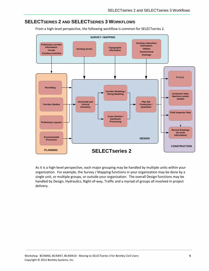
From a high-level perspective, the following workflow is common for SELECTseries 2.
Horizontal and
Vertical
Geometry
SELECTseries 2
Corridor Modeling /
String Modeling
Cross Section /
Earthwork
Processing
Plan Set
Production /
Quantities
Contractor Data:
Machine control
models
Existing terrain
Preliminary corridor
information:
Terrain
Existing centerline
Existing subsurface
information:
Utilities
Geotechnical
Drainage
Topographic
information
Corridor Studies
P S & E
Field Inspector Data
Record Drawings
(As-built
information)
DESIGN
PLANNING
CONSTRUCTION
SURVEY / MAPPING
Permitting
Environmental
Processes
Preliminary Layouts
As it is a high-level perspective, each major grouping may be handled by multiple units within your organization. For example, the Survey / Mapping functions in your organization may be done by a single unit, or multiple groups, or outside your organization. The overall Design functions may be handled by Design, Hydraulics, Right-of-way, Traffic and a myriad of groups all involved in project delivery.

SELECTseries 2 and SELECTseries 3 Workflows
6 Workshop: BC4WK6, BC4WK7, BC4WK10 - Moving to SELECTseries 3 for Bentley Civil Users
Copyright © 2012 Bentley Systems, Inc.
SELECTSERIES 3
In SELECTseries 3, the groups in white do not have workflow changes, while those in green will see an impact.
SELECTseries 3
Contractor Data:
Machine control
models
Existing terrain
Preliminary corridor
information:
Terrain
Existing centerline
Existing subsurface
information:
Utilities
Geotechnical
Drainage
Topographic
information
Corridor Studies
P S & E
Field Inspector Data
Record Drawings
(As-built
information)DESIGN
PLANNING
CONSTRUCTION
SURVEY / MAPPING
Permitting
Environmental
Processes
Preliminary Layouts
The tool set provided at SELECTseries 3 provides all Bentley Civil products with MicroStation integrated capability and significant productivity gains in the following areas:
New terrain modeling tools that extend the native MicroStation terrain element, providing additional creation, analytical and editing capabilities required by civil workflows. Along with these new functionalities, the user will see significant performance improvements in handling not only much larger terrains, but in displaying and manipulating those terrains as well. Finally, a wider variety of data file formats will be supported than those found in earlier versions.
New civil geometry tools that provide ‘object modeling’ design capabilities for both horizontal and vertical methodologies. These new capabilities give the user the ability to establish rules and relationships between multiple geometric elements, allowing geometry elements to update automatically as changes are made within these relationships. In addition, a new user experience allows for heads up design and editing capabilities. Finally, integration of geometric design standards allows for the population of standards values based on design speeds as well as for immediate error checking and flagging.
Enhanced modeling technology that provides for integrated, dynamic and real time modeling of corridor components, surface models and resulting geometry. An

SELECTseries 2 and SELECTseries 3 Workflows
Workshop: BC4WK6, BC4WK7, BC4WK10 - Moving to SELECTseries 3 for Bentley Civil Users 7
Copyright © 2012 Bentley Systems, Inc.
enhanced model that facilitates better quantities and easier visualization as well as construction simulation and asset management.
In addition to new technology and advancements in the tools sets mentioned previously, traditional workflows will benefit with the implementation of the following important milestones:
A shift in the design process with a focus on data sharing. Traditional workflows depend greatly on file sharing. However, data sharing reduces design errors in multi-disciplined, distributed workflows and provides ease of design review.
The preservation of a user’s design intent provides automatic, intelligent updating of the models and facilitates reduced delivery times as well as reduced potential for errors.
A new user experience provides for design environment enhancements through an intuitive and dynamic interface.
SURVEY / MAPPING
The Survey and Mapping functions will see no changes in the data collection, but will have improvements in processing. The Mapping functions have new and improved tools for Point Clouds, and improved terrain model functionality.
Existing terrain
Preliminary corridor
information:
Terrain
Existing centerline
Existing subsurface
information:
Utilities
Geotechnical
Drainage
Topographic
information
SURVEY / MAPPING
Changes to the workflows include:
Easier processing via drag and drop of data files into Project Graphical editing of data Optional audit trail
Benefits to these workflows include:
Survey field collection – easier editing capabilities Easier hand-off to downstream customers All information is stored in the DGN file Improved terrain model Ability to handle more formats Better reporting
SELECTseries 2 and SELECTseries 3 Workflows
8 Workshop: BC4WK6, BC4WK7, BC4WK10 - Moving to SELECTseries 3 for Bentley Civil Users
Copyright © 2012 Bentley Systems, Inc.
PLANNING
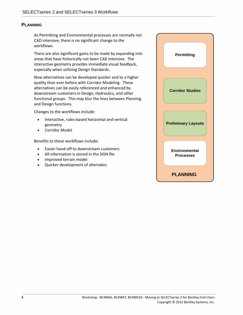
As Permitting and Environmental processes are normally not CAD intensive, there is no significant change to the workflows.
There are also significant gains to be made by expanding into areas that have historically not been CAD intensive. The interactive geometry provides immediate visual feedback, especially when utilizing Design Standards.
Now alternatives can be developed quicker and to a higher quality than ever before with Corridor Modeling. These alternatives can be easily referenced and enhanced by downstream customers in Design, Hydraulics, and other functional groups. This may blur the lines between Planning and Design functions.
Changes to the workflows include:
Interactive, rules-based horizontal and vertical geometry
Corridor Model
Benefits to these workflows include:
Easier hand-off to downstream customers All information is stored in the DGN file Improved terrain model Quicker development of alternates
Corridor Studies
PLANNING
Permitting
Environmental
Processes
Preliminary Layouts

SELECTseries 2 and SELECTseries 3 Workflows
Workshop: BC4WK6, BC4WK7, BC4WK10 - Moving to SELECTseries 3 for Bentley Civil Users 9
Copyright © 2012 Bentley Systems, Inc.
DESIGN
The dramatic upgrades to the Design process include Geometry and Corridor Modeling, Design Intent and automatic, intelligent updating. The 3D Information Model in early stages is the Corridor Model, expanding as organizational needs and resources determine the time frame and level of data information.
DESIGN INTENT
Design intent is the preservation of the rules, relationships and decisions made during the design process. By capturing the intent at its inception, the software can utilize the intent for more intelligent updates, all the while checking against organizational standards.
AUTOMATIC, INTELLIGENT UPDATING
One common problem encountered throughout the design process is when a change is made in one aspect of the project (such as changing a horizontal curve on an alignment), but the designer neglects to carry that change throughout the project. This example would require changes to plan view elements (such as moving edges of pavements and shoulders) and a reprocessing of 3D modeling. In addition, the change in curve may have violated the Design Speed of the project. In SELECTseries 3, the designer can make the alignment modification graphically, which is automatically (but intelligently) reflected in the associated plan view graphics which adjusts the 3D model.
Changes to the workflows include:
Interactive, rules-based horizontal and vertical geometry Corridor Model Design Standards (horizontal and vertical geometry, superelevation)
Benefits to these workflows include:
Easier hand-off to downstream customers All information is stored in the DGN file, with robust support for reference files Improved terrain model
SELECTseries 2 and SELECTseries 3 Workflows
10 Workshop: BC4WK6, BC4WK7, BC4WK10 - Moving to SELECTseries 3 for Bentley Civil Users
Copyright © 2012 Bentley Systems, Inc.
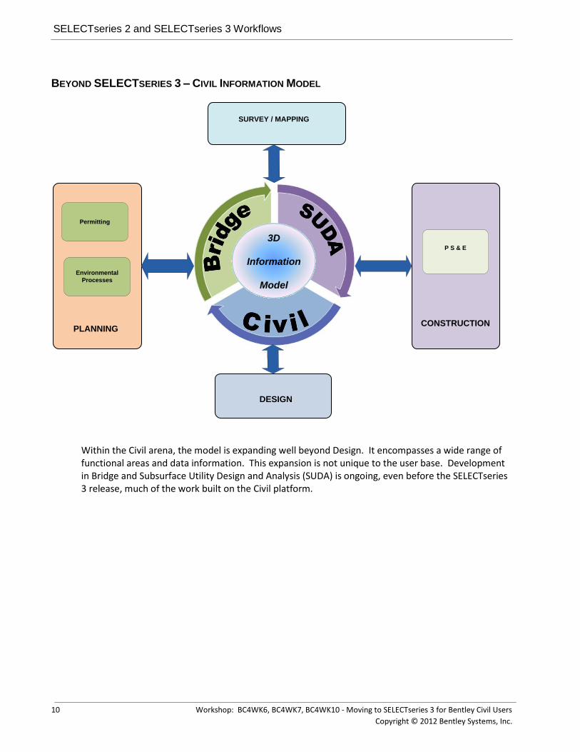
BEYOND SELECTSERIES 3 – CIVIL INFORMATION MODEL
CONSTRUCTION
P S & E
DESIGN
PLANNING
SURVEY / MAPPING
Permitting
Environmental
Processes
3D
Information
Model
Within the Civil arena, the model is expanding well beyond Design. It encompasses a wide range of functional areas and data information. This expansion is not unique to the user base. Development in Bridge and Subsurface Utility Design and Analysis (SUDA) is ongoing, even before the SELECTseries 3 release, much of the work built on the Civil platform.

SELECTseries 2 and SELECTseries 3 Workflows
Workshop: BC4WK6, BC4WK7, BC4WK10 - Moving to SELECTseries 3 for Bentley Civil Users 11
Copyright © 2012 Bentley Systems, Inc.
EVOLUTION OF CIVIL MODEL TO INFORMATION MOBILITY
As we move beyond SELECTseries 3, requirements for information mobility will drive all the processes to evolve and draw down on the benefits the 3D model provides throughout a projects lifecycle.
Bentley’s i-model delivers information mobility, coupled with Projectwise makes true interdisciplinary collaboration a reality throughout a project’s lifecycle, ensuring the same information is used by the right people at the right time.

How to Transition From SELECTseries 2 to SELECTseries 3
12 Workshop: BC4WK6, BC4WK7, BC4WK10 - Moving to SELECTseries 3 for Bentley Civil Users
Copyright © 2012 Bentley Systems, Inc.
HOW TO TRANSITION FROM SELECTSERIES 2 TO SELECTSERIES 3
Transitioning from SELECTseries 2 to SELECTseries 3 can be done in a variety of different methods, based on resources, software utilization, and organizational structure. These include:
Complete enterprise-wide deployment Enterprise-wide deployment but based on geographic locations stretched out over a
period of time Deployment based on functional group (i.e., surveys, planning, design, hydraulics,
etc.) Deployment based on projects (as new projects are started, begin them in
SELECTseries 3) No deployment
SELECTSERIES 2 TO SELECTSERIES 3 OR BOTH?
While doing advance preparation and testing, both SELECTseries 2 to SELECTseries 3 can be installed on the same workstation or laptop. In this way, user support can still be provided for the current software, while testing and set-up is being done.
However, for production, you may want to have only SELECTseries 3 installed. The reasoning is that all the tools currently in SELECTseries 2 are still available in SELECTseries 3. In addition, you have all the new and upgrade tools available at the same time.
INSTALLATION
The installation of any Bentley Civil product is time-consuming, due to sheer size. This has been identified as a major roadblock to deployment, as many organizations are decentralized and have numerous locations where computers need to be loaded. SELECTseries 3 is a complete build, not a service pack or patch. But the good news is that once you have SELECTseries 3 installed, all subsequent installs will be “patch technology” which will dramatically decrease the size of installation packages. The patches are cumulative, meaning that a patch has all the patches issues since the baseline release.
ADVANCE PREPARATION
The changes and new features in V8i SELECTseries3 will require careful planning and preparation. However, many of the tasks can be completed and deployed prior to the actual deployment. In this manner, the system set-up and testing work can be spread out over time, and minimize the impact during actual deployment.
1. Review current MicroStation resources – are they in DGNLibs or can they go there? How are XIN, DDBs and PSS affected?
2. Development of MicroStation element templates (such as for terrain models)
3. Review design standards – validate local standards.
4. Review Design File Settings within Seed Files – Determine default settings for Civil Formatting
5. Review Workspace Preferences – View Options > Civil
6. Superelevation tables – do you have your standards currently set up and in production?
7. New configuration variables – which will be utilized and how to be incorporated?
8. Review reports; determine defaults, deficiencies

Chapter Summary
Workshop: BC4WK6, BC4WK7, BC4WK10 - Moving to SELECTseries 3 for Bentley Civil Users 13
Copyright © 2012 Bentley Systems, Inc.
9. Do you want to create an enterprise-wide or functional group customized task navigator?
10. Review new workflows and determine which areas may be moved forward to new methods.
11. Are there any customized workflows that need to be integrated?
CHAPTER SUMMARY
Now that we have reviewed some of the aspects of moving, let’s look at how we address some of these tasks.

Chapter Summary
14 Workshop: BC4WK6, BC4WK7, BC4WK10 - Moving to SELECTseries 3 for Bentley Civil Users
Copyright © 2012 Bentley Systems, Inc.
This page left intentionally blank.

Workshop: BC4WK6, BC4WK7, BC4WK10 - Moving to SELECTseries 3 for Bentley Civil Users 15
Copyright © 2012 Bentley Systems, Inc.
Chapter 2: Workspace Configuration
OVERVIEW
An important part of being able to control your standards and preferences within an organization is the use of configuration variables. Bentley Civil V8i SELECTseries3 contains several new configuration variables that allow you to control such items as the location of preferences to the specifics of a design tool.
NEW CONFIGURATION VARIABLES
First, let’s look at a complete list of the new Civil configuration variables in SELECTseries 3 with a brief description of each one. Not all of these variables will be set or even used in today’s workshop, but they are all listed here for your convenience.
CONFIGURATION VARIABLE DESCRIPTION
CIVIL_SHOW_MS_PROPERTIES Display extra MS properties that are normally hidden on Civil Elements
CIVIL_STOP_COMMAND_DEFAULTS This stops the Civil commands storing their defaults as xml. Mainly used for Automated testing. Existing files will have to be deleted as it does not stop the system reading them.
CIVIL_DISALLOW_LOCKCHANGES If set to a value of 1, it disallows any lock changes to existing rules. In other words, it prevents a locked rule from being unlocked or an unlocked rule from being locked.
CIVIL_SHOW_SHARED_FEATUREDEF_PROPS
Displays Properties for a Feature Definition that allow you to default all Native or Template Styles to be the same. Useful for setting up Feature Definitions to Element Templates
CIVIL_SUPERELEVATION_RULES_DIRECTORY
Defines the directory to be used as the default location for superelevation preference (SEP/SR) files.
CIVIL_DEFAULTSETTINGS Used to locate the Folder holding the XML file that include the Civil AccuDraw defaults.
CIVIL_DEFAULT_LINEAR_STROKING Defines how often to compute a point or template drop interval location on a tangent segment. This variable is not used by

New Configuration Variables
16 Workshop: BC4WK6, BC4WK7, BC4WK10 - Moving to SELECTseries 3 for Bentley Civil Users
Copyright © 2012 Bentley Systems, Inc.
Corridor Modeling. If not set, the value defaults to 10. This is used when generating 3d elements and the apply Template command.
CIVIL_DEFAULT_PROFILE_STROKING Defines how often to compute a point or template drop interval location along a profile, with extra points being computed based on a chord offset from the profile. The value defines the chord height used to calculate the extra points. If not set, the value defaults to 0.1. This is used in Corridor Modeling when Vertical Curve Densification is applied.
CIVIL_DEFAULT_CURVE_STROKING Defines how often to compute a point or template drop interval location along a curve segment with extra points being computed based on the chord offset from the horizontal curve. The value defines the chord height used to calculate the extra points. If not set, the value defaults to 0.01. This is used in Corridor Modeling when Horizontal Curve Densification is applied.
CIVIL_DEFAULT_STATION_LOCK If set to 'true' then stations for various commands are calculated and kept at even numbers. For example, template drops would always fall on even stations in the event of an equation that could cause it to do otherwise. If not set or set to 'false', then the station values will be maintained at the specified increments.
CIVIL_DISALLOW_REFERENCEDELETIONS If set to a value of 1, it does not allow an element to be deleted if that element is referenced by another. Does not work across reference files.
CIVIL_ROADWAY_TEMPLATE_LIBRARY Defines the default template library (ITL).
CIVIL_XIN_FILE Defines the default XIN file. (InRoads only)
CIVIL_CIVILSETTINGS_READONLY If set to a value of 1, all standards, preferences or features that come from a DGN Library are persisted as read-only in the active file.
CIVIL_SURVEY_DISABLE_DIVIDE_BY_TWELVE
If set to a value of 1, this variable indicates that the sizes read from a GEOPAK SMD XML

New Configuration Variables
Workshop: BC4WK6, BC4WK7, BC4WK10 - Moving to SELECTseries 3 for Bentley Civil Users 17
Copyright © 2012 Bentley Systems, Inc.
file should not be divided by 12 when linked into Survey Feature Definitions. (Applicable for GEOPAK XML SMD files in an English environment only)
CIVIL_SURVEY_ELEVATION_POSITION_FIVE_ANGLE
If set to a value of 1, allow the elevation annotation to be rotated by the angle specified when the label position is set to position 5. (GEOPAK XML SMD only)
CIVIL_SURVEY_USERTIW_FOLDER Defines an alternate directory where user .TIW files can be located.
CIVIL_SURVEY_STYLEFILE Defines the Style file that is linked in the Survey Feature definitions. Available options are an XIN from InRoads, an XML from a GEOPAK SMD or a PSS from MX.
CIVIL_SURVEY_SURVEYOPTIONS_NAME As the XIN can contain multiple instances of Survey Options, this allows the definition of a particular Survey Options to apply when reading the XIN file. If this variable is not defined, then the LAST occurrence of the Survey Options is used. (InRoads only)
CIVIL_SURVEY_GEOID_BINFILE_FOLDER Defines an alternate directory where the GEOID BIN files may be located. If not set, the standard GEOID BIN location is used.
Exercise: Check Workstation / Laptop Settings
Exercise Objective:
Briefly make sure that our computer is setup and ready to go.
Procedure:
1. Use the provided login and password to access your laptop.
2. Double-click on the appropriate Civil product on your desktop.
3. In the File Manager dialog, set the User to Bentley.
4. Open … Data\ExistingGround.dgn.
5. Select Workspace > Configuration from the main menu bar.
6. Scroll down and click on the variable MS_DGNLibList.
7. Check to ensure that … \Data\Standards\ is listed as one of the directories.
8. If it is not listed, please advise the instructor and complete the following steps to add the files. Do NOT complete these steps if your configuration is already correct.
9. Click Select.
10. Navigate to …Data\Standards\ directory and choose each of the DGN Libraries (You can select them all using the <Shift> key).

New Configuration Variables
18 Workshop: BC4WK6, BC4WK7, BC4WK10 - Moving to SELECTseries 3 for Bentley Civil Users
Copyright © 2012 Bentley Systems, Inc.
11. Click Add.
Note: You may have to click the small black triangle under Files of Type in order to expand the dialog and see the Add button.
12. Click Done to exit the dialog.
13. Click OK to close the Configuration dialog. When prompted to save the configuration, click Yes.

Chapter Summary
Workshop: BC4WK6, BC4WK7, BC4WK10 - Moving to SELECTseries 3 for Bentley Civil Users 19
Copyright © 2012 Bentley Systems, Inc.
Exercise: Review Configuration Variables
Exercise Objective:
Briefly review the configuration variables that are being used in our workspace configuration.
Procedure:
1. Select Workspace > Configuration from the main menu bar.
2. Review all variables that begin with “CIVIL_”. These are the civil configuration variables that are being used in our workshop today.
CHAPTER SUMMARY
In this chapter, we have made sure that our computers are prepared and briefly reviewed the new civil configuration variables that are available in Bentley Civil V8i SELECTseries3.

Chapter Summary
20 Workshop: BC4WK6, BC4WK7, BC4WK10 - Moving to SELECTseries 3 for Bentley Civil Users
Copyright © 2012 Bentley Systems, Inc.
This page left intentionally blank.
.

Workshop: BC4WK6, BC4WK7, BC4WK10 - Moving to SELECTseries 3 for Bentley Civil Users 21
Copyright © 2012 Bentley Systems, Inc.
Chapter 3: Basics of DGN Libraries
OVERVIEW
In Bentley Civil V8i SELECTseries3, one of the things you will find true is that many of the standards and preferences are located within DGN Libraries, commonly referred to as DGNLibs. DGN Libraries are design files typically used as a shared resource in order to store such things as cells, levels, text styles, etc. They allow administrators to store standards and features in one place and then distribute them to many users across an organization. MicroStation has of course used this functionality for quite awhile and now the civil products will take advantage of this same functionality.
In this exercise, we’ll review the use of DGN Libraries to store both a MicroStation standard (in this case a text style) as well as a civil standard (in this case an element template).
Note The use of MicroStation element templates to control civil artifacts is a new concept in Bentley Civil V8i SELECTseries3, one which we’ll introduce here within the context of their use in DGN Libraries. We’ll then use the standards that we’ve created in order to draw and label a terrain model.
TEXT STYLES
In this first section, we will create a new text style within MicroStation to be used for labeling contours and we’ll create this text style in a DGN Library.
Exercise: Create Text Style
Exercise Objective:
Familiarize ourselves with DGN Libraries and their use.
Procedure:
1. Open the file …\Data\Standards\TextStyles.dgnlib.
2. Open the Text Style dialog using Element > Text Styles.
Text Styles
22 Workshop: BC4WK6, BC4WK7, BC4WK10 - Moving to SELECTseries 3 for Bentley Civil Users
Copyright © 2012 Bentley Systems, Inc.
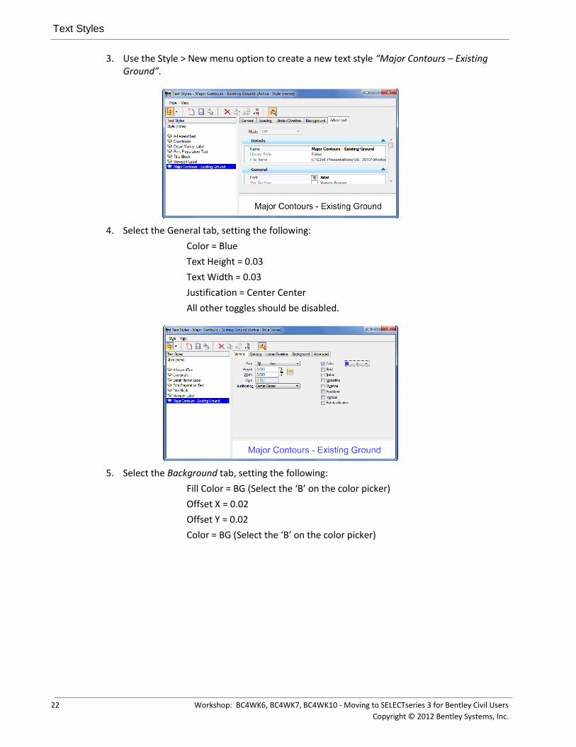
3. Use the Style > New menu option to create a new text style “Major Contours – Existing Ground”.
4. Select the General tab, setting the following:
Color = Blue
Text Height = 0.03
Text Width = 0.03
Justification = Center Center
All other toggles should be disabled.
5. Select the Background tab, setting the following:
Fill Color = BG (Select the ‘B’ on the color picker)
Offset X = 0.02
Offset Y = 0.02
Color = BG (Select the ‘B’ on the color picker)
Element Templates
Workshop: BC4WK6, BC4WK7, BC4WK10 - Moving to SELECTseries 3 for Bentley Civil Users 23
Copyright © 2012 Bentley Systems, Inc.
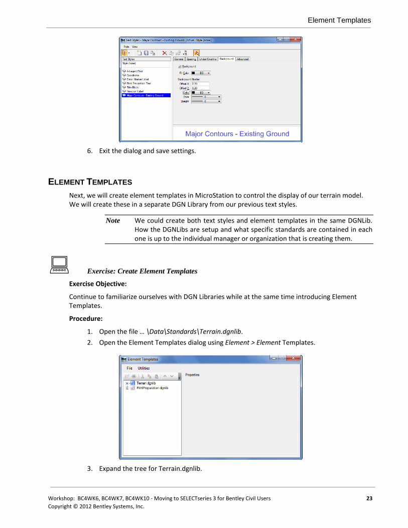
6. Exit the dialog and save settings.
ELEMENT TEMPLATES
Next, we will create element templates in MicroStation to control the display of our terrain model. We will create these in a separate DGN Library from our previous text styles.
Note We could create both text styles and element templates in the same DGNLib. How the DGNLibs are setup and what specific standards are contained in each one is up to the individual manager or organization that is creating them.
Exercise: Create Element Templates
Exercise Objective:
Continue to familiarize ourselves with DGN Libraries while at the same time introducing Element Templates.
Procedure:
1. Open the file … \Data\Standards\Terrain.dgnlib.
2. Open the Element Templates dialog using Element > Element Templates.
3. Expand the tree for Terrain.dgnlib.
Element Templates
24 Workshop: BC4WK6, BC4WK7, BC4WK10 - Moving to SELECTseries 3 for Bentley Civil Users
Copyright © 2012 Bentley Systems, Inc.
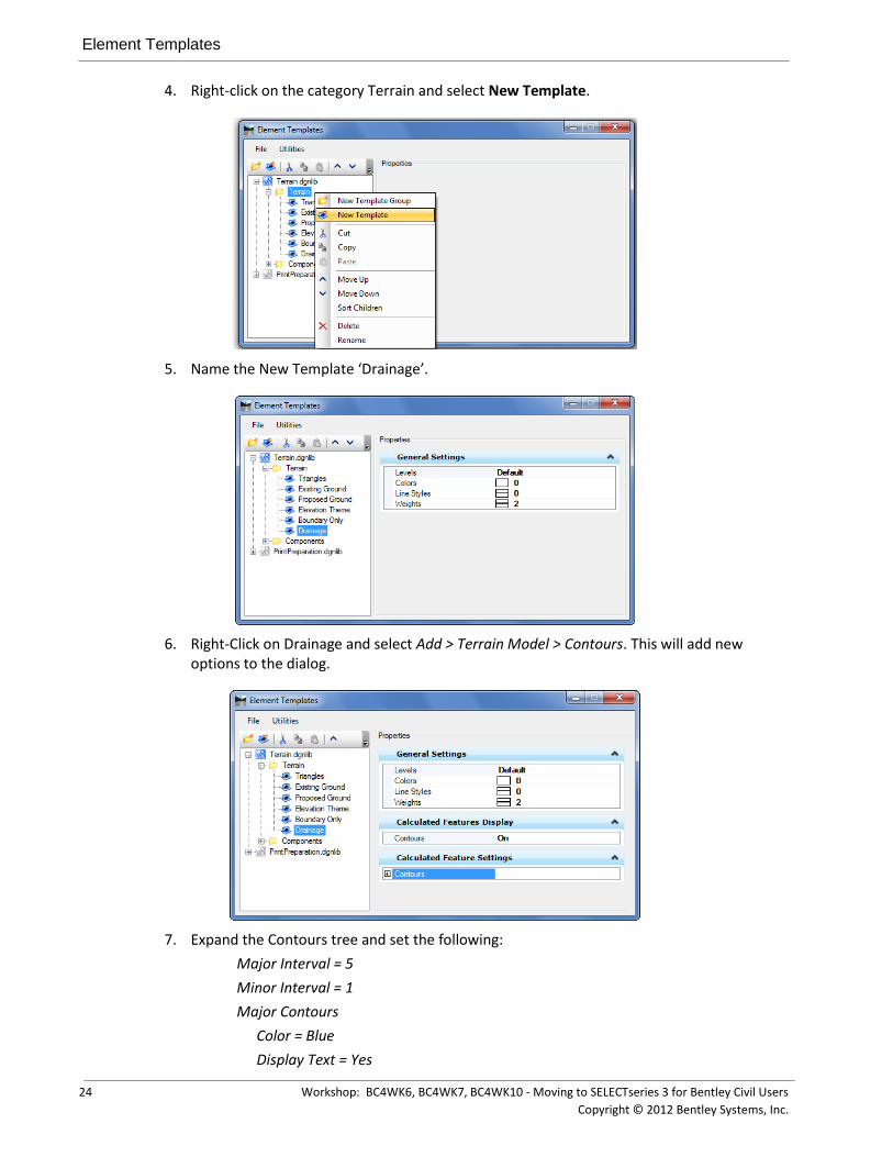
4. Right-click on the category Terrain and select New Template.
5. Name the New Template ‘Drainage’.
6. Right-Click on Drainage and select Add > Terrain Model > Contours. This will add new options to the dialog.
7. Expand the Contours tree and set the following:
Major Interval = 5
Minor Interval = 1
Major Contours
Color = Blue
Display Text = Yes

Using Standards
Workshop: BC4WK6, BC4WK7, BC4WK10 - Moving to SELECTseries 3 for Bentley Civil Users 25
Copyright © 2012 Bentley Systems, Inc.
Text Style = Major Contours – Existing Ground
Text Interval = 200
Minor Contours
Color = Red
Display Text = No
8. Repeat steps 3-5 to create a second element template named “Survey”.
9. Expand the Contours tree and set the following:
Major Interval = 10
Minor Interval = 2
Major Contours
Color = Green
Display Text = No
Minor Contours
Color = Orange
Display Text = No
10. Close the dialog.
USING STANDARDS
In our final exercise, we’ll use the standards that we’ve previously stored in our DGNLibs in order to control the display and labeling of a terrain model.
Exercise: Display Terrain Model
Exercise Objective:
Use previously created standards from DGNLibs to display and label a terrain model.
Terrain Model Tools Used:
TERRAIN MODELING PANEL ICON TOOL
Create From File
Procedure:
1. Open the file … \Data\ExistingGround.dgn.
The Terrain Model tools are located on the task navigation in group named “Terrain Modeling”.
2. Select the Create From File command.
3. Select the Ground.TIN file or the Ground.DTM file, whichever you prefer.
Note If selecting from a MX model.fil all the models contained will be listed in the tree view to pick and import.
4. Set the dialog settings as follows:
Source File Units = US Survey Feet
Chapter Summary
26 Workshop: BC4WK6, BC4WK7, BC4WK10 - Moving to SELECTseries 3 for Bentley Civil Users
Copyright © 2012 Bentley Systems, Inc.
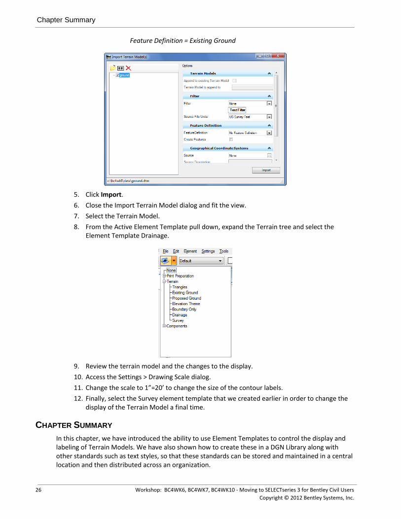
Feature Definition = Existing Ground
5. Click Import.
6. Close the Import Terrain Model dialog and fit the view.
7. Select the Terrain Model.
8. From the Active Element Template pull down, expand the Terrain tree and select the Element Template Drainage.
9. Review the terrain model and the changes to the display.
10. Access the Settings > Drawing Scale dialog.
11. Change the scale to 1”=20’ to change the size of the contour labels.
12. Finally, select the Survey element template that we created earlier in order to change the display of the Terrain Model a final time.
CHAPTER SUMMARY
In this chapter, we have introduced the ability to use Element Templates to control the display and labeling of Terrain Models. We have also shown how to create these in a DGN Library along with other standards such as text styles, so that these standards can be stored and maintained in a central location and then distributed across an organization.

Workshop: BC4WK6, BC4WK7, BC4WK10 - Moving to SELECTseries 3 for Bentley Civil Users 27
Copyright © 2012 Bentley Systems, Inc.
Chapter 4: Project Explorer
OVERVIEW
Project Explorer is a standard dialog with tree views for Links and Files for managing data in the current MicroStation project. The tabs for Links and Files will not be covered in this workshop and more information is available in MicroStation Help. This capability has been expanded to manage civil data by adding tabs for Survey, Civil Model and Civil Standards.
You will take a tour of the sections, settings and capabilities of the Civil Standards tab along with a brief review of the Civil Model tab. The Survey tab is most applicable when survey data is present and that is outside the scope of this workshop.
The Project Explorer is accessible from MicroStation > File > Project Explorer or from the Primary Tool Bar. There are settings to control which tabs are displayed and you will be using the dialog. If the Project Explorer is not visible on your Primary Toolbar then right-click on the toolbar and toggle on Project Explorer. This command can be docked on either the left of right side of the screen in a pinned or unpinned state. Please open the command and leave the dialog on the desktop undocked.
Exercise: Tour of Project Explorer
Exercise Objective: Familiarization with Project Explorer’s Civil Model and Civil Standards tabs.
Procedure:
Settings
1. Open the file … \data\standards\features.dgnlib.
The tabs that are visible can be configured in each design file. A possible use is to not show the Survey tab on seed files used by designers.
2. Open MicroStation > Settings > Project Explorer to view the options. At the top you see the various tabs set to true.
3. Change the Survey tab to false since we are not going to use it and then select OK. On the dismissal of the Settings the Project Explorer changes and the Survey tab is no longer visible.
Hint In dialogs which have True/False or On/Off instead of clicking on the drop down item and selecting the state you can change binary state items by double clicking on the name. Try it by double clicking on Survey to change states.
Civil Model
4. Select the Civil Model tab. This tab contains a breakdown of the civil data objects that exist in this design file and any referenced data.

Chapter Summary
28 Workshop: BC4WK6, BC4WK7, BC4WK10 - Moving to SELECTseries 3 for Bentley Civil Users
Copyright © 2012 Bentley Systems, Inc.
The first step in the hierarchy is design file. Any design files attached to this design file will also appear in the tree view. When present a plus (+) to the left of an item indicates additional information in the tree.
Under each design file is a listing of data types:
Linear Elements – featurized lines, curves, spirals, etc. Point Elements – featurized points 3D Linear Elements – featurized elements in 3D Terrain Models – lists the terrain models Corridors – lists the corridors and all dependent data Superelevation – lists superelevation data Civil Cells – lists civil cells present in the design file Civil Objects – lists the civil objects present in the design file
Each type has a further break down of information which we will not go into today. Suffice it to say the data listing is extensive. Each item has a selection of actions available by right-clicking ranging from commands to properties that are appropriate actions for that data type.
Civil Standards
5. The Civil Standards tab provides access to features and settings stored in DGNLIB or design files.
The top level has the current design file and Libraries. Libraries are the collection of DGNLIB files that are associated with the MicroStation project. As settings and standards are used they are copied into the design file.
Under the Design File and Libraries are the following sections:
Civil Cells – a collection that can be placed as a whole Design Standards – include curve tables for horizontal and vertical curves by speed Feature Management – holds the collection of features Filters – contains filters and filter groups for import from graphics Project Settings – contain Corridor and Survey settings Roundabouts – contains the list of roundabouts available for placement
Feature Management population and uses are covered in Chapters 5 and 6 of this workshop.
Design Standards are covered in Chapter 8 of this workshop.
CHAPTER SUMMARY
The Civil Standards tab provides access to setting, features and design standards. The Civil Model tab has the civil data in a hierarchical tree structure. Pertinent actions can be invoked with the right-click menus on each entry.

Workshop: BC4WK6, BC4WK7, BC4WK10 - Moving to SELECTseries 3 for Bentley Civil Users 29
Copyright © 2012 Bentley Systems, Inc.
Chapter 5: Linking Legacy Settings
OVERVIEW
Bentley Civil products, GEOPAK, InRoads and MX each have files that define names of styles and how they are drawn in graphics. These files represent an investment in time and effort so the transfer of these styles to features in the DGNLIB is important. Specifically we are not importing the styles. The files are linked to features of the same name in the DGNLIB. These features are looking up symbology out of a .DDB, .PSS or .XIN file and placing graphics with those values.
Exercise: Link Active Styles
You will link the product files of your choosing, review the properties and learn what changes are necessary to get the appropriate graphics. You will do this for both survey and design entries.
Exercise Objective:
Link the active styles from the product of your choice.
Getting Started
GEOPAK: Set the filter to .DDB and select the file from the data directory.
InRoads: Set the filter to .XIN and select the file from the data directory.
MX: Set the filter to .PSS and select the file MXRoad.pss from the data directory.
Procedure
1. Open or continue to use the file … \data\standards\features.dgnlib.
2. Open the Project Explorer and the Civil Standards tab.
3. Click on the Feature Management +. There should be nothing under the entry.
4. Right-click on Feature Management and select Link Active Feature Styles. Note if you are using GEOPAK, Use Item Name option.
InRoads options GEOPAK options MX options
Upon selection the styles are read into the DGNLIB file as linear, point and surface features.
Overview
30 Workshop: BC4WK6, BC4WK7, BC4WK10 - Moving to SELECTseries 3 for Bentley Civil Users
Copyright © 2012 Bentley Systems, Inc.
WHAT HAPPENED - INROADS?
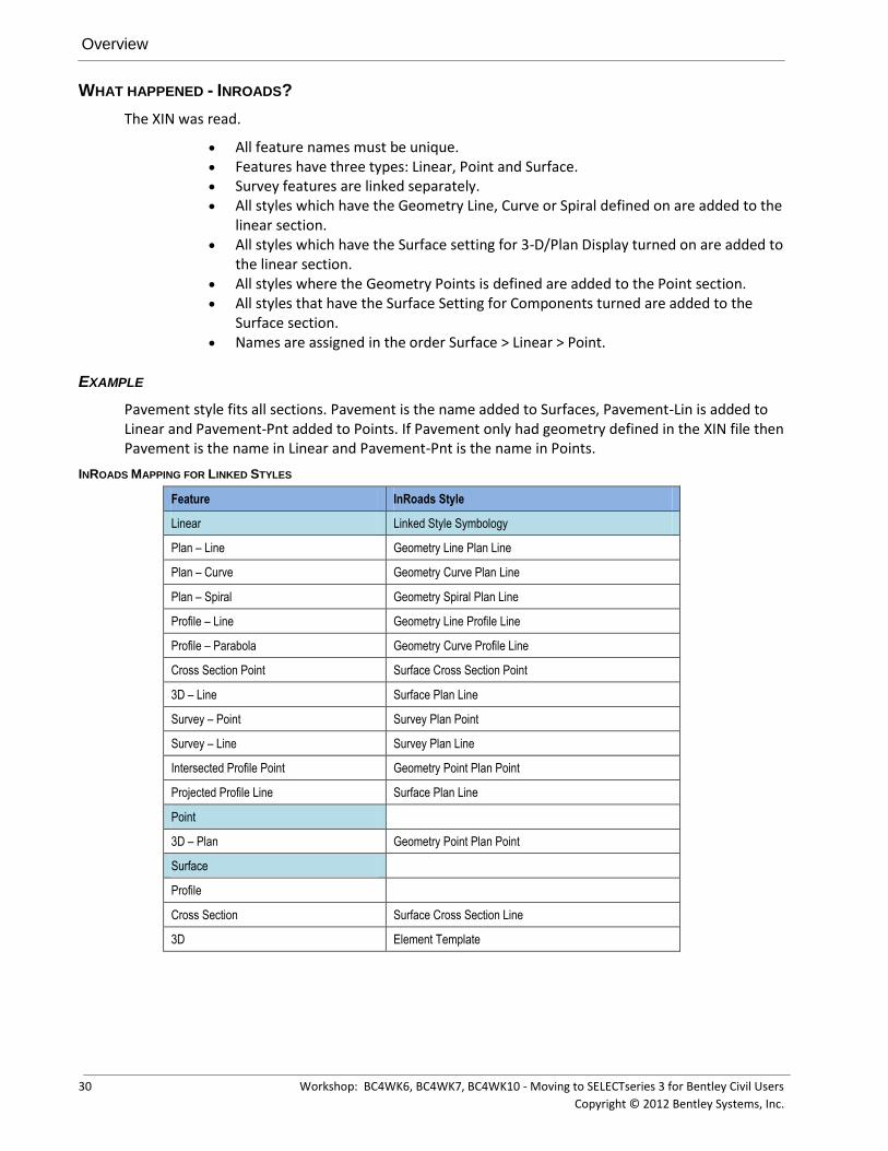
The XIN was read.
All feature names must be unique. Features have three types: Linear, Point and Surface. Survey features are linked separately. All styles which have the Geometry Line, Curve or Spiral defined on are added to the
linear section. All styles which have the Surface setting for 3-D/Plan Display turned on are added to
the linear section. All styles where the Geometry Points is defined are added to the Point section. All styles that have the Surface Setting for Components turned are added to the
Surface section. Names are assigned in the order Surface > Linear > Point.
EXAMPLE
Pavement style fits all sections. Pavement is the name added to Surfaces, Pavement-Lin is added to Linear and Pavement-Pnt added to Points. If Pavement only had geometry defined in the XIN file then Pavement is the name in Linear and Pavement-Pnt is the name in Points.
INROADS MAPPING FOR LINKED STYLES
Feature InRoads Style
Linear Linked Style Symbology
Plan – Line Geometry Line Plan Line
Plan – Curve Geometry Curve Plan Line
Plan – Spiral Geometry Spiral Plan Line
Profile – Line Geometry Line Profile Line
Profile – Parabola Geometry Curve Profile Line
Cross Section Point Surface Cross Section Point
3D – Line Surface Plan Line
Survey – Point Survey Plan Point
Survey – Line Survey Plan Line
Intersected Profile Point Geometry Point Plan Point
Projected Profile Line Surface Plan Line
Point
3D – Plan Geometry Point Plan Point
Surface
Profile
Cross Section Surface Cross Section Line
3D Element Template

Overview
Workshop: BC4WK6, BC4WK7, BC4WK10 - Moving to SELECTseries 3 for Bentley Civil Users 31
Copyright © 2012 Bentley Systems, Inc.
HOW THE LINKING WORKS
A native style is linked to a particular attribute such as Plan or 3D.
WHAT HAPPENED - GEOPAK?
The DDB was read.
All feature names must be unique. Features have three types: Linear, Point and Surface. Survey features are linked separately to the Survey Manager Database (SMD) in XML
format. Features may be linked to DDB Item Names or Item Descriptions. The Item
Descriptions link is useful if the Item Name is simply a pay item number with no description.

Overview
32 Workshop: BC4WK6, BC4WK7, BC4WK10 - Moving to SELECTseries 3 for Bentley Civil Users
Copyright © 2012 Bentley Systems, Inc.
Native Style in Project Manager Used in Plan and Several Profile Options
Native Style Relating to DD Item Name and Associated Settings
WHAT HAPPENED? - MX
The PSS was read into a flat structure the same as we get in Style Set Editor.
Since a MX PSS only holds a single style representation and does not distinguish between plan / profile / section / 3d, by default the same style definition is applied to each persona. The persona styles can be modified later to take advantage of different display representations.
The MX string feature types are matched to the appropriate feature definitions from the following table:
Feature Supported MX String types Default Style Mapping
Surface Cross Section strings
Long Section Strings
Triangulation Strings
MicroStation Element Template
On import a new Element Template is created
- Category ( PSS name) > Feature Name
Using feature style to define Level, colour, linestyle, weight, material (if defined).
Linear Feature Strings
Interface Strings
Master Strings
Geometry Strings
PSS feature
Point Survey Station
Point
Cadastre
PSS feature
Feature names must be unique and names are assigned in the order Surface > Linear > Point.

Linking Survey Styles
Workshop: BC4WK6, BC4WK7, BC4WK10 - Moving to SELECTseries 3 for Bentley Civil Users 33
Copyright © 2012 Bentley Systems, Inc.
The PSS structure is ‘flat’ and so all features are initially loaded to match this historic flat feature definition structure. However this is an opportunity to categorize features into groups, possibly of similar features or into a method of your own choosing, too enhance the normal MX feature structure.
Example the MXRoad.pss could be imported and grouped with sub categories for all the different string features that fit the category like Carriageways / Shoulders / Alignments / Earthworks etc.
In this case, create a category called MXRoad and move all features under it.
LINKING SURVEY STYLES
Note the linking in the previous section did not include Survey. They are linked separately.
Link Survey Styles to DGNLib
Objective:
Now we will link the Survey styles to this DGNLIB.
Procedure:
The steps vary because the linked file is identified from disk as opposed to the loaded .XIN file.
1. Continue in …\data\standards\start_features.dglib.
2. Right-click menu on Feature Management and select Link Survey Feature Definitions from the pop-up menu.
This dialog allows you to select the three style files for GEOPAK, InRoads and MX.
InRoads: Select the … \data\standards\civil.xin and then select Open to process this file into the DGNLIB file.

Chapter Summary
34 Workshop: BC4WK6, BC4WK7, BC4WK10 - Moving to SELECTseries 3 for Bentley Civil Users
Copyright © 2012 Bentley Systems, Inc.
GEOPAK: Select … \data\standards\civil.xin smd.xml (SMD file in xml format) and then select Open to process this file into the DGNLIB file.
MX: Create a new Category Simple Survey and Select the … \data\standards\Simple Survey.pss.
Note The survey features are created if they did not exist in the previously imported files. If the feature does exist then the survey information is added to the existing feature.
Figure 1 Survey Defined Figure 2 No Survey Defined
CHAPTER SUMMARY
These steps are how style files are linked to features in a DGNLIB. You did not transfer the symbology into the DGNLIB. You have created entries that are linked back to the DDB/PSS/XIN file where the native product symbology is defined or to element templates in a DGNLIB.

Workshop: BC4WK6, BC4WK7, BC4WK10 - Moving to SELECTseries 3 for Bentley Civil Users 35
Copyright © 2012 Bentley Systems, Inc.
Chapter 6: Working With Features
OVERVIEW
The Project Explorer has facilities to create, maintain and delete the features you linked in the previous chapter. These capabilities will be worked with in this chapter. You will explore these functions that can be used by System Administrators or Project Managers setting up the Civil Standards for your organization. These steps are similar whether you are in GEOPAK, InRoads or MX.
MANAGING FEATURES
You will create, edit, rename, move, categorize and delete linear, point and surface features in this chapter.
Working with Features
Exercise Objective:
Review and modify features of Prop_Horiz Alignment.
Command used: Project Explorer
Procedure:
1. Continue in …\data\standards\features.dgnlib.
2. Select the Prop_Horiz Alignment feature, open menu and review properties.
We’ll edit some of the properties to make the feature even more useful.
3. Starting out, default naming for the feature can be defined. Here the example is set to PCL1 which would be the name of the first element with this feature in the design. The second element would be named PCL2.
4. Next take a look at the Plan Settings.
Besides the Native Style which is set automatically, there are settings to export the geometry to the ALG/GPK/FIL files or not and whether or not to annotate the geometry according to the style. Set Auto Annotate to True and whenever any element is placed with this feature will have the annotation placed.
Managing Features
36 Workshop: BC4WK6, BC4WK7, BC4WK10 - Moving to SELECTseries 3 for Bentley Civil Users
Copyright © 2012 Bentley Systems, Inc.
5. Set Auto Annotate to True.
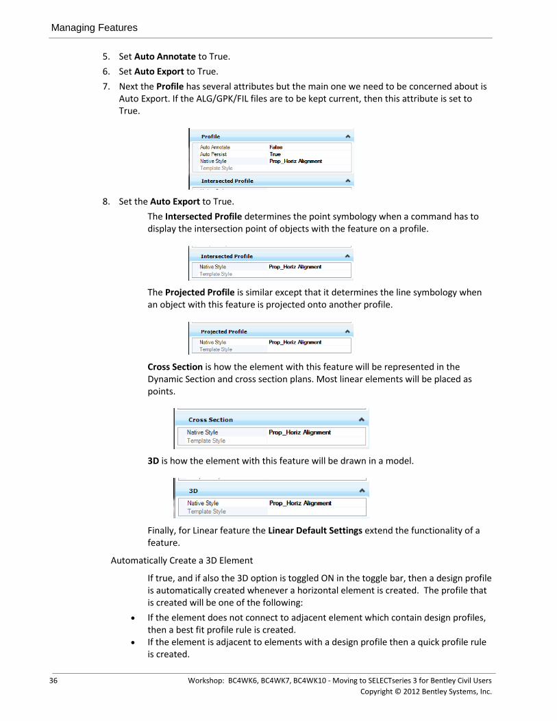
6. Set Auto Export to True.
7. Next the Profile has several attributes but the main one we need to be concerned about is Auto Export. If the ALG/GPK/FIL files are to be kept current, then this attribute is set to True.
8. Set the Auto Export to True.
The Intersected Profile determines the point symbology when a command has to display the intersection point of objects with the feature on a profile.
The Projected Profile is similar except that it determines the line symbology when an object with this feature is projected onto another profile.
Cross Section is how the element with this feature will be represented in the Dynamic Section and cross section plans. Most linear elements will be placed as points.
3D is how the element with this feature will be drawn in a model.
Finally, for Linear feature the Linear Default Settings extend the functionality of a feature.
Automatically Create a 3D Element
If true, and if also the 3D option is toggled ON in the toggle bar, then a design profile is automatically created whenever a horizontal element is created. The profile that is created will be one of the following:
If the element does not connect to adjacent element which contain design profiles, then a best fit profile rule is created.
If the element is adjacent to elements with a design profile then a quick profile rule is created.

Managing Features
Workshop: BC4WK6, BC4WK7, BC4WK10 - Moving to SELECTseries 3 for Bentley Civil Users 37
Copyright © 2012 Bentley Systems, Inc.
In both cases, if the adjacent elements do not contain a design profile, the rule is still created but the 3D element will not appear until the adjacent elements receive a design profile.
Example: Line BY points which stands alone, with Create 3D toggled on. A best fit profile rule is created. If per chance no active terrain is present then the rule is still created but will not be evident until an active profile is named.
Example: Use Arc Between Elements to create a curb return. A quick profile for the curb return is created based on the design profiles of the adjacent edges of pavement. If, per chance, the adjacent edges do not yet have a design profile then the rule is still created but no profile nor 3D will be evident until such time as both adjacent elements receive a design profile definition.
Template: Defines a template which will automatically be attached to the H geometry element as soon as it is placed. You must have the template toggle ON in the Features Toggle bar. Similar to above, no 3D model will appear until the element has a design profile created, so using the Template toggle will often go hand in hand with Create 3D toggle. But, you can toggle ON template even without a design profile and the template drop will be created but no 3D model until such time as a design profile is named.
Terrain Model Feature – when the 3D element is created using this feature definition, define what sort of behavior it will have when it is used in a terrain model (break line, boundary, etc.)
Create Template Geometry – if you create a template drop and if the template contains points matching this feature definition then create horizontal offset transition elements in plan. Example: EOP and sidewalk lines.
9. Right-click on the Linear Category and create a new feature then rename it to Roadway from New.
10. Set Automatically Create 3D Element to True.
11. Set the Template to “2 Lane Rural” from the attached template library
12. Terrain Model Feature Type to None
13. Create Template Geometry to True
Point Features
This section contains features linked to styles that had geometry points defined.
Surface Features
The surface features are used to define terrain model attributes, surface meshes and component displays.
14. First, in the Project Explorer > Civil Standards > Feature Management > Civil.xin - Expand the Surfaces category. These are the names of the InRoads Styles that were defined as components.

Managing Features
38 Workshop: BC4WK6, BC4WK7, BC4WK10 - Moving to SELECTseries 3 for Bentley Civil Users
Copyright © 2012 Bentley Systems, Inc.
15. Now open the properties for Aggregate by right-clicking on the name and selecting Properties.
16. Set the element template for Cross Section and 3D to Components Aggregate using the tree view of the Element Templates that is shown.

Managing Features
Workshop: BC4WK6, BC4WK7, BC4WK10 - Moving to SELECTseries 3 for Bentley Civil Users 39
Copyright © 2012 Bentley Systems, Inc.
17. Verify that the Surface Feature Properties look as they do in the following example.
18. Perform the same steps for the rest of the surface features.
Next you will copy a feature to make a mesh feature for Design Corridors.
19. Right-Click on Surfaces, Aggregate and select Copy

Managing Features
40 Workshop: BC4WK6, BC4WK7, BC4WK10 - Moving to SELECTseries 3 for Bentley Civil Users
Copyright © 2012 Bentley Systems, Inc.
20. Right-click on Surfaces and select Paste
21. Now rename the copied feature from Aggregate1 to Design Mesh. This entry would be used to symbolize 3D meshes created by corridors. Change the Properties for 3D to Design\Mesh
The next part of the exercise is to create a new terrain model feature from the element template you defined earlier.

Managing Features
Workshop: BC4WK6, BC4WK7, BC4WK10 - Moving to SELECTseries 3 for Bentley Civil Users 41
Copyright © 2012 Bentley Systems, Inc.
22. Right-click on Surface again and select the New Feature Definition > Surface Feature.
23. Rename the feature from New to Existing. The name by default is active for changing it to a new feature name.
24. Open the properties for Existing and set the 3D to the Existing\DTM element template.
25. The Cross Section should be set to the Native Style called Existing Ground as well as the Profile.
26. Finally, set the Volume Option to Existing. This is very important when running cross section average end area volumes because without this defined there is no existing surface defined.

Chapter Summary
42 Workshop: BC4WK6, BC4WK7, BC4WK10 - Moving to SELECTseries 3 for Bentley Civil Users
Copyright © 2012 Bentley Systems, Inc.
27. This concludes the exercise.
CHAPTER SUMMARY
In this chapter you created, copied, renamed and modified attributes of different types of features. The attributes in each feature define how the elements are shown in various stages of the drawing/models.

Workshop: BC4WK6, BC4WK7, BC4WK10 - Moving to SELECTseries 3 for Bentley Civil Users 43
Copyright © 2012 Bentley Systems, Inc.
Chapter 7: Seed Files
OVERVIEW
Seed files have always been an important part of a MicroStation configuration. The beauty of the seed file is that it can be used to standardize drawings as every new file that you create will have the same attributes (e.g. global origin, color table, cell library attachments, working units, views, etc.) as those that are in the seed file. In Bentley Civil V8i SELECTseries 3, there are certain civil settings and attributes that you will want to consider setting in your design file.
PROJECT DESCRIPTION
In this exercise, we’ll review the specific settings that can be very useful on civil projects, as well as the ability to set or standardize these settings within a seed file in order to propagate these standards to new drawings.
GEOGRAPHIC COORDINATE SYSTEMS
MicroStation V8i introduced the ability to assign Geographic Coordinate Systems (GCS) to design file models. This functionality allows the user to specify the position of the design contents on the earth´s surface. Once that position is established, the design can then be easily coordinated with other data for which the geographic location is also known. With civil operations, this can be very useful since civil applications can make use of this GCS when importing data in order to ascertain the location of the imported data and perform a re-projection if required.
Exercise: Assign Geographic Coordinate System
In this first section, we’ll review what a Geographic Coordinate System is and then assign one to our seed file model.
Exercise Objective:
Familiarize ourselves with Geographic Coordinate Systems and the ability to assign them to a design file model.
Procedure:
1. Open … \data \Seed3D.dgn.
Geographic Coordinate Systems
44 Workshop: BC4WK6, BC4WK7, BC4WK10 - Moving to SELECTseries 3 for Bentley Civil Users
Copyright © 2012 Bentley Systems, Inc.
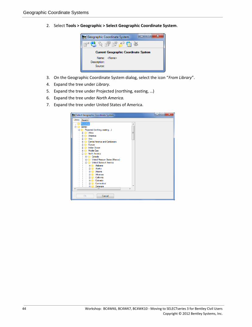
2. Select Tools > Geographic > Select Geographic Coordinate System.
3. On the Geographic Coordinate System dialog, select the icon “From Library”.
4. Expand the tree under Library.
5. Expand the tree under Projected (northing, easting, …)
6. Expand the tree under North America.
7. Expand the tree under United States of America.

Annotation Scale
Workshop: BC4WK6, BC4WK7, BC4WK10 - Moving to SELECTseries 3 for Bentley Civil Users 45
Copyright © 2012 Bentley Systems, Inc.
8. Finally, expand the tree under Tennessee and select the GCS as shown.
9. Click OK to accept. The GCS has now been assigned to the design file model.
10. Close the Geographic Coordinate System dialog.
ANNOTATION SCALE
Annotation Scale allows a user to set the default scale factor within a particular design file model. This scale is then applied to any text, line styles and cells (if the cells are enabled to recognize the annotation scale) that are drawn in the model.
Next, we’ll review Annotation Scales and assign a default value to our seed file model.
Exercise: Assign Annotation Scale
Exercise Objective:
Familiarize ourselves with Annotation Scales and the ability to assign them to a design file model.
Procedure:
1. Remain in the file C:\BC4WK6_7_10 - Moving to SS3 for Bentley Civil Users\data \Seed3D.dgn.
Civil Formatting Options
46 Workshop: BC4WK6, BC4WK7, BC4WK10 - Moving to SELECTseries 3 for Bentley Civil Users
Copyright © 2012 Bentley Systems, Inc.
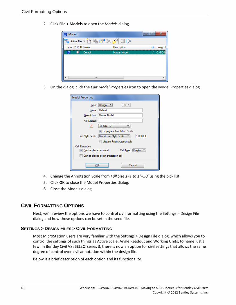
2. Click File > Models to open the Models dialog.
3. On the dialog, click the Edit Model Properties icon to open the Model Properties dialog.
4. Change the Annotation Scale from Full Size 1=1 to 1”=50’ using the pick list.
5. Click OK to close the Model Properties dialog.
6. Close the Models dialog.
CIVIL FORMATTING OPTIONS
Next, we’ll review the options we have to control civil formatting using the Settings > Design File dialog and how those options can be set in the seed file.
SETTINGS > DESIGN FILES > CIVIL FORMATTING
Most MicroStation users are very familiar with the Settings > Design File dialog, which allows you to control the settings of such things as Active Scale, Angle Readout and Working Units, to name just a few. In Bentley Civil V8i SELECTseries 3, there is now an option for civil settings that allows the same degree of control over civil annotation within the design file.
Below is a brief description of each option and its functionality.

Civil Formatting Options
Workshop: BC4WK6, BC4WK7, BC4WK10 - Moving to SELECTseries 3 for Bentley Civil Users 47
Copyright © 2012 Bentley Systems, Inc.
EXPORT TO NATIVE
“Export to Native” is a functionality within Bentley Civil V8i SELECTseries 3 that allows the user to keep a version of the native geometry database (.GPK, .ALG, .FIL) in synch with civil geometry stored within the design file. For example, when enabled the user can store an alignment in the design file and that alignment will be automatically stored in the native geometry database as well. Delete that alignment from the design file, and that alignment will be deleted from the native geometry database. This “Export to Native” functionality is feature based in that the option to “Export to native” must be set to “true” or “false” for each particular feature.
This option in the Design File Settings dialog controls whether Civil Geometry is exported to the native database automatically or not. When set to “Use Feature Setting”, then any civil geometry elements will be exported to the native database when stored with a feature that has the Export to Native option set to “true”. When set to Manual, Civil Geometry elements can only be exported to the native database via a manual export, regardless of whether the feature being used allows for it or not.
COORDINATE SETTINGS
This option allows the user to control the display and precision of their coordinates within any of the civil dialogs. In addition, this setting also controls how any inputted coordinates will be interpreted. For example, if set to “X, Y” then all coordinates will be interpreted and displayed as being in the “X, Y” format. If set to “Nothing, Easting” then the same would apply.
RATIO SETTINGS (DISTANCE: OFFSET)
This option allows the user to control the display and precision of their ratios within any of the civil dialogs. In addition, this setting also controls how any inputted ratios will be interpreted. For example, if set to “1:D” then all ratios will be interpreted and displayed in this format (e.g. 1:100, 1:50, etc.). If set to “D:1” then the ratios would be similarly displayed and interpreted (e.g. 5:1, 10:1, etc.).
STATION SETTINGS
Here, the user can control the format, delimiter and precision of the station values to be used and displayed in the civil dialogs. In addition, there are two options to control how equations are represented within the station values.

Civil Formatting Options
48 Workshop: BC4WK6, BC4WK7, BC4WK10 - Moving to SELECTseries 3 for Bentley Civil Users
Copyright © 2012 Bentley Systems, Inc.
By Name – This is the standards InRoads presentation (A100+00, B105+00, etc.).
By Index – This is the standard GEOPAK presentation (100+00 R 1, 105+00 R 2, etc.).
RADIUS SETTINGS
Degrees of Curve Method – Two options are available, Arc and Chord.
Degree of Curve Length – This sets the standard definition of a 1^ curve.
Radius Toggle Char – This allows the user to specify which character will be used within the civil dialogs to ‘toggle’ between a radius definition and a degree of curve definition.
PROFILE SETTINGS
This option allows the user to control the precision and display/input formats of slopes and ratios within a profile context. In addition, the default Vertical Curve Parameter Format (Radius, K Value or M Value) can be set as well.

Civil Formatting Options
Workshop: BC4WK6, BC4WK7, BC4WK10 - Moving to SELECTseries 3 for Bentley Civil Users 49
Copyright © 2012 Bentley Systems, Inc.
Exercise: Review and Modify Civil Formatting Options
Exercise Objective:
Familiarize ourselves with the new Civil Formatting option available under the Settings > Design file dialog and the ability to assign these settings in a seed design file.
Procedure:
1. Remain in the file C:\BC4WK6_7_10 - Moving to SS3 for Bentley Civil Users\data \Seed3D.dgn.
2. Open the Settings > Design File dialog and click on the Civil Formatting option.
3. Modify the following options in our seed file model:
Coordinate Settings > Precision: 0.12
Ratio Settings > Precision: 0.12
Station Settings > Precision: 0.12
Degree of Curve Length: 100
Profile Settings
Elevation Precision: 0.12
Slope Format: Decimal
Slope Precision: 0.12
Ratio Precision: 0.12
Vertical Curve Parameter Format: KValue
4. Click OK to close the Design File Settings dialog.
WORKSPACE > PREFERENCES > CIVIL FORMATTING
Finally, we’ll review the options we have to control civil formatting under the Workspace > Preferences dialog and how those options can be set in the seed file.

Civil Formatting Options
50 Workshop: BC4WK6, BC4WK7, BC4WK10 - Moving to SELECTseries 3 for Bentley Civil Users
Copyright © 2012 Bentley Systems, Inc.
Whereas the MicroStation Design File Settings allow for the configuring of standards within a design file that can be propagated throughout an organization, the Workspace Preferences are more geared toward the individual user. In other words, they allow each user to control settings such as the look and feel of MicroStation – things that a user may prefer but don’t have an overall effect on the project data.
In the same vein, civil formatting options have been added to Workspace Preferences in Bentley Civil V8i SELECTseries 3. These are option that have no overall effect on the generated design data, but are geared more toward the look and feel of civil on a user level.
Although geared more toward individual users, an organization may want to set some of these as default values in their seed files.
MANIPULATOR SETTINGS
These settings allow the user to control the settings and symbology of the civil geometry manipulators and any associated text.
SURVEY LOCATOR
This setting is used by the Survey tools to control the display and symbology of the locator.

Civil Formatting Options
Workshop: BC4WK6, BC4WK7, BC4WK10 - Moving to SELECTseries 3 for Bentley Civil Users 51
Copyright © 2012 Bentley Systems, Inc.
SUPERELEVATION SETTINGS
When the super elevation components are drawn into the design file, these two options allow the user to specify whether they are to be draw as Color Shaded Fill or Boundary Only.
MAXIMUM ERROR ELLIPSE
Survey only – This setting allows the user to specify a major error ellipse value with regard to the standard deviation resulting from a Least Squares Adjustment. Any standard deviation exceeding this limit would result in a graphical flag based on this symbology.
MEDIUM ERROR ELLIPSE
Survey only – This setting allows the user to specify a medium error ellipse value with regard to the standard deviation resulting from a Least Squares Adjustment. Any standard deviation exceeding this limit would result in a graphical flag based on this symbology.
MINIMUM ERROR ELLIPSE
Survey only – This setting allows the user to specify a minimum error ellipse value with regard to the standard deviation resulting from a Least Squares Adjustment. Any standard deviation exceeding this limit would result in a graphical flag based on this symbology.

Chapter Summary
52 Workshop: BC4WK6, BC4WK7, BC4WK10 - Moving to SELECTseries 3 for Bentley Civil Users
Copyright © 2012 Bentley Systems, Inc.
Exercise: Review and Modify the Preferences > Civil Formatting Options
Exercise Objective:
Familiarize ourselves with the new Civil Formatting options available under the Workspace > Preferences dialog and the ability to assign these settings in a seed design file.
Procedure:
1. Remain in the file … \data \Seed3D.dgn.
2. Open the Workspace > Preferences dialog.
3. Select View Options – Civil.
4. Make the following changes:
Manipulator Settings:
Manipulator Size: 25
Normal Color: Your choice of any color
5. Click OK to close the Preferences dialog.
CHAPTER SUMMARY
In this chapter, we have reviewed the various settings and how to set up seed files.

Workshop: BC4WK6, BC4WK7, BC4WK10 - Moving to SELECTseries 3 for Bentley Civil Users 53
Copyright © 2012 Bentley Systems, Inc.
Chapter 8: Standards
OVERVIEW
Two major applications within Bentley Civil SELECTseries3 require enterprise-wide set-up. These applications are:
Design standards – used by planning, design, and geometric review functions Superelevation preferences – used by design functions
Both applications can be based off AASHTO standards, but that is not required. Generally, state transportation agencies will use AASHTO as a starting point, compare to their own standards, and adjust accordingly.
Both applications are optional in usage. Therefore, they can be deployed at any time, within a total deployment or separately, as individual applications. However, the superelevation application needs to be implemented at the same time as Corridor Modeling.
DESIGN STANDARDS
Design standards can be used to maintain required curvature and other alignment checks when performing horizontal and vertical geometric layouts. They work at two levels:
Provide values for the element creation tools (for example, minimum radius and transition lengths)
Check the suitability of complex elements (for example, check for kinks in the alignment)
When a design standard is violated, feedback is provided in two ways:
An icon in the graphics, on the element that has the problem. Hover over the icon to reveal a tool tip report of the error
In the Civil Message Center
Design standards are normally utilized by Design personnel, and perhaps to a lesser extent, Planning and Preliminary Design staff.
In order to utilize Design standards, it is critical for each organization to review their standards in comparison to the AASHTO standards, and adjust accordingly. As standards rarely change, posting in a central location or ProjectWise in a read-only mode is recommended. As a designer uses a particular standard, it is automatically copied into their active design file, where it can be overruled on a file by file basis.
If your organization is already using SELECTseries 2, you need only add the vertical standards and associate them back to the horizontal standards. If you are not using SELECTseries 2, then you will define the vertical standards first, and then the horizontal.
Depending in the composition of your support staff, you may to enlist the expertise of your Standards engineer or Manager, along with key users within your Design section. They will be critical to define, review, and test standards prior to implementation.

Design Standards
54 Workshop: BC4WK6, BC4WK7, BC4WK10 - Moving to SELECTseries 3 for Bentley Civil Users
Copyright © 2012 Bentley Systems, Inc.
Multiple sets of standards can be defined within a DGNLib or one set per DGNLib. In order to create or modify the standards, you must be in the DGNLib where the data resides. The modification is done from within Project Explorer in the Civil Standards tab.
The data is based on design speed and a lot of the associated data is redundant. Therefore, you will want to think about the hierarchy that you want, so you utilize copy and paste functions.
Group Exercise: Review Design Standards
Objective:
In this exercise we are going to quickly review the common hierarchy of AASHTO standards.
Tools Used:
Project Manager
Procedure:
1. Open …\data\standards\AASHTO 2004 Design Standards.dgnlib.
2. Open Project Explorer.
3. Select the Civil Standards tab.
4. Select Design Standards.
5. Select Horizontal and navigate downwards to see the entire tree.
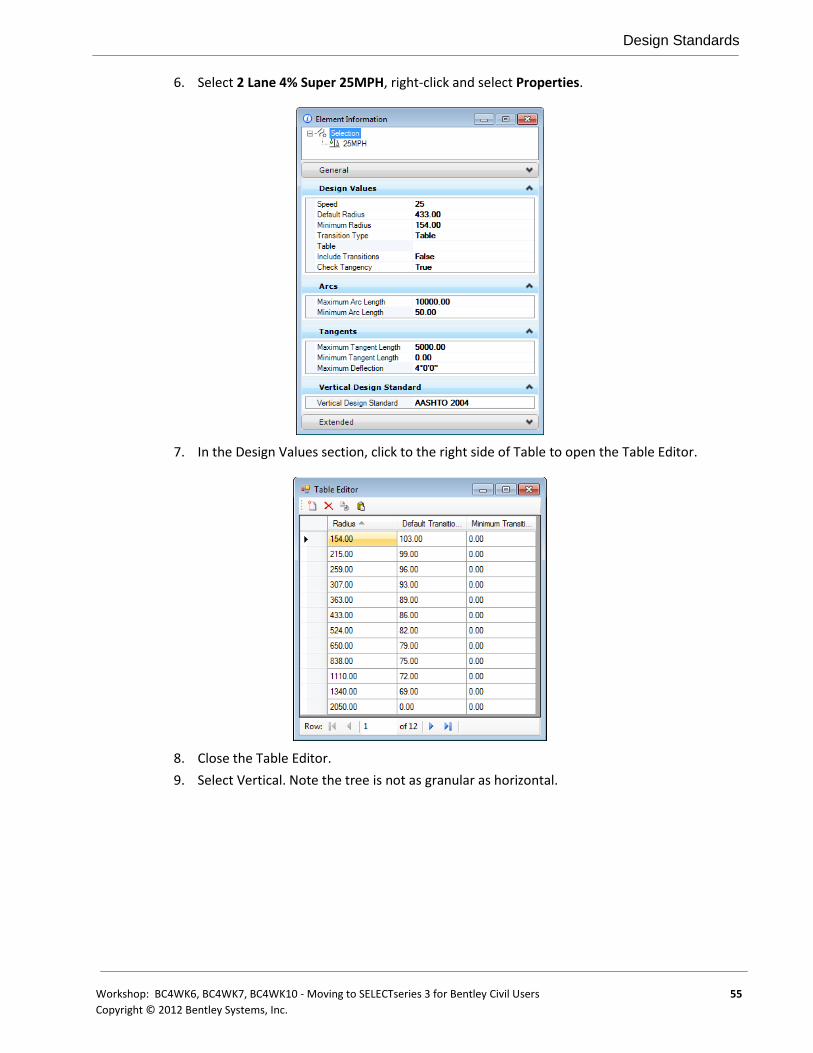
Design Standards
Workshop: BC4WK6, BC4WK7, BC4WK10 - Moving to SELECTseries 3 for Bentley Civil Users 55
Copyright © 2012 Bentley Systems, Inc.
6. Select 2 Lane 4% Super 25MPH, right-click and select Properties.
7. In the Design Values section, click to the right side of Table to open the Table Editor.
8. Close the Table Editor.
9. Select Vertical. Note the tree is not as granular as horizontal.

Design Standards
56 Workshop: BC4WK6, BC4WK7, BC4WK10 - Moving to SELECTseries 3 for Bentley Civil Users
Copyright © 2012 Bentley Systems, Inc.
10. Select AASHTO 2004 – 25MPH. Right-click and select Properties.
11. Click in the Table field to open the table.
Create a New Vertical Standard
Objective:
In this exercise we are going to copy an existing standard, then modify for our new standard. Within the Vertical standard, note that there is a gap for 30MPH.
Procedure:
1. Continue in …\data\standards\AASHTO 2004 Design Standards.dgnlib.

Design Standards
Workshop: BC4WK6, BC4WK7, BC4WK10 - Moving to SELECTseries 3 for Bentley Civil Users 57
Copyright © 2012 Bentley Systems, Inc.
2. Copy 25MPH and paste into AASHTO 2004. You’ll now have two entries: 25MPH and 25MPH1.
3. Right-click on 25MPH1, and select Rename. Change from 25MPH1 to 30MPH.
4. Right-click on 30MPH and select Properties.
5. Open the Table editor.
6. Add a blank line to the table by selecting New Item.
7. Add 30MPH with the following values:
FIELD VALUE
Sag Minimum 37
Sag Default 37
Crest Minimum 19
Crest Default 29
8. Close the table and Element Info and return to the Project Explorer.
Create a New Horizontal Standard
Objective:
In this exercise we are going to copy an existing standard, then modify for our new standard. Within the Vertical standard, note that there is a gap for 30MPH.
Procedure:
1. Continue in … data\standards\AASHTO 2004 Design Standards.dgnlib.
2. Copy the 4% 4 lane 30MPH to the 4% 2 lane grouping.
3. Normally, we would adjust the table, however, for the sake of expediency, we will skip this step.

Superelevation Preferences
58 Workshop: BC4WK6, BC4WK7, BC4WK10 - Moving to SELECTseries 3 for Bentley Civil Users
Copyright © 2012 Bentley Systems, Inc.
4. At the bottom of the Horizontal dialog, select 30MPH from the Vertical Standard Design List.
5. Close the DGNLib.
Verify the Results of the New Standards
Objective:
In this exercise we are going to verify that we created the 30MPH standard and how it’s utilized within horizontal and vertical geometry.
Procedure:
1. Open ..\data\geometry.dgn.
2. Open the Project Explorer and dock on the right side.
3. Open the Civil Message Center and dock on the bottom.
4. Select the Design Standards toolbar and stretch so you can see both entries in their entirety.
5. Select the Horizontal 2 Lane \ 4% Super \30MPH you just created. The Vertical should automatically display 30MPH since we associated them.
6. Select the Set Design Standard tool and select the geometry element in View 1.
Note the Warning and Error glyphs.
7. Open the Civil Message Center and review the messages.
SUPERELEVATION PREFERENCES
Superelevation is tilting or banking of a roadway in areas where the roadway is curved. Extensive calculations and standards are utilized by governmental agencies internationally.
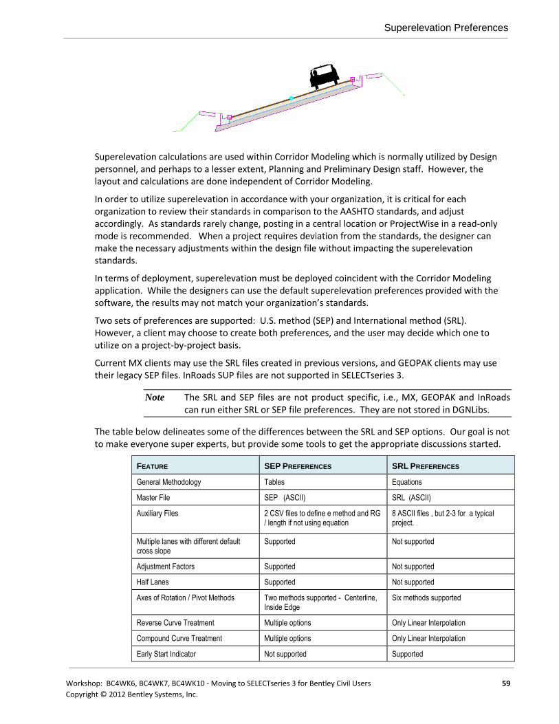
Superelevation Preferences
Workshop: BC4WK6, BC4WK7, BC4WK10 - Moving to SELECTseries 3 for Bentley Civil Users 59
Copyright © 2012 Bentley Systems, Inc.
Superelevation calculations are used within Corridor Modeling which is normally utilized by Design personnel, and perhaps to a lesser extent, Planning and Preliminary Design staff. However, the layout and calculations are done independent of Corridor Modeling.
In order to utilize superelevation in accordance with your organization, it is critical for each organization to review their standards in comparison to the AASHTO standards, and adjust accordingly. As standards rarely change, posting in a central location or ProjectWise in a read-only mode is recommended. When a project requires deviation from the standards, the designer can make the necessary adjustments within the design file without impacting the superelevation standards.
In terms of deployment, superelevation must be deployed coincident with the Corridor Modeling application. While the designers can use the default superelevation preferences provided with the software, the results may not match your organization’s standards.
Two sets of preferences are supported: U.S. method (SEP) and International method (SRL). However, a client may choose to create both preferences, and the user may decide which one to utilize on a project-by-project basis.
Current MX clients may use the SRL files created in previous versions, and GEOPAK clients may use their legacy SEP files. InRoads SUP files are not supported in SELECTseries 3.
Note The SRL and SEP files are not product specific, i.e., MX, GEOPAK and InRoads can run either SRL or SEP file preferences. They are not stored in DGNLibs.
The table below delineates some of the differences between the SRL and SEP options. Our goal is not to make everyone super experts, but provide some tools to get the appropriate discussions started.
FEATURE SEP PREFERENCES SRL PREFERENCES
General Methodology Tables Equations
Master File SEP (ASCII) SRL (ASCII)
Auxiliary Files 2 CSV files to define e method and RG / length if not using equation
8 ASCII files , but 2-3 for a typical project.
Multiple lanes with different default cross slope
Supported Not supported
Adjustment Factors Supported Not supported
Half Lanes Supported Not supported
Axes of Rotation / Pivot Methods Two methods supported - Centerline, Inside Edge
Six methods supported
Reverse Curve Treatment Multiple options Only Linear Interpolation
Compound Curve Treatment Multiple options Only Linear Interpolation
Early Start Indicator Not supported Supported

Superelevation Preferences
60 Workshop: BC4WK6, BC4WK7, BC4WK10 - Moving to SELECTseries 3 for Bentley Civil Users
Copyright © 2012 Bentley Systems, Inc.
Manipulate by Constraints Not supported Supported
Inside edge (pivot changing sides of road)
Not supported Supported
Depending in the composition of your support staff, you may to enlist the expertise of your Standards engineer or Manager, along with key users within your Design section. They will be critical to define, review, and test standards prior to implementation.
First, determine whether your organization is currently using either SEP or SRL files. If so, they can be used with no changes needed.
If you are not using either method, using the chart above, begin by determining whether the SEP or SRL method (or both) fit your organization’s standards. You may use both.
Next, review your standards to the provided default standards. You may also want to obtain files from other governmental transportation agencies and modify.

Workshop: BC4WK6, BC4WK7, BC4WK10 - Moving to SELECTseries 3 for Bentley Civil Users 61
Copyright © 2012 Bentley Systems, Inc.
Appendix A: Setting Up the Workshop in Your Office
OVERVIEW
The workshop can easily be set up to run on your office computer or laptop. Basic steps include:
Copy dataset from DVD to computer Set up
Exercise: Copy the Dataset to Your Computer
Note that many of the workshops use references files and other resources that are path- dependent. Therefore, you may want to utilize the same path as you did in the actual workshop.
Exercise: Check Workstation / Laptop Settings
1. Select the Power product icon on your desktop. In the File Manager dialog, set the User to Nordic. Open checkworkshop.dgn. The Power InRoads projects dialog opens. Do NOT close the dialog; just minimize it.
2. Select Workspace > Configuration from the Power InRoads main menu bar.
3. Scroll down and click on the variable MS_DGNLibList.
4. Check to ensure the workshop path is included as one of the listings. If it is not listed, please advise the instructor and complete the following steps to add the files. Do NOT complete these steps if your configuration is already correct.

Overview
62 Workshop: BC4WK6, BC4WK7, BC4WK10 - Moving to SELECTseries 3 for Bentley Civil Users
Copyright © 2012 Bentley Systems, Inc.
5. Click Select.
6. Choose the design standards and the XIN features file from our project directory. (Both can be done at the same time and have DGNLib extensions).
7. Click Add.
Note You may have to click the small black triangle under Files of Type in order to expand the dialog and see the Add button.
8. Click Done to exit the dialog.
9. Click OK to close the Configuration dialog. When prompted to save the configuration, click Yes.
10. Next we’ll check that your cell library is attached. Select Element > Cells from the Power InRoads main menu bar. Stds2.cel (containing one cell) should be attached. If not, select File > Select File from the Cell Library dialog. Select stds2.cel from your project directory. Close the Cell Library dialog.
11. Lastly, we’ll check the InRoads project defaults. Select File > Power InRoads File > Project Defaults.
12. The Preferences (*.xin) setting should be set to features.xin in your project folder. If it not set or set incorrectly, click Browse and set to the correct path / file.
13. The Project Default Directory should be set to your project folder. If it is not set or set incorrectly, click Browse and set to the correct folder.
14. Click Close to close the Set Projects Defaults dialog. If prompted to Save changes to current configuration, click Yes.
15. Close the MicroStation file.

Workshop: BC4WK6, BC4WK7, BC4WK10 - Moving to SELECTseries 3 for Bentley Civil Users 63
Copyright © 2012 Bentley Systems, Inc.
.


Workshop: BC4WK6, BC4WK7, BC4WK10 - Moving to SELECTseries 3 for Bentley Civil Users 65
Copyright © 2012 Bentley Systems, Inc.
Appendix B: Export to Native
OVERVIEW
“Export to Native” is a functionality within Bentley Civil V8i SELECTseries 3 that allows the user to keep a version of the native geometry database (.GPK, .ALG, .FIL) in synch with the new civil geometry stored within the design file. As a simple example, with this option enabled the user can store an alignment in the design file and that alignment will be automatically stored in the native geometry database as well. Delete that alignment from the design file, and that alignment will be deleted from the native geometry database.
“Export to Native” is not designed to work as an ‘all or nothing’ functionality. It is feature based in that the option to “export to native” must be set to “true” or “false” for each particular feature. For example, an organization may want all civil geometry stored with the feature “Centerline” to be exported to the native geometry database. But for other features (e.g. ““Edge of Pavement”, “Toe of Slope”, “Existing Drainage”, etc.) the organization may not wish to have these features exported.
DESCRIPTION
In this appendix, we’ll explain how “Export to Native” works and how to set it up. In addition, we’ll look at the functionality in more detail so that an organization will have enough information to decide on whether to implement or not.
Note that the functionality we are going to describe, as well as its setup and best practices, for the most part works the same in GEOPAK, InRoads and MX. The main difference of course is how each product originally links to its own native feature files (.DDB, .XIN, .PSS). See Chapter 5 for instructions on how to link up to the native feature files. However, where there are differences in functionality between the products we’ll point that out.
We’ll look at four areas with the regard to the “Export to Native” functionality:
Why Export to Native?
Setup
How it Works
Best Practices
WHY EXPORT TO NATIVE?
Keep in mind that in Bentley Civil V8i SELECTseries 3 there are older applications (e.g. Labeling, Sheet Clipping, etc.) that will continue to rely on the native geometry databases (.GPK, .ALG, .FIL). The “Export to Native” functionality allows the native database to be created and kept in synch ‘automatically’ – forgoing the need for a user to manually export to the native database.
SETUP
Once the link has been made to the native feature files, we can review each feature and its associated settings from Project Explorer. Although there are several tabs (Survey, Plan, 3D, Cross Section, Profile, etc.) that allow an organization to control how this feature will be displayed in each

How it Works
66 Workshop: BC4WK6, BC4WK7, BC4WK10 - Moving to SELECTseries 3 for Bentley Civil Users
Copyright © 2012 Bentley Systems, Inc.
of these areas, only two allow the enabling of the “Export to Native” functionality via the “Auto Export” option – the Plan tab and the Profile tab.
As shown in the following image, these tabs have the options to either enable (set to True) Auto Export or disable (set to False) Auto Export.
In the particular instance of the feature “Centerline” shown in the dialog above, the Plan tab would of course tell the software to Export any horizontal geometry stored with this feature to the native database. The Profile tab would perform a similar function for any vertical geometry stored with the feature “Centerline”.
Note: By default, the Auto Export option is set to “False” for each feature. It is incumbent upon an organization to decide which features if any are to be exported and then enable the option for those particular features only.
HOW IT WORKS
Now that we’ve seen how to enable or disable the Auto Export option for any particular feature, let’s take a look at how it works in practice.
New Geometry
Whenever new civil geometry is stored in a DGN file using a feature that has the Auto Export option enabled, a ‘copy’ of that geometry is automatically exported to (or stored in) the native geometry database. This is probably the simplest case of the Export to Native functionality and the easiest way to explain how it works.
Modified Geometry
Let’s say that you have some existing civil geometry in a DGN file that has been previously Exported to the native database. Now you make changes to that geometry. For example, you could change a radius or rename it. Whenever these changes are made, the corresponding change is made to the geometry in the native database in order to stay in synch.

Appendix B: Export to Native
Workshop: BC4WK6, BC4WK7, BC4WK10 - Moving to SELECTseries 3 for Bentley Civil Users 67
Copyright © 2012 Bentley Systems, Inc.
Deleted Geometry
Similar to the case of the modified geometry, let’s say that you have some existing civil geometry in a DGN file that has been previously Exported to the native database. Now you delete that geometry. When you do that, the corresponding deletion is made to the geometry in the native database in order to stay in synch.
One-Way Only
Keep in mind that this synchronization is a one-way street only. What that means is that while changes to civil geometry in the DGN file are Exported to the native geometry database, the functionality does not operate in reverse. In other words, any changes made to the native geometry database are NOT automatically carried back to the civil geometry in the DGN file.
BEST PRACTICES
Finally, let’s review some things that an organization will want to consider when implementing the Auto Export functionality within Bentley Civil V8i SELECTseries 3.
Naming Conventions
If your native geometry database has any naming conventions (e.g. no spaces, character limitations, etc.), then you will want to keep this in mind when naming civil geometry. Any geometry not meeting the conventions of the native database will not be Exported as desired.
Copying Design Files Containing Civil Geometry
When civil geometry is Exported, there is a ‘rule’ that tells that piece of geometry that it needs to stay in synch with the native database. The ‘rule’ is stored with the geometry itself and does not rely at all on the design file itself. Therefore, any changes made to the ‘copied’ geometry would still be Exported to the native database.
For example, let’s say that you made a new file by copying an existing design file that had Exported civil geometry elements in it. Now let’s say you deleted the civil geometry from that new file. When you do that, the changes would be Exported to the native database and all the corresponding geometry there would be deleted as well.
Manual Export
If an organization chooses NOT to implement the Auto Export functionality, keep in mind that a user still has the ability to Export or “export” the civil geometry manually at any time. This can be done with the Export Geometry tool.
GENERAL GEOMETRY PANEL ICON TOOL
Export Geometry

Best Practices
68 Workshop: BC4WK6, BC4WK7, BC4WK10 - Moving to SELECTseries 3 for Bentley Civil Users
Copyright © 2012 Bentley Systems, Inc.
This page left intentionally blank.

Workshop: BC4WK6, BC4WK7, BC4WK10 - Moving to SELECTseries 3 for Bentley Civil Users 69
Copyright © 2012 Bentley Systems, Inc.
Appendix C: Graphical Filter Library
OVERVIEW
Data is often provided in a variety of formats for consumption into terrain models. These typically include raw graphical elements in both 2D and 3D formats. The Create Terrain by Graphical Filter option requires elements must be 3D and the tool is particularly useful when the source data has consistent (i.e., standardized) element symbology since automation can be achieved.
GRAPHICAL FILTERS
Rather than defining the element symbology for each terrain feature each time a terrain model is created, the information can be stored in a filter group. Numerous groups can be stored and distributed as DGNLib, so the user merely selects the appropriate group, based on the type of features and associated symbology. If none of the groups are applicable, a new filter group can easily be created.
DGNLib Filters
The advantage of the Create Terrain by Graphical Filter tool is that numerous terrain features can be imported simultaneously; the user does not have to select each feature individually, as with the Create Terrain by Elements tool. However, there must be consistency in the source data to utilize this tool.
UPDATE TERRAIN FROM SOURCE
Terrains that have been created using graphical filters retain the creation rule on the Terrain. This is accessible in Project Explorer under the Civil Model – Terrain Models. Mouse Selection of the Rule allows updating the Terrain Source, this reprocesses the rule adding additional graphical elements.

Graphical Filter Tasks
70 Workshop: BC4WK6, BC4WK7, BC4WK10 - Moving to SELECTseries 3 for Bentley Civil Users
Copyright © 2012 Bentley Systems, Inc.
Update Terrain Source
GRAPHICAL FILTER TASKS
Civil Terrain Tasks
Create Terrain Model by Graphical Filter
The command to create / append terrains using pre defined filters or filter groups
Create Terrain Model by Graphical Filter
Graphical Filter Manager
Filter Manager provides the management tools necessary for creating / editing Filter Groups and defining individual
Edit Filter properties lists all selection properties and provides the filter characteristics.
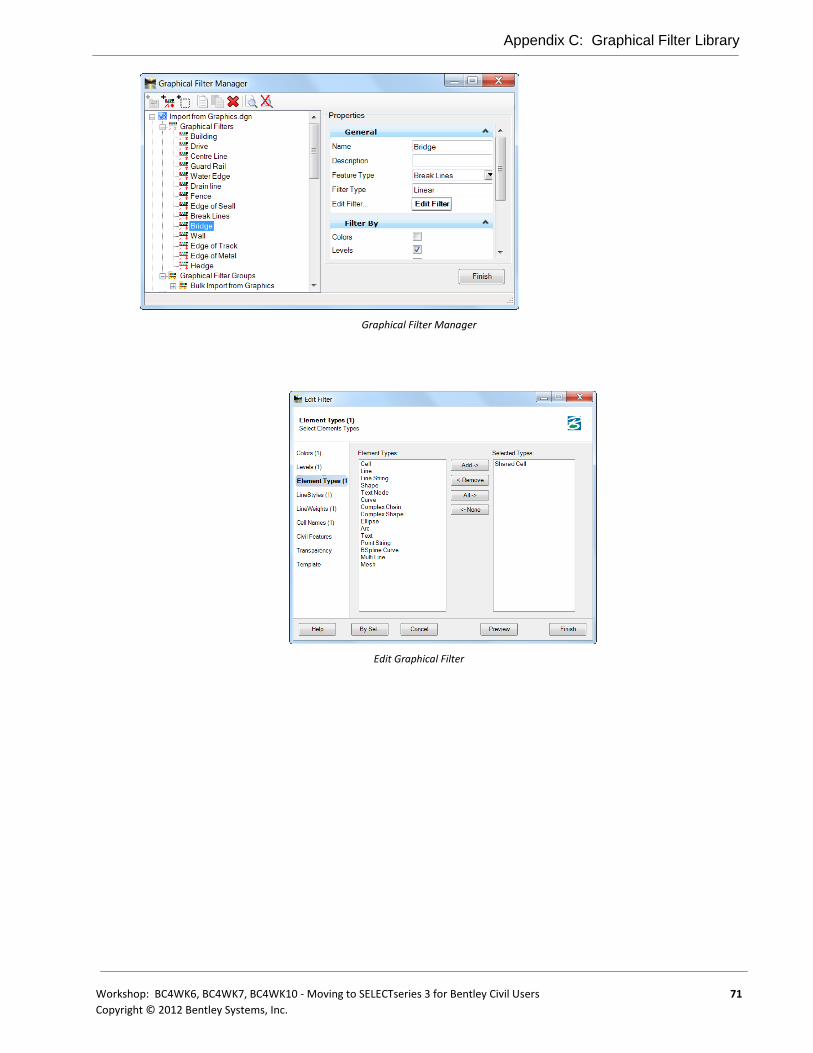
Appendix C: Graphical Filter Library
Workshop: BC4WK6, BC4WK7, BC4WK10 - Moving to SELECTseries 3 for Bentley Civil Users 71
Copyright © 2012 Bentley Systems, Inc.
Graphical Filter Manager
Edit Graphical Filter

Graphical Filter Tasks
72 Workshop: BC4WK6, BC4WK7, BC4WK10 - Moving to SELECTseries 3 for Bentley Civil Users
Copyright © 2012 Bentley Systems, Inc.
This page left intentionally blank.

Workshop: BC4WK6, BC4WK7, BC4WK10 - Moving to SELECTseries 3 for Bentley Civil Users 73
Copyright © 2012 Bentley Systems, Inc.
Appendix D: Civil Report Browser
OVERVIEW
The Civil Report Browser is utilized throughout Bentley Civil to generate and print reports on geometry, corridors, superelevation and a myriad of other topics. Default reports are included within the installation; however, each organization may want to review the reports to determine:
Is the default report the desired report or is there another report that is better suited?
Does the report need customization to include different data, formatting, etc.?
ACCESSING THE BROWSER
While the users access the browser from the report tools, support staff and those creating / editing reports may access the report browser from outside the product. It is located at:
..\PowerGEOPAK\RoadWayDesign\bin
..\PowerInRoads\RoadWayDesign\bin
It’s an executable file: ReportBrowser.exe.

Setting the Defaults
74 Workshop: BC4WK6, BC4WK7, BC4WK10 - Moving to SELECTseries 3 for Bentley Civil Users
Copyright © 2012 Bentley Systems, Inc.
SETTING THE DEFAULTS
Setting the Defaults is accomplished within the Report Browser.

Workshop: BC4WK6, BC4WK7, BC4WK10 - Moving to SELECTseries 3 for Bentley Civil Users 75
Copyright © 2012 Bentley Systems, Inc.
Appendix E: MX Workflows
OVERVIEW
The MX model file provides a single file location where the MX Models are contained, this practice difference from InRoads and GEOPAK that have external files for separate model. This practice affords the MX user some benefits and negatives that as we move towards the new civil tools need to transition the benefits and address the negatives with the new tools.
Typical MX workflows revolve around a structured input file design approach. To aid in the adoption of the new tools additional processes have been implemented to aid in the transition and integrate traditional MX workflows with the new civil tools.
The processes described are specific to MX and require being in an active MX project.
DEALING WITH MX MODELS AND CIVIL FEATURES
Since the MX model file contains many models we need a way to define the active MX model and pick the appropriate MX features for it. This is achieved by way of enhancing the standard feature toolbar with a MX model control.
Without an active model the Feature listing reports civil features appropriate to the MX PSS. The MX PSS needs to have been imported to civil features and this is covered in an earlier chapter.
If no MX model is present the feature list reverts to the configuration variable
MX_DEFAULTCIVILSTYLESET=publicstyles/mxroad.pss
for the default MX styleset and provides corresponding features from that to the civil feature definitions.
The processes associated here are very similar to the MX conversion toolbar for converting CAD graphics to MX string features.
MX Feature Toggle Toolbar

Importing MX Geometry
76 Workshop: BC4WK6, BC4WK7, BC4WK10 - Moving to SELECTseries 3 for Bentley Civil Users
Copyright © 2012 Bentley Systems, Inc.
IMPORTING MX GEOMETRY
The MX model.fil is the single file source for MX models / strings. To simplify the file import geometry process the MX user has the option to import directly from the active projects model file.
Import Geometry from Active MX model
As MX designers we tend refer to Alignments in MX as Master Strings, the reality is the MX geometry in its pure form is stored as G Strings, with M Stings essentially holding the chained / stroked point information associated with the GString, with the two linked by their sub references.
When importing MX geometry to new tools treat M and G strings separately. Importing
G Strings as Alignments with Profile M Strings to 3D linear elements
Import Geometry from Active MX model
Civil Geometry supports multiple profiles per alignment, with only the active profile being used in the creation of the 3D DGN model. The MString profile if holding modified profile over the Gstring can be referenced and set as the active if required.
All geometry transactions between MX and Civil are recorded to the MX project log file
EXPORT OF MX GEOMETRY
During the export of geometry to MX (manual or automatic) only the ‘Active’ civil profile is exported to MX. The respective M & G Strings are automatically created in conjunction with the corresponding linemode for horizontal (Halgn) and vertical (Valgn / Verat). The respective linemode code is written to the MX log file and associated ASCII files are created in ..\mediate\ folder. These input files can then be incorporated back into the the existing input file process.
MX LOG FILE
The MX log file records transactions with the MX Engine and provides a source to develop the input file workflows. To aid in transitioning workflows to Civil Geometry the transactions to import from MX and export to MX are recorded in the log file.

Appendix E: MX Workflows
Workshop: BC4WK6, BC4WK7, BC4WK10 - Moving to SELECTseries 3 for Bentley Civil Users 77
Copyright © 2012 Bentley Systems, Inc.
MAJOR OPTION SCRIPT
Major option script has been enhanced to support more CAD orientated workflows, allowing attachment of reference files (introduced in SELECTseries 1) and further enhancements for SELECTseries 3 to accept MSTN keying and Civil commands.
The import geometry process is captured and written to the MX log file for each string imported in the following format.
script, geomcmd import model=MX TUTORIAL GROUND name=GC10
This command can be put used in the design input file process to facilitate displaying the MX geometry as Civil Geometry and so provides a means of bringing legacy projects held in input files into the dynamic modeling environment provided at SELECTseries 3.
IMPORT TERRAIN MODEL.
During the import of MX models to Civil Terrains the corresponding command line record is written to the log file. This allows a MX user to convert MX models to Civil Terrain models where they will benefit from display and analytical performance enhancements.
script,dtmcmd import model=GROUND MODEL edgemethod=RemoveMaxSide maxsidelength=50 featuredefinition=Existing Ground

Import Terrain model.
78 Workshop: BC4WK6, BC4WK7, BC4WK10 - Moving to SELECTseries 3 for Bentley Civil Users
Copyright © 2012 Bentley Systems, Inc.
This page left intentionally blank.
Workshop: BC4WK6, BC4WK7, BC4WK10 - Moving to SELECTseries 3 for Bentley Civil Users 79
Copyright © 2012 Bentley Systems, Inc.
Glossary
2D Point Feature Contains no elevation (Z). 2D Point Features are defined and stored in plan model.
3D Geometry 3D geometry is created in 3D model by mathematically combining the horizontal and vertical geometry to create 3D elements. These 3D geometry elements in turn define a design model.
3D Model This is created and managed automatically. User can interact with it but this is not usually required. The mathematical combination of Plan Geometry and Profile Geometry is stored in the 3D model.
3D Point Feature 3D points can be defined in plan model or 3D model. They are stored in 3D model but represented in both plan and 3D.
Active Object The current object to which is added all geometry which is created.
Active Profile Of the multiple possible profiles for an element, the active profile is the one used for design. The active profile is combined with the horizontal geometry to build a 3D element which is used in the 3D model.
Active Terrain Model
One terrain model can be designated as “Active”. The active terrain model is the one used to display “existing ground”; in other words the one which displays automatically in a profile model when it is opened. The active terrain model is also the one which is targeted by side slopes unless the template defines a different target by name.
ALG A legacy (proprietary) InRoads file containing coordinate geometry information, superelevation, and alignment information for a specific geometry project.
Alignment A linear feature which serves the special purpose of defining the centerline or baseline of a roadway.
Apply Linear Template
Applies a corridor template along a feature while hiding some of the complexity of creating a corridor.
Apply Surface Template
Applies a corridor template to a terrain model for the purpose of creating components (such as pavement layers) under the terrain model.
Arc Definition Curve definition method generally used in roadway applications. The radius R is used to define the curve and is defined by the equation R=5729.58/D where the degree of curvature D is the central angle subtended by a 100-foot arc. Set in the Design File Settings > Civil Formatting under Radius Settings. See also Chord Definition.
Aspect An angular measure of the direction that the face of a surface is oriented. The format of the value is dependent on angular settings In the DGN file.
Base Geometry In many instances the geometry element will be trimmed. The original (or base), untrimmed element is always preserved as it is the storage for the rule.

Glossary
80 Workshop: BC4WK6, BC4WK7, BC4WK10 - Moving to SELECTseries 3 for Bentley Civil Users
Copyright © 2012 Bentley Systems, Inc.
Boundary (Terrain Model)
Used to constrain the external boundary of the terrain model. No triangles are created outside the boundary. In addition, any point data outside the boundary is ignored.
Break Line A surface feature consisting of a collection of spatial coordinates that have an implied linear relationship. No triangle side (in the triangulated surface) can cross over a break line.
Break Void A closed area of missing or obscured data that uses the elevations of each vertex, while the void lines between successive void coordinates are inserted as break lines. Therefore, break voids change the slope and elevations of the TIN surface.
Cardinal Points One of the points used to define the geometry of an alignment. Cardinal points include PC, PT, PI, and CC points for horizontal geometry and VPC, VPI and VPT for vertical geometry.
Centroid (triangle) Geometric center of a triangle in a terrain model.
Chord Definition Curve definition method generally used in railway applications. The radius R is used to define the curve, and is defined by the equation R=50/SIN(0.5*D) where the degree of curvature D is the central angle subtended by a 100-foot chord. See also Arc Definition.
Civil Cell Used as a mechanism to preconfigure commonly used complex geometric layouts. These layouts will commonly be stored in DGNLIB files for reuse across multiple projects but it is possible and sometimes useful to store directly in an active DGN file for use in that single location. The civil cell will contain horizontal geometry and can also contain the vertical geometry.
Civil Message Center
Used to display a continuous updating log of Civil messages, including warnings and errors. As errors and warnings are resolved, they are removed from the list. New messages are added whenever the conditions warrant. Most messages relate to civil geometry, superelevation, and corridor modeling.
Civil Template A civil design concept used most often for corridor modeling but also has other applications. The Civil Template defines the cross-sectional shape of the object being modeled. This cross-section is then “extruded along” a 3D geometry element to form the final model. The corridor template can create or target features such as road edges. The result is the creation of a corridor.
Clipping Reference Clipping allows you to remove areas of overlap when working with multiple corridors in a single surface. For example, in a corridor intersected by a crossing roadway, clipping would be used to remove all overlapped features within the intersection.
Complex Terrain Model
A terrain model created by merging or appending two or more terrain models.
Context Toolbox When an element is selected, hovering over the element provide a heads-up and context sensitive toolbar which pops up at the cursor. This toolbar provides a few of the most commonly used tools which operate on the element selected element type. The first tool in this toolbar is always Quick Properties.
Contour A linear symbol representing points of equal elevation relative to a given datum.
Glossary
Workshop: BC4WK6, BC4WK7, BC4WK10 - Moving to SELECTseries 3 for Bentley Civil Users 81
Copyright © 2012 Bentley Systems, Inc.
Contour, Isopach Contours of a delta terrain model which represent cut and fill values as contours, not elevations. A positive contour represents fill, while a negative contour is cut.
Contour, Major The primary elevation line indicating a specific elevation in a surface model. Usually major contours are drawn with a heavier line weight or using a different color. Elevation text labels are usually drawn in association with major contours.
Contour, Minor A secondary elevation line indicating a specific elevation in a surface model. Minor contours are often drawn without special color or weight indexing and without elevation text labels.
Corridor A civil object used for modeling a roadway and is automatically managed by the corridor modeling tools.
Cross Section Model
DGN models (extracted perpendicular to defined horizontal geometry) with special station elevation coordinates defined and other specialized capabilities such as view exaggeration. Cross section stations match the interval in the template drop when a corridor is used as the basis. When horizontal geometry is utilized, the left / right offsets and interval are user-defined.
Curve Stroking Stroking is the process of automatically adding shots to the terrain model or corridor by interpolating new shots from the curved sections of the data. This distance is used to interpolate new shots along the curved element in corridor processing and applying linear templates. This value is used as a perpendicular minimum distance from chords generated along the arc. Chords are drawn along the arc and the perpendicular distance is measured from the middle of each chord to the arc. If this distance is larger than the Curve Stroking, the process is repeated with a shorter chord length. This process is repeated until the end of the curve is reached. The flatter the curve, the fewer number of points will be calculated. The steeper the curve, the greater number of points that will be calculated.
DDB File GEOPAK file (Design DataBase) which contains features definitions, associated symbology and annotation settings.
Delta Terrain Model
A surface containing data derived from the difference in elevation between two terrain models or a terrain model and a plane.
Dialog The tool settings box for the active command. The dialog shows all available options for a command. For most civil commands, most of the time, the dialog can be hidden and ignored since the user is given all necessary instruction and inputs by way of the cursor prompt. The dialog is necessary for configuring command customizations.
Drape The process of vertically projecting elements onto a surface so that the element elevations are defined by the surface.
Drape Void A closed area of missing or obscured data where the void coordinates are not included in the triangulation. Voids are inserted post triangulation. The void coordinates and lines are draped on the TIN surface. Even though a user must provide an elevation for the Drape Void vertices, the user elevations are changed to the elevation of the TIN surface at the XY Drape Void coordinate position.

Glossary
82 Workshop: BC4WK6, BC4WK7, BC4WK10 - Moving to SELECTseries 3 for Bentley Civil Users
Copyright © 2012 Bentley Systems, Inc.
Element Template MicroStation concept which allows preconfigured definitions for symbology and other miscellaneous display of MicroStation elements and civil features.
End Condition A specialized component of a corridor template which provides information tie into active surface.
End Condition Exception
Used to modify the behavior of an end condition solution without requiring the use of additional template drops. When an end condition exception is added, it must be edited to change its behavior.
Export to Native Option to automatically or manually push horizontal and vertical geometry into native products (InRoads - ALG, MX - PSS and GEOPAK - GPK).
Feature A Feature is anything that can be seen or located and is a physical part of your design, representing a real world thing. A feature’s definition is one of its properties. At any given time in the design process, the feature will have a Horizontal Geometry, a Vertical Geometry, 3D Geometry or a combination to define its location.
Feature Definition Used to define options when creating features. These are the items which are created in advance, usually used across multiple projects and define symbology, annotation and quantities. The feature definition is assigned (usually) in the plan model and profile/3D feature definitions follow from there.
Feature Name Each Feature can have a name.
Gap When a feature is trimmed the part(s) which are invisible on the base geometry.
GPK A legacy (proprietary) GEOPAK database containing coordinate geometry information.
Graphical Filter Using in developing terrain models, an automated way of storing search settings for graphic elements when creating terrain models using 3D element. A graphical filter can be created for each feature (i.e., spots, breaks, voids) then the filters can be defined as a Graphical filter group.
Heads Up Prompt Command instructions are given in a heads up and dynamic prompt which floats at the cursor.
Horizontal Geometry
The elements which define the horizontal layout of the design. These elements are 2D elements even if the DGN model is 3D. Horizontal Geometry may be points, lines, arcs, spirals, splines or any combination in a complex element.
Interval When a feature is trimmed the part(s) which are visible on the base geometry.
Island Closed area used to place within a void, i.e., islands in the middle of rivers, lakes, etc.
Key Station Additional station added to the corridor to force processing at the particular location.
LIDAR (Light Detection And Ranging) is an optical scanning technology which scans ground and other physical features to produce a 3D model.

Glossary
Workshop: BC4WK6, BC4WK7, BC4WK10 - Moving to SELECTseries 3 for Bentley Civil Users 83
Copyright © 2012 Bentley Systems, Inc.
Linear Feature In plan model, composed of lines, arcs, spirals, splines or combinations of these. In profile model, composed of lines, parabola, splines or combinations of these.
Linear Stroking Stroking is the process of automatically adding shots to the terrain model or corridor by interpolating new shots from the linear sections of the data. Linear stroking is measured along the element. Interpolated vertices are added whenever the distance between the vertices is greater than the linear stroking value (in master units).
Manipulators The heads up, on-screen editing interface. Only the most common properties are presented in manipulators. Manipulators are in two types: graphical and text
Overlay Vertical Adjustment
Within Corridor Model, tool used to develop a vertical geometry (based on milling and overlay parameters) and apply to the corridor.
Parametric Constraints
Used to set up constraint value overrides for specified station ranges.
Plan Model The usual DGN model, used for laying out horizontal geometry. Best practices will dictate that this is a 2D DGN model but 3D DGN model can be used. This is where geometric layouts and corridor definitions are kept. The geometric layouts are not only alignments but also edges, parking, striping, sidewalks, etc.
Point Features Defined by a single X, Y (Z optional) location. A point need not be a feature. It may be defined as a non-featurized point by way of AccuDraw, Civil AccuDraw, Snap or a data point. Non featurized points are use to control the construction of Linear Features.
Point Cloud A set of vertices in a 3D coordinate system and these vertices are defined the by X, Y and Z coordinates. Point clouds are usually created by 3D scanners. These devices measure a large number of points on the surface of an object and output a point cloud as a data file. The point cloud represents the visible surface of the object that has been scanned or digitized.
Point Control Used to modify the behavior of points in a template. These controls take precedence (they override) over existing constraints on the point.
Project Explorer MicroStation's interface for browsing elements in a DGN file. Extended by civil to accommodate specialized civil needs.
PSS File MX file (Plans Style Set) which provides the graphical representation for the MX string features.
Reference Element The rule for some geometry is a calculation from another element. This other element is the reference element.
Secondary Alignment
Used to modify the direction of cross section processing. By default, as any given station, the cross section is created orthogonal to the main alignment/feature. If a secondary alignment exists, then that portion of the cross section which lies outside the secondary alignment will be orthogonal to the secondary alignment instead of the main alignment.
SEP File / Method Uses the superelevation settings which originated in GEOPAK.

Glossary
84 Workshop: BC4WK6, BC4WK7, BC4WK10 - Moving to SELECTseries 3 for Bentley Civil Users
Copyright © 2012 Bentley Systems, Inc.
SMD File GEOPAK file (Survey Manager Database) which contains survey features definitions and associated element and textual settings.
Spot Elevation A set of X, Y, Z coordinates representing a point on the terrain model surface. There is no implied relationship between regular points.
SRL File / Method Uses the superelevation settings which originated in MX
Superelevation Lane
The closed area defined by the superelevation tools used for the limits of transition calculations and pivoting location.
Superelevation Section
Area along a horizontal geometry element, where superelevation will be calculated.
Target Aliasing Used to create the desired results when working with multiple surfaces without having to edit the template from the template library. Target aliases can also be used so that one corridor can target the solution of another corridor.
Template Drop An area (usually defined by station limits) along a corridor to which a specific template is applied.
Template Library A file that stores definitions for templates, generally with an ITL file extension.
Template Transition
The transition indicator occurs in the corridor between templates of differing names.
Terrain Model A three-dimensional DGN element defined by spots, break lines, voids, holes, contours to model a surface on the earth.
Tooltips When hovering the cursor over an element or a handle, a tooltip is shown which gives explanatory information.
Trace Slope Upstream - The indicated path follows the steepest ascent from a user-defined point through the terrain model terminating at a high point or the edge of the terrain model. Downstream - The indicated path follows the steepest descent from a user-defined point through the terrain model terminating at a low point or the edge of the terrain model.
Vertical Alignment A linear feature in profile model which serves the special purpose of defining the elevations of an alignment.
Vertical Geometry The elements which define the vertical layout of a corresponding horizontal geometry element. These vertical elements are 2D and are stored in a profile model.
Void Closed shape to demarcate areas of missing data or obscure areas. No point or break data located within the void area is utilized and no triangles are created inside the void areas. The Void coordinates are included in the triangulation and void lines between successive void coordinates are inserted as drape lines on the surface. Therefore, they do not change the slope or elevations of the surface.
Watershed Defined by either a low point within the terrain model or a low edge point along the terrain model edge, it's the closed area wherein all water would drain to the low point.

Glossary
Workshop: BC4WK6, BC4WK7, BC4WK10 - Moving to SELECTseries 3 for Bentley Civil Users 85
Copyright © 2012 Bentley Systems, Inc.
XIN File InRoads file which contains features definitions, associated styles, annotation, and other settings.

Glossary
86 Workshop: BC4WK6, BC4WK7, BC4WK10 - Moving to SELECTseries 3 for Bentley Civil Users
Copyright © 2012 Bentley Systems, Inc.


![FOR...Bentley WaterCAD V8i (SELECTseries 1) [08.11.01.32] Bentley Systems, Inc. Haestad Methods Solution Water Model.wtg Center. HIGH HGL NO DEMAND. FlexTable: Pipe Table (Water Model.wtg)](https://static.fdocuments.in/doc/165x107/611cbb157fee8c396150a92e/-bentley-watercad-v8i-selectseries-1-08110132-bentley-systems-inc-haestad.jpg)