Bella Sky Hotel - Start | Sky Hotel Fans | Air Handling Units | Air Distribution Products | Air...
36
Bella Sky Hotel Fans | Air Handling Units | Air Distribution Products | Air Conditioning | Fire Safety | Air Curtains and Heating Products | Tunnel Fans Systemair DFC and IFC Modular Air Handling Unit for Data Center Cooling
Transcript of Bella Sky Hotel - Start | Sky Hotel Fans | Air Handling Units | Air Distribution Products | Air...
Bella Sky Hotel
Fans | Air Handling Units | Air Distribution Products | Air Conditioning | Fire Safety | Air Curtains and Heating Products | Tunnel Fans
Systemair DFC and IFCModular Air Handling Unit for Data Center Cooling

Copyright: Systemair SLU1. edition 2016
We accept no liability for printingerrors or alterations of products.
The dimensions and data used in this catalogue are a guideline only.Accurate calculations must be made in our selection program
for Data Center CoolingModular Air Handling Units
3 DCC DFC and IFC units |
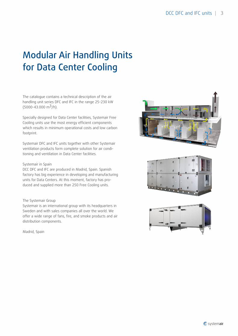
The catalogue contains a technical description of the airhandling unit series DFC and IFC in the range 25-230 kW(5000-43.000 m3/h).
Specially designed for Data Center facilities, Systemair Free Cooling units use the most energy efficient components which results in minimum operational costs and low carbon footprint.
Systemair DFC and IFC units together with other Systemair ventilation products form complete solution for air condi-tioning and ventilation in Data Center facilities.
Systemair in SpainDCC DFC and IFC are produced in Madrid, Spain. Spanish factory has big experience in developing and manufacturing units for Data Centers. At this moment, factory has pro-duced and supplied more than 250 Free Cooling units.
The Systemair GroupSystemair is an international group with its headquarters inSweden and with sales companies all over the world. Weoffer a wide range of fans, fire, and smoke products and airdistribution components.
Madrid, Spain
Contents
| DCC DFC and IFC units4
Introduction . . . . . . . . . . . . . . . . . . . . . . . . . . . . . . 3DCC DFC and IFC . . . . . . . . . . . . . . . . . . . . . . . . . . . . . . 5About the DCC DFC and IFC . . . . . . . . . . . . . . . . . . . . . . . . . . . . . . 6Product Information . . . . . . . . . . . . . . . . . . . . . . . . . . . . . . 8Standards and Certifications . . . . . . . . . . . . . . . . . . . . . . . . . . . . . . 9Combination Examples . . . . . . . . . . . . . . . . . . . . . . . . . . . . . 10Functions . . . . . . . . . . . . . . . . . . . . . . . . . . . . . 14Damper . . . . . . . . . . . . . . . . . . . . . . . . . . . . . 18Damper . . . . . . . . . . . . . . . . . . . . . . . . . . . . . 19Mixing Damper . . . . . . . . . . . . . . . . . . . . . . . . . . . . . 20Compact Filter . . . . . . . . . . . . . . . . . . . . . . . . . . . . . 21Bag Filter . . . . . . . . . . . . . . . . . . . . . . . . . . . . . 22Plate Heat Exchanger . . . . . . . . . . . . . . . . . . . . . . . . . . . . . 24Heating Coil . . . . . . . . . . . . . . . . . . . . . . . . . . . . . 26Cooling Coil . . . . . . . . . . . . . . . . . . . . . . . . . . . . . 27Air Humidifier . . . . . . . . . . . . . . . . . . . . . . . . . . . . . 28Plug Fan . . . . . . . . . . . . . . . . . . . . . . . . . . . . . 30Sound Attenuator . . . . . . . . . . . . . . . . . . . . . . . . . . . . . 32Inspection Section . . . . . . . . . . . . . . . . . . . . . . . . . . . . . 33Empty Section . . . . . . . . . . . . . . . . . . . . . . . . . . . . . 33Outdoor Air Section . . . . . . . . . . . . . . . . . . . . . . . . . . . . . 34Supporting Legs . . . . . . . . . . . . . . . . . . . . . . . . . . . . . 35Base Frame . . . . . . . . . . . . . . . . . . . . . . . . . . . . . 35Dimensions for Ducts . . . . . . . . . . . . . . . . . . . . . . . . . . . . . 36Duct Connection Part . . . . . . . . . . . . . . . . . . . . . . . . . . . . . 37
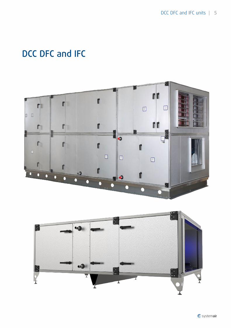
DCC DFC and IFC
5 DCC DFC and IFC units |
About the DCC DFC and IFC
| DCC DFC and IFC units6
DCC DFC and IFC units are designed as a Modular air handling unit. Each function is placed into an air handling unit casing consisting of one or more modules.The modular functions can be config-ured for different applications to make up the heart of Data Center cooling system. The flexibility makes it possible to optimize the air han-dling unit for each project. Sizes and airflowsDCC DFC and IFC units come in a range of 6 different sizes, with capac-ities from 25-230 kW or 5000-43.000 m3/h, making it possible to always find optimized solution for any given requirement.
CasingThe casing protects the inside func-tions and is very effective forthermal and sound insulation.
FunctionsData Center modular unit features a number of well-dimensioned func-tions, presenting a choice between different Free Cooling systems,types of heat exchangers, cooling coils, humidifying and dehumidifying systems.
Selection programThe product selection program,ensures optimal design of the air handling unit functions. The program is very user-friendly and makes it possible to quickly and easily combine air handling unit functions and per-form technical calculations.Selection program calculates and optimizes the energy consumption, generates pPUE figures and OPEX graphics.The program uses a number of com-bination examples or basic versions. For these examples one can quickly add or remove features in order to easily design the desired air handling unit. Principal drawings, plus logicalconstruction and presentation of technical data provide easy overview.
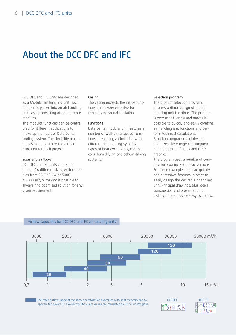
Airflow capacities for DCC DFC and IFC air handling units
Indicates airflow range at the shown combination examples with heat recovery and by specific fan power 2,1 kW/(m3/s). The exact values are calculated by Selection Program.
50000 m3/h30000200001000050003000
1053210,7 15 m3/s
150120
6050
4020
DCC DFC DCC IFC
7 DCC DFC and IFC units |
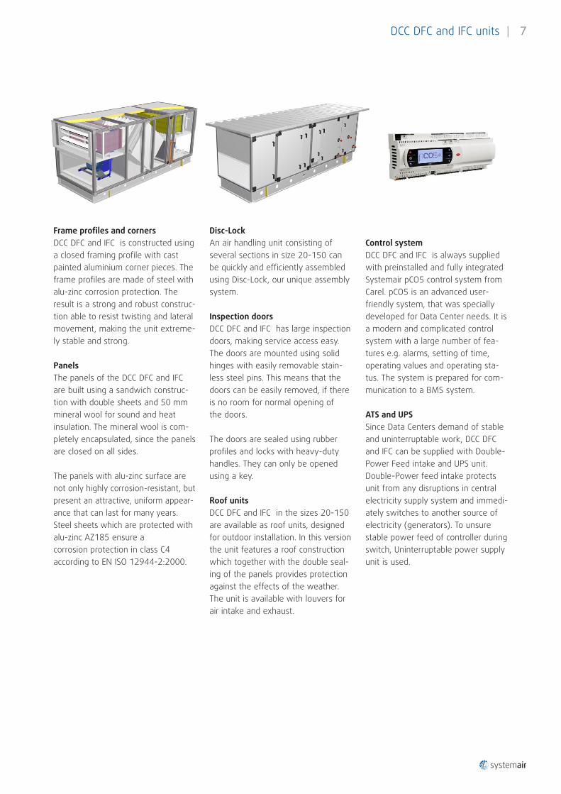
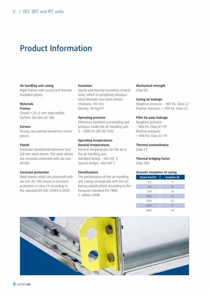
Frame profiles and cornersDCC DFC and IFC is constructed using a closed framing profile with cast painted aluminium corner pieces. The frame profiles are made of steel with alu-zinc corrosion protection. The result is a strong and robust construc-tion able to resist twisting and lateral movement, making the unit extreme-ly stable and strong.
PanelsThe panels of the DCC DFC and IFC are built using a sandwich construc-tion with double sheets and 50 mm mineral wool for sound and heat insulation. The mineral wool is com-pletely encapsulated, since the panels are closed on all sides.
The panels with alu-zinc surface are not only highly corrosion-resistant, but present an attractive, uniform appear-ance that can last for many years. Steel sheets which are protected with alu-zinc AZ185 ensure a corrosion protection in class C4 according to EN ISO 12944-2:2000.
Disc-LockAn air handling unit consisting of several sections in size 20-150 can be quickly and efficiently assembled using Disc-Lock, our unique assembly system.
Inspection doorsDCC DFC and IFC has large inspection doors, making service access easy. The doors are mounted using solid hinges with easily removable stain-less steel pins. This means that the doors can be easily removed, if there is no room for normal opening of the doors.
The doors are sealed using rubber profiles and locks with heavy-duty handles. They can only be opened using a key.
Roof unitsDCC DFC and IFC in the sizes 20-150 are available as roof units, designed for outdoor installation. In this version the unit features a roof construction which together with the double seal-ing of the panels provides protection against the effects of the weather. The unit is available with louvers for air intake and exhaust.
Control systemDCC DFC and IFC is always supplied with pre installed and fully integrated Systemair pCO5 control system from Carel. pCO5 is an advanced user-friendly system, that was specially developed for Data Center needs. It is a modern and complicated control system with a large number of fea-tures e.g. alarms, setting of time, operating values and operating sta-tus. The system is prepared for com-munication to a BMS system.
ATS and UPSSince Data Centers demand of stableand uninterruptable work, DCC DFC and IFC can be supplied with Double-Power Feed intake and UPS unit.Double-Power feed intake protects unit from any disruptions in central electricity supply system and immedi-ately switches to another source of electricity (generators). To unsure stable power feed of controller during switch, Uninterruptable power supply unit is used.
Product Information
| DCC DFC and IFC units8
Air handling unit casingRigid frames with sound and thermal insulated panels.
MaterialsFramesClosed 1,3/1,5 mm steel profile. Surface: Alu-zinc AZ 185.
CornersStrong cast painted aluminium corner pieces.
PanelsInsulation sandwiched between two 0,8 mm steel sheets. The steel sheets are corrosion protected with alu-zinc AZ185.
Corrosion protectionSteel sheets which are protected with alu-zinc AZ 185 ensure a corrosion protection in class C4 according to the standard EN ISO 12944-2:2000.
InsulationSound and thermal insulating mineral wool, which is completely encapsu-lated between two steel sheets.Thickness: 50 mm.Density: 50 kg/m3.
Operating pressureDifference between surrounding and pressure inside the air handling unit:0 - 2000 Pa (DV 20-150)
Operating temperaturesGeneral temperatures General temperatures for the air in the air handling unit: Standard design: -40/+40 ˚C Special design: -40/+60 ˚C
ClassificationsThe performance of the air handling unit casing corresponds with the fol-lowing classifications according to the European standard EN 1886, 2. edition 2008.
Mechanical strengthClass D2
Casing air leakage Negative pressure: - 400 Pa: Class L2Positive pressure: + 700 Pa: Class L2
Filter by-pass leakage Negative pressure: - 400 Pa: Class G1-F9Positive pressure: + 400 Pa: Class G1-F9
Thermal transmittanceClass T2
Thermal bridging factorClass TB3
Acoustic insulation of casing Octave band Hz Insulation dB
125 17
250 23
500 24
1000 23
2000 25
4000 31
8000 38
Standards and Certifications
9 DCC DFC and IFC units |
The DCC DFC and IFC design is based on the demands in the following CEN and ISO standards:
EN 305:1997Heat exchangers. Definition and test procedures.
EN 308:1997Heat exchangers. Test procedures.
EN 779:2012Particulate air filters for general ventilation.
EN 1216:1999Heat exchangers
EN 1751:2014Aerodynamic testing of dampers and valves.
EN 1886:2008Air handling units. Mechanical performance.
EN 13053:2011Ratings and performance for units and components.
EN 13779:2007Ventilation for non-residential build-ings. Performance requirements.
EN 60204-1:2006Machine safety. Electrical equipment of machines.
EN ISO 3741:2010Determination of sound power level in reverberation rooms.
EN ISO 5136:2009Determination of sound power level in a duct.
EN ISO 12100:2011Safety of machinery.
EN ISO 12944-2:2000Corrosion protection. Classification of environments.
ISO 9001:2008 certificationDCC DFC and IFC air handling units are developed and manufactured in Spain. The Quality management sys-tem at the factory is certified accord-ing to the standard EN ISO 9001:2008 by Bureau Veritas Certification.
Machinery directiveDCC DFC and IFC air handling units are manufactured according to the safety demands of the EU Machinery Directive 2006/42/EC. This is con-firmed through the issurance of cor-responding Declaration of Conformity and CE label for units with factory installed unit control system.
Combination Examples
| DCC DFC and IFC units10
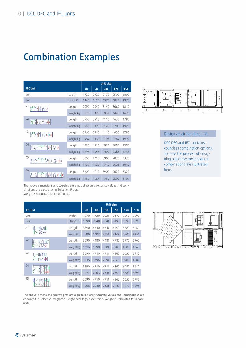
The above dimensions and weights are a guideline only. Accurate values and combinations are calculated in Selection Program.* Height excl. legs/base frame. Weight is calculated for indoor units.
The above dimensions and weights are a guideline only. Accurate values and com-binations are calculated in Selection Program. Weight is calculated for indoor units.
DCC DFC and IFC contains countless combination options. To ease the process of desig-ning a unit the most popular combinations are illustrated here.
Design an air handling unit
DFC Unit
Unit size
40 50 60 120 150
Unit Width 1720 2020 2170 2590 2890
Unit Height* 1145 1195 1370 1820 1970
D1 Length 2990 2540 3140 3660 3810
Weight kg 820 825 934 1440 1620
D2 Length 3960 3510 4110 4630 4780
Weight kg 950 995 1145 1700 1925
D3 Length 3960 3510 4110 4630 4780
Weight kg 987 1033 1194 1769 1994
D4 Length 4630 4410 4930 6050 6350
Weight kg 1298 1356 1499 2363 2735
D5 Length 5600 4710 5900 7020 7320
Weight kg 1428 1526 1710 2623 3040
D6 Length 5600 4710 5900 7020 7320
Weight kg 1465 1564 1759 2692 3109
IFC Unit
Unit size
20 40 50 60 120 150
Unit Width 1270 1720 2020 2170 2590 2890
Unit Height* 1590 2040 2340 2490 3390 3690
S1 Length 3590 4340 4340 4490 5680 5460
Weight kg 980 1682 2050 2162 3900 4451
S2 Length 3590 4480 4480 4780 5970 5900
Weight kg 1116 1890 2308 2285 4303 4663
S3 Length 3590 4710 4710 4860 6050 5980
Weight kg 1035 1796 2090 2268 3980 4683
S4 Length 3590 4710 4710 4860 6050 5980
Weight kg 1171 2003 2348 2391 4383 4895
S5 Length 3590 4710 4710 4860 6050 5980
Weight kg 1208 2040 2386 2440 4470 4993
11 DCC DFC and IFC units |
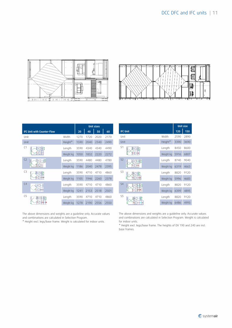
The above dimensions and weights are a guideline only. Accurate values and combinations are calculated in Selection Program. * Height excl. legs/base frame. Weight is calculated for indoor units.
The above dimensions and weights are a guideline only. Accurate values and combinations are calculated in Selection Program. Weight is calculated for indoor units. * Height excl. legs/base frame. The heights of DV 190 and 240 are incl. base frames.
IFC Unit with Counter-Flow
Unit sizes
20 40 50 60
Unit Width 1270 1720 2020 2170
Unit Height* 1590 2040 2340 2490
C1 Length 3590 4340 4340 4490
Weight kg 1050 1832 2220 2272
C2 Length 3590 4480 4480 4780
Weight kg 1186 2040 2478 2395
C3 Length 3590 4710 4710 4860
Weight kg 1105 1946 2260 2378
C4 Length 3590 4710 4710 4860
Weight kg 1241 2153 2518 2501
C5 Length 3590 4710 4710 4860
Weight kg 1278 2190 2556 2550
IFC Unit
Unit size
120 150
Unit Width 2590 2890
Unit Height* 3390 3690
S1 Length 8450 8600
Weight kg 5916 6807
S2 Length 8740 9040
Weight kg 6319 4663
S3 Length 8820 9120
Weight kg 5996 4683
S4 Length 8820 9120
Weight kg 6399 4895
S5 Length 8820 9120
Weight kg 6486 4993
Functions
| DCC DFC and IFC units12
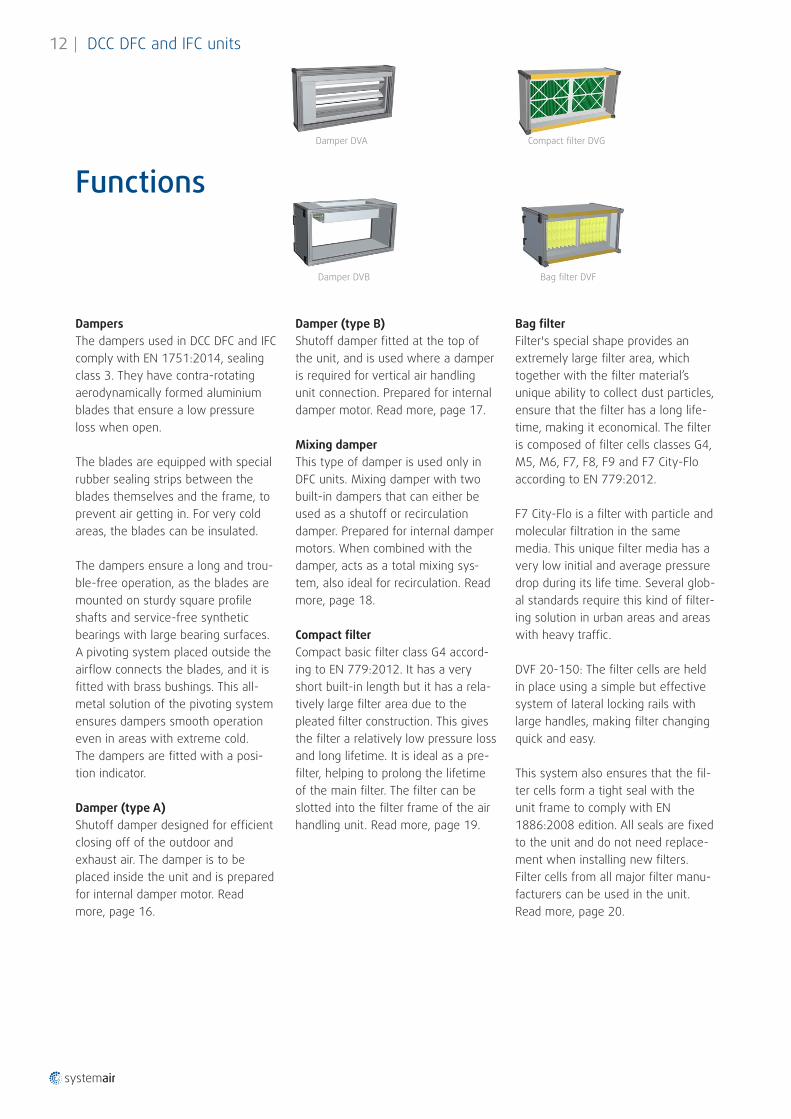
DampersThe dampers used in DCC DFC and IFC comply with EN 1751:2014, sealing class 3. They have contra-rotating aerodynamically formed aluminium blades that ensure a low pressure loss when open.
The blades are equipped with special rubber sealing strips between the blades themselves and the frame, to prevent air getting in. For very cold areas, the blades can be insulated.
The dampers ensure a long and trou-ble-free operation, as the blades are mounted on sturdy square profile shafts and service-free synthetic bearings with large bearing surfaces. A pivoting system placed outside the airflow connects the blades, and it is fitted with brass bushings. This all-metal solution of the pivoting system ensures dampers smooth operation even in areas with extreme cold.The dampers are fitted with a posi-tion indicator.
Damper (type A)Shutoff damper designed for efficient closing off of the outdoor and exhaust air. The damper is to be placed inside the unit and is prepared for internal damper motor. Read more, page 16.
Damper DVA
Damper DVB Bag filter DVF
Damper (type B)Shutoff damper fitted at the top of the unit, and is used where a damper is required for vertical air handling unit connection. Prepared for internal damper motor. Read more, page 17.
Mixing damperThis type of damper is used only in DFC units. Mixing damper with two built-in dampers that can either be used as a shutoff or recirculation damper. Prepared for internal damper motors. When combined with the damper, acts as a total mixing sys-tem, also ideal for recirculation. Read more, page 18.
Compact filterCompact basic filter class G4 accord-ing to EN 779:2012. It has a very short built-in length but it has a rela-tively large filter area due to the pleated filter construction. This gives the filter a relatively low pressure loss and long lifetime. It is ideal as a pre-filter, helping to prolong the lifetime of the main filter. The filter can be slotted into the filter frame of the air handling unit. Read more, page 19.
Bag filterFilter's special shape provides an extremely large filter area, which together with the filter material’s unique ability to collect dust particles, ensure that the filter has a long life-time, making it economical. The filter is composed of filter cells classes G4, M5, M6, F7, F8, F9 and F7 City-Flo according to EN 779:2012.
F7 City-Flo is a filter with particle and molecular filtration in the same media. This unique filter media has a very low initial and average pressure drop during its life time. Several glob-al standards require this kind of filter-ing solution in urban areas and areas with heavy traffic.
DVF 20-150: The filter cells are held in place using a simple but effective system of lateral locking rails with large handles, making filter changing quick and easy.
This system also ensures that the fil-ter cells form a tight seal with the unit frame to comply with EN 1886:2008 edition. All seals are fixed to the unit and do not need replace-ment when installing new filters. Filter cells from all major filter manu-facturers can be used in the unit.Read more, page 20.
Compact filter DVG
13 DCC DFC and IFC units |
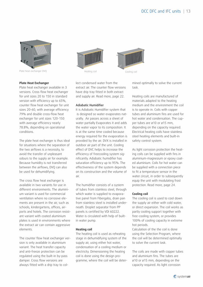
Plate Heat ExchangerPlate heat exchanger available in 3 versions. Cross flow heat exchanger for unit sizes 20 to 150 in standard version with efficiency up to 65%, counter flow heat exchanger for unit sizes 20-60, with average efficiency 79% and double cross-flow heat exchanger for unit sizes 120-150 with average efficiency nearly 78.8%, depending on operational conditions.
The plate heat exchanger is thus ideal for situations where the separation of the two airflows is a necessity, to avoid the transfer of unpleasant odours to the supply air for example. Because humidity is not transferred between the airflows, DVQ can also be used for dehumidifying.
The cross flow heat exchanger is available in two variants for use in different environments. The alumini-um variant is used for commercial ventilation where no corrosive ele-ments are present in the air, such as schools, kindergartens, offices, air-ports and hotels. The corrosion resist-ant variant with coated aluminium plates is used in environments where the extract air can contain aggressive elements.
The counter flow heat exchanger ver-sion is only available in aluminium variant. The heat transfer capacity and anti-freeze protection can be regulated using the built-in by-pass damper. Cross flow versions are always fitted with a drip tray to col-
Plate heat exchanger DVQ
lect condensed water from the extract air. The counter flow versions have drip tray fitted in both extract and supply air. Read more, page 22.
Adiabatic Humidifier It is Adiabatic Humidifier system that is designed so water evaporates nat-urally. Air passes across a sheet of water partially Evaporates it and adds the water vapor to its composition. It is at the same time cooled because energy required for the evaporation is provided by the air. DVX is installed in outdoor air part of the unit. Cooling effect of DVC helps to increase the efficiency of freecooling system sig-nificantly. Adiabatic humidifier has saturation efficiency up to 95%. The effectiveness of the system depends on its construction and the volume of air.
The humidifier consists of a system of tubes from stainless steel, through which water is supplied to evapora-tive panel from Fibergalss, drain pan from stainless steel is installed under-neath. Droplet separator from PP panels is certified by VDI 60222.Water is circulated with help of built-in water pump.
Heating coilThe heating coil is used as reheatingstage in dehumidifying system of the supply air, using either hot water, condensation of a cooling medium or electricity. Dimensioning the heating coil is done using the design pro-gramme, where the coil will be deter-
mined optimally to solve the current task.
Heating coils are manufactured of materials adapted to the heating medium and the environment the coil is to operate in. Coils with copper tubes and aluminium fins are used for hot water and condensation. The cup-per tubes are ø10 or ø15 mm, depending on the capacity required. Electrical heating coils have stainless steel heating elements and built-in safety control system.
As light corrosion protection the heat-ing coils can be supplied with fins in aluminium-magnesium or epoxy coat-ed aluminium. Coils for hot water can be supplied with a connection piece to fit a temperature sensor in the water circuit, in order to subsequently equip the unit with modulating frost protection. Read more, page 24.
Cooling coilThe cooling coil is used to cool down the supply air either with cold water, or direct expansion. The coil works as partly cooling support together with free-cooling system, or provides 100% of cooling capacity in extreme hot periods.Calculation of the the coil is done using the Selection Program, where the coil will be determined optimally to solve the current task.
The coils are made with copper tubes and aluminium fins. The tubes are ø10 or ø15 mm, depending on the capacity required. As light corrosion
Heating coil Cooling coil
Functions
| DCC DFC and IFC units14
protection the cooling coils can be supplied with fins in aluminium-mag-nesium or epoxy coated aluminium.
Cooling coils for direct expansion have the liquid distributor located in the unit. The expansion valve is fitted on the connection pipe inside the unit. Cooling coils are fitted with drip tray. The drain outlet must be con-nected to a water trap with sufficient locking height. The cooling coil can be supplied with a built-in droplet eliminator. The coil is fully built-in in the unit as standard. Read more, page 25.
Steam humidifierSteam humidifier is used for humidi-fying air that is supplied to data cent-er. Steam humidifier is used for very accurate control of humidity level, without influence on it’s temperature.
Steam humidifier consists of External unit, where steam is prepared and supplied through steam hose to steam manifold that is installed inside the DCC unit section.Read more on page 28.
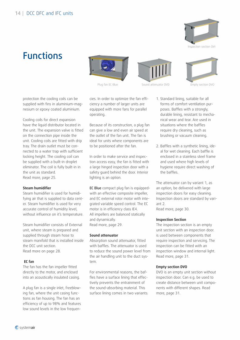
EC fan The fan has the fan impeller fitted directly to the motor, and enclosed into an acoustically insulated casing.
A plug fan is a single inlet, freeblow-ing fan, where the unit casing func-tions as fan housing. The fan has an efficiency of up to 98% and features low sound levels in the low frequen-
cies. In order to optimize the fan effi-ciency a number of larger units are equipped with more fans for parallel operating.
Because of its construction, a plug fan can give a low and even air speed at the outlet of the fan unit. The fan is ideal for units where components are to be positioned after the fan.
In order to make service and inspec-tion access easy, the fan is fitted with a large hinged inspection door with a safety guard behind the door. Interior lighting is an option.
EC Blue compact plug fan is equipped-with an effective composite impeller, and EC external rotor motor with inte-grated variable speed control. The EC motor is in efficiency class IE4.All impellers are balanced statically and dynamically. Read more, page 29. Sound attenuatorAbsorption sound attenuator, fitted with baffles. The attenuator is used to reduce the sound power level from the air handling unit to the duct sys-tem.
For environmental reasons, the baf-fles have a surface lining that effec-tively prevents the entrainment of the sound-absorbing material. This surface lining comes in two variants:
1. Standard lining, suitable for all forms of comfort ventilation pur-poses. Baffles with a strongly, durable lining, resistant to mecha-nical wear and tear. Are used in situations where the baffles require dry cleaning, such as brushing or vacuum cleaning.
2. Baffles with a synthetic lining, ide-al for wet cleaning. Each baffle is enclosed in a stainless steel frame and used where high levels of hygiene require direct washing of the baffles.
The attenuator can by variant 1, as an option, be delivered with large inspection doors for easy cleaning. Inspection doors are standard by vari-ant 2. Read more, page 30.
Inspection SectionThe inspection section is an empty unit section with an inspection door. is used between components that require inspection and servicing. The inspection can be fitted with an inspection window and internal light. Read more, page 31.
Empty section DVO DVO is an empty unit section without inspection door. Can e.g. be used to create distance between unit compo-nents with different shapes. Read more, page 31.
Plug fan EC Blue Sound attenuator DVD
Inspection section DVI
Empty section DVO
15 DCC DFC and IFC units |
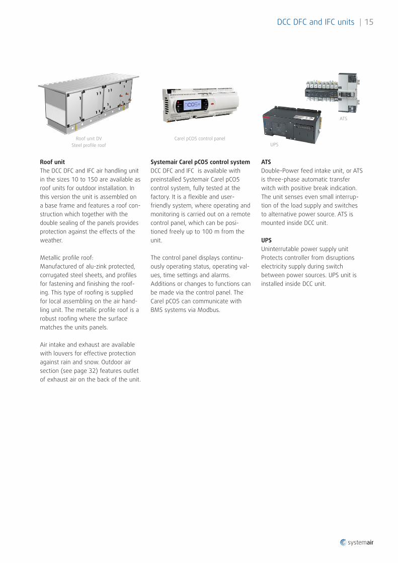
Roof unit The DCC DFC and IFC air handling unit in the sizes 10 to 150 are available as roof units for outdoor installation. In this version the unit is assembled on a base frame and features a roof con-struction which together with the double sealing of the panels provides protection against the effects of the weather.
Metallic profile roof:Manufactured of alu-zink protected, corrugated steel sheets, and profiles for fastening and finishing the roof-ing. This type of roofing is supplied for local assembling on the air hand-ling unit. The metallic profile roof is a robust roofing where the surface matches the units panels.
Air intake and exhaust are available with louvers for effective protection against rain and snow. Outdoor air section (see page 32) features outlet of exhaust air on the back of the unit.
Systemair Carel pCO5 control systemDCC DFC and IFC is available with pre installed Systemair Carel pCO5 control system, fully tested at the factory. It is a flexible and user-friendly system, where operating and monitoring is carried out on a remote control panel, which can be posi-tioned freely up to 100 m from the unit.
The control panel displays continu-ously operating status, operating val-ues, time settings and alarms. Additions or changes to functions can be made via the control panel. The Carel pCO5 can communicate with BMS systems via Modbus.
Roof unit DV Steel profile roof
Carel pCO5 control panel
ATSDouble-Power feed intake unit, or ATSis three-phase automatic transfer witch with positive break indication.The unit senses even small interrup-tion of the load supply and switches to alternative power source. ATS is mounted inside DCC unit.
UPSUninterrutable power supply unitProtects controller from disruptionselectricity supply during switch between power sources. UPS unit is installed inside DCC unit.
ATS
UPS
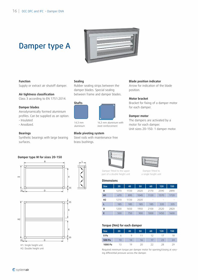
Damper type A
16 | DCC DFC and IFC • Damper DVA
FunctionSupply or extract air shutoff damper.
Air tightness classificationClass 3 according to EN 1751:2014.
Damper bladesAerodynamically formed aluminium profiles. Can be supplied as an option:• Insulated• Anodized.
BearingsSynthetic bearings with large bearing surfaces.
Damper fitted to the upper part of a double height unit
SealingRubber sealing strips between the damper blades. Special sealing between frame and damper blades.
Shafts
14,3 mm aluminium
16,3 mm aluminium with steel reinforcement
Blade pivoting systemSteel rods with maintenance free brass bushings.
Damper fitted to a single height unit
Blade position indicatorArrow for indication of the blade position.
Motor bracketBracket for fixing of a damper motor for each damper.
Damper motorThe dampers are activated by a motor for each damper.Unit sizes 20-150: 1 damper motor.
3535
3535
35
H2
H1: Single height unitH2: Double height unit
Damper type M for sizes 20-150
Size 20 40 50 60 120 150
B 1270 1720 2020 2170 2590 2890
H1 670 895 1045 1120 1570 1720
H2 1270 1720 2020 - - -
L 185 185 185 185 335 335
D 1200 1650 1950 2100 2520 2820
E 500 750 900 1000 1450 1600
Size 20 40 50 60 120 150
0 Pa 6 9 11 12 17 18
500 Pa 10 14 16 17 23 24
1000 Pa 13 19 20 22 28 29
Dimensions
Torque (Nm) for each damper
Required minimum torque per damper motor for opening/closing at vary-ing differential pressure across the damper.
17 DCC DFC and IFC • Damper DVA |
Damper type B
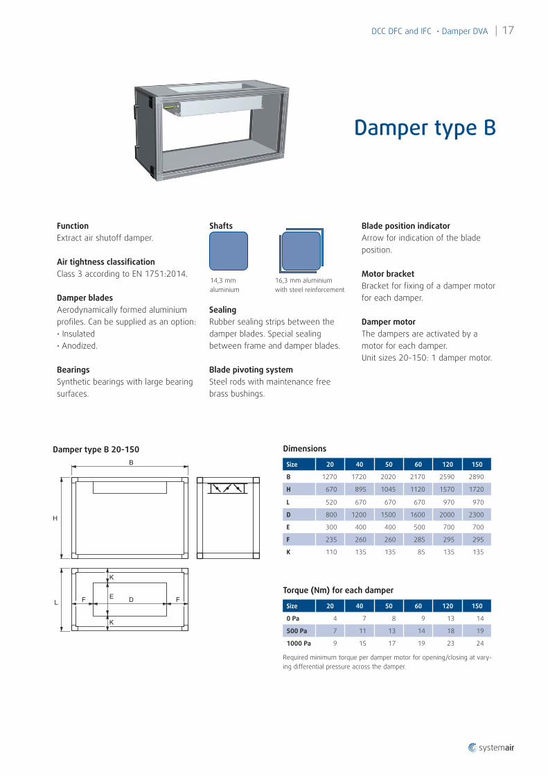
FunctionExtract air shutoff damper.
Air tightness classificationClass 3 according to EN 1751:2014.
Damper bladesAerodynamically formed aluminium profiles. Can be supplied as an option:• Insulated• Anodized.
BearingsSynthetic bearings with large bearing surfaces.
Shafts
14,3 mm aluminium
16,3 mm aluminium with steel reinforcement
SealingRubber sealing strips between the damper blades. Special sealing between frame and damper blades.
Blade pivoting systemSteel rods with maintenance free brass bushings.
Blade position indicatorArrow for indication of the blade position.
Motor bracketBracket for fixing of a damper motor for each damper.
Damper motorThe dampers are activated by a motor for each damper.Unit sizes 20-150: 1 damper motor.
L
Damper type B 20-150
Size 20 40 50 60 120 150
B 1270 1720 2020 2170 2590 2890
H 670 895 1045 1120 1570 1720
L 520 670 670 670 970 970
D 800 1200 1500 1600 2000 2300
E 300 400 400 500 700 700
F 235 260 260 285 295 295
K 110 135 135 85 135 135
Size 20 40 50 60 120 150
0 Pa 4 7 8 9 13 14
500 Pa 7 11 13 14 18 19
1000 Pa 9 15 17 19 23 24
Dimensions
Torque (Nm) for each damper
Required minimum torque per damper motor for opening/closing at vary-ing differential pressure across the damper.
Mixing Damper DVM
18 | DCC DFC and IFC • Mixing Damper DVM
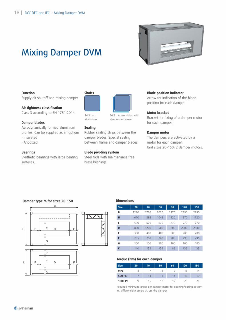
FunctionSupply air shutoff and mixing damper.
Air tightness classificationClass 3 according to EN 1751:2014.
Damper bladesAerodynamically formed aluminium profiles. Can be supplied as an option:• Insulated• Anodized.
BearingsSynthetic bearings with large bearing surfaces.
L
Damper type M for sizes 20-150
Shafts
14,3 mm aluminium
16,3 mm aluminium with steel reinforcement
SealingRubber sealing strips between the damper blades. Special sealing between frame and damper blades.
Blade pivoting systemSteel rods with maintenance free brass bushings.
Size 20 40 50 60 120 150
B 1270 1720 2020 2170 2590 2890
H 670 895 1045 1120 1570 1720
L 520 670 670 670 970 970
D 800 1200 1500 1600 2000 2300
E 300 400 400 500 700 700
F 235 260 260 285 295 295
G 100 100 100 100 100 100
K 110 135 135 85 135 135
Size 20 40 50 60 120 150
0 Pa 4 7 8 9 13 14
500 Pa 7 11 13 14 18 19
1000 Pa 9 15 17 19 23 24
Dimensions
Torque (Nm) for each damper
Required minimum torque per damper motor for opening/closing at vary-ing differential pressure across the damper.
Blade position indicatorArrow for indication of the blade position for each damper.
Motor bracketBracket for fixing of a damper motor for each damper.
Damper motorThe dampers are activated by a motor for each damper.Unit sizes 20-150: 2 damper motors.
19 DCC DFC and IFC • Mixing Damper DVM |
Prefilter
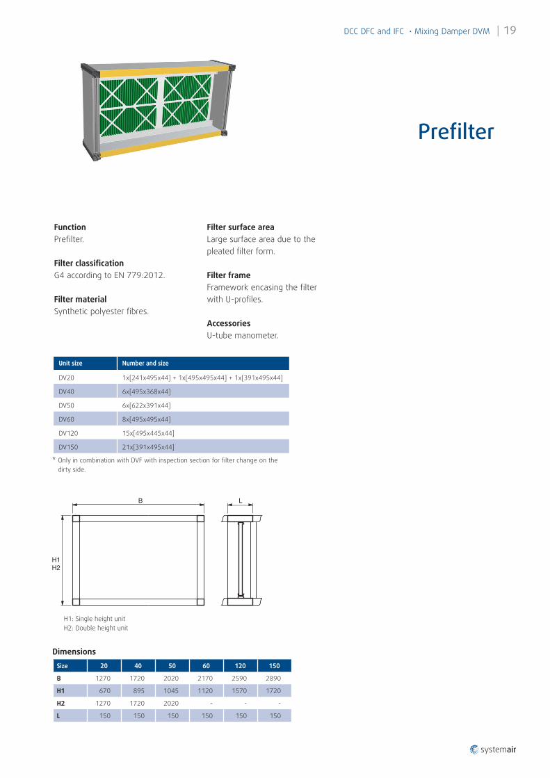
FunctionPrefilter.
Filter classificationG4 according to EN 779:2012.
Filter materialSynthetic polyester fibres.
Unit size Number and size
DV20 1x[241x495x44] + 1x[495x495x44] + 1x[391x495x44]
DV40 6x[495x368x44]
DV50 6x[622x391x44]
DV60 8x[495x495x44]
DV120 15x[495x445x44]
DV150 21x[391x495x44]
* Only in combination with DVF with inspection section for filter change on the dirty side.
Filter surface areaLarge surface area due to the pleated filter form.
Filter frameFramework encasing the filter with U-profiles.
AccessoriesU-tube manometer.
H1: Single height unitH2: Double height unit
DimensionsSize 20 40 50 60 120 150
B 1270 1720 2020 2170 2590 2890
H1 670 895 1045 1120 1570 1720
H2 1270 1720 2020 - - -
L 150 150 150 150 150 150
20 | DCC DFC and IFC • Bag Filter DVF
Prefilter
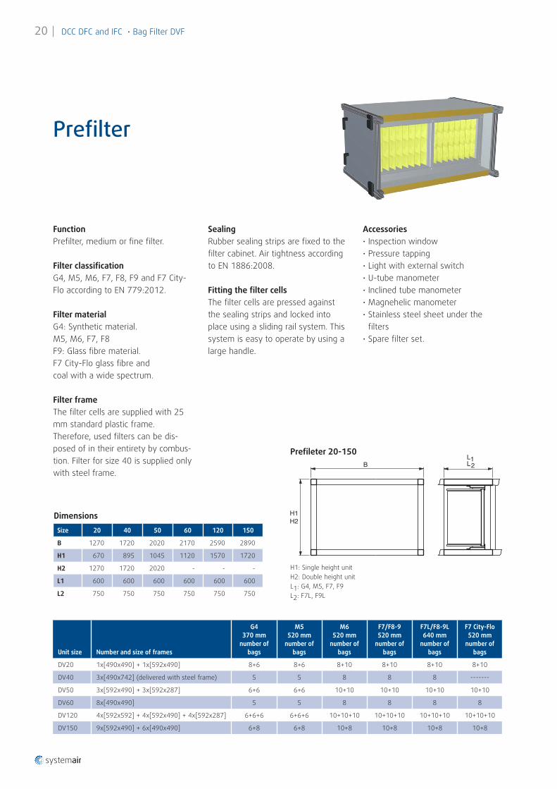
FunctionPrefilter, medium or fine filter.
Filter classificationG4, M5, M6, F7, F8, F9 and F7 City-Flo according to EN 779:2012.
Filter materialG4: Synthetic material.M5, M6, F7, F8 F9: Glass fibre material. F7 City-Flo glass fibre and coal with a wide spectrum.
Filter frameThe filter cells are supplied with 25 mm standard plastic frame. Therefore, used filters can be dis-posed of in their entirety by combus-tion. Filter for size 40 is supplied only with steel frame.
SealingRubber sealing strips are fixed to the filter cabinet. Air tightness according to EN 1886:2008.
Fitting the filter cellsThe filter cells are pressed against the sealing strips and locked into place using a sliding rail system. This system is easy to operate by using a large handle.
Accessories• Inspection window • Pressure tapping • Light with external switch • U-tube manometer • Inclined tube manometer • Magnehelic manometer • Stainless steel sheet under the
filters • Spare filter set.
H1: Single height unitH2: Double height unitL1: G4, M5, F7, F9 L2: F7L, F9L
Prefileter 20-150
Size 20 40 50 60 120 150
B 1270 1720 2020 2170 2590 2890
H1 670 895 1045 1120 1570 1720
H2 1270 1720 2020 - - -
L1 600 600 600 600 600 600
L2 750 750 750 750 750 750
Unit size Number and size of frames
G4 370 mm
number of bags
M5 520 mm
number of bags
M6 520 mm
number of bags
F7/F8-9 520 mm
number of bags
F7L/F8-9L 640 mm
number of bags
F7 City-Flo 520 mm
number of bags
DV20 1x[490x490] + 1x[592x490] 8+6 8+6 8+10 8+10 8+10 8+10
DV40 3x[490x742] (delivered with steel frame) 5 5 8 8 8 -------
DV50 3x[592x490] + 3x[592x287] 6+6 6+6 10+10 10+10 10+10 10+10
DV60 8x[490x490] 5 5 8 8 8 8
DV120 4x[592x592] + 4x[592x490] + 4x[592x287] 6+6+6 6+6+6 10+10+10 10+10+10 10+10+10 10+10+10
DV150 9x[592x490] + 6x[490x490] 6+8 6+8 10+8 10+8 10+8 10+8
Dimensions
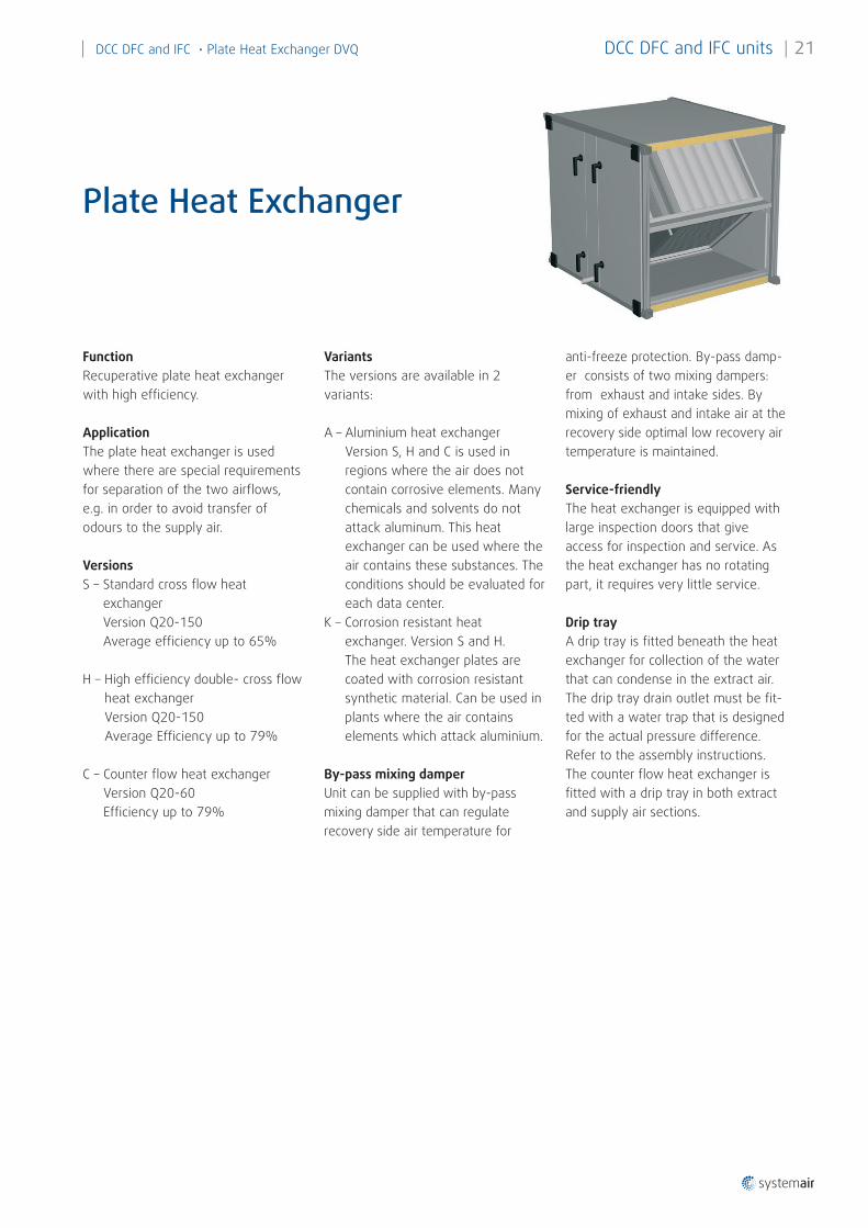
Plate Heat Exchanger
21 DCC DFC and IFC units | | DCC DFC and IFC • Plate Heat Exchanger DVQ
FunctionRecuperative plate heat exchanger with high efficiency.
ApplicationThe plate heat exchanger is used where there are special requirements for separation of the two airflows, e.g. in order to avoid transfer of odours to the supply air.
VersionsS – Standard cross flow heat
exchanger Version Q20-150 Average efficiency up to 65%
H – High efficiency double- cross flow heat exchanger Version Q20-150 Average Efficiency up to 79%
C – Counter flow heat exchanger Version Q20-60 Efficiency up to 79%
VariantsThe versions are available in 2 variants:
A – Aluminium heat exchanger Version S, H and C is used in regions where the air does not contain corrosive elements. Many chemicals and solvents do not attack aluminum. This heat exchanger can be used where the air contains these substances. The conditions should be evaluated for each data center.
K – Corrosion resistant heat exchanger. Version S and H. The heat exchanger plates are coated with corrosion resistant synthetic material. Can be used in plants where the air contains elements which attack aluminium.
By-pass mixing damperUnit can be supplied with by-pass mixing damper that can regulate recovery side air temperature for
anti-freeze protection. By-pass damp-er consists of two mixing dampers: from exhaust and intake sides. By mixing of exhaust and intake air at the recovery side optimal low recovery air temperature is maintained.
Service-friendlyThe heat exchanger is equipped with large inspection doors that give access for inspection and service. As the heat exchanger has no rotating part, it requires very little service.
Drip trayA drip tray is fitted beneath the heat exchanger for collection of the water that can condense in the extract air. The drip tray drain outlet must be fit-ted with a water trap that is designed for the actual pressure difference. Refer to the assembly instructions. The counter flow heat exchanger is fitted with a drip tray in both extract and supply air sections.
| DCC DFC and IFC units22 DCC DFC and IFC • Plate Heat Exchanger
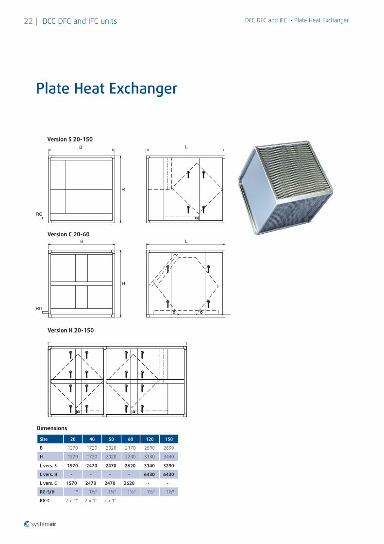
Plate Heat Exchanger
Version C 20-60
Version H 20-150
Size 20 40 50 60 120 150
B 1270 1720 2020 2170 2590 2890
H 1270 1720 2020 2240 3140 3440
L vers. S 1570 2470 2470 2620 3140 3290
L vers. H - - - - 6430 6430
L vers. C 1570 2470 2470 2620 - -
RG-S/H 1" 1½" 1½" 1½" 1½" 1½"
RG-C 2 x 1" 2 x 1" 2 x 1"
Dimensions
Version S 20-150
23 DCC DFC and IFC units | | DCC DFC and IFC • Plate Heat Exchanger DVQ
Air heater
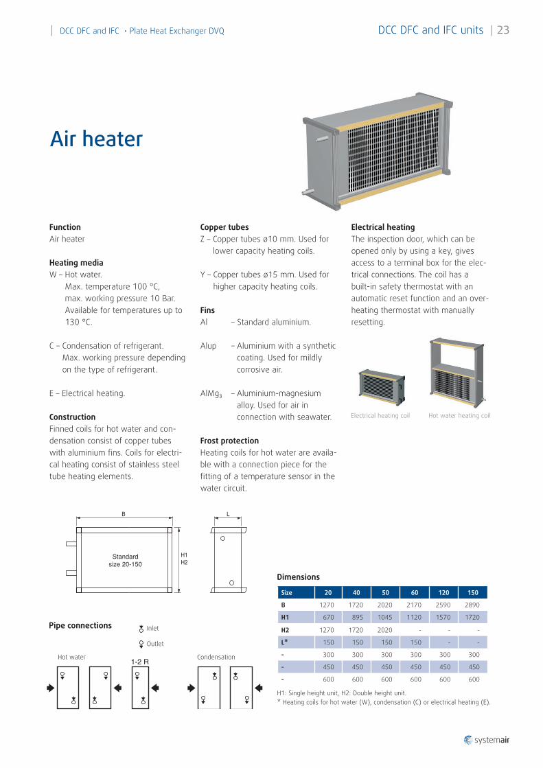
FunctionAir heater
Heating mediaW – Hot water.
Max. temperature 100 °C, max. working pressure 10 Bar. Available for temperatures up to 130 °C.
C – Condensation of refrigerant. Max. working pressure depending on the type of refrigerant.
E – Electrical heating.
ConstructionFinned coils for hot water and con-densation consist of copper tubes with aluminium fins. Coils for electri-cal heating consist of stainless steel tube heating elements.
StandardDVH 10-150
MAXDVH 10-150
Electrical heating coil Hot water heating coil
Hot water Condensation
Pipe connections Inlet
Outlet
Copper tubesZ – Copper tubes ø10 mm. Used for
lower capacity heating coils.
Y – Copper tubes ø15 mm. Used for higher capacity heating coils.
FinsAl – Standard aluminium.
Alup – Aluminium with a synthetic coating. Used for mildly corrosive air.
AlMg₃ – Aluminium-magnesium alloy. Used for air in connection with seawater.
Frost protectionHeating coils for hot water are availa-ble with a connection piece for the fitting of a temperature sensor in the water circuit.
Electrical heatingThe inspection door, which can be opened only by using a key, gives access to a terminal box for the elec-trical connections. The coil has a built-in safety thermostat with an automatic reset function and an over-heating thermostat with manually resetting.
Size 20 40 50 60 120 150
B 1270 1720 2020 2170 2590 2890
H1 670 895 1045 1120 1570 1720
H2 1270 1720 2020 - - -
L* 150 150 150 150 - -
- 300 300 300 300 300 300
- 450 450 450 450 450 450
- 600 600 600 600 600 600
Dimensions
H1: Single height unit, H2: Double height unit.* Heating coils for hot water (W), condensation (C) or electrical heating (E).
Standardsize 20-150
Air cooler
| DCC DFC and IFC units24 DCC DFC and IFC • Plate Heat Exchanger
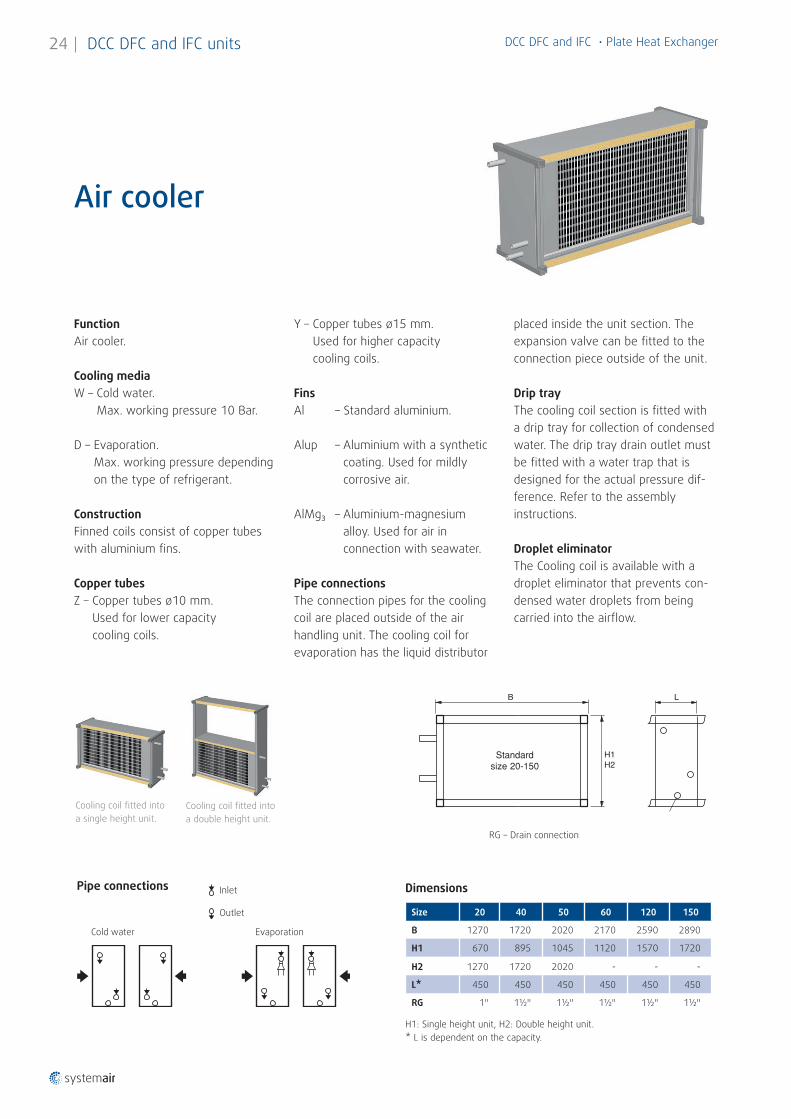
FunctionAir cooler.
Cooling mediaW – Cold water.
Max. working pressure 10 Bar.
D – Evaporation. Max. working pressure depending on the type of refrigerant.
ConstructionFinned coils consist of copper tubes with aluminium fins.
Copper tubesZ – Copper tubes ø10 mm.
Used for lower capacity cooling coils.
Y – Copper tubes ø15 mm. Used for higher capacity cooling coils.
FinsAl – Standard aluminium.
Alup – Aluminium with a synthetic coating. Used for mildly corrosive air.
AlMg₃ – Aluminium-magnesium alloy. Used for air in connection with seawater.
Pipe connectionsThe connection pipes for the cooling coil are placed outside of the air hand ling unit. The cooling coil for evaporation has the liquid distributor
placed inside the unit section. The expansion valve can be fitted to the connection piece outside of the unit.
Drip trayThe cooling coil section is fitted with a drip tray for collection of condensed water. The drip tray drain outlet must be fitted with a water trap that is designed for the actual pressure dif-ference. Refer to the assembly instructions.
Droplet eliminatorThe Cooling coil is available with a droplet eliminator that prevents con-densed water droplets from being carried into the airflow.
Cooling coil fitted into a single height unit.
Cooling coil fitted into a double height unit.
StandardDVK 10-150
MAXDVK 10-150
RG – Drain connection
Cold water Evaporation
Pipe connections Inlet
Outlet Size 20 40 50 60 120 150
B 1270 1720 2020 2170 2590 2890
H1 670 895 1045 1120 1570 1720
H2 1270 1720 2020 - - -
L* 450 450 450 450 450 450
RG 1" 1½" 1½" 1½" 1½" 1½"
Dimensions
H1: Single height unit, H2: Double height unit.* L is dependent on the capacity.
Standardsize 20-150
Air Humidifier
25 DCC DFC and IFC units | | DCC DFC and IFC • Air Humidifier DVX
Function The function is based on the natural process that water evaporates when air passes a wet surface. By uptake of water vapor in the air, the tempera-ture will decrease due to the fact that heat for the evaporation comes from the air. This is an adiabatic cooling, which means that the enthalpy con-tent of the air is unchanged during the process. This ensures that humidi-fication occurs without releasing drops, unless this is effected by entrainment. Entrainment may be avoided by passing the humidification elements with a suitable low speed or by mounting droplet eliminators, which can handle this.
ApplicationThe humidifier is placed in the recov-ery side before heat exchanger to increase indirect free-cooling effect because of adiabatic effect in areas with high outdoor temperature and low humidity.
ConstructionThe humidifier is designed as a com-plete unit that fits the internal dimen-sions of a section of length 970 mm in the units 20 to 150. The unit com-
prises humidification elements, tray and frame made of stainless steel AISI 304, circulation pump, balancing valves for irrigation, overflow, valve for adjusting bleed off, float valve for controlling the water supply to the tray and valve for emptying the tray. Droplet eliminator is included if nec-essary and sensor for protection of pump at low water level. The drain is led out of the sec-tion, and can be selected either on the inspection side or the backside. The drain must be connected to a water trap with sufficient locking height.
Humidification elementsHU-CELL humidification elements are stainless steel frames which contains corrugated fiberglass plates arranged in cross-channel configuration. The corrugated cross-channel configura-tion ensures that the air is in contact with a large surface area for evapora-tion, and at the same time provides a low pressure drop. The glass fiber material is impregnated with a stabi-lizing and absorbent additive which makes it possible to absorb water without loss of stability. The element is of inorganic material, and is there-fore not a feed source for bacteria
and mould. The material contains sil-ver ions, which acts as a growth inhibitor. This increases the resistance to the growth of microorganisms and helps to release deposits from the water on the material, so that this remains clean. Silver ions are encap-sulated in a chemical mixture, which ensures that their particles do not dissolve to either water or air. The elements are supplied in the follow-ing thicknesses 75 mm, 100 mm, 125 mm and 150 mm. This makes it possible to optimize the pressure drop depending on the desired humidification/cooling requirement.
Technical dataThe Selection Program calculates all important data such as temperature, relative and absolute humidity after the humidifier, pressure drop and water consumption etc.
| DCC DFC and IFC units26 DCC DFC and IFC • Air Humidifier DVX |
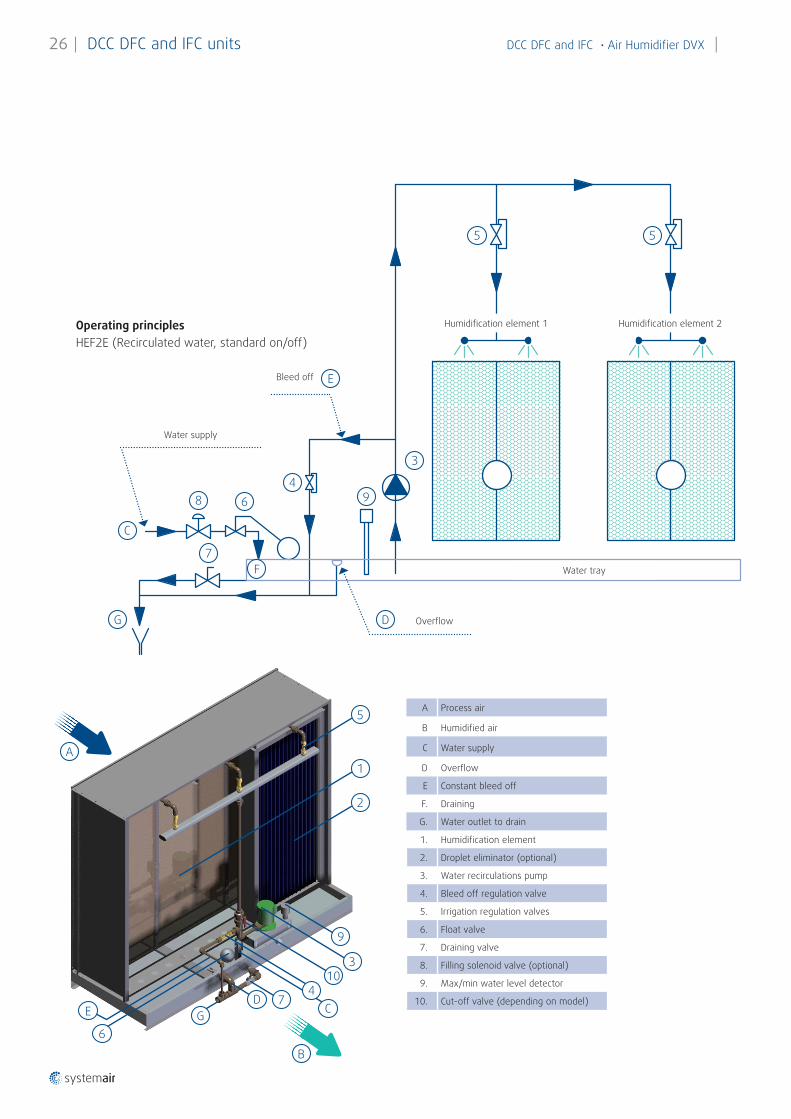
A Process air
B Humidified air
C Water supply
D Overflow
E Constant bleed off
F. Draining
G. Water outlet to drain
1. Humidification element
2. Droplet eliminator (optional)
3. Water recirculations pump
4. Bleed off regulation valve
5. Irrigation regulation valves
6. Float valve
7. Draining valve
8. Filling solenoid valve (optional)
9. Max/min water level detector
10. Cut-off valve (depending on model)
Operating principles HEF2E (Recirculated water, standard on/off)
Water supply
Overflow
Bleed off
Water tray
Humidification element 2
3
C
F
E
D
7
68
5 5
49
G
4C
7DG
6
E
2
5
1
103
9
B
A
Humidification element 1
Steam Humidifier
27 DCC DFC and IFC units | | DCC DFC and IFC • Plug Fan DVE
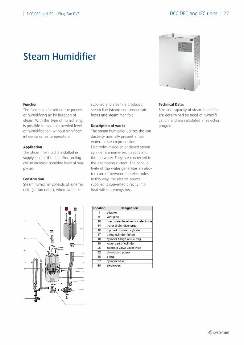
FunctionThe function is based on the processof humidifying air by injection of steam. With this type of humidifying is possible to maintain needed level of humidification, without significant influence on air temperature.
Application:The steam manifold is installed in supply side of the unit after cooling coil to increase humidity level of sup-ply air.
Construction:Steam humidifier consists of external unit, (carton outer), where water is
supplied and steam is produced, steam line (steam and condensate hose) and steam manifold.
Description of work: The steam humidifier utilizes the con-ductivity normally present in tap water for steam production. Electrodes inside an enclosed steam cylinder are immersed directly into the tap water. They are connected to the alternating current. The conduc-tivity of the water generates an elec-tric current between the electrodes. In this way, the electric power supplied is converted directly into heat without energy loss.
Technical Data:Size and capacity of steam humidifier are determined by need of humidifi-cation, and are calculated in Selection program.
Plug Fan DVE
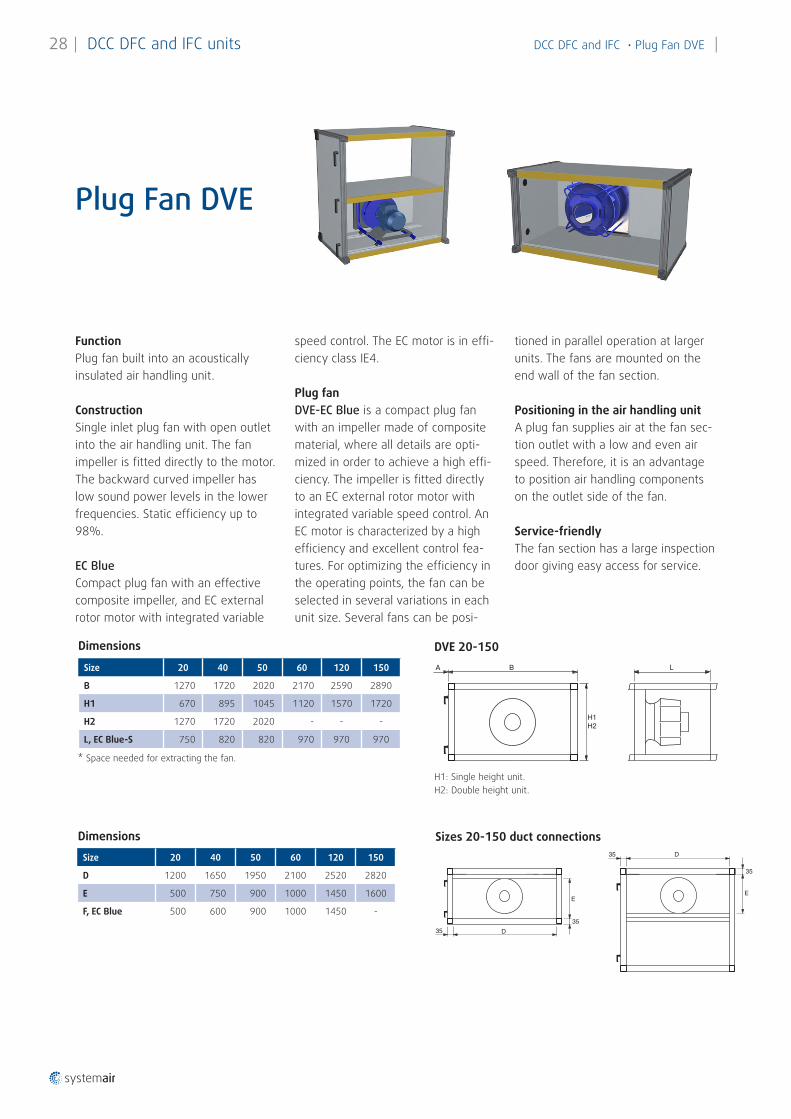
FunctionPlug fan built into an acoustically insulated air handling unit.
ConstructionSingle inlet plug fan with open outlet into the air handling unit. The fan impeller is fitted directly to the motor. The backward curved impeller has low sound power levels in the lower frequencies. Static efficiency up to 98%.
EC Blue Compact plug fan with an effective composite impeller, and EC external rotor motor with integrated variable
speed control. The EC motor is in effi-ciency class IE4.
Plug fanDVE-EC Blue is a compact plug fan with an impeller made of composite material, where all details are opti-mized in order to achieve a high effi-ciency. The impeller is fitted directly to an EC external rotor motor with integrated variable speed control. An EC motor is characterized by a high efficiency and excellent control fea-tures. For optimizing the efficiency in the operating points, the fan can be selected in several variations in each unit size. Several fans can be posi-
tioned in parallel operation at larger units. The fans are mounted on the end wall of the fan section.
Positioning in the air handling unit A plug fan supplies air at the fan sec-tion outlet with a low and even air speed. Therefore, it is an advantage to position air handling components on the outlet side of the fan.
Service-friendlyThe fan section has a large inspection door giving easy access for service.
H1: Single height unit. H2: Double height unit.
DVE 20-150Dimensions
* Space needed for extracting the fan.
Sizes 20-150 duct connections
Size 20 40 50 60 120 150
B 1270 1720 2020 2170 2590 2890
H1 670 895 1045 1120 1570 1720
H2 1270 1720 2020 - - -
L, EC Blue-S 750 820 820 970 970 970
Dimensions
Size 20 40 50 60 120 150
D 1200 1650 1950 2100 2520 2820
E 500 750 900 1000 1450 1600
F, EC Blue 500 600 900 1000 1450 -
| DCC DFC and IFC units28 DCC DFC and IFC • Plug Fan DVE |
Sound Attenuator
29 DCC DFC and IFC units | | DCC DFC and IFC • Sound Attenuator DVD
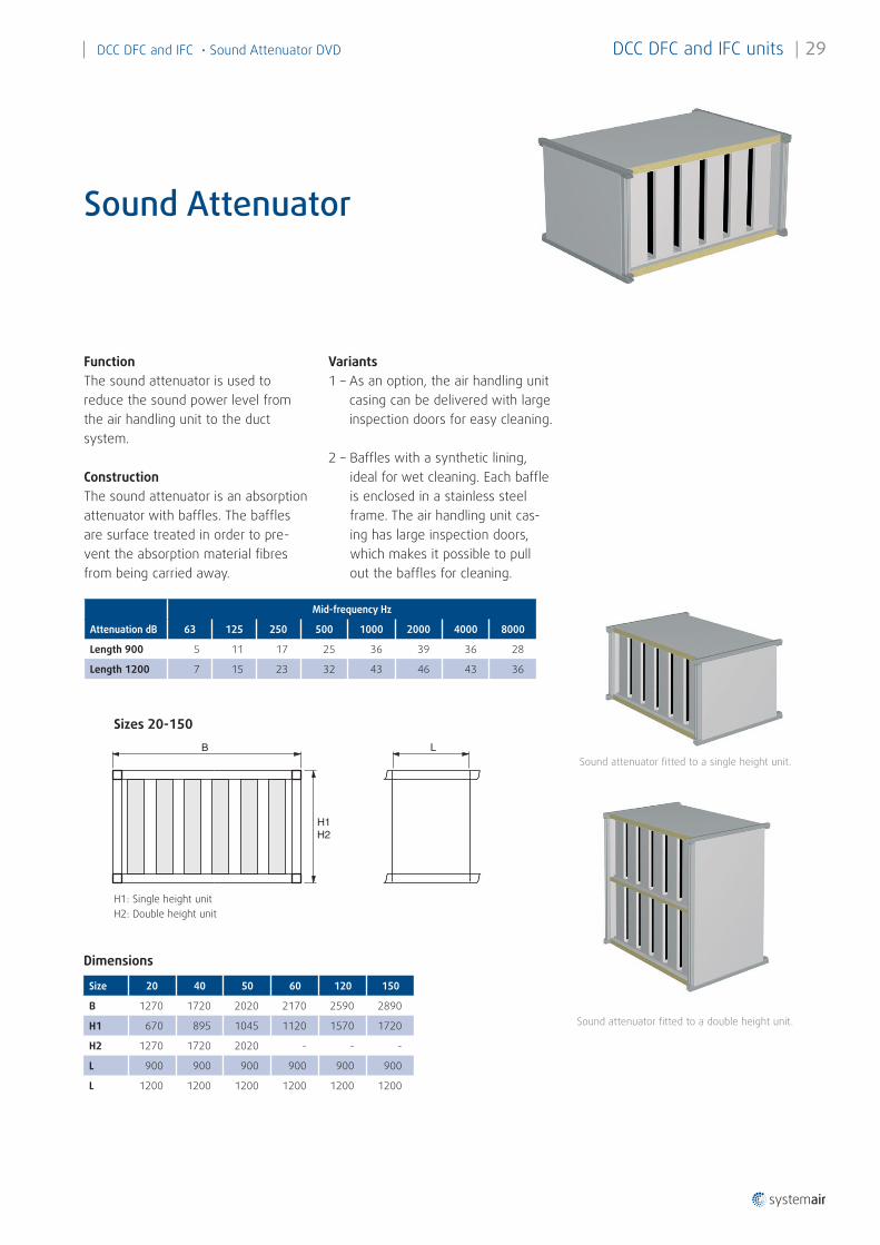
Function The sound attenuator is used to reduce the sound power level from the air handling unit to the duct system.
ConstructionThe sound attenuator is an absorption attenuator with baffles. The baffles are surface treated in order to pre-vent the absorption material fibres from being carried away.
Variants1 – As an option, the air handling unit
casing can be delivered with large inspection doors for easy cleaning.
2 – Baffles with a synthetic lining, ideal for wet cleaning. Each baffle is enclosed in a stainless steel frame. The air handling unit cas-ing has large inspection doors, which makes it possible to pull out the baffles for cleaning.
Mid-frequency Hz
Attenuation dB 63 125 250 500 1000 2000 4000 8000
Length 900 5 11 17 25 36 39 36 28
Length 1200 7 15 23 32 43 46 43 36
H1: Single height unitH2: Double height unit
Sound attenuator fitted to a double height unit.
Sound attenuator fitted to a single height unit.
Sizes 20-150
Dimensions
Size 20 40 50 60 120 150
B 1270 1720 2020 2170 2590 2890
H1 670 895 1045 1120 1570 1720
H2 1270 1720 2020 - - -
L 900 900 900 900 900 900
L 1200 1200 1200 1200 1200 1200
Inspection Section
Empty Section
| DCC DFC and IFC units30 DCC DFC and IFC • Sound Attenuator DVD |
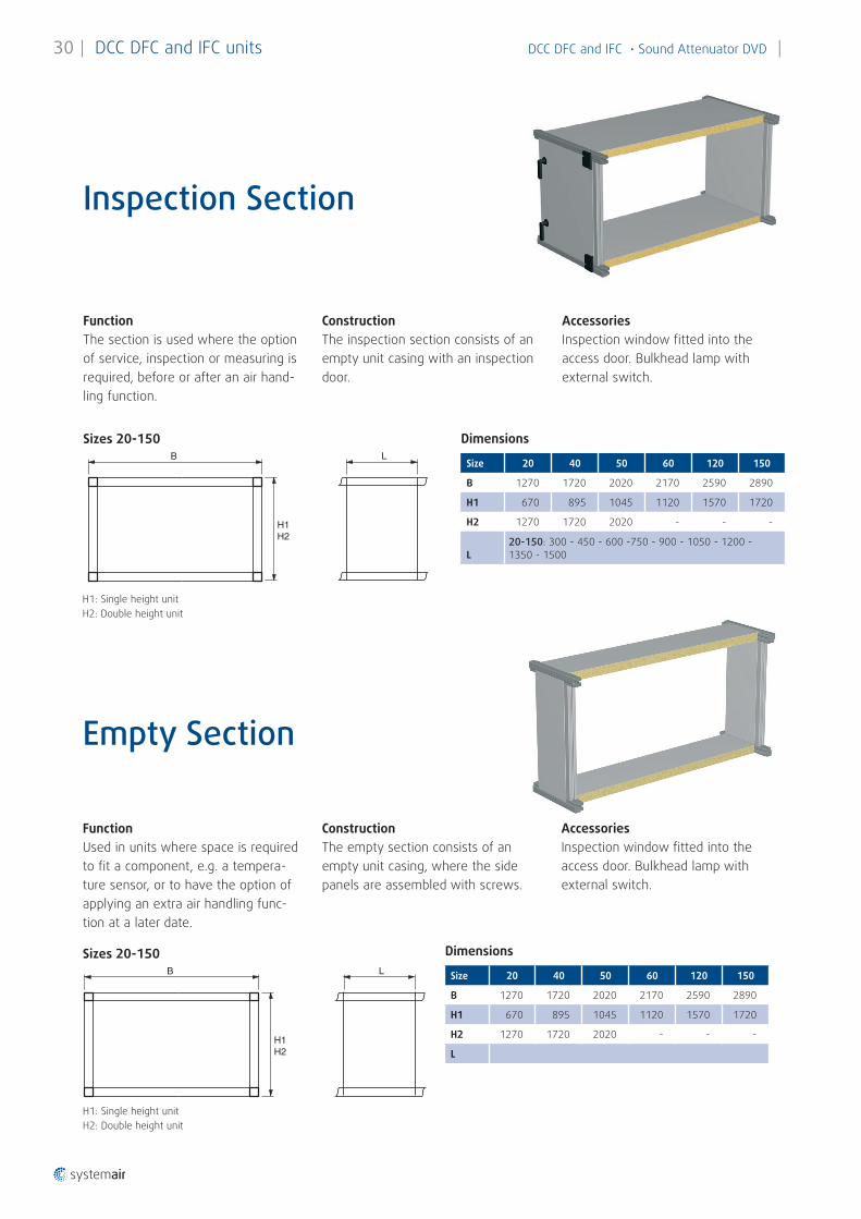
Function The section is used where the option of service, inspection or measuring is required, before or after an air hand-ling function.
H1: Single height unitH2: Double height unit
Sizes 20-150
ConstructionThe inspection section consists of an empty unit casing with an inspection door.
AccessoriesInspection window fitted into the access door. Bulkhead lamp with external switch.
Dimensions
Size 20 40 50 60 120 150
B 1270 1720 2020 2170 2590 2890
H1 670 895 1045 1120 1570 1720
H2 1270 1720 2020 - - -
L20-150: 300 - 450 - 600 -750 - 900 - 1050 - 1200 - 1350 - 1500
H1: Single height unitH2: Double height unit
FunctionUsed in units where space is required to fit a component, e.g. a tempera-ture sensor, or to have the option of applying an extra air handling func-tion at a later date.
Sizes 20-150 Dimensions
Size 20 40 50 60 120 150
B 1270 1720 2020 2170 2590 2890
H1 670 895 1045 1120 1570 1720
H2 1270 1720 2020 - - -
L
ConstructionThe empty section consists of an empty unit casing, where the side panels are assembled with screws.
AccessoriesInspection window fitted into the access door. Bulkhead lamp with external switch.
Outdoor Air Section
31 DCC DFC and IFC units | | DCC DFC and IFC • Outdoor Air Section DVY
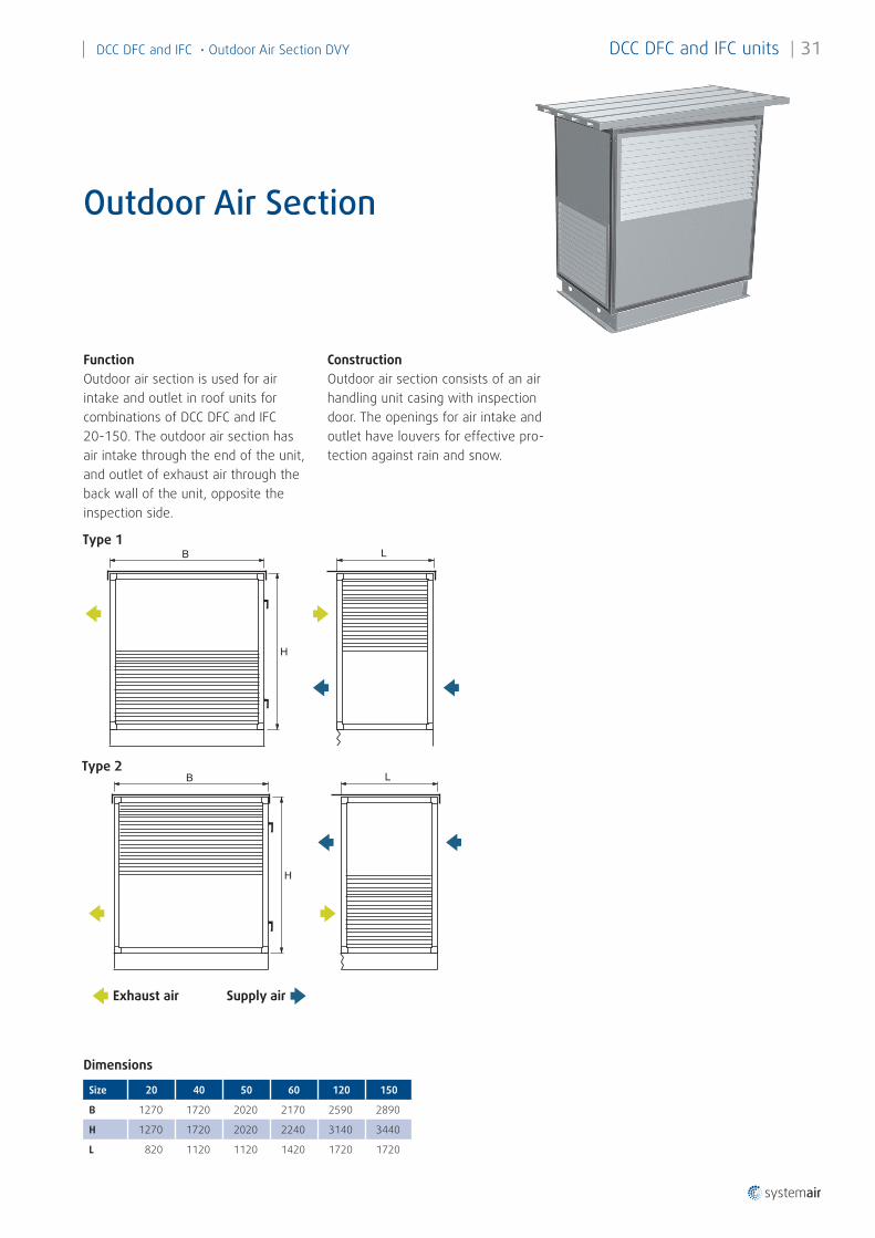
FunctionOutdoor air section is used for air intake and outlet in roof units for combinations of DCC DFC and IFC 20-150. The outdoor air section has air intake through the end of the unit, and outlet of exhaust air through the back wall of the unit, opposite the inspection side.
ConstructionOutdoor air section consists of an air handling unit casing with inspection door. The openings for air intake and outlet have louvers for effective pro-tection against rain and snow.
Dimensions
Size 20 40 50 60 120 150
B 1270 1720 2020 2170 2590 2890
H 1270 1720 2020 2240 3140 3440
L 820 1120 1120 1420 1720 1720
Type 1
Type 2
Exhaust air Supply air
| DCC DFC and IFC units32 DCC DFC and IFC • Supporting Legs • Base Frame DVZ |
Base Frame DVZ
L
B
FunctionUnits in sizes 20-150 for indoor installation can be supplied with base frame in height 150 mm or 250 mm, and have feet which are adjustable from 30-55 mm. Units in sizes 20-150 for outdoor installation are always supplied with 250 mm base frame. Minimum length of base frame is 740 mm. Maximum length of base frame is 6200 mm. Units which are longer, are supplied divided on two or more base frames. Base frame is self-supporting, but as a minimum it must be supported on the longitudinal profiles for each
1500 mm. Inserted, longitudinal pro-files on units in sizes 50-150 do not require support.
ConstructionThe base frame consists of strong, galvanized steel profiles, in either 150 mm or 250 mm height assem-bled with bolts. For indoor installation feet are supplied, which are adjusta-ble from 30-55 mm. As extra protec-tion against corrosion 250 mm base frames for outdoor installation can be supplied hot dip galvanized.
Dimensions
B L
Unit width Unit length
H
Indoor unit 150 og 250
Roof unit 250
Supporting Legs
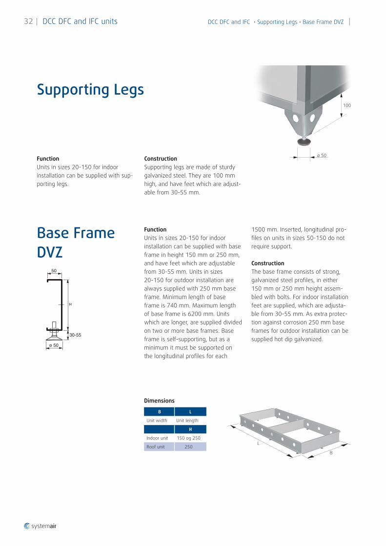
FunctionUnits in sizes 20-150 for indoor installation can be supplied with sup-porting legs.
Construction Supporting legs are made of sturdy galvanized steel. They are 100 mm high, and have feet which are adjust-able from 30-55 mm.
100
ø 50
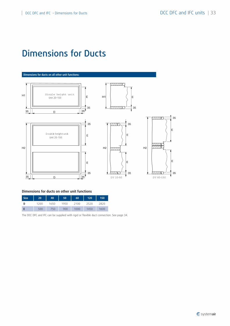
Dimensions for Ducts
33 DCC DFC and IFC units | | DCC DFC and IFC • Dimensions for Ducts
Double height unitDV 10-150
DV 10-50 DV 60-150
Single height unitDV 10-150
Double height unitDV 10-150
DV 10-50 DV 60-150
Single height unitDV 10-150
Dimensions for ducts on other unit functions
Size 20 40 50 60 120 150
D 1200 1650 1950 2100 2520 2820
E 500 750 900 1000 1450 1600
Dimensions for ducts on all other unit functions:
The DCC DFC and IFC can be supplied with rigid or flexible duct connection. See page 34.
Unit 20-150
Unit 20-150
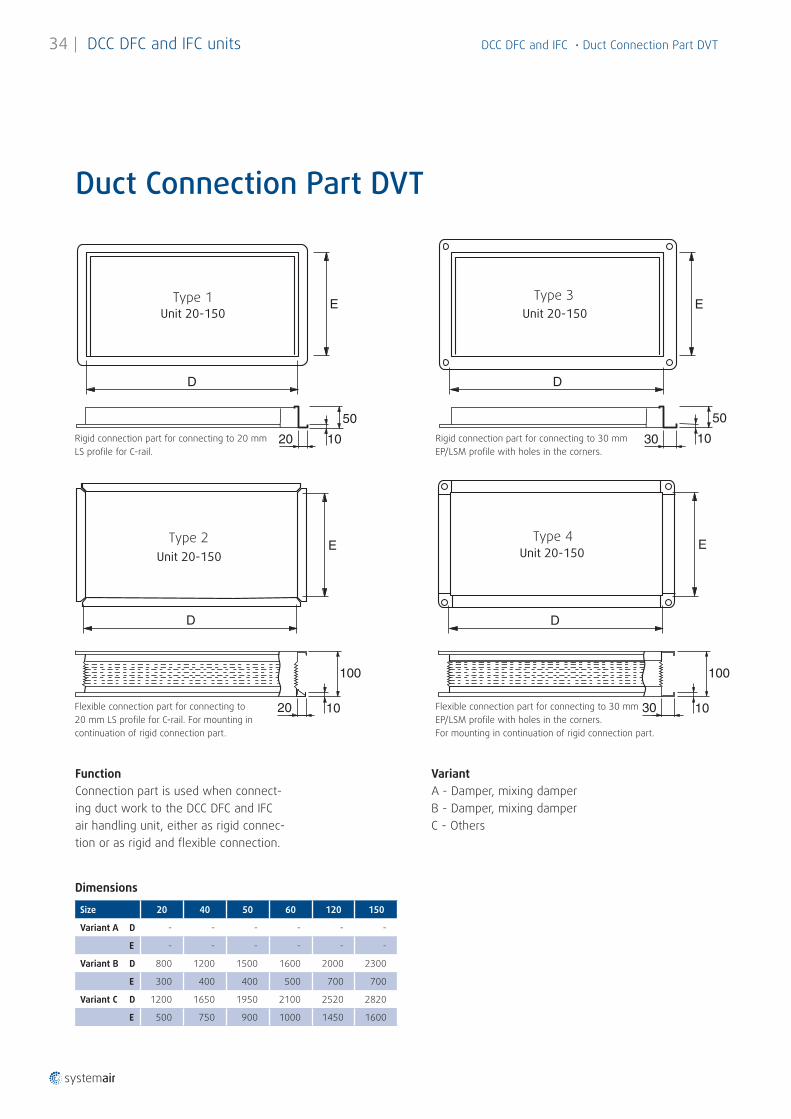
Duct Connection Part DVT
| DCC DFC and IFC units34 DCC DFC and IFC • Duct Connection Part DVT
Type 2DVT 10-150
Type 3DVT 10-240
Type 4DVT 10-240
Rigid connection part for connecting to 20 mm LS profile for C-rail.
Rigid connection part for connecting to 30 mm EP/LSM profile with holes in the corners.
Type 1DVT 10-150
Dimensions
Size 20 40 50 60 120 150
Variant A D - - - - - -
E - - - - - -
Variant B D 800 1200 1500 1600 2000 2300
E 300 400 400 500 700 700
Variant C D 1200 1650 1950 2100 2520 2820
E 500 750 900 1000 1450 1600
FunctionConnection part is used when connect-ing duct work to the DCC DFC and IFC air handling unit, either as rigid connec-tion or as rigid and flexible connection.
Variant A - Damper, mixing damperB - Damper, mixing damperC - Others
Flexible connection part for connecting to 20 mm LS profile for C-rail. For mounting in continuation of rigid connection part.
Flexible connection part for connecting to 30 mm EP/LSM profile with holes in the corners. For mounting in continuation of rigid connection part.
Unit 20-150
Unit 20-150 Unit 20-150
Unit 20-150

35 DCC DFC and IFC units |

Systemair SLU 28942 Fuenlabrada Madrid, Spain
Phone: +34 91 600 29 00,Fax: +34 91 60 70 309
Syst
emai
r ES
• Jun
e 20
16 –
V1