BEHAVIOUR OF REINFORCED CONCRETE TEE- BEAMS...
11
http://www.iaeme.com/IJCIET/index.asp 620 [email protected] International Journal of Civil Engineering and Technology (IJCIET) Volume 8, Issue 11, November 2017, pp. 620–630, Article ID: IJCIET_08_11_065 Available online at http://http://www.iaeme.com/ijciet/issues.asp?JType=IJCIET&VType=8&IType=11 ISSN Print: 0976-6308 and ISSN Online: 0976-6316 © IAEME Publication Scopus Indexed BEHAVIOUR OF REINFORCED CONCRETE TEE- BEAMS RETROFITTED USING FERROCEMENT P. Raghunathapandian Assistant Professor, Dept of Civil Engineering, Meenakshi College of Engineering, K.K Nagar, Chennai, Tamilnadu, India Dr. B. Palani Professor, Dept of Civil & Structural Engineering, Annamalai University, Chidambaram, Tamilnadu, India Dr. D. Elango Professor and Head, Dept of Civil Engineering, Valliammai Engineering College, Kanchipuram (Dt), Tamilnadu, India ABSTRACT Reinforced concrete structural components are found to exhibits distress, even before their service period that is often due to several causes. Such unserviceable structures require immediate attention, enquiry into the cause of distress and suitable remedial measures, so as to bring the structures back to their functional use again. This strengthening and enhancement of the performance of such deficient structural elements in a structure or a structure as a whole is referred to as retrofitting. All the important issue to be addressed in retrofitting is for life safety. Ferrocement is most commonly used as retrofitting material due to their easy availability, economy, durability, and their property of being cast to any shape without needing significant formwork. Ferrocement as a retrofitting material can be pretty useful because it can be applied quickly to the surface of the damaged element without the requirement of any special bonding material and also it requires less skilled labour, as compared to other retrofitting solutions presently existing. The Ferrocement construction has an edge over the conventional reinforced concrete material because of its lighter weight, ease of construction, low self weight, thinner section as compared to RCC and a high tensile strength which makes it a favorable material for prefabrication also. The present investigation on Preloaded Reinforced Concrete Tee Beams is retrofitted using Ferrocement to increase the strength Soffit of Beam and along the side faces of web, by placing the wire mesh along the longitudinal axis of the beam. From the study it is seen that the ultimate load carrying capacity of Reinforced concrete Tee beam elements retrofitted by Ferrocement is significantly increased when Welded Wire mesh are used for retrofitting. Key words: Ferrocement, Retrofitting, Wire Mesh, orientation.
Transcript of BEHAVIOUR OF REINFORCED CONCRETE TEE- BEAMS...

http://www.iaeme.com/IJCIET/index.asp 620 [email protected]
International Journal of Civil Engineering and Technology (IJCIET)
Volume 8, Issue 11, November 2017, pp. 620–630, Article ID: IJCIET_08_11_065
Available online at http://http://www.iaeme.com/ijciet/issues.asp?JType=IJCIET&VType=8&IType=11
ISSN Print: 0976-6308 and ISSN Online: 0976-6316
© IAEME Publication Scopus Indexed
BEHAVIOUR OF REINFORCED CONCRETE
TEE- BEAMS RETROFITTED USING
FERROCEMENT
P. Raghunathapandian
Assistant Professor, Dept of Civil Engineering, Meenakshi College of Engineering,
K.K Nagar, Chennai, Tamilnadu, India
Dr. B. Palani
Professor, Dept of Civil & Structural Engineering,
Annamalai University, Chidambaram, Tamilnadu, India
Dr. D. Elango
Professor and Head, Dept of Civil Engineering,
Valliammai Engineering College, Kanchipuram (Dt), Tamilnadu, India
ABSTRACT
Reinforced concrete structural components are found to exhibits distress, even
before their service period that is often due to several causes. Such unserviceable
structures require immediate attention, enquiry into the cause of distress and suitable
remedial measures, so as to bring the structures back to their functional use again.
This strengthening and enhancement of the performance of such deficient structural
elements in a structure or a structure as a whole is referred to as retrofitting. All the
important issue to be addressed in retrofitting is for life safety. Ferrocement is most
commonly used as retrofitting material due to their easy availability, economy,
durability, and their property of being cast to any shape without needing significant
formwork. Ferrocement as a retrofitting material can be pretty useful because it can
be applied quickly to the surface of the damaged element without the requirement of
any special bonding material and also it requires less skilled labour, as compared to
other retrofitting solutions presently existing. The Ferrocement construction has an
edge over the conventional reinforced concrete material because of its lighter weight,
ease of construction, low self weight, thinner section as compared to RCC and a high
tensile strength which makes it a favorable material for prefabrication also.
The present investigation on Preloaded Reinforced Concrete Tee Beams is
retrofitted using Ferrocement to increase the strength Soffit of Beam and along the
side faces of web, by placing the wire mesh along the longitudinal axis of the beam.
From the study it is seen that the ultimate load carrying capacity of Reinforced
concrete Tee beam elements retrofitted by Ferrocement is significantly increased
when Welded Wire mesh are used for retrofitting.
Key words: Ferrocement, Retrofitting, Wire Mesh, orientation.

P. Raghunathapandian, Dr. B. Palania and Dr. D. Elango
http://www.iaeme.com/IJCIET/index.asp 621 [email protected]
Cite this Article: P. Raghunathapandian, Dr. B. Palania and Dr. D. Elango, Behaviour
of Reinforced Concrete Tee-Beams Retrofitted using Ferrocement. International
Journal of Civil Engineering and Technology, 8(11), 2017, pp. 620–630.
http://www.iaeme.com/IJCIET/issues.asp?JType=IJCIET&VType=8&IType=11
1. INTRODUCTION
Reinforced concrete is one of the most abundantly used construction material, not only in the
developed areas, but also is the remotest places. The Reinforced Cement Concrete structures
constructed in the developed area are often found to exhibit distress and suffer changes, even
before their service period that is often due to several causes such as improper design, faulty
construction, change of usage of the building, change in codal provisions, over loading,
earthquakes, explosion, corrosion, wear and tear, flood, fire etc. such unserviceable structures
require immediate attention and enquiry into cause of distress and suitable remedial measures,
for bringing the structure into its functional use again. In the last few decades several attempts
have been made in India and abroad to study these problems and to increase the life of the
structures by suitable retrofitting and strengthening techniques. Among the plate bonding
techniques FRP plate are quite popular now a days. But it is observed that the use of FRP is
restricted is many developed countries and urban areas of the developing countries due to
higher initial cost and requirement of skilled labour for their application. Thus there is a need
to develop an alternative technique, which is economical and can be executed at site even
with less skilled labour available at site.
2. LITERATURE REVIEW
Many Experimental studies have been conducted in recent year to strengthen flexural
members by using various materials Andrew et.al (1998) studied the flexural performance of
reinforced concrete beams repaired with conventional method and Ferrocement. They
concluded that beams repaired by Ferrocement showed superior performance both at the
service and ultimate load. The flexural strength and ductility of beams repaired with
Ferrocement was reported to be greater than the corresponding original beams and the beams
repaired by the conventional methods. Beams rehabilitated with Ferrocement jackets shows
better performance in terms of ultimate strength, first crack load, crack width, ductility and
rigidity of the section. It was observed that the cracking and ultimate strength increases by
10% and 40% in case of rehabilitated beams, where as these increases were 10 – 30% and 40
– 50% in case of composite section. The jacketing increase the rigidity of the beams and leads
to a reduction in deflection by 37% and a reduction in crack width by 29%.
Kaushik et.al. (1994) studied the addition of thin layer of ferrocement to a concrete beam
and found to be enhancing its ductility and cracking strength Composite beams reinforced
with square mesh exhibit better performance than the composite beams reinforced with
hexagonal mesh. Increasing the number of layers improves the cracking stiffness of the
composite beams in both cases. Nassif et.al. (1998) in this Study ferrocement shell improves
the flexural behavior of RCC beams, however there is no increase in the moment carrying
capacity of under reinforced beams. but, the moment carrying capacity increased by 9% &
15% for balanced and over reinforced section respectively. Seshu et.al. (2000) evaluated the
ultimate strength of the reinforced concrete beams, which failed due to overloading and were
repaired using ferrocement laminate, is affected by the level of damage sustained prior to
repairing. However, ultimate strength, ductility ratio and energy absorption have been
improved after the repair in all cases. The steel ratio used in the repair layer has a great
influence on the amount of gain in the resisting moment, ductility ratio, and energy
absorption. The higher the steel ratio the higher the gain in resisting moment and energy

Behaviour of Reinforced Concrete Tee-Beams Retrofitted using Ferrocement
http://www.iaeme.com/IJCIET/index.asp 622 [email protected]
absorption: conversely, the ductility ratio was found to be decreased with increase in steel
ratio. Fahmy et.al. (1997) studied the flexural behavior of reinforced concrete T-beams
strengthened with thin ferrocement laminate attached to the tension face using L-shaped mild
steel round bars as shear connectors. From the experimental investigation it was concluded
that the performance of the Strengthened beams improved substantially in terms of strength,
flexural rigidity and first crack load, provided the connectors are adequately spaced and the
surface to receive the laminate roughened to ensure sufficient bond strength for composite
action. Paramasivam et.al. (1994) examined the shear transfer between composite layers in
beams. They concluded from this study that full composite action between both layers cannot
be attained based on rough surfaces without shear studs and a minimum of five studs should
be used to ensure full composite action. Shear studs with hooks exhibited better pre cracking
strength compared to all other type of studs. It was also concluded that beam with square
mesh are better than beams with hexagonal mesh for controlling cracks. The addition of
ferrocement laminates to the soffit of the beams delays the first crack load, restrains cracks
from further widening and increases the flexural stiffness and load capacities of the
strengthened beam. The improvement in mid-span deflection and load capacities are lower in
beams where the composite action was lost between the original beam and the strengthening
ferrocement laminates. Thus it is suggested that the surface of the beam to receive the
ferrocement laminate to be roughened and provided with closely spaced shear connectors in
order to ensure full composite action. Jumaaet et.al. Studied that the shear connectors used for
the purpose of strengthening of beam also affects the formation of first crack, mid-span
deflection and also the load capacity of the beam. The improvements in reducing the cracking,
deflection and ultimate load was greater with smaller shear connector spacing. They also
concluded that the performance of the strengthened beam with higher volume fraction of
reinforcement in ferrocement laminates was slightly better than the one with lower volume
fraction results.
3. EXPERIMENTAL PROGRAMME
Table 1 Properties of Materials
Properties of Cement
Sl.no Property Experimental Value Indian Standards
1 Grade 53 IS:12269 - 2013
2 Soundness Test 2mm IS:4031 (Part-3)2005
3 Fineness of Cement 8% IS:4031 (Part-2)2005
4 Consistency of Cement 30% IS:4031(Part-4)2005
5 Initial Setting Time 45mins IS : 12269:2013 Clause 6
6 Final Setting Time 230mins IS : 12269:2013 Clause 6
7 Specific gravity 3.15 IS:4031(Part-3)2005
Compressive strength of cement mortar cubes (N/mm2
)
8 3 Days 29.31 IS : 12269:2013 Clause 6
9 7 Days 38.12 IS : 12269:2013 Clause 6
10 28 Days 54.36 IS : 12269:2013 Clause 6
Properties of Fine Aggregates
11 Fineness modulus 2.9 IS:2386(Part-1)2002
12 Specific Gravity 2.59 IS: 2386 (Part-3)2002
13 Water Absorption 1% IS: 2386 (Part-3)2002
Properties of Coarse Aggregates (10 – 20 mm)

P. Raghunathapandian, Dr. B. Palania and Dr. D. Elango
http://www.iaeme.com/IJCIET/index.asp 623 [email protected]
14 Water Absorption 0.5% IS: 2386(Part-3)2002.
14 Specific Gravity 2.74 IS: 2386(Part-3)2002.
15 Impact test 46.53% IS:2386(Part-4)2002
16 Specific Gravity 2.74 IS: 2386(Part-3)2002.
17 Fineness modulus 8.44 IS: 2386(Part-1)2002
Table 2 Summary of Strengthening Plan
Sl. No Beam
Group Beam Code
Pre – Loading
Level (%)
Type of
Strengthening
Steel Ratio
(%)
Volume fraction of
Ferrocement (%)
1
BC
BC – 1 100
Nil
0.425 1.61
2 BC – 2 100 0.425 1.61
3 BC - 3 100 0.425 1.61
4
BRB
BRB 1- 1
60
At Soffit only 0.425 1.61
5 BRB 1 – 2 At Soffit only 0.425 1.61
6 BRB 1 – 3 At Soffit only 0.425 1.61
7 BRB 2 – 1
70
At Soffit only 0.425 1.61
8 BRB 2 – 2 At Soffit only 0.425 1.61
9 BRB 2 – 3 At Soffit only 0.425 1.61
10 BRB 3 – 1
80
At Soffit only 0.425 1.61
11 BRB3 - 2 At Soffit only 0.425 1.61
12 BRB3 - 3 At Soffit only 0.425 1.61
13
BRS
BRS 1- 1
60
Along the faces of
beam only 0.425 1.61
14 BRS1 – 2 Along the faces of
beam only 0.425 1.61
15 BRS1 – 3 Along the faces of
beam only 0.425 1.61
16 BRS2 – 1
70
Along the faces of
beam only 0.425 1.61
17 BRS2 – 2 Along the faces of
beam only 0.425 1.61
18 BRS2 – 3 Along the faces of
beam only 0.425 1.61
19 BRS3 – 1
80
Along the faces of
beam only 0.425 1.61
20 BRS3 - 2 Along the faces of
beam only 0.425 1.61
21 BRS3 - 3 Along the faces of
beam only 0.425 1.61
To carry out the investigation, Material used and its Properties are tabulated M25 Grade of
concrete mix was used for preparation of specimen and Twenty one Reinforced Concrete Tee
beams are casted. The specimens of reinforced under reinforced, balanced flanged concrete
beam. The specimen consists of flange of size 510*100 mm and web of 150 mm*300 mm
reinforced with conventional steel and the length of the beam is 3000 mm. Main
reinforcements of Tee beams were high yield strength deformed steel bars of 3 numbers of
10mm diameter bars and four number 8mm diameter bars are used for stirrups. Out of these
fourteen beams, three were used as control beams and tested for failure to find out the safe
load carrying capacity and also ultimate load carrying capacity corresponding to the allowable
deflection as per IS 456 - 2007. The cross sectional geometries and longitudinal
reinforcements were the same for all the specimens. Longitudinal reinforcement consist of
three 10 mm diameter steel rebar‟s in the bottom of the beam. Strengthening was not applied
to control beam.
Behaviour of Reinforced Concrete Tee-Beams Retrofitted using Ferrocement
http://www.iaeme.com/IJCIET/index.asp 624 [email protected]
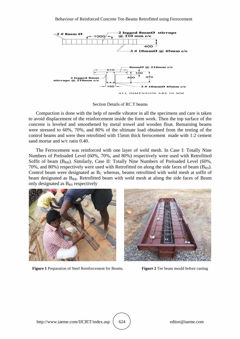
Section Details of RC T beams
Compaction is done with the help of needle vibrator in all the specimens and care is taken
to avoid displacement of the reinforcement inside the form work. Then the top surface of the
concrete is leveled and smoothened by metal trowel and wooden float. Remaining beams
were stressed to 60%, 70%, and 80% of the ultimate load obtained from the testing of the
control beams and were then retrofitted with 15mm thick ferrocement made with 1:2 cement
sand mortar and w/c ratio 0.40.
The Ferrocement was reinforced with one layer of weld mesh. In Case I: Totally Nine
Numbers of Preloaded Level (60%, 70%, and 80%) respectively were used with Retrofitted
Soffit of beam (BRB). Similarly, Case II: Totally Nine Numbers of Preloaded Level (60%,
70%, and 80%) respectively were used with Retrofitted on along the side faces of beam (BRS).
Control beam were designated as BC whereas, beams retrofitted with weld mesh at soffit of
beam designated as BRB. Retrofitted beam with weld mesh at along the side faces of Beam
only designated as BRS respectively
Figure 1 Preparation of Steel Reinforcement for Beams. Figure 2 Tee beam mould before casting

P. Raghunathapandian, Dr. B. Palania and Dr. D. Elango
http://www.iaeme.com/IJCIET/index.asp 625 [email protected]
Figure 3 Pouring of Concrete on Tee Beam Mould Figure 4 Concreting of Tee beam mould
Figure 5 Demoulded RC Tee Beams Figure 6 RC Tee Beams under Curing
All the beams were tested with an effective span of 2.8 m. Two concentrated loads were
applied at 1m spacing from both supports (Fig 6). The beams were tested using hydraulically
operated Jacks connected to a data acquisition system through the load cells with an increase
in load
Figure 7 Schematic Diagram for Testing Arrangement

Behaviour of Reinforced Concrete Tee-Beams Retrofitted using Ferrocement
http://www.iaeme.com/IJCIET/index.asp 626 [email protected]
Figure 8 Flexural Tested on Tee Beam
The deflections in the beams were noted using three dial gauges placed at the quarter span
points. The load is applied almost at a uniform rate load and deflections were recorded at
regular intervals for each step.
4. PROCESS OF RETROFITTING ON PRE LOADED BEAM
The beams were stressed up to a specified limit as above and then retrofitted by applying weld
mesh and then plastering it with cement mortar up to the thickness of 30 mm for all 18 beams.
Effect of three different stress levels of 60%, 70% and 80% has been studied. First of all
surface of beams were cleaned by sand blasting techniques. One layer of weld mesh stretched
and attached to soffit of beams and also alongside faces of beams. The nail and visor used for
bonding between beam and mesh. Then 15mm plaster in the form of 1:2 Cement mortars is
applied on faces of beams. After remolding the beam were subjected to curing for 28days.
Figure 9 Beams are retrofitting at Soffit beam (BRB) Figure 10 Beams are retrofitting alongside faces (BRS)
5. TEST RESULTS AND DISCUSSION
The control beams were tested up to failure. The remaining 18 beams were stressed to various
levels i.e., 60%, 70% and 80% of the average ultimate load of control beams. Subsequently
the retrofitting of beams using orientations of weld mesh in the ferrocement was carried out.
These retrofitted beams were then loaded to failure and the data was recorded in the form of
load and deflection. Fig 11, 12 and 13 shows the load deflection behaviors at the mid span
points of the control as well as beams retrofitted with welded wire mesh orientations. It is
observed from the curves in fig 11, 12 and 13 shows that with an increase in load there is a
considerable increase in deflection for all the beams. It was also noted that the Maximum
P. Raghunathapandian, Dr. B. Palania and Dr. D. Elango
http://www.iaeme.com/IJCIET/index.asp 627 [email protected]
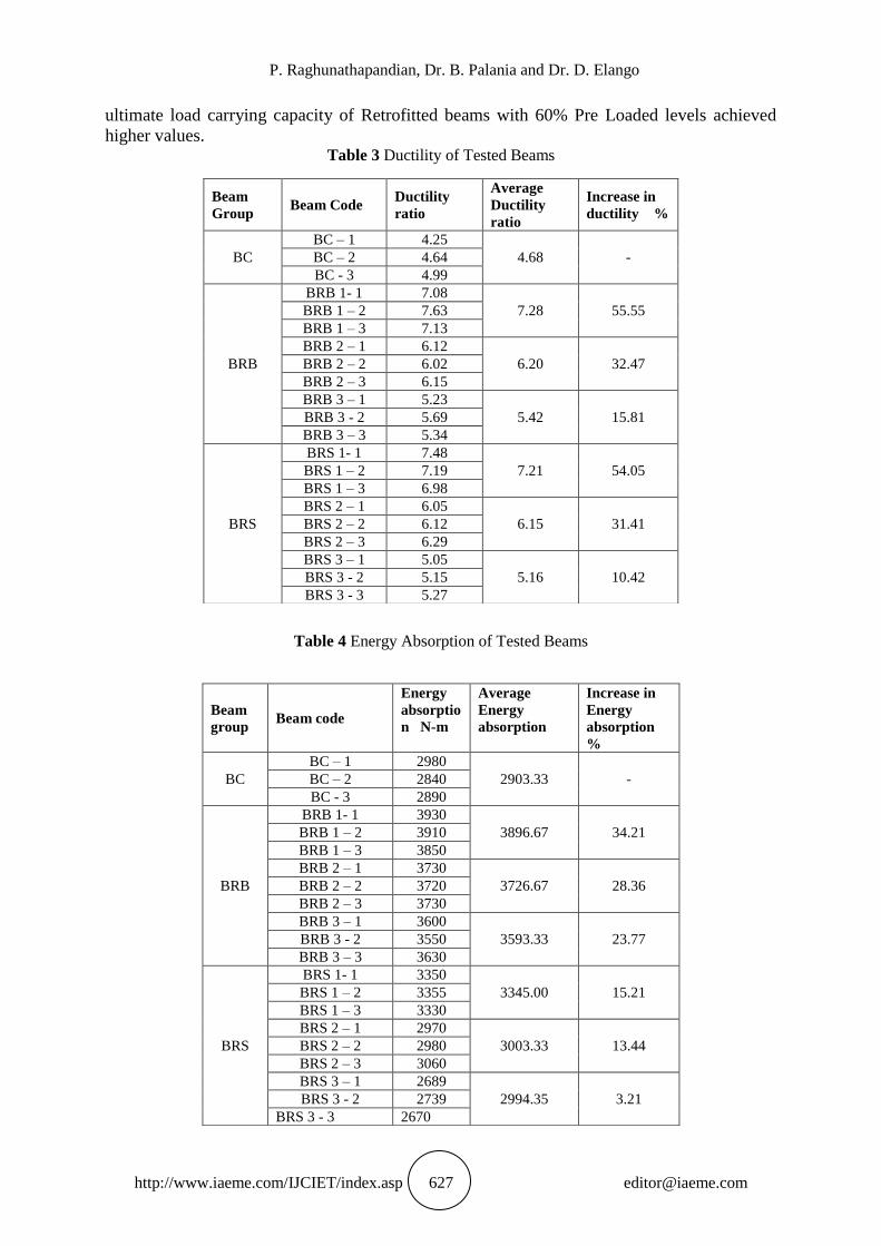
ultimate load carrying capacity of Retrofitted beams with 60% Pre Loaded levels achieved
higher values. Table 3 Ductility of Tested Beams
Table 4 Energy Absorption of Tested Beams
Beam
Group Beam Code
Ductility
ratio
Average
Ductility
ratio
Increase in
ductility %
BC
BC – 1 4.25
4.68 - BC – 2 4.64
BC - 3 4.99
BRB
BRB 1- 1 7.08
7.28 55.55 BRB 1 – 2 7.63
BRB 1 – 3 7.13
BRB 2 – 1 6.12
6.20 32.47 BRB 2 – 2 6.02
BRB 2 – 3 6.15
BRB 3 – 1 5.23
5.42 15.81 BRB 3 - 2 5.69
BRB 3 – 3 5.34
BRS
BRS 1- 1 7.48
7.21 54.05 BRS 1 – 2 7.19
BRS 1 – 3 6.98
BRS 2 – 1 6.05
6.15 31.41 BRS 2 – 2 6.12
BRS 2 – 3 6.29
BRS 3 – 1 5.05
5.16 10.42 BRS 3 - 2 5.15
BRS 3 - 3 5.27
Beam
group Beam code
Energy
absorptio
n N-m
Average
Energy
absorption
Increase in
Energy
absorption
%
BC
BC – 1 2980
2903.33 - BC – 2 2840
BC - 3 2890
BRB
BRB 1- 1 3930
3896.67 34.21 BRB 1 – 2 3910
BRB 1 – 3 3850
BRB 2 – 1 3730
3726.67 28.36 BRB 2 – 2 3720
BRB 2 – 3 3730
BRB 3 – 1 3600
3593.33 23.77 BRB 3 - 2 3550
BRB 3 – 3 3630
BRS
BRS 1- 1 3350
3345.00 15.21 BRS 1 – 2 3355
BRS 1 – 3 3330
BRS 2 – 1 2970
3003.33 13.44 BRS 2 – 2 2980
BRS 2 – 3 3060
BRS 3 – 1 2689
2994.35 3.21 BRS 3 - 2 2739
BRS 3 - 3 2670

Behaviour of Reinforced Concrete Tee-Beams Retrofitted using Ferrocement
http://www.iaeme.com/IJCIET/index.asp 628 [email protected]
Figure 11 Load – Deflection Relationships of CB, BRB, and BRS on 60% Pre-loaded Beams.
Figure 12 Load – Deflection Relationships of CB, BRB, and BRS on 70% Pre-loaded Beams.
Figure 13 Load – Deflection Relationships of CB, BRB, and BRS on 80% Pre-loaded Beams.
6. CONCLUSIONS
Based upon the test results of the experimental study undertaken, the following conclusions
were drawn:
The failure of the composite is characterized by development of flexural cracks over the
tension zone.

P. Raghunathapandian, Dr. B. Palania and Dr. D. Elango
http://www.iaeme.com/IJCIET/index.asp 629 [email protected]
All the beams retrofitted using ferrocement exhibit higher flexural strength when compared
with control beams.
Beams pre-loaded up to 60% of their ultimate load and retrofitted using ferrocement achieved
higher ultimate load levels when compared with beams pre-loaded up to 70% and 80%.
In flexure, the beams retrofitted at bottom of web give more strength when compared to the
beams retrofitted at along the side faces of web Portions.
Beams retrofitted using ferrocement at soffit only, achieved on ultimate load which is 16.57%
higher than that of control beams. Similarly beams retrofitted along the side faces of web
achieved on ultimate load which is 6.35% higher than that of control beams.
All the retrofitted beams showed significant increase in ductility ratio and considerable
increase in energy absorption.
REFERENCES
[1] ACI committee 549 (1982), „State of the art report on ferrocement‟, concrete international
4.
[2] ACI committee 549 (1993) guide for the design, construction, (reapproved 1999) and
repair of ferrocement.
[3] American concrete institute (1979), „Ferrocement materials and applications‟ pub pp-61.
[4] Ambily P.S., Madheswaran C.K., Lakhsmanan.N., Dattatreya J.K., Jaffer Sathik S.A
(2012), „Experimental studies on Shear behaviour of reinforced Geopolymer concrete thin
webbed T-beams with and without fibres‟, International journal of civil and structural
engineering, Volume 3, No 1, ISSN : 0976 – 4399.
[5] Arjan Fakhraldin Abdullah., Mazin Burhan Adeen., Alya'a Abbas Al-Attar (2014),
“Studying Flexural Behavior of Reinforced Fibrous Self- Compacted Concrete T- Beams
Strengthened with CFRP SHEETS”, International Journal of Innovative Technology and
Exploring Engineering, Volume 3, Issue-8.
[6] Bhuvaneswari.P and DR. B.Palani,(2017) “Flexural Behaviour of Ferrocement Palnels
with Slica Fume and China Clay AS Cement Replacement Materials”, International
Journal of Advances in Engineering Research, vol no 13 isuuse no V.
[7] Bong J.H.L and Ahmed E (2010), „Study the structural behaviour of ferrocement beam‟,
UNIMAS e- journal of civil engineering, Vol. 1(2).
[8] IS: 10262-2009, „Indian standard concrete mix proportioning guidelines‟ (first revision),
Bureau of Indian standards, new Delhi.
[9] IS: 12269-2013, „Indian standard specification for 53 grade ordinary Portland cement‟
(first reprint 1993), Bureau of Indian standards, New Delhi.
[10] Kaushik S.K. and Dubey A.K. “Performance evaluation of RC Ferrocement Composite
Beams” Proceedings of Fifth International Symposium, UMIST, pp 240-256, 1994.
[11] Karthick J., Dr. K.Natarajan (2014), „Cyclic Load Behaviour of RC T - Beams internally
Reinforced with GFRP Reinforcements‟, International Journal of Advanced Research in
Education Technology, Vol. 1, Issue 1.
[12] Khan S.U., Rafeeqi S.F.A. and Ayub T. (2013), „Strengthening of RC beams in flexure
using ferrocement‟, International Journal of Science & Technology , Transactions of civil
engineering, Vol. 37, No. c+, pp 353-365.
[13] Ladi Y V and Mohite P M (2013), „Experimental evaluation of reinforced concrete beam
retrofitted with ferrocement‟, International journal of research in engineering and
technology, Vol. 2, No. 3.

Behaviour of Reinforced Concrete Tee-Beams Retrofitted using Ferrocement
http://www.iaeme.com/IJCIET/index.asp 630 [email protected]
[14] Nassif, Hani H and Najm, Husan, “Experimental and analytical Investigation of
Ferrocement Concrete Composite” Cement and Concrete Composite, Vol 26, pp 787-
796,2004.
[15] Palani. B and Bhuvaneswari.P (2017), “An experimental study on flexural behavior of
ferrocement panels with silica fume as an admixture and replacement for cement”,
International Journal of Civil Engineering and Technology (IJCIET), Volume 8, Issue 6,
June 2017, pp. 349–359.
[16] Paramasivam. P, Omg, K.C.G and Lim C.T.E., “Ferrocement Laminate for Strengthening
of RC T-Beam” Cement and Concrete Composite, Vol 16, pp 143-152, 1994.
[17] Videvelli. B, Antiny Jeyasehar, and Srividhya P.R, “Repair and Rehabiatation of
reinforced concrete beams by ferrocement” 7th international Symposium on Ferrocement
and Thin Reinforced Cement Composite, National University of Singapore, 27-29, pp 465-
471, 2001
[18] G. Arunkarthik and S. Sivakamasundari , Exp erimental Study on Flexural Behaviour of
Reinforced Concrete Beam Using Magnatic Water . International Journal of Civil
Engineering and Technology , 8(4), 2017, pp. 518 –525.
[19] Dharane Sidramappa Shivashaankar, Patil Raobahdur Yashwant.Role Of Ferrocement
Cavity Wall In Earthquake Resistant Structure And Construction Method. International
Journal of Advanced Research in Engineering and Technology (IJARET), 5 (6), 2014, pp.
108–111