FERROCEMENT UTILISATION FOR …old.utcluj.ro/download/doctorat/ferrocement utilisation...
10
FERROCEMENT UTILISATION FOR REHABILITATION OF BUILDINGS Abstract of the Phd Thesis Cap.1 INTRODUCTION Fig.1.1 Component elements of the ferrocement 1.1. Definition of the ferrocement The Committee 549 of the American Institute for Concrete [1] submitted the following definition of the ferrocement , subsequently adopted by the majority of the specialists: "The ferrocement is a type of reinforced concrete in thin elements, currently constituted by micro-concrete of hydraulic cement, reinforced with thick layers of continuous netting, in wire, with a relatively small diameter. The net may be metallic or in other materials ". A.E.Naaman [6], defines ferrocement as reinforced concrete in guise of thin elements with very high performance as regards the resistance to extension, the ductility, the resistance to impact. The same author enhances the possibility of using this material for executing several constructions with thin walls, with superior physico-mechanical characteristics. The ferrocement displays a series of advantages as compared to reinforced concrete, among whom: a wider range of elasticity, greater resistance to extension, better behaviour at dynamic stress, increased value of the breaking effort out of extension, 1.2. Evolution in time of the concept of ferrocement The ferrocement is connected to the apparition of the reinforced concrete. The French gardener Joseph Monier used, in 1849, nettings in wire in order to carry out flower vessels in mortar. In 1852, Joseph Luis Lambot obtains a patent for a new material that he denominates "fer- cement" used for the famous boats type ,,Lambot’’. The great achievements pertaining to professor Nervi are in connection with the use of the ferrocement for carrying out the self-supporting shuttering under the shape of very thin folded waves (ex. The roof of the Pavilion for Exhibitions in Torino (fig.1.2.1), destroyed during the war. In 1977 there was set up Committee 549, in view of analyzing the current situation in the field of the research, of the design and of the use of the ferrocement and of drawing up a code for design and execution. Fig.1.2 Roof of the Pavilion for Exhibitions in Torino Fig.1.3 Building of the Opera in Sydney
Transcript of FERROCEMENT UTILISATION FOR …old.utcluj.ro/download/doctorat/ferrocement utilisation...

FERROCEMENT UTILISATION FOR REHABILITATION OF BUILDINGS
Abstract of the Phd Thesis
Cap.1 INTRODUCTION
Fig.1.1 Component elements of the
ferrocement
1.1. Definition of the ferrocement The Committee 549 of the American Institute for Concrete [1]
submitted the following definition of the ferrocement ,
subsequently adopted by the majority of the specialists: "The
ferrocement is a type of reinforced concrete in thin elements,
currently constituted by micro-concrete of hydraulic cement,
reinforced with thick layers of continuous netting, in wire,
with a relatively small diameter. The net may be metallic or
in other materials ". A.E.Naaman [6], defines ferrocement as reinforced concrete in
guise of thin elements with very high performance as regards
the resistance to extension, the ductility, the resistance to impact. The same author enhances the possibility of using this
material for executing several constructions with thin walls, with
superior physico-mechanical characteristics.
The ferrocement displays a series of advantages as compared to
reinforced concrete, among whom:
� a wider range of elasticity,
� greater resistance to extension,
� better behaviour at dynamic stress,
� increased value of the breaking effort out of extension,
1.2. Evolution in time of the concept of ferrocement The ferrocement is connected to the apparition of the reinforced concrete. The French
gardener Joseph Monier used, in 1849, nettings in wire in order to carry out flower vessels in mortar.
In 1852, Joseph Luis Lambot obtains a patent for a new material that he denominates "fer-
cement" used for the famous boats type ,,Lambot’’.
The great achievements pertaining to professor Nervi are in connection with the use of the
ferrocement for carrying out the self-supporting shuttering under the shape of very thin folded
waves (ex. The roof of the Pavilion for Exhibitions in Torino (fig.1.2.1), destroyed during the
war. In 1977 there was set up Committee 549, in view of analyzing the current situation in the
field of the research, of the design and of the use of the ferrocement and of drawing up a code for
design and execution.
Fig.1.2 Roof of the Pavilion for Exhibitions in Torino
Fig.1.3 Building of the Opera in Sydney
1.3. Objective of the doctoral thesis The current doctoral thesis aims at substantiating a procedure for rehabilitating the structural
walls in the brick work, resorting to ferrocement.
Cap.2 STAGE OF ACQUAINTANCE AND USE OF THE FERROCEMENT ABROAD
AND IN ROMANIA
2.1. Elements and constructions in ferrocement abroad
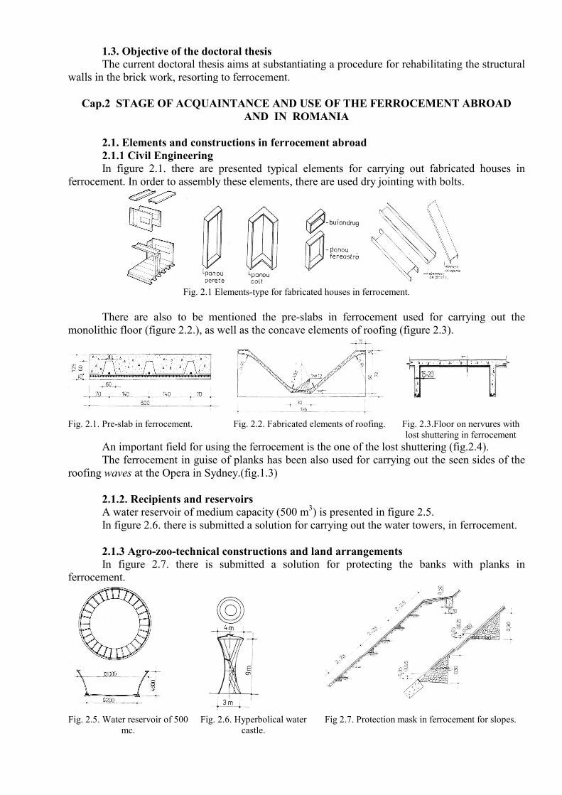
2.1.1 Civil Engineering In figure 2.1. there are presented typical elements for carrying out fabricated houses in
ferrocement. In order to assembly these elements, there are used dry jointing with bolts.
Fig. 2.1 Elements-type for fabricated houses in ferrocement.
There are also to be mentioned the pre-slabs in ferrocement used for carrying out the
monolithic floor (figure 2.2.), as well as the concave elements of roofing (figure 2.3).
Fig. 2.1. Pre-slab in ferrocement.
Fig. 2.2. Fabricated elements of roofing. Fig. 2.3.Floor on nervures with
lost shuttering in ferrocement
An important field for using the ferrocement is the one of the lost shuttering (fig.2.4).
The ferrocement in guise of planks has been also used for carrying out the seen sides of the
roofing waves at the Opera in Sydney.(fig.1.3)
2.1.2. Recipients and reservoirs A water reservoir of medium capacity (500 m
3) is presented in figure 2.5.
In figure 2.6. there is submitted a solution for carrying out the water towers, in ferrocement.
2.1.3 Agro-zoo-technical constructions and land arrangements In figure 2.7. there is submitted a solution for protecting the banks with planks in
ferrocement.
Fig. 2.5. Water reservoir of 500
mc.
Fig. 2.6. Hyperbolical water
castle.
Fig 2.7. Protection mask in ferrocement for slopes.

2.2. Elements and constructions in ferrocement in Romania
2.2.1. Pre-slabs for floor In the framework of the research program carried out at the Faculty of Civil Engineering in
Cluj-Napoca [5], there was carried out during the year 1989 a comparative study with respect to the
behaviour of the pre-slabs in ferrocement and of those in regular reinforced concrete, there being
known the advantages of the use of pre-slabs in realizing the floors.
The comparative analysis of the distress state, of the deformation state, of the resistance state,
proved that the pre-slab in ferrocement has a better behaviour than the pre-slab in reinforced
concrete.
2.2.2. Folded elements in ferrocement Making up through their shape for the
much reduced thickness of the section, the
folded elements are recommended for the
surface sub-assemblies, whatever their use
should be, or as lost shuttering.
Fig. 2.8. Element V I. Plan shuttering
Cap.3. MECHANICAL-PHYSICAL CHARACTERISTICS OF THE FERROCEMENT
3.1. Materials 3.1.1. Matrix ( micro-concrete ) used in
order to carry out the ferrocement consists in a
mixture of hydrated cement, water, fine aggregates
of the diameter of up to 7 mm and admixtures. The minim dosage of cement is of 300 kg/m
3.
3.1.6 Diagram σ-e
The diagram σ-e for the micro-concrete is
similar to the diagram stipulated in STAS
10.107 / 0 - 90 for the concrete (figure 3.1).
Fig. 3.1 Diagram σ-ε idealized for ferrocement at
extension and compression 3.2. Reinforcements
The reinforcement consists in thin wire nettings of 0,5 ... 1,2 mm diameter. Sometimes, in
order to reinforce elements of ferrocement there may be additionally used reinforcement bars (OB
37, PC 52 or STNB ) with a diameter of 4 ... 10 mm, which will be assembled as a framework upon
which there are fastened the wire nettings.
The most used wire nettings have square, rectangular, hexagonal or rhombic meshes ( fig.
3.2 )
Fig. 3.2 – Systems of wire nettings for reinforcing the elements in ferrocement
Cap.4 CALCULATION AND ACHIEVEMENT OF THE ELEMENTS OF
CONSTRUCTIONS IN FERROCEMENT
4.1. Criteria and methods of design Under normal conditions of exploitation, the ferrocement may be deemed a quasi-
homogeneous and elastic material.

4.2. Calculation in the limit state of resistance
4.2.1. Centric extension The calculation of the resistance to centric extension in the fissured stage may be carried out
through taking into consideration only the contribution of the reinforcement oriented after the
direction of the force:
Nt = Arfs , where :
Nt – is the force of extension to the breakage in the considered direction, - fs – resistance of
calculation of the wire
4.2.2. Centric compression The calculation is based on determining the carrying capacity of the matrix to the
compression, there being considered a uniform distribution of the unitary efforts of compression of
the value of 0, 85 fc.
The effect of the flexure may be taken into consideration as in the case of the compressed sections
of reinforced concrete.
4.2.3. Calculation of the flexed elements in normal sections The analysis of the elements of ferrocement subject to flexion is similar to the analysis of the
"girders or of the poles of reinforced concrete with several levels of the reinforcements”. The
calculation of the flexing moment that-1 may take over a section of ferrocement reinforced with n
lines of nettings may be done by taking into consideration the distribution of the efforts as in fig.4.1.
Fig. 4.1 – Distribution of the deformations and of the unitary efforts in a section of ferrocement flexed,
at the breakage
4.2.4. Calculation of the flexed elements in bent sections The resistance to shearing of the ferrocement is due to the contribution of the matrix and of
the reinforcement fibres in the considered section and may be expressed this way:
τc = tm • Vm + ΣFi, • (1 - Fi2 )
1/2σsl .Vfi
where : - xc, xm – the medium unitary efforts of shearing in the composite, respectively in the matrix,
- Fi- cosines of the angle between the fibre i and the direction of the loading.
4.2.5. Verification in the limit states of the normal exploitation
4.2.5.1 Limit cracking state a. Maximum opening of the fissures in the case of the extended elements of ferrocement,
will be determined according to the type of netting this way:
- for nettings in which fs < 345 Srl Wk, max = rE
35000
- for nettings in which fs > 345 Srl Wk.max= rE
20[175 + 3,69 (fs-345Srl)]
b. Maximum opening of the fissures in the case of the flexed elements may be determined
with the relation :
Wkmax ≈ εs·s ·β= fs/Er·s·β , in which :
β – stands for the ratio between the distance to the neuter axis of the extreme extended fibre
and of the extreme line of reinforcement.
Er – modulus of elasticity of the netting system.

c. Limitation of the opening of the fissures
The opening of the fissures in the exploitation will be under 0,10 mm under exploitation
conditions in non-corrosive environment and of 0,05 mm under conditions of corrosive
environment, in the case of the reservoirs of liquids or gases.
4.2.7. Limit state of deformations As the ferrocement is a very flexible material, its design will be done according to other
criteria than those of camber. The limitation of the camber will be carried out as for elements of
regular reinforced concrete.
The calculation of the camber of the flexed elements may be done with the relation:
a = s ·Φ ·L2
s – is a parameter depending on the type and the manner of propping of the element,
Φ –the curvature in the non-fissured stage (0 < Φ < Φ CR) or in the fissured stage (Φ cr ≤Φ ≤Φ y),
L – opening of the element.
4.2.8 Fatigue stresses For the ferrocement structures strained at a number of cycles equal to 2 • 10
6 , the unitary
effort in the reinforcement, during the exploitation, has to be limited at 200 MPa
4.3. Provisions of constructive composition � The volume percentage of reinforcement Vf, in both directions will be no less than 1.8%.
� The total surface specific to the reinforcement Sr, will be no smaller than 0,08 mm2/mm
3
� There is recommended a minimum of two lines of reinforcement nettings.
� The layer of coverage with micro-concrete recommended for the reinforcement is 2 mm.
CAP.5. ALTERNATIVES FOR REHABILITATING THE STRUCTURES IN BRICKWORK
5.1. General aspects During the rehabilitation of the structural systems in brickwork, there have to be taken into
consideration: the age of the construction, the type of brickwork, the type of the material of junction
among the brickwork stone, the structural system, the type of the foundations.
5.2. Consolidation principles The consolidation of the brickwork structures may be done through a multitude of solutions,
such as:
Remaking the dislocated brickwork, partial concreting through executing concrete holes,
through injecting and caulking the fissures and the breaks, through fastening the fissures with clasps
in hotel, through coating the walls with mortar of cement, through introducing tyrants, resorting to
composite materials reinforced with fibres (CPAF), using ferrocement.
The results obtained following the attempts at compression of the poles, respectively at bending of
the girders, consolidated through coating with ferrocement, are eloquent (fig.5.1 si 5.2). There may
be noticed the rise of ductility, as well as the rise of carrying capacity.
Fig.5.1 Diagram effort-deformation for the pole in concrete coated with ferrocement – influence
upon ductility

Fig.5.2 Diagrams effort-deformation for the girders in concrete coated with ferrocement
Cap.6. DESIGN AND TESTING OF BRICKWORK PANELS CONSOLIDATED WITH
FERROCEMENT In the framework of the present work, I have tried to obtain data and to offer a series of
information in connection with the possibility of using the ferrocement for rehabilitating the
constructions. In this respect, I experimented the solution of consolidation through coating upon
four brickwork panels of 0,24x1,90x1,90m
6.1.Description of the consolidation solution through coating with ferrocement The solution is indicated in the case of the old structures, highly deteriorated, in whom the carrying
capacity of the structural walls is much diminished.
The walls (4 panels) in brickwork upon whom there were carried out the determinations, were tested
during the years 2001-2002 by INCERC Cluj Napoca in order to obtain information with the
purpose of improving the methods of calculation of the structures in brickwork during seismic
actions.
In the framework of the experimental program afferent to this work, we used the walls
in order to verify the consolidation through coating with ferrocement and the correspondence
between the theoretical model of calculation and the experimental one. The models of walls were tested until breaking through cyclical lateral loading in the
presence of a constant vertical loading. For their consolidation, there was used the following
technology:
- there were positioned 2 lines of wire nettings of zinc plated steel with the diameter of 1mm
and meshes of 10 x 10 mm. Out of the attempts at extension carried out on the wire nettings, there
resulted values of the resistance of 310 N/mm2. In order to fasten the nettings, there were used nails
previously positioned;
- there was applied the mortar through injection of concrete in medium thickness of 3,5 cm
taking care that the cover layer should have at least 0,5 cm; the mortar had been prepared according
to the following recipe: cement Pa40 - 500kg/mc, sand 0-3 mm - 1700 kg/mc, water - 250 kg/mc.
Out of the attempts on specimens of this mortar, there ensued values of the resistances at 28 days of
39 N/mm2 and of 7,75 N/mm2 during the extension.
The two layers of ferrocement realized together with the broken brickwork a unitary whole
so rigid, that at lateral forces equal to those that caused the breakage of the non-consolidated panels,
the panel turned round (displayed the tendency to turning over). In order to mobilize the
ferrocement, there was necessary to resort to the blockage of the rotation through the supplementary
introduction of two tyrants in steel bars with Ø = 24 mm, fastened on the border of the consolidated
brickwork panel. In this new situation, there were applied the alternating forces in rising rhythm,
with steps of 40 kN. The yield took place round the value of the lateral force of 460 KN, during the cycle VI, when the foundation crushed.
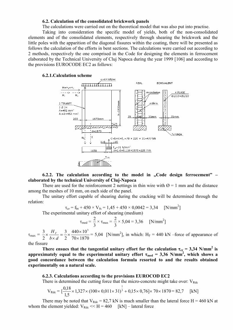
6.2. Calculation of the consolidated brickwork panels The calculations were carried out on the theoretical model that was also put into practise.
Taking into consideration the specific model of yields, both of the non-consolidated
elements and of the consolidated elements, respectively through shearing the brickwork and the
little poles with the apparition of the diagonal fissures within the coating, there will be presented as
follows the calculation of the efforts in bent sections. The calculations were carried out according to
2 methods, respectively the one comprised in the Code for designing the elements in ferrocement
elaborated by the Technical University of Cluj Napoca during the year 1999 [106] and according to
the provisions EUROCODE EC2 as follows:
6.2.1.Calculation scheme
6.2.2. The calculation according to the model in „Code design ferrocement” –
elaborated by the technical University of Cluj-Napoca There are used for the reinforcement 2 nettings in thin wire with Ø = 1 mm and the distance
among the meshes of 10 mm, on each side of the panel.
The unitary effort capable of shearing during the cracking will be determined through the
relation:
τcr = fbt + 450 × Vfx = 1,45 + 450 × 0,0042 = 3,34 [N/mm2]
The experimental unitary effort of shearing (medium)
τmed = 3
2× τmax =
3
2× 5,04 = 3,36 [N/mm
2]
τmax = 187070
10440
2
3
2
3 3
×
××=
××
db
H F = 5,04 [N/mm2], in which: HF = 440 kN –force of appearance of
the fissure
There ensues that the tangential unitary effort for the calculation τcr = 3,34 N/mm2 is
approximately equal to the experimental unitary effort τmed = 3,36 N/mm2, which shows a
good concordance between the calculation formula resorted to and the results obtained
experimentally on a natural scale.
6.2.3. Calculations according to the provisions EUROCOD EC2 There is determined the cutting force that the micro-concrete might take over: VRdc
VRdc = 187070]76,015,0)31011,0100(327,15,1
18,0[ 3
1
×××+×××× = 82,7 [kN]
There may be noted that VRdc = 82,7 kN is much smaller than the lateral force H = 460 kN at
whom the element yielded: VRdc << H = 460 [kN] – lateral force
We determine the maximal lateral force that may be taken over without crushing the micro-
concrete: VRdmax
VRdmax = 11
66,205,01683701
cot +
××××=
+
××××
θθ
υα
tgg
fzb cdwc = 609 [kN]
The maximal cutting force taken over by the maximal reinforcement (reinforcement only with
yokes) VRds is :
VRds = θctgfzS
Aywd
sw ××× = 1270168310
14,3××× = 142684 [N] = 142,7 [kN]
Observations:
- The value VRds = 142,7 kN shows how much can the wire nettings take over of the lateral
force;
The value VRds = 142,7 kN is also confirmed by the experiment in the case of the attempt
without tyrants, when there was obtained a lateral force H = 155 ÷ 159 kN;
- The difference ∆VRds = H – VRds = 460 – 142,7 = 317,3 kN is considered to be taken
over by the 2 tyrants (VT);
VT = AT × fywT = 2 × 452 × 331 ≈ 300.000 N = 300 kN
fyT = 381 N/mm2 – after which effort TER recorded no more (entered into flowing)
- In this hypothesis, the value of the cutting force taken over by the entire reinforcement
(nettings + tyrants) becomes: T
RdsV =VRds + VT = 142,7 + 300 = 442,7 kN ≈ H = 460 kN
- The difference between the calculated value and the value obtained experimentally is:
∆V = 460 – 442,7 = 17,3 kN
- This difference may put on the account of the arbour effect created by the reinforcement
in little poles and calculated with the relation:
Vdorn = N × 4,12 × 33
2
ckwbare fb ××φ = 4 × 4,12 × 33
2
31708 ×× = 14,5 [kN]
There ensues that the lateral total force that the consolidated assembly may take over is:
Vtotal = VRds + VT + Vdorn = 142,7 + 300 + 14,5 = 457,2 kN ≈ H = 460 kN
There may be noted here the concordance between the calculation theoretical model
and the experimental one.
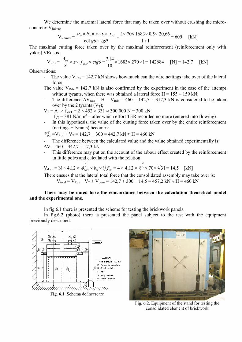
In fig.6.1 there is presented the scheme for testing the brickwork panels.
In fig.6.2 (photo) there is presented the panel subject to the test with the equipment
previously described.
Fig. 6.1. Schema de încercare
Fig. 6.2. Equipment of the stand for testing the
consolidated element of brickwork

Cap.7 CONCLUSIONS. PERSONAL CONTRIBUTIONS
7.1. Conclusions Following the tests on elements and the calculations on the theoretical model presented
above, there may be concluded that whatever should be the calculation method resorted to, the
values of the efforts (or of the breaking forces) are confirmed by those measured on the occasion of
the tests on models on a natural scale.
Beside other consolidation solutions resorting to coating the element, the consolidation
solution with ferrocement submitted and verified by the author of the present work stands for a valid
solution with a good theoretical and experimental support.
7.2.Advantages of the solution The increased resistance to cracking, combined with the facility of its putting into operation,
as well as the relatively low height and low cost make the ferrocement a competitive system for
rehabilitating the structures.
7.3. Personal contributions In the framework of this work, I endeavoured to substantiate a procedure for rehabilitating,
remaking/increasing the capacity of resistance and the structure ductility with brickwork walls
through coating with ferrocement and to submit the most adequate methods of calculation for this
material.
From this point of view, I submitted objective solutions for realizing the coating from the
recipe of micro-concrete, continuing with technology for putting it into operation, and ending with
the calculations with respect to the carrying capacity of the brickwork panels coated with
ferrocement.
In order to formulate such a method, there was necessary for me to go through a vast
bibliography, to analyze it and to synthesize it in a manner that should serve my purpose and at the
same time that should represent a guide for others, too.
The calculations carried out according to the standards, in ferrocement elaborated by the
Technical University of Cluj Napoca, Faculty of Civil Engineering and EUROCOD 2 with respect
to the calculation of the structures in concrete, reinforced concrete and pre-compressed concrete
were confirmed by the results obtained experimentally.
Throughout the elaboration of the present work, I published on the occasion of a few
national and international scientific manifestations, several articles (6 articles) including data
resulted from the documentation realized, from the calculations carried out and from the
experimental results obtained.
I collaborated together with the Team of the Discipline of concrete, reinforced concrete and
pre-compressed concrete of the Faculty of Civil Engineering in Cluj-Napoca during the elaboration
of the project for the rehabilitation of the floors in the sanitary groups afferent to the students’ hostel
nr.8 in Brasov, resorting to ferrocement. Afterwards, I supervised the correct execution of the
designed works and the behaviour in time of the implemented solution, which proved to be a very
good one.
My research continues in the direction of the extension of the use of ferrocement for
rehabilitating the wooden floors. Likewise, I am preoccupied of the use of this material in realizing
the foundations for machines and in their rehabilitation through coating.

BIBLIOGRAPHY
1.*** ACI 549- R -88 - State of the Art Report on Ferrocement jx
2.***ACI 549. IR - JJ8 - Gruide for the Design, Construction and Repair of Ferrocement
3. B.K. Paul, R. Pama - Ferrocement - IFIC, Bangkok Thailand, 1978.
5.*** - Studii şi cercetări privind proprietăŃile ferocimentului şi posibilităŃile de utilizare
a lui în construcŃii - Contract 1103/1989. Beneficiar ICCPDC Bucureşti.
6. A.E.Naaman - Prospect in Ferrocement Materials, Applications and Technology -
Joumal of Ferrocement voi. 15 no. 2 April 1985, pg. 165 - 167
12. T.OneŃ, M.Iancău, L.Szigeti - The Behaviour until Failure of the Ferrocement Folded Members.
Proceedings of the International Conference "Failure of Concrete Structures". Strbske Pleso,
Slovakia, June, 1993.
17. D.Alexander - Views on Present State of Ferrocement - Journal of Ferrocement voi. 23 no. 1
January 1993;
69. M.A.Mansur, P.Paramasivam, 1985. Ferrocement under combined Bending and axial loads.
International Journal of Cement and Lightweight Concrete 7(3): 151-158
105. T. OneŃ, Felicia Flonta: Durabilitatea elementelor de construcŃii din ferociment. ConstrucŃii, 1994, pp 51...«50.
106. T. Onet, C. Magurean, V. Vescan, „Cod de proiectare si executie a elementelor din
ferociment”- Universitatea Tehnica Cluj-Napoca, Contract M.E.N.33830/1999.
112.Marian Iancău . ProprietăŃile de rezistenŃă şi de deformaŃie ale materialelor compozite. Referat
de doctorat. Universitatea Tehnică Cluj-Napoca, oct. 1994.
141.C.Bob, A. Ghersi,A Plumier &C. Trezos: Calculul structurilor din beton, beton armat si beton
precomprimat EUROCODE 2 –exemple de calcul- tempus Phare Complementary Measures Project
01198.
142. Z.Kiss, T Onet-Proiectarea structurilor de beton dupa SREN 1992-1-Ed. ABEL-2008;
148. A. Talposi., G. Muntean – Tehnologia consolidarii constructiilor – Ed. Universitatii Transilvania
Brasov-1999;