BEHAVIOUR OF PIN AND PARTIAL STRENGTH BEAM-TO...
34
BEHAVIOUR OF PIN AND PARTIAL STRENGTH BEAM-TO-COLUMN CONNECTIONS WITH DOUBLE CHANNEL COLD-FORMED STEEL SECTIONS TAN CHER SIANG UNIVERSITI TEKNOLOGI MALAYSIA
Transcript of BEHAVIOUR OF PIN AND PARTIAL STRENGTH BEAM-TO...

BEHAVIOUR OF PIN AND PARTIAL STRENGTH
BEAM-TO-COLUMN CONNECTIONS WITH DOUBLE
CHANNEL COLD-FORMED STEEL SECTIONS
TAN CHER SIANG
UNIVERSITI TEKNOLOGI MALAYSIA

BEHAVIOUR OF PIN AND PARTIAL STRENGTH BEAM-TO-COLUMN
CONNECTIONS WITH DOUBLE CHANNEL COLD-FORMED STEEL
SECTIONS
TAN CHER SIANG
A thesis submitted in fulfilment of the
requirements for the award of the degree of
Doctor of Philosophy (Civil Engineering)
Faculty of Civil Engineering
Universiti Teknologi Malaysia
DECEMBER 2009

iv
ACKNOWLEDGEMENT
The author would like to express his utmost gratitude to his supervisor,
Professor Ir. Dr. MAHMOOD MD TAHIR for his guidance and assistance
throughout the study. The author would also like to acknowledge his colleagues
especially Mr. SHEK POI NGIAN, Mr. WONG KAH LEONG and the structural
laboratory staff team headed by YM RAJA EZAR ISHAMUDDIN ABD LATIF and
Mr. RAZALE BIN MOHAMAD, and all the staff of Faculty of Civil Engineering for
their supports. Special Thanks also goes to Dr. ARIZU BIN SULAIMAN, Dr.
AIRIL YASREEN BIN MOHD YASSIN and SELLYNA ABDUL SHUKOR from
the Steel Technology Centre, Faculty of Civil Engineering for their contributions
towards this research. Last but not least, deepest appreciation to the author’s parents
and friends for their encouragements and full moral supports throughout the progress
of this doctorate study.

v
ABSTRACT
The application of cold-formed steel in light steel framing design can become
a popular choice of Industrialized Building System (IBS), by extending the steelwork
design into residential housing. However there is a lack of in-depth study on the
joints behaviour for primary structures, particularly the beam-to-column connection.
The objectives of this research are to develop the design procedures of bolted beam-
to-column connections for double channel cold-formed steel sections, to study the
pin and partial strength behaviour of the developed connections based on their
strength and stiffness performance, and to validate the performance of the proposed
connection configurations by comparing the analytical calculation to experimental
results. Analytical study was carried out to develop design procedures for five types
of joint methods, namely double angle web-cleats (J1-WC), top-seat flange-cleats
(J2-FC), combined flange-web-cleats (J3-FWC), gusset plates (J4-HG) and
combined gusset plate flange-cleats (J5-HGFC) to form bolted connections to
accommodate members in practical orientations. A series of full scale experimental
investigation comprised of twenty-four isolated joint tests and twelve sub-
assemblage frame tests have been carried out to understand the connections’ strength
and stiffness behaviour. The experimental results showed good agreement compared
to theoretical prediction. From the experimental and analytical results, J1-WC, J2-
FC and J3-FWC connections were classified as pin joints, with the strength less than
25% of beam capacity; while J4-HG and J5-HGFC connections were classified as
partial strength joints with moment resistance of joint in the range of 46% to 96% to
the moment resistance of the connected beam. It was concluded that among the five
types of proposed connections, J1-WC, J2-FC and J3-FWC connections were
designed as pin joint, J4-HG and J5-HGFC connections were validated to be used as
partial strength joints.

vi
ABSTRAK
Penggunaan keluli tergelek sejuk dalam rekabentuk kerangka keluli ringan
boleh menjadi satu pilihan yang popular bagi ’Industralized Building System’ (IBS)
dengan memperluaskan rekabentuk struktur keluli kepada industri perumahan.
Walau bagaimanapun terdapat kekurangan dalam kaji-selidik lanjutan terhadap
kelakuan penyambungan bagi struktur utama, khususnya sambungan rasuk-tiang.
Objektif penyelidikan ini adalah untuk menghasilkan prosidur rekabentuk untuk
sambungan bolt rasuk-tiang bagi keratan keluli tergelek sejuk ‘channel berkembar’,
mengkaji kelakuan pin dan separa kekuatan bagi sambungan yang dibangun
berdasarkan prestasi kekuatan dan ketegaran, dan membuktikan prestasi sambungan
dan keratan yang dicadangkan dengan membandingkan keputusan ujikaji kepada
keputusan analitikal. Kajian analitikal dijalankan untuk menghasilkan kaedah
rekabentuk bagi lima jenis sambungan, iaitu ‘double angle web-cleats’ (J1-WC),
‘top-seat flange-cleats’ (J2-FC), ‘combined flange-web-cleats’ (J3-FWC), ‘gusset
plates’ (J4-HG) dan ‘combined gusset plate flange-cleats’ (J5-HGFC) yang
membentuk sambungan bolt bagi anggota-anggota dalam kedudukan yang praktikal.
Satu siri kajian eksperimen skala penuh yang melibatkan dua puluh empat ujian
sambungan secara berasingan dan dua belas ujian kerangka subpasangan telah
dijalankan untuk memahami kelakuan kekuatan dan ketegaran sambungan-
sambungan. Keputusan eksperimen adalah memuaskan apabila dibandingkan
dengan ramalan teori. Daripada keputusan eksperimen dan analitikal, sambungan J1-
WC, J2-FC dan J3-FWC diklasifikasikan sebagai sambungan pin, dengan kekuatan
kurang daripada 25% keupayaan anggota rasuk yang disambung; manakala
sambungan J4-HG dan J5-HGFC diklasifikasikan sebagai sambungan separa-
kekuatan dengan keupayan momen sambungan adalah antara 46% hingga 96%
daripada keupayaan momen bagi anggota rasuk yang disambung. Kesimpulannya,
daripada lima sambungan yang dicadang, J1-WC, J2-FC dan J3-FWC sesuai untuk
direkabentuk sebagai sambungan pin, J4-HG dan J5-HGFC dapat digunakan sebagai
sambungan separa kekuatan.

vii
TABLE OF CONTENTS
CHAPTER TITLE PAGE
DECLARATION STATEMENT ii
DEDICATION iii
ACKNOWLEDGEMENTS iv
ABSTRACT v
ABSTRAK vi
TABLE OF CONTENTS vii
LIST OF TABLES xi
LIST OF FIGURES xiv
LIST OF SYMBOLS AND
ABBREVIATIONS
xix
LIST OF APPENDICES xxiv
1 INTRODUCTION 1
1.1 General 1
1.2 Background and Rational 4
1.3 Problems Statements 7
1.4 Objectives of Research 7
1.5 Scope of Work 8
1.6 Significant of Study 9
1.7 Structures of Thesis 9
2 LITERATURE REVIEW 11
2.1 General 11
2.2 Cold-formed Steel Structures 11
2.3 Development of Research in Cold-
formed Steel Structures
14

viii
2.4 Partial Strength Semi-rigid Joints in
Steelwork
17
2.5 Research on Joints for Cold-formed
Steel
22
2.6 Critical Remarks from Literature
Review
34
3 ANALYTICAL STUDY 35
3.1 General 35
3.2 Section Properties of Cold-formed
Double Channel Sections
36
3.2.1 Gross Cross Section Area 37
3.2.2 Effective Section 39
3.3 Member Capacities of Cold-formed
Double Channel (DC) Sections
41
3.3.1 Web Crushing Resistance 42
3.3.2 Shear Resistance in Web 43
3.3.3 Bending Moment Resistance 43
3.3.4 Buckling Resistance Moment 44
3.4 Design Procedures for Pin and Partial
Strength Connection
46
3.4.1 Web-cleat Connection (J1-WC) 54
3.4.2 Flange-cleat Connection (J2-FC) 62
3.4.3 Flange-web-cleat Connection
(J3-FWC)
69
3.4.4 Gusset Plate Connection (J4-
HG)
75
3.4.5 Combined Gusset Plate and
Flange-cleat Connection (J5-
HGFC)
81
3.5 Stiffness Capacity of Connection 87
3.6 Analytical Results and Discussion 98
3.6.1 Section Properties and Member
Capacities of Cold-formed DC
Section
98

ix
3.6.2 Strength and Stiffness of
Connections
103
3.7 Concluding Remarks 105
4 EXPERIMENTAL STUDY: FULL-SCALE
ISOLATED JOINT TESTS
107
4.1 General 107
4.2 Preparation of the Test Specimens 108
4.2.1 Tensile Test of Specimens 109
4.2.2 Cold-formed Steel Bracket
Connections (Test T01 to T09)
113
4.2.3 Hot-rolled Steel Angle
Connections (Test T11 to T19)
118
4.2.4 Hot-rolled Steel Gusset Plate
and Angle Connections (Test
T21 to T26)
120
4.3 Testing Set-up and Boundary
Conditions
123
4.4 Experimental Programs and Procedures 127
4.5 Modes of Failure 127
4.5.1 Cold-formed Brackets
Connection
128
4.5.2 Hot-rolled Angle Connection 130
4.5.3 Hot-rolled Gusset Plate and
Angle Connection
132
4.6 Results and Discussion 135
4.6.1 Load versus Deflection 135
4.6.2 Moment versus Rotation 139
4.6.2.1 Comparison between
Test Results and
Analytical Results
139
4.6.2.2 Comparison of the
Types of the
Connections
157
x
4.6.2.3 Effects of Increasing
the Size of Beam
161
4.6.2.4 Effects of Increasing
the Thickness of
Angle-cleats
164
4.6.2.5 Comparison between
J2-FC and J3-FWC
Connections to
Pucinotti’s Study
167
4.6.2.6 Comparison of
Gusset Plate
Connection to
Chung’s Study
168
4.7 Concluding Remarks 172
5 EXPERIMENTAL STUDY: FULL-SCALE
SUB-ASSEMBLAGE FRAME TESTS
174
5.1 General 174
5.2 Experimental Specimens 175
5.3 Testing Set-up and Boundary
Conditions
180
5.4 Experimental Programs and Procedures 183
5.5 Results 184
5.5.1 Modes of Failure 184
5.5.2 Load versus Deflection 187
5.5.3 Load versus Rotation 193
5.5.4 Determination of Moments in
Sub-assemblage Frame Tests
201
5.6 Discussion 207
5.6.1 Load and Deflection Capacity 207
5.6.2 Comparison of the Moment
Capacity
208
5.6.3 Comparison of the Rotational
Stiffness of the Connections
212
5.7 Concluding Remarks 215

xi
6 CONCLUSIONS AND
RECOMMENDATIONS FOR FUTURE
WORKS
216
6.1 Summary of Research Works 216
6.2 Conclusions 217
6.2.1 Analytical Investigation 218
6.2.2 Experimental Investigation in
Full-scale Isolated Joint Test
218
6.2.3 Experimental Investigation in
Full-scale Sub-assemblage
Frame Test
219
6.3 Suggestion for Future Works 220
REFERENCES 223
APPENDICES A - D 230 – 289
xii
LIST OF TABLES
TABLE NO. TITLE PAGE
2.1 Types of connections for cold-formed steel structures 22
2.2 Proposed practical detailing for fasteners in cold-formed
steel web cleats by Chung & Lawson (2000)
25
2.3 Summary of test data by Yu et al. (2005) 27
2.4 Test results by Chung et al. (2005) 28
2.5 Summary of research on joints for cold-formed steel
structures
29
3.1 Generic sections for cold-formed lipped channel 37
3.2 Comparison of Am / Ag for generic cold-formed channel
sections
39
3.3 Gross section properties of Double Channel (DC) sections 41
3.4 Reduced section properties of Double Channel (DC)
sections (py = 350N/mm2)
41
3.5 Shear resistance in web for Double Channel (DC) sections 43
3.6 Bending moment resistance for DC sections 44
3.7 Member Capacities (Design yield strength, Ys = 350N/mm2) 45
3.8 Bolt capacities of M12 Grade 8.8 to BS5950-1 (2000) 48
3.9 Equivalent T-stubs (adopted from SCI & BCSA , 1995) 50
3.10 Check list for connection design based on component
method
51
3.11 Standard detailing of the web-cleat (J1-WC) connection 55
3.12 Example 1- Design strength of J1-WC connection 55
3.13 Standard detailing of the flange-cleat (J2-FC) connection 63
3.14 Example 2- Strength design of J2-FC connection 63
3.15 Standard detailing of the flange-web-cleat (J3-FWC)
connection
70

xiii
3.16 Example 3- Strength design of J3-FWC connection 70
3.17 Standard detailing of the Gusset Plate (J4-HG) connection 75
3.18 Example 4- Strength design of J4-HG connection 76
3.19 Standard detailing of the Combined Gusset Plate Flange-
cleat (J5-HGFC) connection
82
3.20 Example 5- Strength design of J5-HGFC connection 83
3.21 Stiffness coefficients ki for the five proposed connections 87
3.22 Stiffness coefficients for components at joint (Adopted
from BS EN 1993-1-8 (2005)
88
3.23 Example 6- Stiffness design of J2-FC connection 91
3.24 Example 7- Stiffness design of J3-FWC connection 94
3.25 Member Capacities (Design yield strength, Ys = 350N/mm2) 99
3.26 Connections capacities and rotational stiffness 99
3.27 Comparison of the section capacities with data from
Lawson et al. (2002)
102
4.1 Coupon tensile test results 112
4.2 Summary of test specimen T01 to T09 117
4.3 Summary of test specimen T11 to T19 119
4.4 Summary of test specimens T21 to T26 122
4.5 Summary of modes of failure for isolated joint test 134
4.6 Summary of load-deflection results for isolated joint tests 138
4.7 Summary of moment-rotation results for isolated joint tests 141
4.8 Comparison of strength of different types of connection 157
4.9 Comparison of the effect of increasing the size of beam 161
4.10 Comparison of the effect of 2 mm cleat to 6 mm cleat
connections
165
4.11 Comparison between J3-FWC and J2-FC connections 168
4.12 Comparison between FSIJ experimental results and Chung
& Lau (1999)
169
4.13 Comparison between FSIJ experimental results and Yu et
al. (2005)
170
5.1 Summary of specimens in full-scale sub-assemblage frame
tests
176
5.2 Summary of material tensile test results 177
xiv
5.3 Detailing of test specimen T31 to T43 178
5.4 Detailing of test specimens T51 to 56 179
5.5 List of data acquisition instruments used in the FSSAF tests 183
5.6 Summary of load-deflection results for FSSAF tests 193
5.7 Summary of moment-rotation results for FSSAF test 206
5.8 Comparison of the load capacity results in FSSAF tests 208
5.9 Comparison of the moments results in FSSAF tests 211
5.10 Comparison of rotational stiffness (SJ,ini) to EC3-1-8 (2005) 213
5.11 Classification of connections in FSSAF tests 214
xv
LIST OF FIGURES
FIGURE NO. TITLE PAGE
1.1 Cold-rolling process of strip steel coil to form cold-
formed steel channel section
2
1.2 Common shapes for cold-formed channel sections 3
1.3 Cold-formed light steel framing for residential house
(adopted from Lawson et al., 2002)
3
2.1 The stress-strain curve of cold-formed steel strip 13
2.2 Moment-rotation relationship of a partial-strength semi-
rigid connection
19
2.3 Types of partial strength semi-rigid connections 21
2.4 Joints for cold-formed steel structures 32
3.1 Mid-line method for calculation of cold-formed steel
section properties
38
3.2 Effective section of a lipped channel section subjected to
axial compression and bending
41
3.3 Web crushing at the beam and at the connection 42
3.4 Buckling resistance moment, Mb of DC section 45
3.5 Proposed cold-formed beam-to-column connections 47
3.6 Component design checks 49
3.7 Web-Cleat (J1-WC) connection 54
3.8 Equivalent T-stub for WC 56
3.9 Column web crushing and buckling 58
3.10 Bolt under shear and torsion 60
3.11 Flange-Cleat (J2-FC) connection 62
3.12 Column bearing length 66
3.13 Bolt subjected to shear and tension 67
3.14 Flange-Web-Cleat (J3-FWC) connection 69

xvi
3.15 Gusset plate (J4-HG) connection 76
3.16 Buckling moment of the gusset plate 77
3.17 Bearing force of the bolt group 78
3.18 Shear force of the bolt group 79
3.19 Bolt subjected to shear and torsion 79
3.20 Combined gusset plate and flange-cleat (J5-HGFC)
connection
81
4.1 Full-scale isolated joint (FSIJ) test 108
4.2 Coupon sample for the tensile test 110
4.3 Bone-shape and strip steel samples for tensile tests 111
4.4 Typical stress-strain curve for tensile test result 111
4.5 Cold-formed steel brackets 113
4.6 Detailing of joints 114
4.7 Fabricated specimens for cold-formed bracket joints 116
4.8 Hot-rolled angle joints for test T11 to T19 118
4.9 Typical detailing of joints in T21 to T26 120
4.10 Hot-rolled steel gusset plate and angle connection for test
T21 to T26
121
4.11 Magnus Test Frame (left) with test specimen inside
(right)
123
4.12 (a) Hydraulic jack, (b) portable pump and (c) 100 kN load
cell
124
4.13 Boundary: (a) lateral restraints; (b) base plate for T01-
T19; and (c) base plate for T21-T26
124
4.14 Linear Variable Displacement Transducers (a)DT1-
200mm, (b)DT2-100mm, (c)DT3-50mm; (d) DT4 (top)
and DT5 (bottom)-25mm
125
4.15 Inclinometers (left) and readers (right) 125
4.16 The layout of FSIJ test and data acquisition system 126
4.17 Failure mode of cold-formed bracket double angle web-
cleat, J1-CWC
129
4.18 Failure mode of cold-formed bracket top-seat flange-
cleat, J2-CFC
129
4.19 Failure mode of cold-formed bracket combined flange-
web-cleat, J3-CFWC
129

xvii
4.20 Failure mode of hot-rolled double angle web-cleat, J4-
HWC
131
4.21 Failure mode of hot-rolled angle top-seat flange-cleat, J2-
HFC
131
4.22 Failure mode of hot-rolled angle combined flange-web-
cleat, J3-HFWC
132
4.23 Failure mode of hot-rolled gusset plate (J4-HG) and
combined gusset plate and flange-cleat (J5-HGFC)
connections
133
4.24 Typical load-deflection graph for FSIJ test 136
4.25 Moment-rotation graphs for test T01 (DC150 J1-CWC) 143
4.26 Moment-rotation graphs for test T02 (DC150 J2-CFC) 143
4.27 Moment-rotation graphs for test T03 (DC150 J3-CFWC) 144
4.28 Moment-rotation graphs for test T04 (DC200 J1-CWC) 144
4.29 Moment-rotation graphs for test T05 (DC200 J2-CFC) 145
4.30 Moment-rotation graphs for test T06 (DC200 J3-CFWC) 145
4.31 Moment-rotation graphs for test T07 (DC250 J1-CWC) 146
4.32 Moment-rotation graphs for test T08 (DC250 J2-CFC) 146
4.33 Moment-rotation graphs for test T09 (DC250 J3-CFWC) 147
4.34 Moment-rotation graphs for test T11 (DC150 J1-HWC) 148
4.35 Moment-rotation graphs for test T12 (DC150 J2-HFC) 149
4.36 Moment-rotation graphs for test T13 (DC150 J3-HFWC) 149
4.37 Moment-rotation graphs for test T14 (DC200 J1-HWC) 150
4.38 Moment-rotation graphs for test T15 (DC200 J2-HFC) 150
4.39 Moment-rotation graphs for test T16 (DC200 J3-HFWC) 151
4.40 Moment-rotation graphs for test T17 (DC250 J1-HWC) 151
4.41 Moment-rotation graphs for test T18 (DC250 J2-HFC) 152
4.42 Moment-rotation graphs for test T19 (DC250 J3-HFWC) 152
4.43 Moment-rotation graphs for test T21 (DC150 J4-HG) 153
4.44 Moment-rotation graphs for test T22 (DC150 J5-HGFC) 154
4.45 Moment-rotation graphs for test T23 (DC200 J4-HG) 154
4.46 Moment-rotation graphs for test T24 (DC200 J5-HGFC) 155
4.47 Moment-rotation graphs for test T25 (DC250 J4-HG) 155
4.48 Moment-rotation graphs for test T26 (DC250 J5-HGFC) 156
xviii
4.49 Comparison of M-φ curves for different types of
connections
158
4.50 Comparison of M-φ curves for the increment of beam size 162
4.51 Comparison of M-φ curves for the 2 mm cleats to 6 mm
cleats
166
4.52 Gusset plate connections by Chung and Lau (1999) and
Yu et al. (2005)
171
5.1 Full-scale sub-assemblage frame (FSSAF) test 175
5.2 Types of connections investigated in FSSAF tests 177
5.3 Schematic diagram of the FSSAF test frames and
boundary conditions
181
5.4 Location of equipments for FSSAF tests 182
5.5 Schematic diagrams of the data acquisition system 182
5.6 Failure sequence (i): development of ‘wave’ pattern on
the top flange of the beam section
185
5.7 Failure sequence (ii): crushing of the top flange of the
beam section
185
5.8 Failure sequence (iii): lateral torsional buckling 186
5.9 Buckling of beam web near the connection 186
5.10 Typical load deflection curves for FSSAF test (Data form
test T32)
187
5.11 Load-deflection graph for test T31 (DC150 J1-CWC) 188
5.12 Load-deflection graph for test T32 (DC200 J1-CWC) 188
5.13 Load-deflection graph for test T33 (DC250 J1-CWC) 189
5.14 Load-deflection graph for test T41 (DC150 J3-HFWC) 190
5.15 Load-deflection graph for test T42 (DC200 J3-HFWC) 190
5.16 Load-deflection graph for test T43 (DC250 J3-HFWC) 190
5.17 Load-deflection graph for test T51 (DC150 J4-HG) 191
5.18 Load-deflection graph for test T52 (DC150 J5-HGFC) 191
5.19 Load-deflection graph for test T53 (DC200 J4-HG) 192
5.20 Load-deflection graph for test T54 (DC200 J5-HGFC) 192
5.21 Load-deflection graph for test T55 (DC250 J4-HG) 192
5.22 Load-deflection graph for test T56 (DC250 J5-HGFC) 193
5.23 Load-rotation graph for test T31 (DC150 J1-CWC) 194

xix
5.24 Load-rotation graph for test T32 (DC200 J1-CWC) 195
5.25 Load-rotation graph for test T33 (DC250 J1-CWC) 195
5.26 Load-rotation graph for test T41 (DC150 J3-HFWC) 196
5.27 Load -rotation graph for test T42 (DC200 J3-HFWC) 196
5.28 Load -rotation graph for test T43 (DC250 J3-HFWC) 197
5.29 Load -rotation graph for test T51 (DC150 J4-HG) 197
5.30 Load -rotation graph for test T52 (DC150 J5-HGFC) 198
5.31 Load -rotation graph for test T53 (DC200 J4-HG) 198
5.32 Load -rotation graph for test T54 (DC200 J5-HGFC) 199
5.33 Load -rotation graph for test T55 (DC250 J4-HG) 199
5.34 Load -rotation graph for test T56 (DC250 J5-HGFC) 200
5.35 Moment-rotation graphs (J1-CWC) for T31 to T33 201
5.36 Moment-rotation graphs (J3-HFWC) for T41 to T43 202
5.37 Moment-rotation graphs (J4-HG) for T51, T53 and T55 202
5.38 Moment-rotation graphs (J5-HGFC) for T52, T54 and
T56
203
5.39 Shear force diagram and bending moment diagram at
beam
204
5.40 Bending moment diagram for FSSAF tests 209
5.41 Classification of joints to EC3-1-8 (2005) 213

xx
LIST OF SYMBOLS AND ABBREVIATIONS
SYMBOLS:
λ - Slenderness ratio
γ - Correction factor in mid-line method
δ - Deflection
φ - Rotation of a connection
λLT - Slenderness ratio for lateral buckling
Ag - Gross cross-sectional area of member
Am - Area calculated with mid-line method
At - Tensile stress area of bolt
b - Flat width of an element
beff - Effective flat width of an element
beu - Effective flat width of lip element
bf,eff - Effective flat width of flange element
bw,eff - Effective flat width of web element
B - Width of section
Bbeam - Width of beam section
Bcol - Width of column section
Bfc - Width of flange-cleat
Bg - Width of gusset plate
Bm Width of section calculated with mid-line method
Bwc - Width of web-cleat
C4, C5 - Factors for calculation of web crushing resistance
Cb - Factor for calculation of buckling moment resistance
D - Depth of section
Dbeam - Depth of beam section
Dcol - Depth of column section

xxi
d - Depth of web between fillet welds or diameter of a bolt
db - Diameter of bolt
dh - Diameter of bolt hole
Dm - Depth of section calculated with mid-line method
Dw - Depth of web for effective section calculation
E - Young’s modulus (205000 N/mm2)
e, e1, e2 - End distance to bolt holes
ep, ep1, ep2 - Distance between fasteners
fc - Compression stress of a cold-formed steel element
Fc - Compression resistance
Ft - Tension resistance
Fv - Shear resistance
Fw - Web crushing resistance
h,h1, h2, h3 - Lever arm from compression zone to tension bolt row
Ixr - Reduced second moment of area about the major axis
Ixx - Second moment of area about the major axis
Iyy - Second moment of area about the minor axis
K - Local buckling coefficient
ki - Stiffness coefficient
L - Distance between levels at which both axes of the column
section are restrained or, alternatively, the beam span
Lc - Compressive length of web
Leff, LE - Effective length
Lfc - Length of flange-cleat
Lg - Length of gusset plate
Li - Length of lip of lipped channel section
Lim - Length of lip of lipped channel section calculated with mid-
line method
Lt - Tensile length of web
Lwc - Length of web-cleat
m - Distance from bolt to 20% into root radius
M - Moment
Mb - Buckling moment resistance of beam.
Mbeam - Moment at beam
Mcx - Bending moment resistance of beam

xxii
ME - Elastic lateral buckling moment resistance
MJ,Ed - Elastic moment resistance of joint
MJ,Rd - Ultimate moment resistance of joint
MJ,exp - Experimental moment resistance of joint
MJ,the - Theoretical moment resistance of joint
MJ-50,exp - Experimental moment resistance of joint at 50 mRad
rotation.
MJ-C,the - Theoretical moment resistance of joint based on compressive
resistance.
MY - Elastic moment resistance
n - Number of bolts
N - Length of load bearing area
pb - Buckling stress
pbb - Bearing strength of bolt
Pbb, Pbs - Bearing capacity of bolt
pbs - Bearing strength of connected part
pc - Compressive stress
po - Limiting design yield stress
ps - Shear strength of connected part
pt - Tensile strength of connected part
pv - Shear yield stress
py - Design yield strength
P - Concentrated point load
Pcr - Local buckling stress of an element
Pnom - Nominal tension capacity of bolt
Ps - Shear capacity of bolt
Pt - Tension capacity of bolt
qcr - Shear buckling stress
r - Root radius of section
rfc - Root radius of flange-cleat
rm - Root radius of section calculated with mid-line method
rwc - Root radius of web-cleat
rxx - Radius of gyration about the major axis
ryy - Radius of gyration about the minor axis

xxiii
SJ,exp - Experimental initial rotational stiffness of a connection
SJ,ini - Initial rotational stiffness of a connection
SJ,the - Theoretical initial rotational stiffness of a connection
Tbeam - Thickness of beam flange
tbeam - Thickness of beam web
tcol - Thickness of column web
tfc - Thickness of flange-cleat
tg - Thickness of gusset plate
twc - Thickness of web-cleat
V - Shear force
Zx,g - Elastic section modulus for gusset plate
Zxr - Reduced elastic section modulus about the major axis
Zxx - Elastic section modulus about the major axis
Zyy - Elastic section modulus about the minor axis
β - Ratio of smaller end moment to larger end moment
ABBREVIATIONS:
AISI - American Iron and Steel Institution
AS - Australian Standards
ASD - Allowable Stress Design
BCSA - British Constructional Steel Association
BS 5950-1 - British Standard 5950 Part 1: 2000
BS 5950-5 - British Standard 5950 Part 5: 1998
BSI - British Standard Institution
CIDB - Construction Industry Development Board, Malaysia
DC - Double channel section
DSM - Direct Strength Method
EC0 Eurocode 0 (BS EN 1990: 2002)
EC1 Eurocode 1 (BS EN 1991: 2002)
EC3-1-1 - Eurocode 3 Part 1.1 (BS EN 1993-1-1: 2005)
EC3-1-8 Eurocode 3 Part 1.8 (BS EN 1993-1-8: 2005)
FC - Top-seat flange-cleats connection

xxiv
FSIJ - Full-scale isolated joint test
FSSAF - Full-scale sub-assemblage frame test
FWC - Flange-web-cleat connection
GBT - Generalized Beam Theory
HG - Slip-in gusset plate connection
HGFC - Combined flange-cleats and gusset plate connection
IBS - Industrialised Building System
Inc - Inclinometer
LRFD - Limit State Format Design
LVDT, DT - Linear variable displacement transducer
NZS - New Zealand Standards
SCI - Steel Construction Institute
UB - Universal Beam section
UC - Universal Column section
WC - Double angle web-cleats connection
xxv
LIST OF APPENDICES
APPENDIX TITLE PAGE
A Calculation of Section Properties & Member
Capacities
230
B Calculation of Connection Design 245
C Experimental Data of Full-scale Isolated Joint
Tests (Test Label T01 to T26)
279
D Experimental Data of Full-scale Sub-assemblage
Frame Tests (Test Label T31 to T56)
286

CHAPTER 1
INTRODUCTION
1.1 General
Industrialized Building System (IBS) has been promoted diligently by CIDB
in Malaysia since Year 2000 (Sumadi et al., 2001; Mohamed, 2003). Besides reduced
dependency on foreign labour, the simplified construction solutions offer better
control of quality, increase productivity, reduce construction time, less wastage and
cleaner environment. Through industrialization of construction, huge amount of work
has been shifted to the factory and leaving the construction sites tidier and safer. In
support of the ongoing process of implementation of IBS in the construction industry,
the research and development have been identified to focus in the area of open-
building, lightweight materials, joints and services. The application of cold-formed
steel in light steel framing design can be one of the popular choices of IBS in small to
medium size building construction.
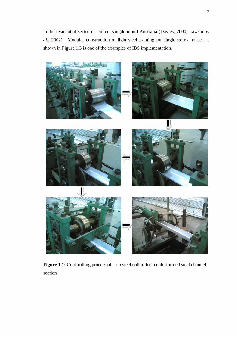
Light steel framing design is generally based on the use of standard C or Z
shaped steel sections produced by cold rolling from strip steel coil as shown in Figure
1.1 and Figure 1.2. Cold-formed sections are generically different from hot rolled
steel sections, such as Universal Beams, which are used in fabricated steelwork. The
steel used in cold-formed sections is relatively thin, typically 0.5 to 2.5 mm, and is
galvanized for corrosion protection. The steel strength is higher than of hot-rolled
steel, where the typical design strength is 350 N/mm2, 450 N/mm2 and even 550
N/mm2 (Hancock, 1998). Besides traditional application as purlin or roof truss, cold-
formed steel sections can be widely used in many sectors of construction, including
industrial buildings, commercial buildings and hotels. It is gaining greater acceptance
in the residential sector in United Kingdom and Australia (Davies, 2000; Lawson et
al., 2002). Modular construction of light steel framing for single-storey houses as
shown in Figure 1.3 is one of the examples of IBS implementation.
Figure 1.1: Cold-rolling process of strip steel coil to form cold-formed steel channel
section
2

Figure 1.2: Common shapes for cold-formed channel sections
Figure 1.3: Cold-formed light steel framing for residential house (adopted from
Lawson et al., 2002)
Most structures, especially the conventional steel buildings are still using the
methods of simple design (simple construction) and rigid design (continuous
construction). Simple design results in a more conservative approach but utilising
heavier sections whereas the continuous design requires more rigorous, non-
economical connection to ensure enough moment resistance. An alternative method
of design known as semi-continuous construction, usually associated with partial
Plain Lipped Sigma
(a) Single C-Sections
(b) Double C-Sections
3
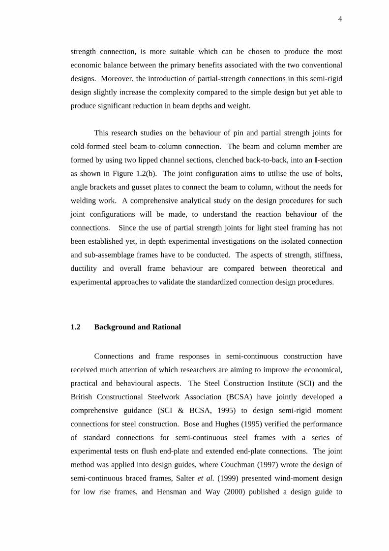
strength connection, is more suitable which can be chosen to produce the most
economic balance between the primary benefits associated with the two conventional
designs. Moreover, the introduction of partial-strength connections in this semi-rigid
design slightly increase the complexity compared to the simple design but yet able to
produce significant reduction in beam depths and weight.
This research studies on the behaviour of pin and partial strength joints for
cold-formed steel beam-to-column connection. The beam and column member are
formed by using two lipped channel sections, clenched back-to-back, into an I-section
as shown in Figure 1.2(b). The joint configuration aims to utilise the use of bolts,
angle brackets and gusset plates to connect the beam to column, without the needs for
welding work. A comprehensive analytical study on the design procedures for such
joint configurations will be made, to understand the reaction behaviour of the
connections. Since the use of partial strength joints for light steel framing has not
been established yet, in depth experimental investigations on the isolated connection
and sub-assemblage frames have to be conducted. The aspects of strength, stiffness,
ductility and overall frame behaviour are compared between theoretical and
experimental approaches to validate the standardized connection design procedures.
1.2 Background and Rational
Connections and frame responses in semi-continuous construction have
received much attention of which researchers are aiming to improve the economical,
practical and behavioural aspects. The Steel Construction Institute (SCI) and the
British Constructional Steelwork Association (BCSA) have jointly developed a
comprehensive guidance (SCI & BCSA, 1995) to design semi-rigid moment
connections for steel construction. Bose and Hughes (1995) verified the performance
of standard connections for semi-continuous steel frames with a series of
experimental tests on flush end-plate and extended end-plate connections. The joint
method was applied into design guides, where Couchman (1997) wrote the design of
semi-continuous braced frames, Salter et al. (1999) presented wind-moment design
for low rise frames, and Hensman and Way (2000) published a design guide to
4

composite connection design for unbraced frames. The development of standardized
flush end-plate and extended end-plates connections were later extended in Malaysia
by Sulaiman (2007) and Saggaff (2007), into partial strength joints and composite
joints for locally produced Trapezoidal Web Profiled (TWP) steel girder.
End-plate connections require both bolting and welding in their fabrication
works. Mottram and Zheng (1999a and 1999b), Pucinotti (2001, 2006) and Danesh et
al. (2007) studied semi-rigid moment joints using top-seat flange-cleat and double
angle web-cleats. The joint configurations formed fully bolted beam-to-column
connection, without the need of welding work. The flange-cleat and web-cleat were
made from angle sections. Pucinotti confirmed such connection configuration were
able to develop desired rotational stiffness. The moment resistance of the connection
was higher than the design strength as predicted by Eurocode 3.
The use of cold-formed steel sections in building construction began in the
1850s, in both the United States and Great Britain (Yu, 2000). However, such
construction methods were not widely used until 1940. Builders noticed that the
design specifications for cold-formed steel construction cannot be covered completely
by the design features of heavy hot-rolled steel. The development of thin walled cold-
formed steel construction in United States is therefore accelerated by American Iron
and Steel Institute (AISI), who sponsored research projects at Cornell University.
They came out with the first design specification in Year 1942 (Hancock et al., 2001).
The investigations resulted in new development of design, concerning the effective
width for stiffened compression elements, reduced working stresses for un-stiffened
elements, web crippling et cetera. Since then researches on light-steel construction
using cold-formed members were carried out in various countries. Developments in
cold-formed steel technology trend to manufacture high strength steel, more complex
section shapes, better corrosion resistance and improved rolling and forming
technology (Davies, 2000). The cold-formed steel researches in Year 1999 to 2001
can be categorized into eleven major areas (Hancock, 2003), such as compression
members with distortional and element buckling, corrugated and curved panels,
connections and fasteners, and mechanical properties of cold-formed steel.
5

Researches on connections and fasteners for cold-formed steel developed from
1997 to 2005 mainly fall in two categories. One focus on the pin connection that able
to produce faster, lighter and economical joints. Self-tapping screws, clinching and
riveting are among the developed methods of typical connection used. Makelainen
and Kesti (1999) and Kaitila et al. (2001) describe a new type of joint called ‘Rosette’,
which is particularly useful for connections in roof truss. The second category of
research studies on the moment connections applied in storage racks, latticed beam
and portal frames. Markazi et al. (1997) studied on the semi-rigid behaviour of
boltless connection for cold-formed steel storage racks. Dubina and Zaharia (1997)
and Dubina (2008) investigated the bolted joints for cold-formed steel truss, latticed
beam and portal frames. Wilkinson (1999), Wilkinson and Hancock (2000) carried
out tests on welded joints for portal frame apex and eaves, while Lim and Nethercot
(2003, 2004, 2005) developed bolted joints for cold-formed steel portal frames. For
beam-to-column connection, Chung and team (Chung & Lau, 1999; Wong & Chung
2002; Chung et al., 2005) reported experimental and analytical testing on bolted
moment connection for cold-formed double channel sections, utilising slip-in gusset
plates.
At present as to the author knowledge, there is no study to extend the
application of partial strength connections as in hot-rolled steel research, into light
steel framing using cold-formed steel section. The use of web-cleat for pin
connection design in cold-formed steel structures has been carried out by Chung and
Lawson (2000), but the top-seat flange-cleats and combined flange-web-cleats for
cold-formed steel beam-to-column connection have not been studied. The British
Standard BS5950 Part 5 (BSI, 1998) and Eurocode BS EN 1993 Part 1.3 (BSI, 2006)
give the permission to design cold-formed steel frame as semi-continuous
construction, where the moment and rotation capacity of joint should be based on
experimental evidence. The detailed design method and requirements, especially for
partial strength connections in cold-formed steel construction has not been concluded.
6
1.3 Problem Statements
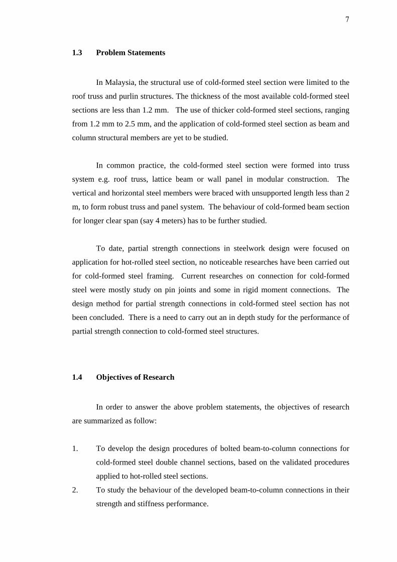
In Malaysia, the structural use of cold-formed steel section were limited to the
roof truss and purlin structures. The thickness of the most available cold-formed steel
sections are less than 1.2 mm. The use of thicker cold-formed steel sections, ranging
from 1.2 mm to 2.5 mm, and the application of cold-formed steel section as beam and
column structural members are yet to be studied.
In common practice, the cold-formed steel section were formed into truss
system e.g. roof truss, lattice beam or wall panel in modular construction. The
vertical and horizontal steel members were braced with unsupported length less than 2
m, to form robust truss and panel system. The behaviour of cold-formed beam section
for longer clear span (say 4 meters) has to be further studied.
To date, partial strength connections in steelwork design were focused on
application for hot-rolled steel section, no noticeable researches have been carried out
for cold-formed steel framing. Current researches on connection for cold-formed
steel were mostly study on pin joints and some in rigid moment connections. The
design method for partial strength connections in cold-formed steel section has not
been concluded. There is a need to carry out an in depth study for the performance of
partial strength connection to cold-formed steel structures.
1.4 Objectives of Research
In order to answer the above problem statements, the objectives of research
are summarized as follow:
1. To develop the design procedures of bolted beam-to-column connections for
cold-formed steel double channel sections, based on the validated procedures
applied to hot-rolled steel sections.
2. To study the behaviour of the developed beam-to-column connections in their
strength and stiffness performance.
7

3. To validate the performance of the proposed connection configurations by
comparing the analytical calculation to experimental results.
1.5 Scope of Work
The scope in this research covers on the behaviour of pin and partial strength
connections in cold-formed lipped Double Channel (DC) section with thickness of 2
mm. Brackets, angle and gusset plate connections were chosen to ensure that the
connections studied in this research fell under the partial strength category and so
suitable to be used in the semi-continuous construction. All connections were formed
using bolts, where no welding work is required.
Analytical investigations were carried to understand the section properties and
member capacities of the cold-formed DC sections. Detailed studies on the
connection design were made in a step by step calculation, to obtain the resistance
capacities of each component of the joint configuration. Comparisons were made
between the increment of beam depth, increment of cleat thickness and changes of
different types of connection configuration. Substantial time was allocated in
conducting the experimental investigations so that the actual behaviour and
characteristics of the proposed connections could be acquired. Beam-to-column
connection set up as cantilever to obtain the moment resistance of joints, and beam
with connections at both ends and with the span of 4 m, set up as sub-assemblage
frames to study the effects of proposed joint types to the light steel frames.
Comparisons between the experimental and analytical investigations lead to a
conclusive design of the proposed connections.
The details of the works involved were divided into several tasks of which,
subsequently, were organised into relevant chapters as described in the Section 1.7
below.
8
1.6 Significant of Study
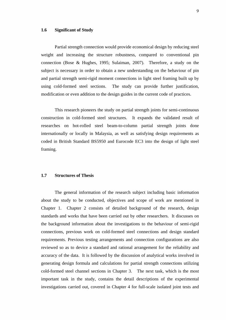
Partial strength connection would provide economical design by reducing steel
weight and increasing the structure robustness, compared to conventional pin
connection (Bose & Hughes, 1995; Sulaiman, 2007). Therefore, a study on the
subject is necessary in order to obtain a new understanding on the behaviour of pin
and partial strength semi-rigid moment connections in light steel framing built up by
using cold-formed steel sections. The study can provide further justification,
modification or even addition to the design guides in the current code of practices.
This research pioneers the study on partial strength joints for semi-continuous
construction in cold-formed steel structures. It expands the validated result of
researches on hot-rolled steel beam-to-column partial strength joints done
internationally or locally in Malaysia, as well as satisfying design requirements as
coded in British Standard BS5950 and Eurocode EC3 into the design of light steel
framing.
1.7 Structures of Thesis
The general information of the research subject including basic information
about the study to be conducted, objectives and scope of work are mentioned in
Chapter 1. Chapter 2 consists of detailed background of the research, design
standards and works that have been carried out by other researchers. It discusses on
the background information about the investigations to the behaviour of semi-rigid
connections, previous work on cold-formed steel connections and design standard
requirements. Previous testing arrangements and connection configurations are also
reviewed so as to device a standard and rational arrangement for the reliability and
accuracy of the data. It is followed by the discussion of analytical works involved in
generating design formula and calculations for partial strength connections utilizing
cold-formed steel channel sections in Chapter 3. The next task, which is the most
important task in the study, contains the detail descriptions of the experimental
investigations carried out, covered in Chapter 4 for full-scale isolated joint tests and
9

Chapter 5 for full-scale sub-assemblage frame tests. Full-scale isolated joint refer to
individual connections which were tested to determine the moment capacities,
stiffness and ductility of the designed joint. The preparation of test specimen, data
acquisition tools and test procedures were discussed in detail. Results acquired from
the isolated tests were used to predict the moment resistance of the connections. In
Chapter 5, the actual responses of pin and partial strength behaviour of connections
over a long beam span is observed and details of calculations to predict the moment
resistance of the beam are addressed. Checking procedures employed are in
accordance with the British Standard and Eurocode 3. Finally the research works is
summarized and concluded in Chapter 6, together with the recommendation for future
works.
10