BEHAVIOR OF HIGH PERFORMANCE CONTINUOUS … · important and special design methods should be...
25
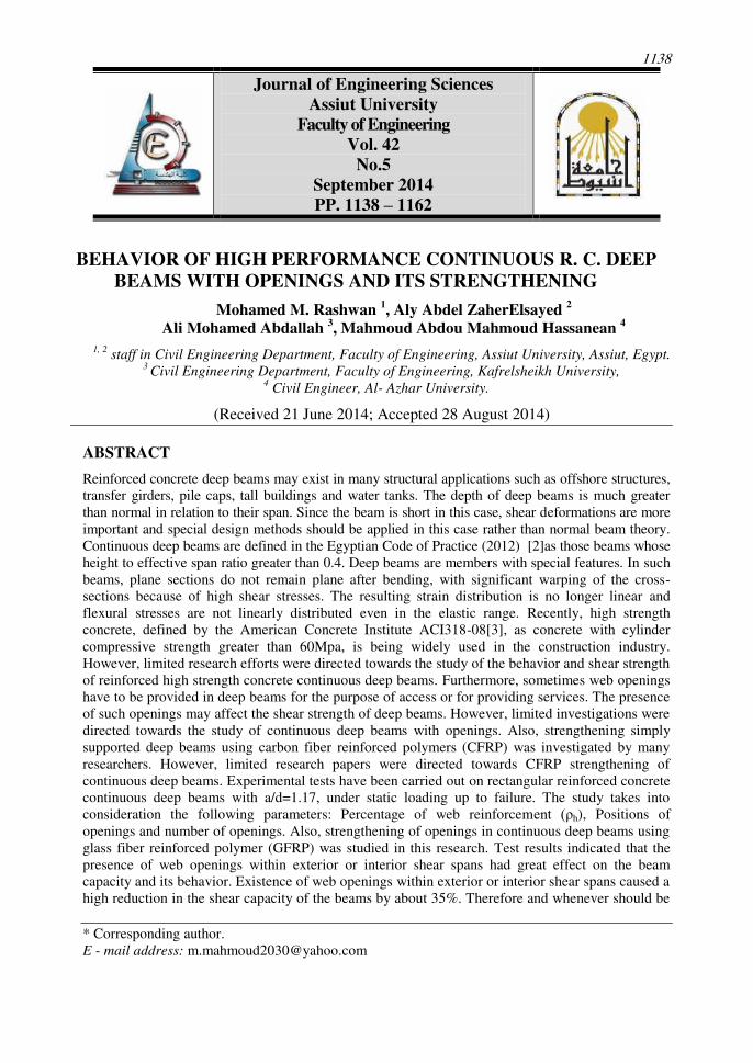
1138 Journal of Engineering Sciences Assiut University Faculty of Engineering Vol. 42 No.5 September 2014 PP. 1138 – 1162 * Corresponding author. E - mail address: [email protected] BEHAVIOR OF HIGH PERFORMANCE CONTINUOUS R. C. DEEP BEAMS WITH OPENINGS AND ITS STRENGTHENING Mohamed M. Rashwan 1 , Aly Abdel ZaherElsayed 2 Ali Mohamed Abdallah 3 , Mahmoud Abdou Mahmoud Hassanean 4 1, 2 staff in Civil Engineering Department, Faculty of Engineering, Assiut University, Assiut, Egypt. 3 Civil Engineering Department, Faculty of Engineering, Kafrelsheikh University, 4 Civil Engineer, Al- Azhar University. (Received 21 June 2014; Accepted 28 August 2014) ABSTRACT Reinforced concrete deep beams may exist in many structural applications such as offshore structures, transfer girders, pile caps, tall buildings and water tanks. The depth of deep beams is much greater than normal in relation to their span. Since the beam is short in this case, shear deformations are more important and special design methods should be applied in this case rather than normal beam theory. Continuous deep beams are defined in the Egyptian Code of Practice (2012) [2]as those beams whose height to effective span ratio greater than 0.4. Deep beams are members with special features. In such beams, plane sections do not remain plane after bending, with significant warping of the cross- sections because of high shear stresses. The resulting strain distribution is no longer linear and flexural stresses are not linearly distributed even in the elastic range. Recently, high strength concrete, defined by the American Concrete Institute ACI318-08[3], as concrete with cylinder compressive strength greater than 60Mpa, is being widely used in the construction industry. However, limited research efforts were directed towards the study of the behavior and shear strength of reinforced high strength concrete continuous deep beams. Furthermore, sometimes web openings have to be provided in deep beams for the purpose of access or for providing services. The presence of such openings may affect the shear strength of deep beams. However, limited investigations were directed towards the study of continuous deep beams with openings. Also, strengthening simply supported deep beams using carbon fiber reinforced polymers (CFRP) was investigated by many researchers. However, limited research papers were directed towards CFRP strengthening of continuous deep beams. Experimental tests have been carried out on rectangular reinforced concrete continuous deep beams with a/d=1.17, under static loading up to failure. The study takes into consideration the following parameters: Percentage of web reinforcement (ρ h ), Positions of openings and number of openings. Also, strengthening of openings in continuous deep beams using glass fiber reinforced polymer (GFRP) was studied in this research. Test results indicated that the presence of web openings within exterior or interior shear spans had great effect on the beam capacity and its behavior. Existence of web openings within exterior or interior shear spans caused a high reduction in the shear capacity of the beams by about 35%. Therefore and whenever should be
Transcript of BEHAVIOR OF HIGH PERFORMANCE CONTINUOUS … · important and special design methods should be...
1138
Journal of Engineering Sciences
Assiut University
Faculty of Engineering
Vol. 42
No.5
September 2014
PP. 1138 – 1162
* Corresponding author.
E - mail address: [email protected]
BEHAVIOR OF HIGH PERFORMANCE CONTINUOUS R. C. DEEP
BEAMS WITH OPENINGS AND ITS STRENGTHENING
Mohamed M. Rashwan 1, Aly Abdel ZaherElsayed
2
Ali Mohamed Abdallah 3, Mahmoud Abdou Mahmoud Hassanean
4
1, 2 staff in Civil Engineering Department, Faculty of Engineering, Assiut University, Assiut, Egypt.
3 Civil Engineering Department, Faculty of Engineering, Kafrelsheikh University,
4 Civil Engineer, Al- Azhar University.
(Received 21 June 2014; Accepted 28 August 2014)
ABSTRACT
Reinforced concrete deep beams may exist in many structural applications such as offshore structures,
transfer girders, pile caps, tall buildings and water tanks. The depth of deep beams is much greater
than normal in relation to their span. Since the beam is short in this case, shear deformations are more
important and special design methods should be applied in this case rather than normal beam theory.
Continuous deep beams are defined in the Egyptian Code of Practice (2012) [2]as those beams whose
height to effective span ratio greater than 0.4. Deep beams are members with special features. In such
beams, plane sections do not remain plane after bending, with significant warping of the cross-
sections because of high shear stresses. The resulting strain distribution is no longer linear and
flexural stresses are not linearly distributed even in the elastic range. Recently, high strength
concrete, defined by the American Concrete Institute ACI318-08[3], as concrete with cylinder
compressive strength greater than 60Mpa, is being widely used in the construction industry.
However, limited research efforts were directed towards the study of the behavior and shear strength
of reinforced high strength concrete continuous deep beams. Furthermore, sometimes web openings
have to be provided in deep beams for the purpose of access or for providing services. The presence
of such openings may affect the shear strength of deep beams. However, limited investigations were
directed towards the study of continuous deep beams with openings. Also, strengthening simply
supported deep beams using carbon fiber reinforced polymers (CFRP) was investigated by many
researchers. However, limited research papers were directed towards CFRP strengthening of
continuous deep beams. Experimental tests have been carried out on rectangular reinforced concrete
continuous deep beams with a/d=1.17, under static loading up to failure. The study takes into
consideration the following parameters: Percentage of web reinforcement (ρh), Positions of
openings and number of openings. Also, strengthening of openings in continuous deep beams using
glass fiber reinforced polymer (GFRP) was studied in this research. Test results indicated that the
presence of web openings within exterior or interior shear spans had great effect on the beam
capacity and its behavior. Existence of web openings within exterior or interior shear spans caused a
high reduction in the shear capacity of the beams by about 35%. Therefore and whenever should be
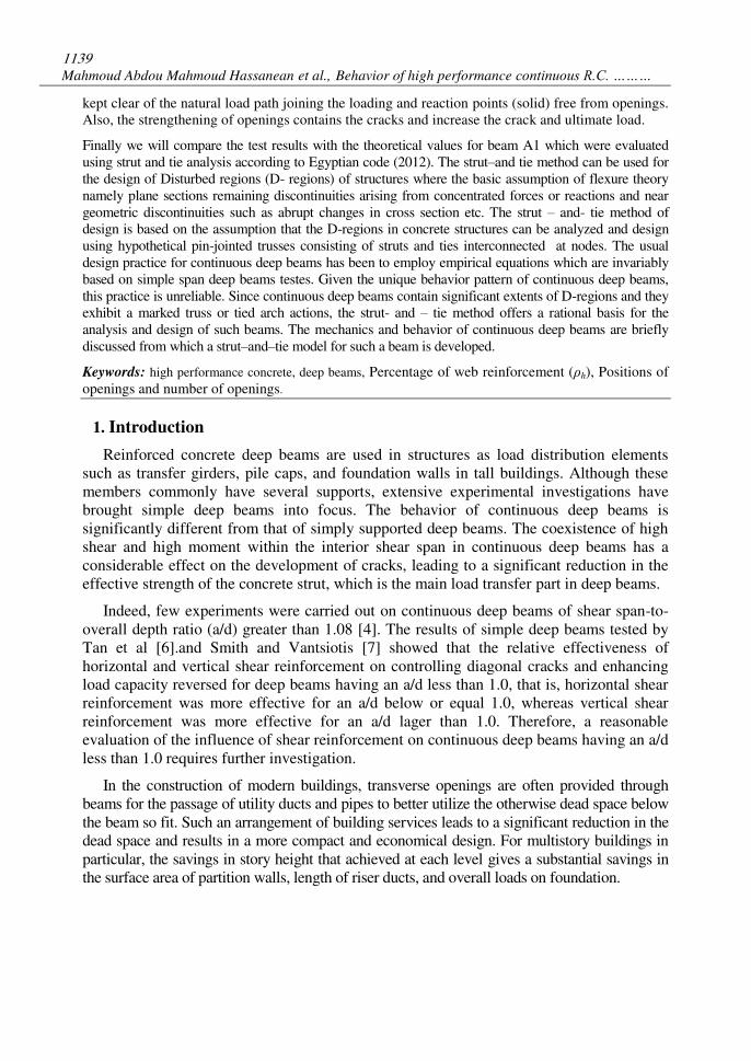
1139
Mahmoud Abdou Mahmoud Hassanean et al., Behavior of high performance continuous R.C. ………
kept clear of the natural load path joining the loading and reaction points (solid) free from openings.
Also, the strengthening of openings contains the cracks and increase the crack and ultimate load.
Finally we will compare the test results with the theoretical values for beam A1 which were evaluated
using strut and tie analysis according to Egyptian code (2012). The strut–and tie method can be used for
the design of Disturbed regions (D- regions) of structures where the basic assumption of flexure theory
namely plane sections remaining discontinuities arising from concentrated forces or reactions and near
geometric discontinuities such as abrupt changes in cross section etc. The strut – and- tie method of
design is based on the assumption that the D-regions in concrete structures can be analyzed and design
using hypothetical pin-jointed trusses consisting of struts and ties interconnected at nodes. The usual
design practice for continuous deep beams has been to employ empirical equations which are invariably
based on simple span deep beams testes. Given the unique behavior pattern of continuous deep beams,
this practice is unreliable. Since continuous deep beams contain significant extents of D-regions and they
exhibit a marked truss or tied arch actions, the strut- and – tie method offers a rational basis for the
analysis and design of such beams. The mechanics and behavior of continuous deep beams are briefly
discussed from which a strut–and–tie model for such a beam is developed.
Keywords: high performance concrete, deep beams, Percentage of web reinforcement (ρh), Positions of
openings and number of openings.
1. Introduction
Reinforced concrete deep beams are used in structures as load distribution elements
such as transfer girders, pile caps, and foundation walls in tall buildings. Although these
members commonly have several supports, extensive experimental investigations have
brought simple deep beams into focus. The behavior of continuous deep beams is
significantly different from that of simply supported deep beams. The coexistence of high
shear and high moment within the interior shear span in continuous deep beams has a
considerable effect on the development of cracks, leading to a significant reduction in the
effective strength of the concrete strut, which is the main load transfer part in deep beams.
Indeed, few experiments were carried out on continuous deep beams of shear span-to-
overall depth ratio (a/d) greater than 1.08 [4]. The results of simple deep beams tested by
Tan et al [6].and Smith and Vantsiotis [7] showed that the relative effectiveness of
horizontal and vertical shear reinforcement on controlling diagonal cracks and enhancing
load capacity reversed for deep beams having an a/d less than 1.0, that is, horizontal shear
reinforcement was more effective for an a/d below or equal 1.0, whereas vertical shear
reinforcement was more effective for an a/d lager than 1.0. Therefore, a reasonable
evaluation of the influence of shear reinforcement on continuous deep beams having an a/d
less than 1.0 requires further investigation.
In the construction of modern buildings, transverse openings are often provided through
beams for the passage of utility ducts and pipes to better utilize the otherwise dead space below
the beam so fit. Such an arrangement of building services leads to a significant reduction in the
dead space and results in a more compact and economical design. For multistory buildings in
particular, the savings in story height that achieved at each level gives a substantial savings in
the surface area of partition walls, length of riser ducts, and overall loads on foundation.
1140
JES, Assiut University, Faculty of Engineering, Vol. 42, No. 5, September 2014, pp. 1138 – 1162
Therefore, special strengthening should be provided around the opening to contain the
width of cracks and to prevent possible premature failure of the beam.
The provision of transverse openings will, however, change the continuous deep beam
behavior into a more complex behavior. It is obvious that the provision of openings produces
discontinuity in the normal flow of stresses, and these results in stress concentration and early
cracking around the opening. The ultimate strength of the beam may also be seriously affected.
2. Experimental work
An experimental program was conducted including twelve reinforced concrete two-span
continuous deep beams. All tested beams were fabricated, instrumented and then tested to failure
under the effect of two concentrated loads one being placed at each span. All beams were made
using high performance concrete. The main objective of this study was to investigate the behavior
of two – span continuous deep beams within the whole range of loading starting from the elastic
range up to the failure of each beam. Many significant factors were considered such as:
1- Percentage of web reinforcement (ρh),
2- Positions and Number of openings being placed within the interior or exterior shear
spans and in flexural region.
3- The effect of strengthening of two–span continuous deep beams on its behavior was
considered in the case of beams provided with openings.
2.1. Materials
2.1.1 High performance concrete (H.P.C). Concrete mix used to produce high performance concrete is given in table (1).
Table 1.
Concrete mix proportion.
concrete Cement kg/m3
Silica-
fume kg/m3
Water liter/m3
Superpl. liter/m3
(BVS)
Fine
aggregate kg/m3
coarse
aggregate kg/m3
(crushed
bazalt)
fcu(kg/cm2)
Slump (cm)
7days 28days
C 500 110 132 17.5 563.59 1127.17 660 872 16
For high performance concrete (fcu= 900 kg/cm2), the constituent materials were:
1- Ordinary Portland cement, its properties agreed with ECP 203.
2- Crushed Bazalt; the used crushed basalt was 20 mm nominal max. Size, 2.70 specific
gravity, and 2.36 t/m3 volume weight.
3- Local sand; the used sand is a medium type one which has a specific gravity and
volume weight of 2.50 and 1.65 t/m3 respectively.
4- Potable water was used.
5- Superplastisizer; the used additive was Addicrete BVS having a density of 1.15 t/m3.
6- Silica fume; it is produced by EFACO (Egyptian Ferro-Alloys Company) which resulting
from the reduction of high-purity quartz with coal in electric arc furnaces in the
manufacture of ferro-silicon. The fume which contains between 92 and 95 percent silicon
dioxide (sio2), and consists of extremely fine spherical glassy particles, is collected by
1141
Mahmoud Abdou Mahmoud Hassanean et al., Behavior of high performance continuous R.C. ………
filtering the gases escaping from the furnaces. The average particle size is 0.1 mm, the
specific surface area is ranging between 12 and 15 m2/g, and the specific gravity is 2.15t/m
3.
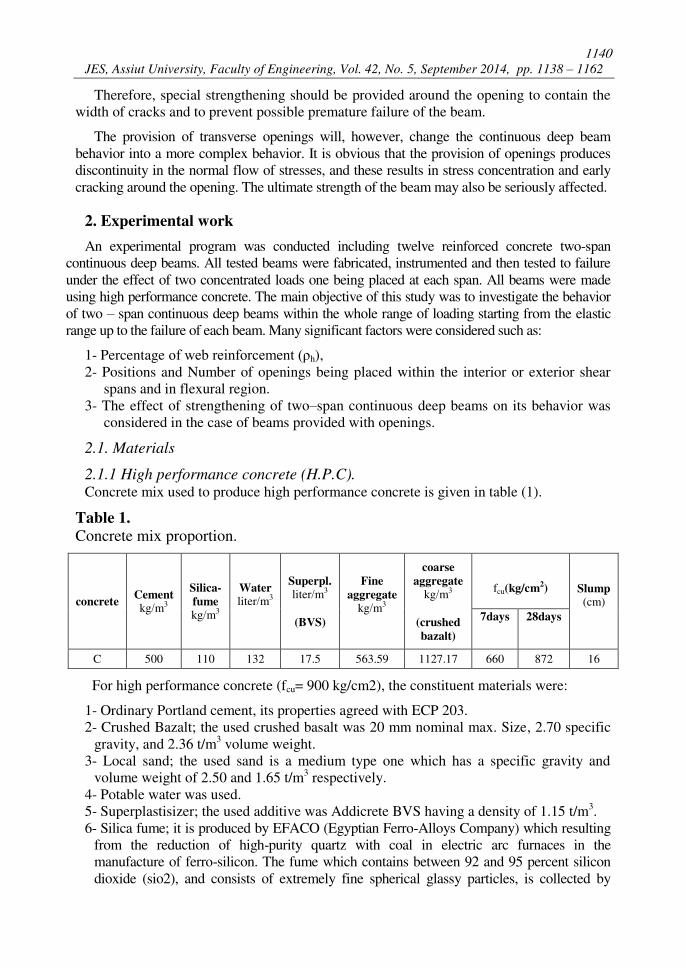
7- Glass fiber: is the common name for glass-reinforced plastic (GRP) or alternatively
glass-fiber reinforced plastic (GFRP) Fiberglass is also known as GFK.
Glass fiber is a fiber reinforced polymer made of plastic reinforced by glass fibers,
commonly woven into a mat. The plastic may be a thermosetting plastic- most often epoxy,
polyester- or vinylester or a thermoplastic. The glass fibers are made of various types of
glass depending upon the fiberglass use.
Glass fiber is a strong lightweight material and is used for many products. Although it's
not as strong and stiff as carbon fiber it is less brittle, and its raw materials are much
cheaper. Its bulk strength and weight are also better than many metals, and it can be more
readily molded into complex shapes. Applications of fiberglass include, aircraft, boats,
automobiles, bath tubs and enclosures, hot tubs, septic tanks, water tanks, roofing, pipes,
cladding, casts, surfboards, and external door skins.
Fig. 1. glass fiber used in strengthening of beams.
Table 2.
Typical properties of fibers.
Type of fiber
Diameter
(mm)
Tensile
Strength
kg/cm2
Young's
modulus
kg/cm2
Elongation
(%)
Glass fiber 1.5-4 2.5*104 8*10
5 3.6
2.2 Test procedure
All beams were tested under two point static loading. The load was increased up to 5.0 tons.
Then; the load was applied in increments each of 5.0 ton for all beams. The load was kept
constant every two successive increments for five minutes. During this period, the mid span
deflection was recorded, cracks propagation were traced, and readings of strain gauges were
recorded. For each beam, the total duration of loading up to failure was different depending upon
the openings position, strengthening of openings, and the founded of horizontal reinforcement.
1142
JES, Assiut University, Faculty of Engineering, Vol. 42, No. 5, September 2014, pp. 1138 – 1162
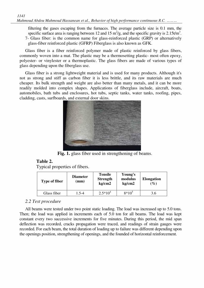
2.3 Measured deformation of beams Strains of concrete and steel were measured by means of electrical strain gauges at the shown
positions in fig (2).The gauges length were 52mm and 800mm for steel and concrete
respectively. The resistance was 600 ohms and gauge factor (2 ± 0.75%). Strain gauges were
connected to strain indicator. The beam deflection was measured using dial gauge with accuracy
of 0.01mm fixed at the position of maximum deflection for each beam as shown in fig. (2).
Fig. 2. Method of measuring deformation of beams.
2.4. Tested beams
The beams were tested with main bottom steel diameter 4#18mm and main top steel
diameter 2#18mm, rectangular cross section equal to 12٘70 cm2).The dimensions of all
openings equal to 18*18 cm. All beams have been casted with concrete having 28 days'
strengths of about 900kg/cm2.The considered total length for all beams were 320cm as
shown in figures (3, 4, 5, 6, 7, 8,9). Table (3) showed the details of the tested beams.
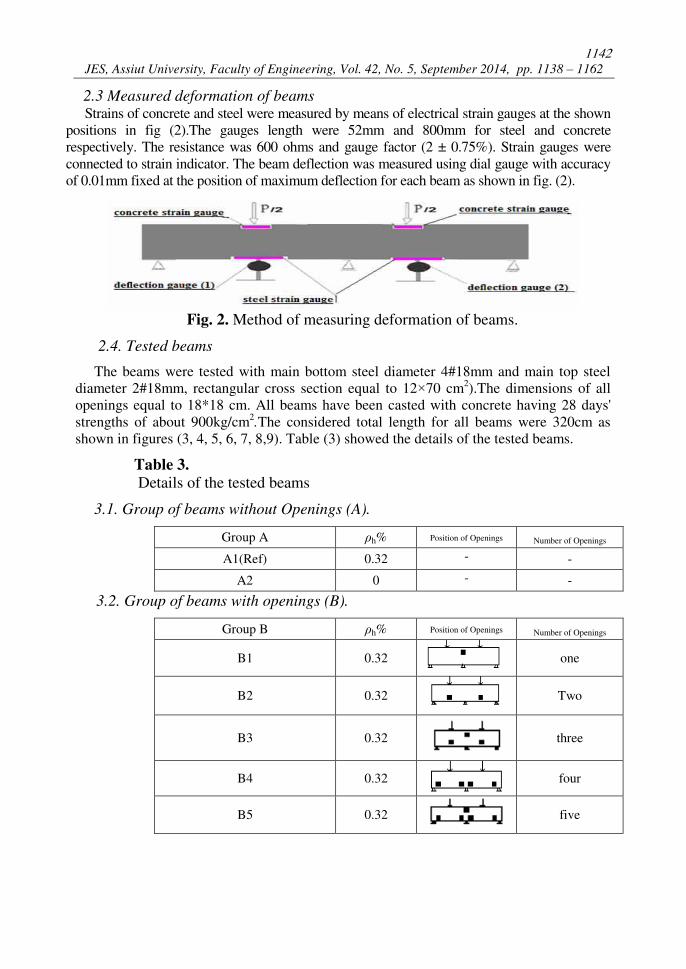
Table 3.
Details of the tested beams
3.1. Group of beams without Openings (A).
Number of Openings Position of Openings ρh% Group A
- - 0.32 A1(Ref)
- - 0 A2
3.2. Group of beams with openings (B).
Number of Openings Position of Openings ρh% Group B
one
0.32 B1
Two
0.32 B2
three
0.32 B3
four
0.32 B4
five
0.32 B5
1143
Mahmoud Abdou Mahmoud Hassanean et al., Behavior of high performance continuous R.C. ………
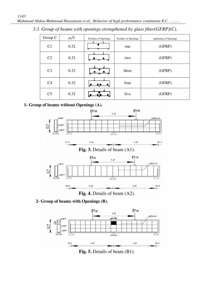
3.3. Group of beams with openings strengthened by glass fiber(GFRP)(C).
ngthening of Openings Number of Openings Position of Openings ρh% Group C
(GFRP) one
0.32 C1
(GFRP) two
0.32 C2
(GFRP) three
0.32 C3
(GFRP) four
0.32 C4
(GFRP) five
0.32 C5
1- Group of beams without Openings (A).
Fig. 3. Details of beam (A1).
Fig. 4. Details of beam (A2).
2- Group of beams with Openings (B).
Fig. 5. Details of beam (B1).
1144
JES, Assiut University, Faculty of Engineering, Vol. 42, No. 5, September 2014, pp. 1138 – 1162
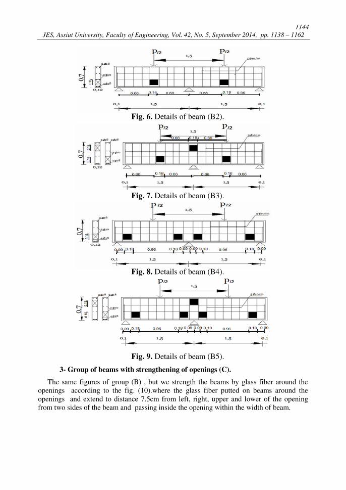
Fig. 6. Details of beam (B2).
Fig. 7. Details of beam (B3).
Fig. 8. Details of beam (B4).
Fig. 9. Details of beam (B5).
3- Group of beams with strengthening of openings (C).
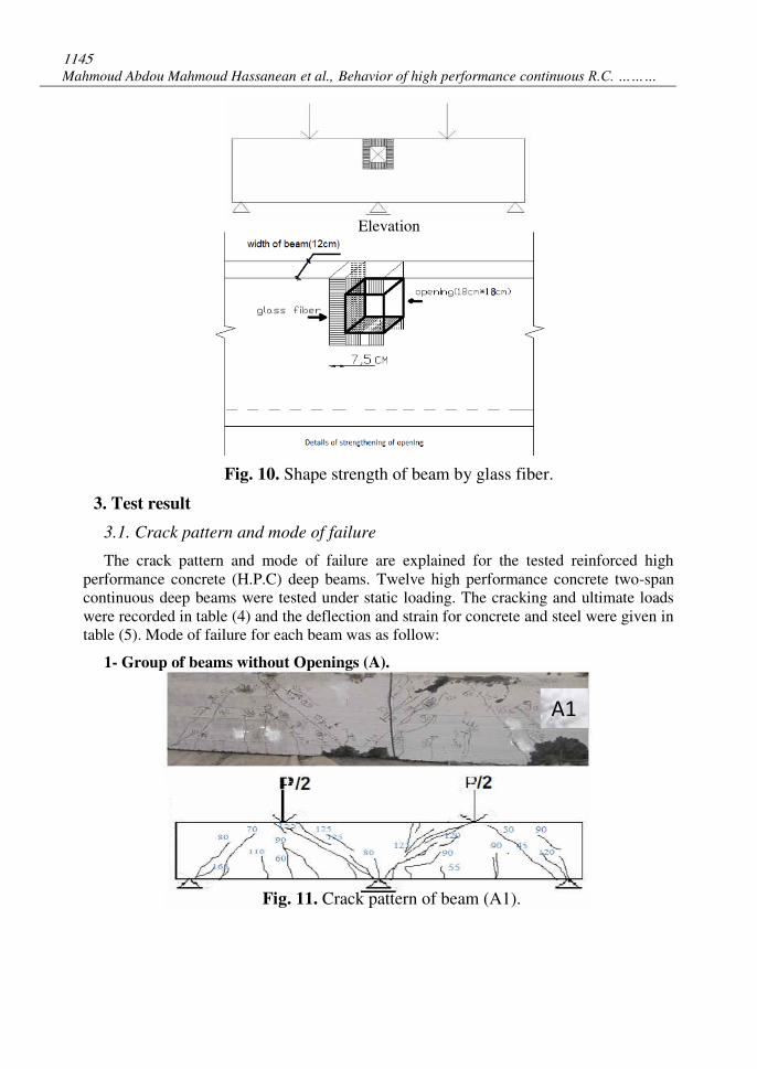
The same figures of group (B) , but we strength the beams by glass fiber around the
openings according to the fig. (10).where the glass fiber putted on beams around the
openings and extend to distance 7.5cm from left, right, upper and lower of the opening
from two sides of the beam and passing inside the opening within the width of beam.
1145
Mahmoud Abdou Mahmoud Hassanean et al., Behavior of high performance continuous R.C. ………
Elevation
Fig. 10. Shape strength of beam by glass fiber.
3. Test result
3.1. Crack pattern and mode of failure
The crack pattern and mode of failure are explained for the tested reinforced high
performance concrete (H.P.C) deep beams. Twelve high performance concrete two-span
continuous deep beams were tested under static loading. The cracking and ultimate loads
were recorded in table (4) and the deflection and strain for concrete and steel were given in
table (5). Mode of failure for each beam was as follow:
1- Group of beams without Openings (A).
Fig. 11. Crack pattern of beam (A1).
A1
1146
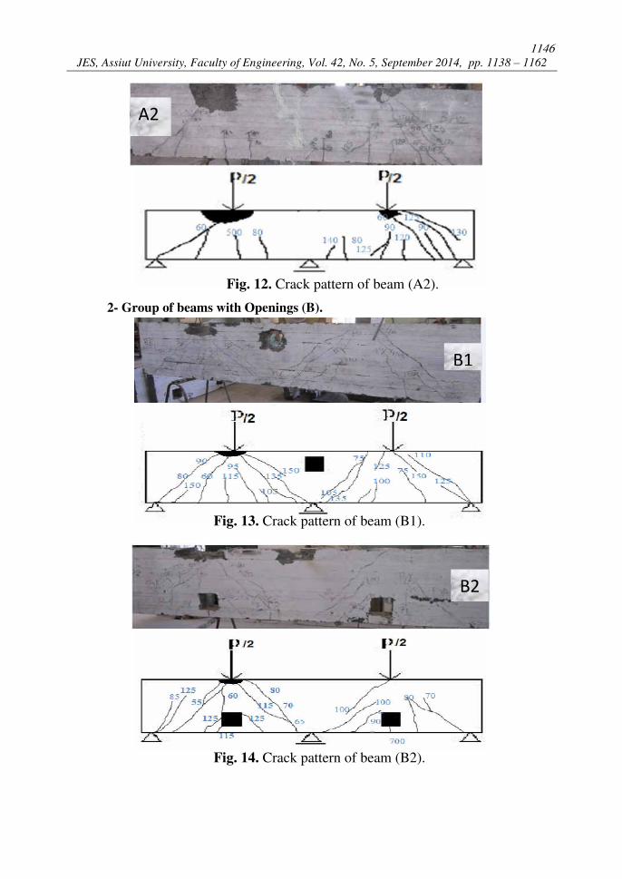
JES, Assiut University, Faculty of Engineering, Vol. 42, No. 5, September 2014, pp. 1138 – 1162
Fig. 12. Crack pattern of beam (A2).
2- Group of beams with Openings (B).
Fig. 13. Crack pattern of beam (B1).
Fig. 14. Crack pattern of beam (B2).
A2
B2
B1
1147
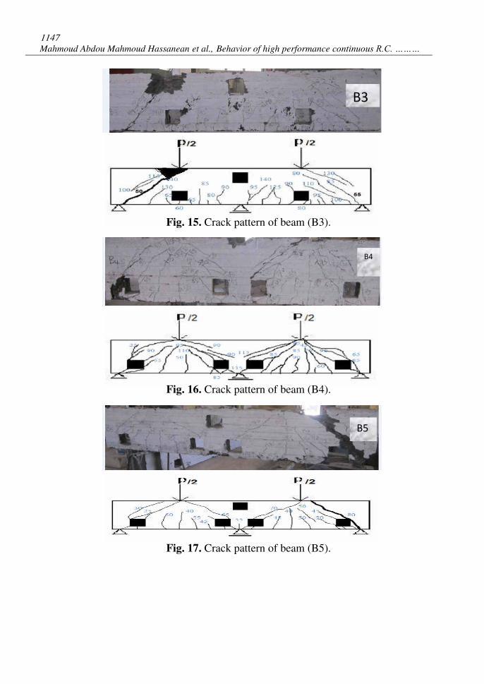
Mahmoud Abdou Mahmoud Hassanean et al., Behavior of high performance continuous R.C. ………
Fig. 15. Crack pattern of beam (B3).
Fig. 16. Crack pattern of beam (B4).
Fig. 17. Crack pattern of beam (B5).
B3
B4
B5
1148
JES, Assiut University, Faculty of Engineering, Vol. 42, No. 5, September 2014, pp. 1138 – 1162
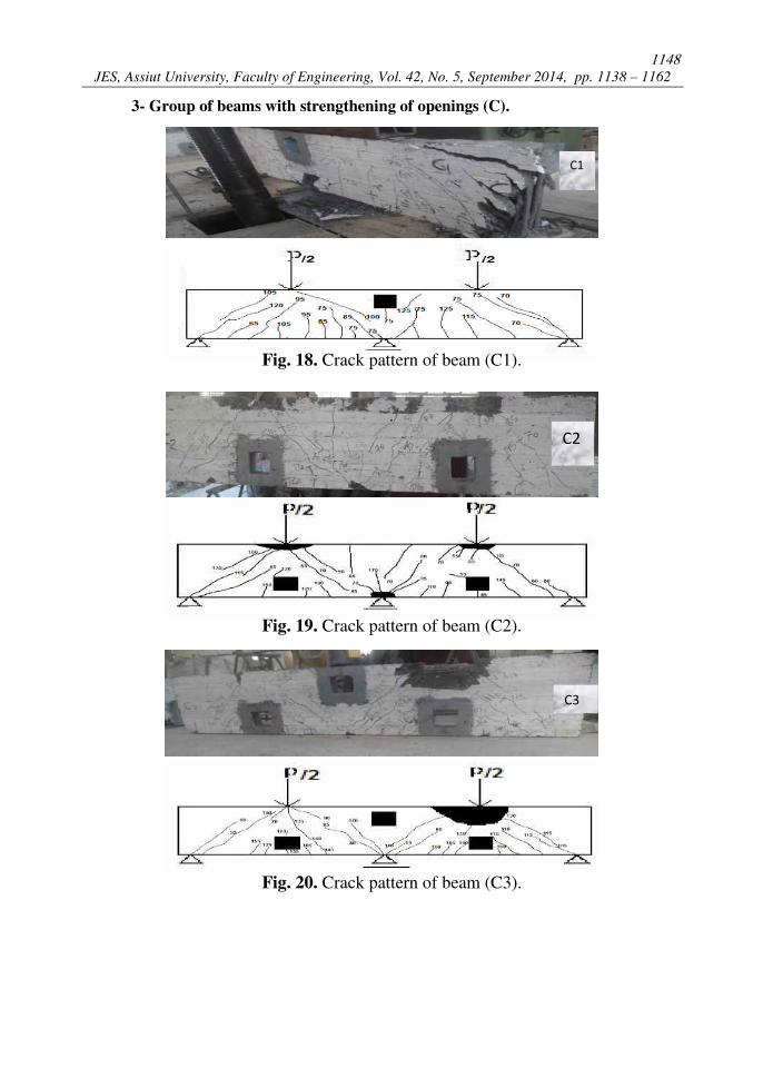
3- Group of beams with strengthening of openings (C).
Fig. 18. Crack pattern of beam (C1).
.
Fig. 19. Crack pattern of beam (C2).
Fig. 20. Crack pattern of beam (C3).
C2
C1
C3
1149
Mahmoud Abdou Mahmoud Hassanean et al., Behavior of high performance continuous R.C. ………
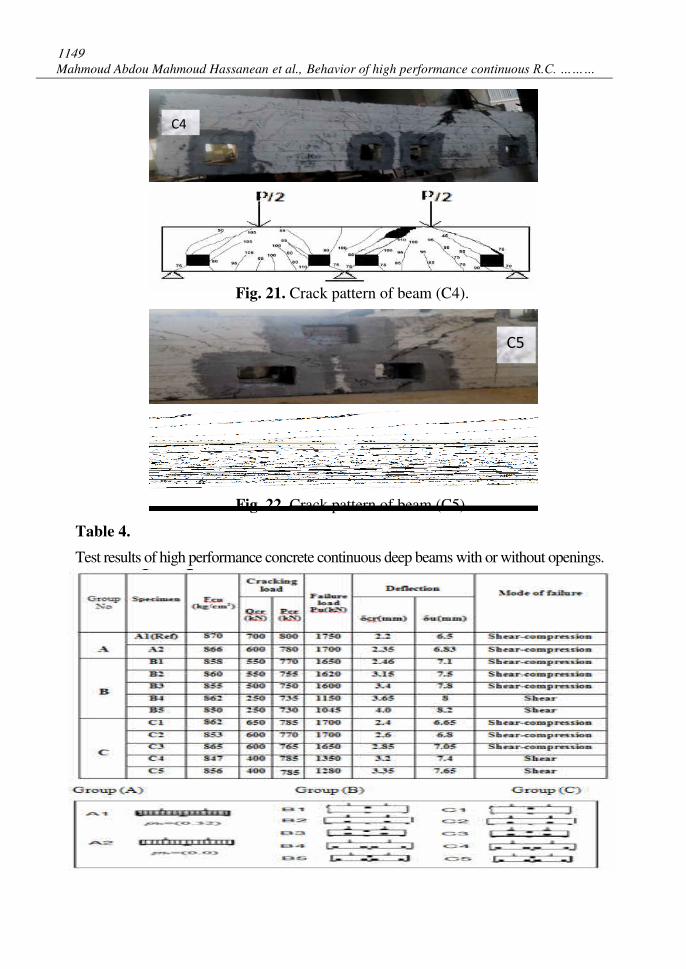
Fig. 21. Crack pattern of beam (C4).
Fig. 22. Crack pattern of beam (C5).
Table 4.
Test results of high performance concrete continuous deep beams with or without openings.
C4
C5
1150
JES, Assiut University, Faculty of Engineering, Vol. 42, No. 5, September 2014, pp. 1138 – 1162
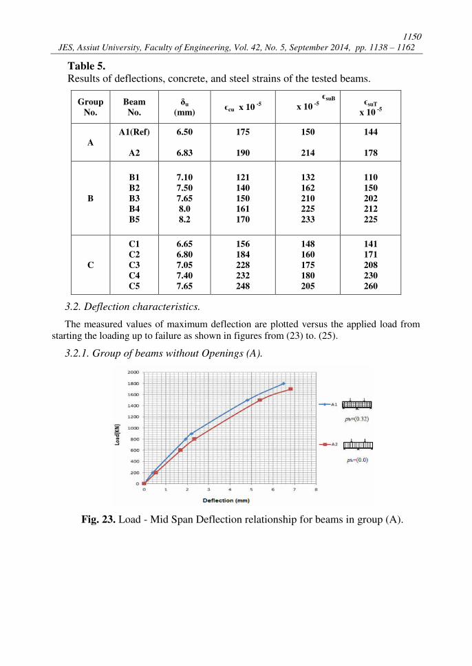
Table 5.
Results of deflections, concrete, and steel strains of the tested beams.
Group
No.
Beam
No.
δu
(mm) ϵcu x 10
-5
ϵsuB
x 10 -5
ϵsuT
x 10 -5
A
A1(Ref)
A2
6.50
6.83
175
190
150
214
144
178
B
B1
B2
B3
B4
B5
7.10
7.50
7.65
8.0
8.2
121
140
150
161
170
132
162
210
225
233
110
150
202
212
225
C
C1
C2
C3
C4
C5
6.65
6.80
7.05
7.40
7.65
156
184
228
232
248
148
160
175
180
205
141
171
208
230
260
3.2. Deflection characteristics.
The measured values of maximum deflection are plotted versus the applied load from
starting the loading up to failure as shown in figures from (23) to. (25).
3.2.1. Group of beams without Openings (A).
Fig. 23. Load - Mid Span Deflection relationship for beams in group (A).
1151
Mahmoud Abdou Mahmoud Hassanean et al., Behavior of high performance continuous R.C. ………
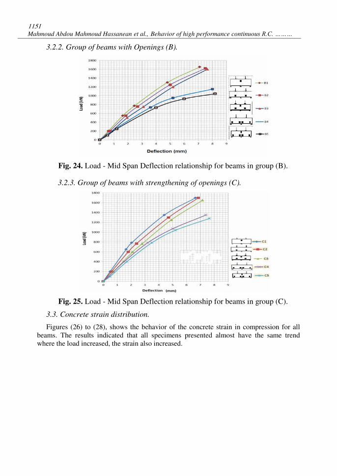
3.2.2. Group of beams with Openings (B).
Fig. 24. Load - Mid Span Deflection relationship for beams in group (B).
3.2.3. Group of beams with strengthening of openings (C).
Fig. 25. Load - Mid Span Deflection relationship for beams in group (C).
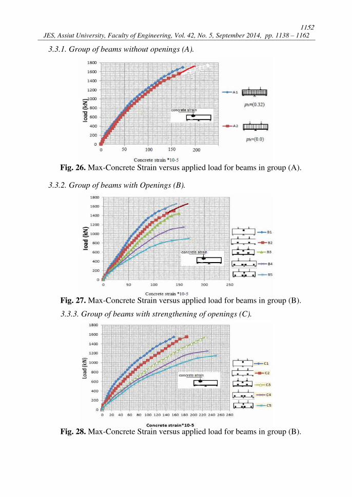
3.3. Concrete strain distribution.
Figures (26) to (28), shows the behavior of the concrete strain in compression for all
beams. The results indicated that all specimens presented almost have the same trend
where the load increased, the strain also increased.
1152
JES, Assiut University, Faculty of Engineering, Vol. 42, No. 5, September 2014, pp. 1138 – 1162
3.3.1. Group of beams without openings (A).
Fig. 26. Max-Concrete Strain versus applied load for beams in group (A).
3.3.2. Group of beams with Openings (B).
Fig. 27. Max-Concrete Strain versus applied load for beams in group (B).
3.3.3. Group of beams with strengthening of openings (C).
Fig. 28. Max-Concrete Strain versus applied load for beams in group (B).
1153
Mahmoud Abdou Mahmoud Hassanean et al., Behavior of high performance continuous R.C. ………
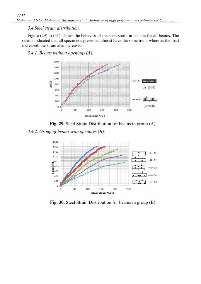
3.4 Steel strain distribution.
Figure (29) to (31), shows the behavior of the steel strain in tension for all beams. The
results indicated that all specimens presented almost have the same trend where as the load
increased, the strain also increased.
3.4.1. Beams without openings (A).
Fig. 29. Steel Strain Distribution for beams in group (A).
3.4.2. Group of beams with openings (B).
Fig. 30. Steel Strain Distribution for beams in group (B).
1154
JES, Assiut University, Faculty of Engineering, Vol. 42, No. 5, September 2014, pp. 1138 – 1162
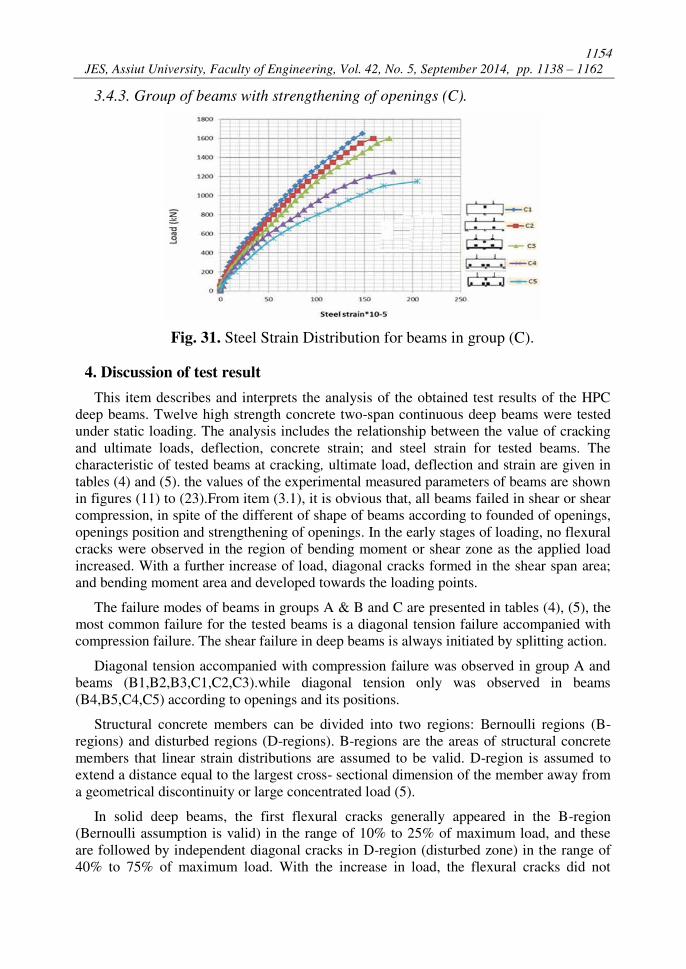
3.4.3. Group of beams with strengthening of openings (C).
Fig. 31. Steel Strain Distribution for beams in group (C).
4. Discussion of test result
This item describes and interprets the analysis of the obtained test results of the HPC
deep beams. Twelve high strength concrete two-span continuous deep beams were tested
under static loading. The analysis includes the relationship between the value of cracking
and ultimate loads, deflection, concrete strain; and steel strain for tested beams. The
characteristic of tested beams at cracking, ultimate load, deflection and strain are given in
tables (4) and (5). the values of the experimental measured parameters of beams are shown
in figures (11) to (23).From item (3.1), it is obvious that, all beams failed in shear or shear
compression, in spite of the different of shape of beams according to founded of openings,
openings position and strengthening of openings. In the early stages of loading, no flexural
cracks were observed in the region of bending moment or shear zone as the applied load
increased. With a further increase of load, diagonal cracks formed in the shear span area;
and bending moment area and developed towards the loading points.
The failure modes of beams in groups A & B and C are presented in tables (4), (5), the
most common failure for the tested beams is a diagonal tension failure accompanied with
compression failure. The shear failure in deep beams is always initiated by splitting action.
Diagonal tension accompanied with compression failure was observed in group A and
beams (B1,B2,B3,C1,C2,C3).while diagonal tension only was observed in beams
(B4,B5,C4,C5) according to openings and its positions.
Structural concrete members can be divided into two regions: Bernoulli regions (B-
regions) and disturbed regions (D-regions). B-regions are the areas of structural concrete
members that linear strain distributions are assumed to be valid. D-region is assumed to
extend a distance equal to the largest cross- sectional dimension of the member away from
a geometrical discontinuity or large concentrated load (5).
In solid deep beams, the first flexural cracks generally appeared in the B-region
(Bernoulli assumption is valid) in the range of 10% to 25% of maximum load, and these
are followed by independent diagonal cracks in D-region (disturbed zone) in the range of
40% to 75% of maximum load. With the increase in load, the flexural cracks did not
1155
Mahmoud Abdou Mahmoud Hassanean et al., Behavior of high performance continuous R.C. ………
develop anymore and inclined cracks newly appeared in the strut direction. The beam
ultimately failed at concrete struts joining the load points and supports.
In deep beams with openings in shear region, the first diagonal cracks occurred near the
bottom and top corners of openings. These cracks gradually developed towards the load
points and Flexural cracks appeared in the B-region in the range of 50% to 80% of
maximum load and developed toward corner of the opening.
In deep beams with openings in moment region, it behaved like a solid beams.
The presence of openings has a considerable effect on pattern of cracks and modes of
failure when openings founded in shear zone. When the openings founded in moment
zones the failure happened due to diagonal tension accompanied with compression. But
when openings founded in shear zones the failure happened due to diagonal tension only.
The strengthening of openings with (glass fiber reinforced polymer) has a considerable
effect on pattern of cracks and modes of failure, the strengthening of openings contain the
width of cracks and increase the cracking loads and ultimate loads.
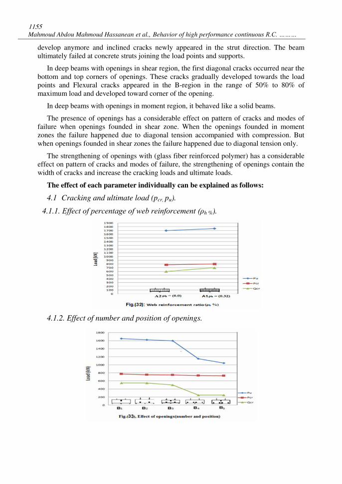
The effect of each parameter individually can be explained as follows:
4.1 Cracking and ultimate load (pcr, pu).
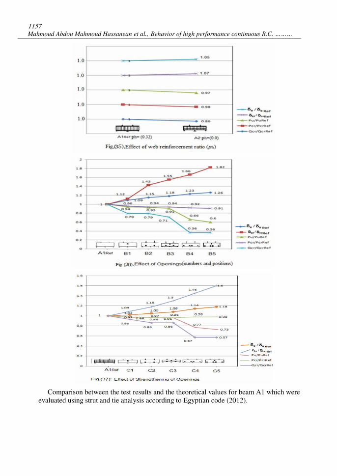
4.1.1. Effect of percentage of web reinforcement (ρh %).
4.1.2. Effect of number and position of openings.
1156
JES, Assiut University, Faculty of Engineering, Vol. 42, No. 5, September 2014, pp. 1138 – 1162
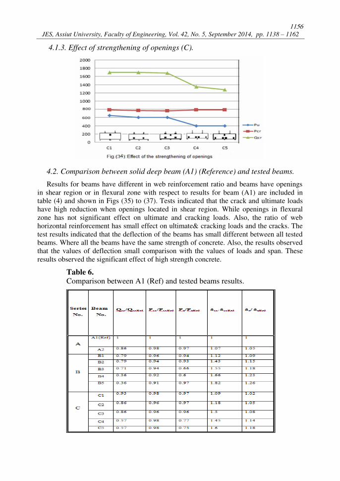
4.1.3. Effect of strengthening of openings (C).
4.2. Comparison between solid deep beam (A1) (Reference) and tested beams.
Results for beams have different in web reinforcement ratio and beams have openings
in shear region or in flexural zone with respect to results for beam (A1) are included in
table (4) and shown in Figs (35) to (37). Tests indicated that the crack and ultimate loads
have high reduction when openings located in shear region. While openings in flexural
zone has not significant effect on ultimate and cracking loads. Also, the ratio of web
horizontal reinforcement has small effect on ultimate& cracking loads and the cracks. The
test results indicated that the deflection of the beams has small different between all tested
beams. Where all the beams have the same strength of concrete. Also, the results observed
that the values of deflection small comparison with the values of loads and span. These
results observed the significant effect of high strength concrete.
Table 6.
Comparison between A1 (Ref) and tested beams results.
1157
Mahmoud Abdou Mahmoud Hassanean et al., Behavior of high performance continuous R.C. ………
Comparison between the test results and the theoretical values for beam A1 which were
evaluated using strut and tie analysis according to Egyptian code (2012).
1158
JES, Assiut University, Faculty of Engineering, Vol. 42, No. 5, September 2014, pp. 1138 – 1162
4.3. Analysis of continuous solid deep beam by strut and tie model
The strut–and tie method can be used for the design of Disturbed regions (D- regions)
of structures where the basic assumption of flexure theory namely plane sections
remaining discontinuities arising from concentrated forces or reactions and near geometric
discontinuities such as abrupt changes in cross section etc. The strut – and- tie method of
design is based on the assumption that the D-regions in concrete structures can be
analyzed and design using hypothetical pin-jointed trusses consisting of struts and ties
interconnected at nodes . The usual design practice for continuous deep beams has been to
employ empirical equations which are invariably based on simple span deep beams testes.
Given the unique behavior pattern of continuous deep beams, this practice is unreliable.
Since continuous deep beams contain significant extents of D-regions and they exhibit a
marked truss or tied arch actions, the strut- and – tie method offers a rational basis for the
analysis and design of such beams. The mechanics and behavior of continuous deep beams
are briefly discussed from which a strut–and–tie model for such a beam is developed.
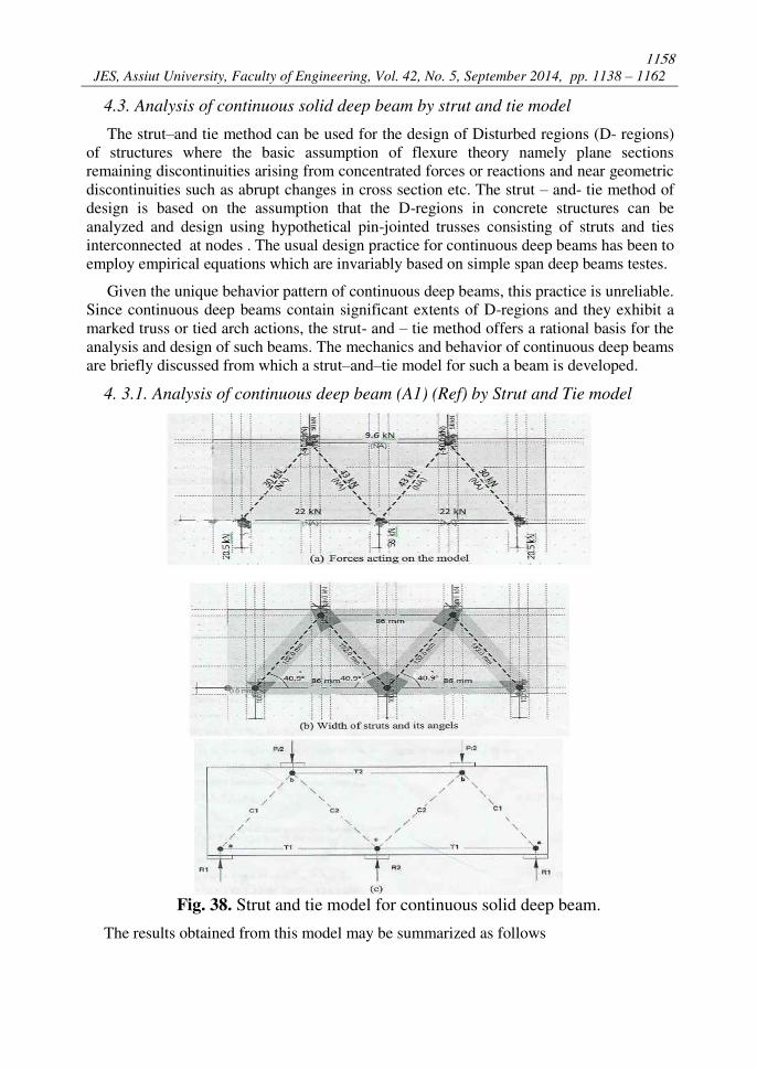
4. 3.1. Analysis of continuous deep beam (A1) (Ref) by Strut and Tie model
Fig. 38. Strut and tie model for continuous solid deep beam.
The results obtained from this model may be summarized as follows
1159
Mahmoud Abdou Mahmoud Hassanean et al., Behavior of high performance continuous R.C. ………
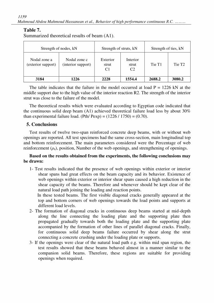
Table 7.
Summarized theoretical results of beam (A1).
Strength of nodes, kN
Strength of struts, kN
Strength of ties, kN
Nodal zone a
(exterior support)
Nodal zone c
(interior support)
Exterior
strut
C1
Interior
strut
C2
Tie T1
Tie T2
3184 1226 2228 1554.4 2688.2 3080.2
The table indicates that the failure in the model occurred at load P = 1226 kN at the
middle support due to the high value of the interior reaction R2. The strength of the interior
strut was close to the failure of the model.
The theoretical results which were evaluated according to Egyptian code indicated that
the continuous solid deep beam (A1) achieved theoretical failure load less by about 30%
than experimental failure load. (Pth/ Pexp) = (1226 / 1750) = (0.70).
5. Conclusions
Test results of twelve two-span reinforced concrete deep beams, with or without web
openings are reported. All test specimens had the same cross-section, main longitudinal top
and bottom reinforcement. The main parameters considered were the Percentage of web
reinforcement (ρh), position, Number of the web openings, and strengthening of openings.
Based on the results obtained from the experiments, the following conclusions may
be drawn:
1- Test results indicated that the presence of web openings within exterior or interior
shear spans had great effects on the beam capacity and its behavior. Existence of
web openings within exterior or interior shear spans caused a high reduction in the
shear capacity of the beams. Therefore and whenever should be kept clear of the
natural load path joining the loading and reaction points.
In these tested beams. The first visible diagonal cracks generally appeared at the
top and bottom corners of web openings towards the load points and supports at
different load levels.
2- The formation of diagonal cracks in continuous deep beams started at mid-depth
along the line connecting the loading plate and the supporting plate then
propagated gradually towards both the loading plate and the supporting plate
accompanied by the formation of other lines of parallel diagonal cracks. Finally,
for continuous solid deep beams failure occurred by shear along the strut
connecting a concrete crushing under the loading plate or supports.
3- If the openings were clear of the natural load path e.g. within mid span region, the
test results showed that these beams behaved almost in a manner similar to the
companion solid beams. Therefore, these regions are suitable for providing
openings when required.
1160
JES, Assiut University, Faculty of Engineering, Vol. 42, No. 5, September 2014, pp. 1138 – 1162
4- Solid continuous deep beams showed more distributed cracks than beams with
openings within exterior or interior shear spans, where dangerous cracks would be
situated above and below the openings. Therefore, the regions above and below the
openings should be well protected.
5- In the design of the majority of solid deep beams, it is usually necessary to consider
shear for the ultimate state only. In the design of deep beams with openings,
however, shear may also be important considerations for the serviceability limit state
of cracking. Continuous deep beams of the present study showed severe cracks
before failure, therefore, serviceability limits should be considered in the design.
6- Test results observed that the horizontal web reinforcement ratio (ρh) has significant
effect on behavior of cracks. But has not significant effect on ultimate loads.
7- Test results indicated that the strengthening around the openings by GFRP has
significant effect when openings located at shear region where the strengthening
enhancement the cracking loads and the failure loads. Also, the strengthening
contains the cracks around the openings. But has not significant effect if the
openings in moment region.
REFERENCES
[1] Aguilar, G, Matamoros, AB, Parra-Montesinos,GJ,Ramirez Jand Wight JK (2002)"
Experimental Evaluation of Deign Procedures for Shear Strength of Deep R.C.Beams" ACI
Structural Journal,Vol.99 No (4) PP. 539-548.
[2] Egyptian Code of practice, Permanent Committee For the code, "Design and construction of
reinforced concrete structures "Fourth Edition, Housing and Building research Center and
Physical Planning , Cairo, Egypt, 2012 .
[3] ACI, “Building Code Requirements for Structural Concrete (ACI 318-08) and Commentary,
section 10.7 and R10.7,” 317-318, 2011. [4] Yang , K.H, chung, H.S, and Ashour, A.F," Influence of Shear Reinforcement on R.C.
Continuous Deep Beams " ACI Structural Journal Vol. 104, No.4,July-Aug, 2007, PP. 420 – 429.
[5] Nile P.Bahen ,"Strut-and-Tie Modeling for disturbed regions in structural concrete members with
Emphasis on Deep Beams", a thesis submitted in partial fulfillment of requirement for the degree
of Master of Science in civil and Environmental Engineering, University of Nevada, Reno.
[6] Tan, K.H, Tong, K, and Tang, C.Y, “Consistent Strut and Tie Modeling of Deep Beams with
Web Openings” Magazine of Concrete Research, Feb .2003, Vol . 55, No.1 PP. 65 – 75.
[7] Smith ,K. N., and Vantsiotis, A.s."Deep Beam Test Results Compared with Present Building
Code Models."ACI Journal, Title no.79-28, July-August 1982, pp.280 287.

1161
Mahmoud Abdou Mahmoud Hassanean et al., Behavior of high performance continuous R.C. ………
سل الكمرا الخرساني المسلح العمي المستمرة
ا يت ت الفتحا م العالي ا ا الم الملخص العربى
ص ئ ا ي ي اا ي ا ا ا ي ا ي . ا ا ا ا ا ا ا ا ي ئي ف ا ا
ي ح ا اي ا ي ي اأح ا أ ي ي ا ا ا ا ي ي . اا ا ا ا في ي ا ا غي ا : أ ا ي في ا يح اأف ي ا ح
ي ا ق ا اء في أقصي ا أ ف ف اي ا ا ي ا ف ي ا أ ا ا ش في ا أقصي ا ا ي ا ا
ي ا ا ا ا ف ,ا ا ا ي ا ي أ ا ي ا ف ا ي ح ا ا ي ي أف ي ا ف ا ا ي ائح أ ا ش . ي
ي صف ي ي ا ي ي ح أ اخ ي ي ص ا ي ا. ا ا
ي ا ي ح ص ا ا ي ا ي ا ص ا ي ا 900 /2 ي ح ا ي ا ي اخ ا ا اخ ي ا ء : قي اا
ي ا ف ا إض ي ا ي ف ي ا ئي ي ا , قي اا ا في اأش ي أح أ ش ا ا ا ي ا
ي ا ي ا ئي ا ي ش ا ا ي .أح اا
ر النتائج ما يلي : ق اظء - 1 ف ي ي ي أ ي ا ي ا اخ ف في ا ا ئ أ ا ضح ا
ا ي . ا ص ا ا ف في ا ي ح في ا 35حي أ اص أ , % ي ا ي ا ي حي ا في . ي ا ا
ف في ا ا ي ف ا ي ي في ا ا اح أ ا ا ا اي ا ي ا ي ي . ا
ف - 2 صف اا أ في ي ا ا ا ي في ا ئ أ ا ا ض ا أي ا ي ا ي ي ا خا ا ا ي , ا ا حي ا ي ي
ي ا ي ي ا , ص ق ي ا ا ا ي في ا ي ي اا في اغ ف في ا ص غ . خا ا
ا -3 ئ ااخ أ ا ض ا ا أي في ا أ ي ف اص ا ا ي ي ف , ش ض ا ي ا ي ف ا
. أ ف في - 4 ا ا ي أ ا ص ي ا ا ا ا ض ا أ
ف ي ا ا ف ي أ ف ي , ا حي ش خ ق ح ا ف اي . ي
ا أقصي ق ف- 5 ص ي في ا ي ا ا ا ي ا ص ا , في ي ا ص في ا أ غي في اا حي أ ا ح ا ف ي اخ ق ا في ا ا ي ا
ي اح ق اا ي ا ي ,ا ص غي ي أخ في اا في ا ح ا ي ف

1162
JES, Assiut University, Faculty of Engineering, Vol. 42, No. 5, September 2014, pp. 1138 – 1162
ي ي - 6 أ ي ي ش ا اضح ي أ ي يح اأف ي ا ئ أ ح ض ا أا ف ي في ا اا غي . ي ح ا
ي ف - 7 أ ف ا ي ائح أ ا ش ف ي ا اح أ ا ئ ا ف في ا ي, ا ح اا ي ح ا ي ي ي , حي ا ف ا اض
ف ي ي ا ح ا ي , أ ا ي في ا ف ا ي ا ي أ ئ اي ي ح اا ي ش ا أ ي ي أ ي ق ح , . ي أ ا ا ا ض أي ا أي ف في ا ا ا % 25ي اق % 17 ا ا ا
ف ي ا ا ا ي . ا