BEETLE /FUSION - dieboldnixdorf.com · Local Restriction of 802.11a, 802.11b, 802.11g, and 802.11n...
60
Installation Guide BEETLE /FUSION
Transcript of BEETLE /FUSION - dieboldnixdorf.com · Local Restriction of 802.11a, 802.11b, 802.11g, and 802.11n...

Installation Guide
BEETLE /FUSION

The reproduction, transmission or use of this document or its contents is not
permitted without express authority. Offenders will be liable for damages.
All rights, including rights created by patent grant or registration of a utility model or design, are reserved.
Delivery subject to availability; technical modifications possible.
Copyright© Wincor Nixdorf International GmbH, 2011

BEETLE /FUSION Installation Guide
Edition Jul 2012

Contents
Fusion – Installation Guide 01750166737 F
Contents
Manufacturer’s Certification ..........................................................................1 Tested Safety ...............................................................................................1 FCC-Class A Declaration .............................................................................2 BSMI (EMC for Taiwan) ...............................................................................2
Technical & Regulatory Information on Wireless ........................................3 Wireless Interoperability ...............................................................................3 Safety Instructions........................................................................................3 Regulatory Information .................................................................................4
Local Restriction of 802.11a, 802.11b, 802.11g, and 802.11n Radio Usage.......................................................................................................4
Europe-EU Declaration of Conformity ..........................................................5 France......................................................................................................6
Introduction.....................................................................................................7 Symbols used in this guide...........................................................................7 Important safety precautions ........................................................................8 Installation notes ..........................................................................................8 General safety precautions ..........................................................................8
Contents
01750166737 F BEETLE /FUSION - Installation Guide
Planning the Installation ..............................................................................10 Device dimensions .....................................................................................10
BEETLE /Fusion - Desktop version.......................................................11 BEETLE /Fusion - Wall-mount version..................................................12
Required operation space ..........................................................................13 Installation site requirements......................................................................14
Desktop version .....................................................................................14 Wall mount version.................................................................................15
Installation.....................................................................................................19 Removing the packaging............................................................................19
Installing desktop stand onto panel PC module .....................................20 Installing desktop stand-2 onto panel PC module..................................30
Installing RAM onto panel PC module........................................................35 Installing harddisk onto panel PC module ..................................................37 Connecting the power cord ........................................................................40
Desktop version .....................................................................................40 Wall mount version.................................................................................41
Installation of wall mount unit .....................................................................43 Mounting wall mount back plate onto the wall........................................44 Mounting wall mount front plate onto the system...................................45 Securing system onto wall .....................................................................46
Appendix .......................................................................................................47 Technical Data for BEETLE /Fusion 12......................................................47 Technical data for BEETLE /Fusion 15 ......................................................48 Technical data for BEETLE /Fusion 19 ......................................................49 Operating Environment for IR Touch..........................................................50

Contents
Fusion – Installation Guide 01750166737 F
AC Power Adapter......................................................................................51 Power Cord Selection.................................................................................52 I/O connection ports ...................................................................................53

Manufacturer’s Certification
01750166737 F BEETLE /FUSION – Installation Guide 1
Manufacturer’s Certification
The device complies with the requirements of the EEC directive 2004/108/EC with regard to “Electromagnetic compatibility” and 2006/95/EC “Low Voltage Directive”.
Therefore, you will find the CE mark on the device or packaging.
Tested Safety
The device complies with the requirements of the EEC directive 89/336/EEC with regard to “Electromagnetic compatibility” and 73/23/ECC “Low Voltage Directive”.
In addition, the device has received the UL symbol and cUL symbol.
Manufacturer’s certification
2 BEETLE /FUSION – Installation Guide 01750166737 F
FCC-Class A Declaration
This equipment has been tested and found to comply with the limits for a Class A digital device, pursuant to part 15 of the FCC Rules. These limits are designed to provide reasonable protection against harmful interference when the equipment is operated in a commercial environment. This equipment generates, uses, and can radiate radio frequency energy and, if not in-stalled and used in accordance with the instruction manual, may cause harmful interference to radio communications.
Operation of this equipment in a residential area is likely to cause harmful interference in which case the user will be required to correct the interference at his own expense.
Le présent appareil numérique ne génère pas de bruits radioélectriques dépassant les limites applicable aux appareils numériques de la “Class A” prescrites dans le Règlement sur le brouillage radioélectrique édicté par le ministère des Communications du Canada.
BSMI (EMC for Taiwan)
The device complies with the requirements of the BSMI (Bureau of Standards, Metrology and Inspection, Ministry of Economic Affairs) directive CNS14348 with regard to “Electromagnetic compatibility” with the limits for a Class B product.

Manufacturer’s Certification
01750166737 F BEETLE /FUSION – Installation Guide 3
Technical & Regulatory Information on Wireless
Wireless Interoperability The WLAN adapter integrated in the BEETLE /Fusion is designed to be interoperable with any wireless LAN product that is based on direct sequence spread spectrum (DSSS) and to comply with the following standards:
• IEEE Std 802.11b Standard on 2.4 GHz Wireless LAN • IEEE Std 802.11g Standard on 2.4 GHz Wireless LAN • IEEE Std 802.11a Standard on 5 GHz Wireless LAN • IEEE Std 802.11 Draft-N on 5 GHz Wireless LAN
Safety Instructions The WLAN adapter, like other radio devices, emits radio frequency electromagnetic energy. The level of energy emitted by the adapter, however, is less than the electromagnetic energy emitted by other wireless devices such as mobile phones. The adapter operates within the guidelines found in radio frequency safety standards and recommendations. These standards and recommendations reflect the consensus of the scientific community and result from deliberations of panels and committees of scientists who continually review and interpret the extensive research literature. In some situations or environments, the use of the adapter may be restricted by the proprietor of the building or responsible representatives of the applicable organization. Examples of such situations may include:
• Hospital
• Any other environment where the risk of interference with other devices or services is perceived or identified as being harmful

Manufacturer’s certification
4 BEETLE /FUSION – Installation Guide 01750166737 F
If you are uncertain of the policy that applies to the use of wireless devices in a specific organization or environment (a hospital, for example), you are encouraged to ask for authorization to use the adapter before you turn it on.
Regulatory Information
The WLAN adapter must be installed and used in strict accordance with the manufacturer's instructions as described in the user documentation that comes with the product. The manufacturer is not responsible for any radio or television interference caused by unauthorized modification of the devices included with the WLAN adapter kit, or the substitution or attachment of connecting cables and equipment other than that specified by the Manufacturer. The correction of interference caused by such unauthorized modification, substitution or attachment is the responsibility of the user. The manufacturer and its authorized resellers or distributors are not liable for any damage or violation of government regulations that may arise from the user failing to comply with these guidelines.
Local Restriction of 802.11a, 802.11b, 802.11g, and 802.11n Radio Usage
CAUTION: Due to the fact that the frequencies used by 802.11a, 802.11b, 802.11g and 802.11n wireless LAN devices may not yet be harmonized in all countries, 802.11a, 802.11b, 802.11g and 802.11n products are designed for use only in specific countries, and are not allowed to be operated in countries other than those of designated use. As a user of these products, you are responsible for ensuring that the products are used only in the countries for which they were intended and for verifying that they are configured with the correct selection of frequency and channel for the country of use. Any deviation from permissible settings and restrictions in the country of use could be an infringement of national law and may be punished as such.

Manufacturer’s Certification
01750166737 F BEETLE /FUSION – Installation Guide 5
Europe-EU Declaration of Conformity
This equipment complies with the essential requirements of the European Union directive 1999/5/EC. Cet équipement est conforme aux principales caractéristiques définies dans la Directive européenne RTTE 1999/5/CE. Die Geräte erfüllen die grundlegenden Anforderungen der RTTE-Richtlinie 1999/5/EG. Questa apparecchiatura è conforme ai requisiti essenziali della Direttiva Europea R&TTE 1999/5/CE. Este equipo cumple los requisitos principales de la Directiva 1999/5/CE de la UE, "Equipos de Terminales de Radio y Telecomunicaciones". Este equipamento cumpre os requisitos essenciais da Directiva 1999/5/CE do Parlamento Europeu e do Conselho (Directiva RTT). O exoplismos autos plhroi tis basikes apaits ths koinotikhs odhgias EU R&TTE 1999/5/E Deze apparatuur voldoet aan de noodzakelijke vereisten van EU-richtlijn betreffende radioapparatuur en telecommunicatie-eindapparatuur 1999/5/EG. Dette udstyr opfylder de Væsentlige krav i EU's direktiv 1999/5/EC om Radio- og teleterminaludstyr. Dette utstyret er i overensstemmelse med hovedkravene i R&TTE-direktivet (1999/5/EC) fra EU. Utrustningen uppfyller kraven för EU-direktivet 1999/5/EC om ansluten teleutrustning och ömsesidigt erkännande av utrustningens

Manufacturer’s certification
6 BEETLE /FUSION – Installation Guide 01750166737 F
överensstämmelse (R&TTE).
Tämä laite vastaa EU:n radio- ja telepäätelaitedirektiivin (EU R&TTE Directive 1999/5/EC) vaatimuksia. This product is intended to be used in all countries of the European Economic Area when operating in IEEE 802.11b and/or IEEE 802.11g mode at 2.4 GHz (see France below). When operating in the IEEE 802.11a mode at 5 GHz, however, the product is restricted further.
France
In all Metropolitan départements, wireless LAN frequencies can be used under the following conditions, either for public or private use:
• Indoor use: maximum power (EIRP) of 100 mW for the entire 2400-2483.5 MHz frequency band.
• Outdoor use: maximum power (EIRP) of 100 mW for the 2400-2454 MHz band and with maximum power (EIRP) of 10 mW for the 2454-2483.5 MHz band.

Planning the Installation
01750166737 F BEETLE /FUSION – Installation Guide 7
Introduction
This installation guide provides you with the information you require to install the Beetle /Fusion system.
Symbols used in this guide
- Text following this mark represents an item in a list.
“ “ Text in quotation marks contains references to other chapters or sections in this document.
● Paragraphs following this symbol are actions to be performed in the
specific order.
Text following this symbol has to be given special attention in order to avoid damage or injury. This symbol identifies paragraphs which contain general notes to facilitate use of the device and help avoid operating errors.
!
i

Planning the Installation
8 BEETLE /FUSION – Installation Guide 01750166737 F
Important safety precautions
Please read the following notes carefully before doing any work on the device.
Installation notes
- When installing the device and/or doing any work on it, make sure that it is disconnected from the power.
General safety precautions
This device complies with the relevant safety regulations for information processing equipment.
- Note the warning and information labels on the device. - The device is equipped with a safety-tested power cable, which
must be connected only to a grounded outlet.
- Always hold the plug when removing the power cable. Never pull the cable itself.
- Have damaged power cables replaced immediately.
- The lithium battery must be disposed of in accordance with local
regulations for special waste.
- If the display element is damaged and the liquid crystal solution leaks out onto your hands or clothing, please wash your hands or clothing immediately under running water for at least 15 minutes, using soap or alcohol. If the liquid comes into contact with your eyes, consult a medical doctor immediately.
!

Planning the Installation
01750166737 F BEETLE /FUSION – Installation Guide 9
- Make sure that there is always free access to sockets used or to the electrical circuit-breakers of the house installation.
- In case of an emergency (e.g. damaged cabinets, control or power
cables, liquids or foreign objects in the device), switch off the device immediately and inform the customer service responsible for you.
- During the thunderstorm, data transmission lines must not be
connected or disconnected. - Only use accessories and extension components that have been
approved by us. Nonobservance can result in damage to the system or violations of regulations concerning safety, radio interference and ergonomical requirements.
- To clean the device only use cleaning agents approved by Wincor
Nixdorf International GmbH.
Repairs Repair work may only be carried out by authorized personnel.
Unauthorized opening of the device or repair work carried out improperly could result in considerable danger to the user.
In case of noncompliance, Wincor Nixdorf International GmbH excludes all liability.
!

Planning the Installation
10 BEETLE /FUSION – Installation Guide 01750166737 F
Planning the Installation
This chapter provides you with the information you need to prepare for the installation of the system.
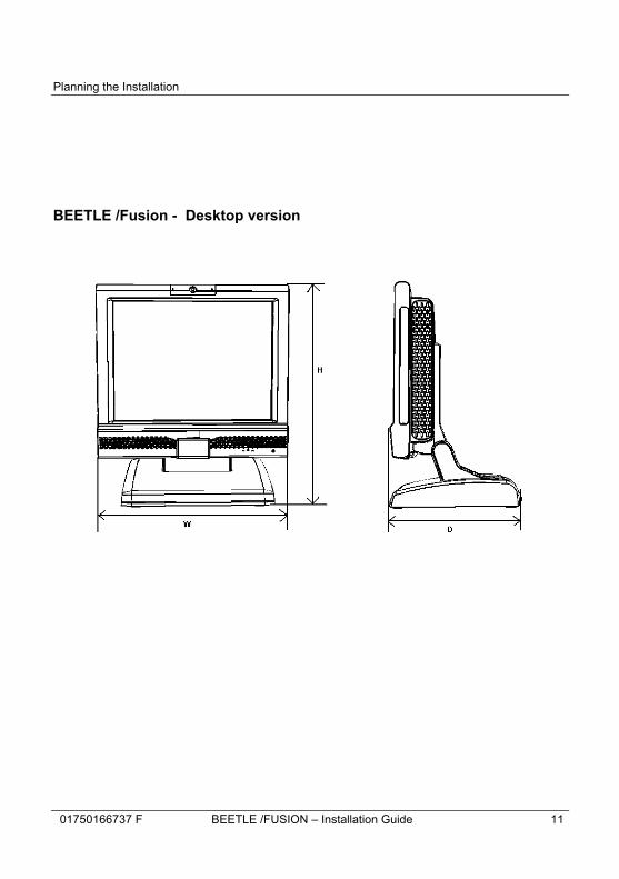
Device dimensions
All dimensions are specified in millimetres. The views of the systems are not drawn to scale.
15” Desktop
15”
Wall-mount
12.1”
Desktop
12.1” Wall-
mount
18.5”
Desktop
18.5” Wall-
mount Width (W) 370 370 320 320 476 476 Height (H) 430 336 420 296 434 342 Depth (D) 265 96 265 96 265 96
All dimensions in mm
Planning the Installation
01750166737 F BEETLE /FUSION – Installation Guide 11
BEETLE /Fusion - Desktop version

Planning the Installation
12 BEETLE /FUSION – Installation Guide 01750166737 F
BEETLE /Fusion - Wall-mount version

Planning the Installation
01750166737 F BEETLE /FUSION – Installation Guide 13
Required operation space
Reservation of minimum space is required to ensure proper ventilation during the operation of the device. Reserve at least 50 mm of operation space from the side of the device to its nearest barrier / wall.
!
50 mm 50 mm
Wall
BEETLE /FUSION System

Planning the Installation
14 BEETLE /FUSION – Installation Guide 01750166737 F
Installation site requirements
When choosing the installation site, make sure that - the system is sheltered indoor - For configuration with IR touch, make sure that the touch panel is
not exposed to direct or reflected sunlight as it may cause the touch to malfunction. Please read the Operating Environment for IR Touch found in the Appendix.
- If this system is taken from a cold environment into the operating
room, moisture condensation may form. The system must be absolutely dry before being put into service; an acclimatization period of at least two hours must therefore be observed.
- No cascading of power cables
Desktop version
Please take note of the following points for the installation site for desktop version: - The installation area must be flat leveled. - The system needs to be installed on the table surface and not on
the floor. If necessary, appropriate arrangements must be made.

Planning the Installation
01750166737 F BEETLE /FUSION – Installation Guide 15
Wall mount version
Please take note of the following points for the installation site for wall mount version: - Plan the mounting location carefully as location such as walkway
areas, hallways areas or crowded areas are not recommended in order to reduce the risk that someone might accidentally walk into and damage the system.
- Ensure that all applicable building and electric codes and
accessibility requirements are followed. - The mounting area needs to have enough room for adequate
viewing and ventilation, as well as the access to an AC power outlet.
- The mounting method must be able to support the combined weight
of the system and the suspended weight of all the cables attached to the system.
- The system is to be mounted on a solid concrete or brick wall
with flat smooth surface.
If necessary, appropriate arrangements must be made.

Planning the Installation
16 BEETLE /FUSION – Installation Guide 01750166737 F
Determining the mounting height of the wall mount plate
The mounting height of the system should be appropriate and comfortable for the majority of the user.
Based on the recommendation of the ADA (American Disability Association), it is recommended that the highest point of the display should not exceed 1370mm height. It is also recommended that the system is approximately 122cm (48 in) from the floor to the center of the display when the user is in the standing position.
122 cm (48 in)
Floor

Planning the Installation
01750166737 F BEETLE /FUSION – Installation Guide 17
Fasteners Type
Below are the recommended fastener types to wall mount the system: Fischer universal plug (UX 6 x 50) (http://www.fischer.de) Recommended Screw for wall is Pan head self-tapping M5 x 55.
Drill Diameter: 6 mm Min Hole Depth: 60 mm Load per anchor for concrete: 60 kg (Safety factor accounted for) Load per anchor for Solid brick: 30 kg (Safety factor accounted for)
Thorsman wall plug (TP 6 x 30 ) (http://www.thorsman.com) Recommended Screw for wall is Pan head Wood Screw TGS-C3- 4.8 x 38L Drill Diameter: 6 mm Min Hole Depth: 40 mm Load per anchor for concrete: 40 kg Load per anchor for Solid brick: 30 kg Safety factor is 6
Planning the Installation
18 BEETLE /FUSION – Installation Guide 01750166737 F
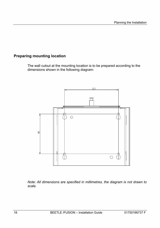
Preparing mounting location
The wall cutout at the mounting location is to be prepared according to the dimensions shown in the following diagram:
Note: All dimensions are specified in millimetres, the diagram is not drawn to scale.

Installation
01750166737 F BEETLE /FUSION – Installation Guide 19
Installation
This chapter describes the steps to be taken to install the system.
All dimensions are specified in millimetres. The diagrams are not drawn to scale.
Contact the person in charge of planning the installation to verify that all preparations have been performed completely and professionally and that none of the required power and data cables are missing.
Removing the packaging
• Remove the packing material of the system or the modules ordered.
• Dispose of the packaging which is no longer needed according to the regulations of your country.

Installation
20 BEETLE /FUSION – Installation Guide 01750166737 F
Installing desktop stand onto panel PC module
• After retrieving the panel PC and desktop stand from their respective packaging, lay them on the desk as illustrated in the picture below.
• Remove the stand covers and cable covers as indicated in the picture below to assess to cable routing path.
Cable cover #2
Stand cover #1
Stand cover #2
Cable cover #1
Desktop stand
Panel PC
Installation
01750166737 F BEETLE /FUSION – Installation Guide 21
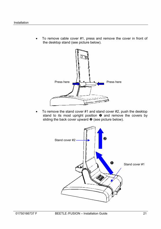
• To remove cable cover #1, press and remove the cover in front of the desktop stand (see picture below).
• To remove the stand cover #1 and stand cover #2, push the desktop stand to its most upright position � and remove the covers by sliding the back cover upward � (see picture below).
Press here Press here
�
� Stand cover #2
Stand cover #1

Installation
22 BEETLE /FUSION – Installation Guide 01750166737 F
• Unlock the cable clamp at the back of the desktop stand (see picture below).
• Route the cables through the desktop stand to the I/O panel of the panel PC, one cable at a time (see picture below).
unlock cable clamp
cables

Installation
01750166737 F BEETLE /FUSION – Installation Guide 23
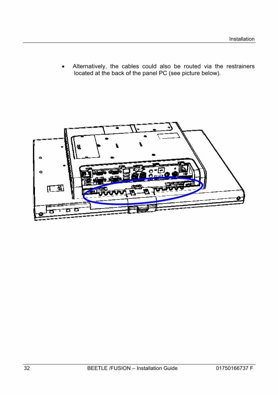
• Alternatively, the cables could also be routed via the restrainers located at he back of the panel PC (see picture below).

Installation
24 BEETLE /FUSION – Installation Guide 01750166737 F
• Ensure that the connectors are secured with their latch or screws.
• Install cable cover #1 (see picture below).
• Lift up the Panel PC and hook it on the desktop stand (see picture below).
Cable cover #1
Hook

Installation
01750166737 F BEETLE /FUSION – Installation Guide 25
• Fasten the 4 screws to secure the Panel PC to the desktop stand and dress the cables neatly in single file through the cable clamp (see picture below).
4x screws
Cable clamp

Installation
26 BEETLE /FUSION – Installation Guide 01750166737 F
• Lock the cable clamp to secure the cables (see picture below).
cable clamp
Installation
01750166737 F BEETLE /FUSION – Installation Guide 27
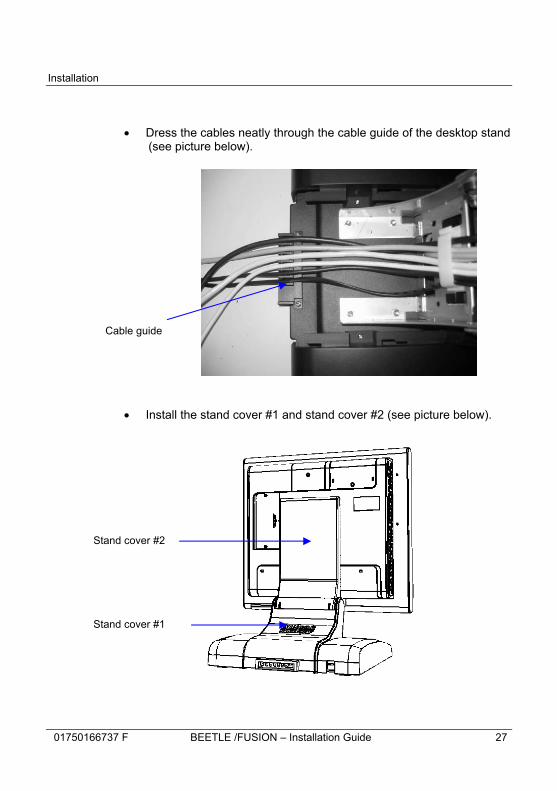
• Dress the cables neatly through the cable guide of the desktop stand (see picture below).
• Install the stand cover #1 and stand cover #2 (see picture below).
Stand cover #2
Stand cover #1
Cable guide
Installation
28 BEETLE /FUSION – Installation Guide 01750166737 F
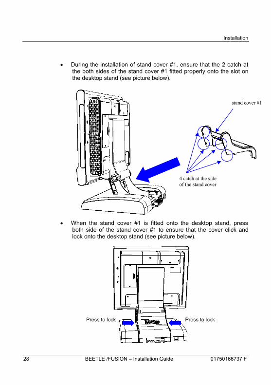
• During the installation of stand cover #1, ensure that the 2 catch at the both sides of the stand cover #1 fitted properly onto the slot on the desktop stand (see picture below).
• When the stand cover #1 is fitted onto the desktop stand, press both side of the stand cover #1 to ensure that the cover click and lock onto the desktop stand (see picture below).
4 catch at the side of the stand cover
stand cover #1
Press to lock Press to lock

Installation
01750166737 F BEETLE /FUSION – Installation Guide 29
• Tilt the panel PC back fully and install the cable cover #2 (see picture below).
• Ensure that the catch of the cable cover #2 is fitted onto the slot.
Cable cover #2

Installation
30 BEETLE /FUSION – Installation Guide 01750166737 F
Installing desktop stand-2 onto panel PC module
• After retrieving the panel PC and desktop stand from their respective packaging, lay them on the desk as illustrated in the picture below.
• To remove the stand cover #1, push the desktop stand to its most upright position � and remove by sliding it outward (see picture below).
�
Stand cover #1
Desktop stand
Panel PC
Installation
01750166737 F BEETLE /FUSION – Installation Guide 31
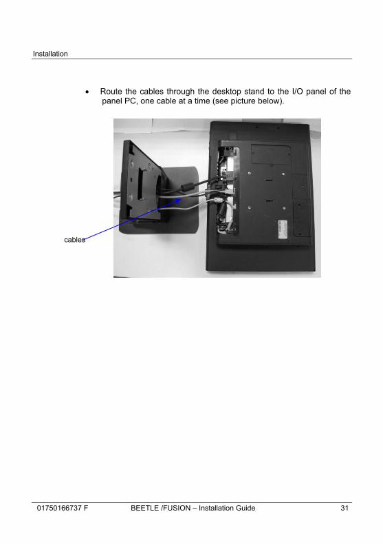
• Route the cables through the desktop stand to the I/O panel of the panel PC, one cable at a time (see picture below).
cables
Installation
32 BEETLE /FUSION – Installation Guide 01750166737 F
• Alternatively, the cables could also be routed via the restrainers located at the back of the panel PC (see picture below).

Installation
01750166737 F BEETLE /FUSION – Installation Guide 33
• Ensure that the connectors are secured with their latch or screws.
• Remove the indicated part of cable cover #1 by cutting the connecting tabs with scissors and bend the part to remove it (see picture below).
• Slot the cable cover #1 onto the back of the panel PC as shown above.
Cable cover #1
Cut connecting tabs

Installation
34 BEETLE /FUSION – Installation Guide 01750166737 F
• Lift up the Panel PC and hook it on the desktop stand (see picture below).
•
•
•
•
•
•
• Fasten the 2 panel fasteners � clockwise with Philip screwdriver to secure the Panel PC to the desktop stand and dress the cable neatly. Install the stand cover #1 by sliding it back into place � (see picture below).
2x screws
�
�
Hooks
Hook these 2 slots onto the hooks on the stand

Installation
01750166737 F BEETLE /FUSION – Installation Guide 35
Installing RAM onto panel PC module
• Remove the screws to access the RAM slot PC (see picture below).
remove screw

Installation
36 BEETLE /FUSION – Installation Guide 01750166737 F
• Insert the RAM module into the RAM slot and make sure it is engaged properly on the slot (see picture below).
• Close the cover and tighten the screws.
RAM slot
Ensure that the RAM module is inserted in this orientation
Installation
01750166737 F BEETLE /FUSION – Installation Guide 37
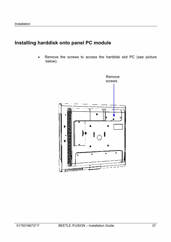
Installing harddisk onto panel PC module
• Remove the screws to access the harddisk slot PC (see picture
below).
Remove screws

Installation
38 BEETLE /FUSION – Installation Guide 01750166737 F
• Attach the 2 rail guides onto the harddisk. Ensure that the 2 guide rails are snapped onto the harddisk in the orientation shown in the picture below.

Installation
01750166737 F BEETLE /FUSION – Installation Guide 39
• Insert the harddisk assy into the harddisk slot and make sure it is engaged properly on the slot (see picture below).
• Close the cover and tighten the screws.
Harddisk slot
Ensure that the harddisk is inserted in this orientation
Installation
40 BEETLE /FUSION – Installation Guide 01750166737 F
Connecting the power cord
Ensure that the AC power point is switched off before inserting the specified power cord into the AC power point.
To connect the system to the power source, plug the connector of the power adapter into the power connector at the rear of the system.
Desktop version • Refer to page 16 to 19 for the steps to connect the power cord to the
desktop version
!

Installation
01750166737 F BEETLE /FUSION – Installation Guide 41
Wall mount version • Place the system on a flat surface and make sure that the display
screen is protected against rough surface to prevent damage on the screen especially when a touch panel has been installed (see picture below).
• Slide the I/O shield cover to the right to unlatch (1) before you slide downward to remove the cover (2) in order to access the I/O of the system (see picture below).
(2) Slide open the cover
(1) Slide cover to the right

Installation
42 BEETLE /FUSION – Installation Guide 01750166737 F
• Plug the connector of the power adaptor onto the system (see picture below).
• Connect all the required peripherals and network port into the I/O
ports of the system.
• Re-install the I/O shield covers back to the system.
• Plug the power plug into the socket outlet.
• The socket-outlet is to be installed near the device to ensure easy accessibility to the plug.
Power adapter connector

Installation
01750166737 F BEETLE /FUSION – Installation Guide 43
Installation of wall mount unit
IMPORTANT: Ensure that the wall mount plate must be installed by a professional and qualified installer who is familiar with the building construction methods and the electrical code that are govern by the local laws on the public access areas. Use only Wincor Nixdorf wall mount plate.
!
wall mount front plate
wall mount back plate
Wall

Installation
44 BEETLE /FUSION – Installation Guide 01750166737 F
Mounting wall mount back plate onto the wall
• Prepare the mounting points penetrating from the wall according to the dimension of the mounting holes on the base of the system.
• When the system is mounted onto the wall, ensure that the wall
mount back plate must be attached permanently and securely to prevent the system from falling and damaging if it is knocked, bumped or otherwise abused. Failing to do so may cause injury to others.
• Use the provided wall plugs to attach the wall mount back plate
onto the concrete wall.
• Check and ensure that the wall mount back plate is mounted squarely by using a bubble level.
• After installation, ensure that the screw heads are flushed or
below the outer surface of the wall mount back plate.
• Ensure that the wall mount back plate is firmly and securely attached to the wall.

Installation
01750166737 F BEETLE /FUSION – Installation Guide 45
Mounting wall mount front plate onto the system
o Align the 4 mounting holes of the wall mount front plate onto the mounting holes of panel PC.
o Secure the wall mount front plate onto the panel PC using the
fasteners provided in the wall mount kit.
Installation
46 BEETLE /FUSION – Installation Guide 01750166737 F
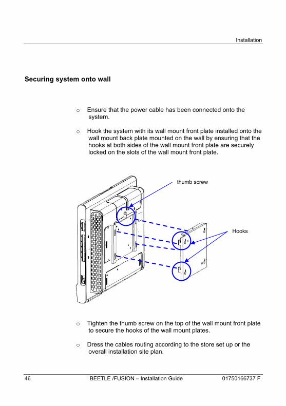
Securing system onto wall
o Ensure that the power cable has been connected onto the system.
o Hook the system with its wall mount front plate installed onto the
wall mount back plate mounted on the wall by ensuring that the hooks at both sides of the wall mount front plate are securely locked on the slots of the wall mount front plate.
o Tighten the thumb screw on the top of the wall mount front plate to secure the hooks of the wall mount plates.
o Dress the cables routing according to the store set up or the
overall installation site plan.
Hooks
thumb screw

Appendix
01750166737 F BEETLE /FUSION – Installation Guide 47
Appendix
Technical Data for BEETLE /Fusion 12
Wall mount Desktop Dimensions
Height 296 mm 420 mm Depth 96 mm 265 mm Width 320 mm 320 mm
Weight of device 6.3 kg 9.0 kg Climatic category
Operating IEC 721-3-3 class 3K3+ 5° to +40°C Transport IEC 721-3-2 class 2K2 -25° to +60°C Storage IEC 721-3-1 class 1K2 +5° to +40°C
Cat A & B Cat C Rated Input voltage 24V DC (nominal) 24V DC (nominal) Rated Input current 7.5A 4.16A
Certifications CE, FCC, CB, UL, TUV-GS, CCC, BSMI
CE, CB, CCC, BSMI
Remarks Resistive touch only
Appendix
48 BEETLE /FUSION – Installation Guide 01750166737 F
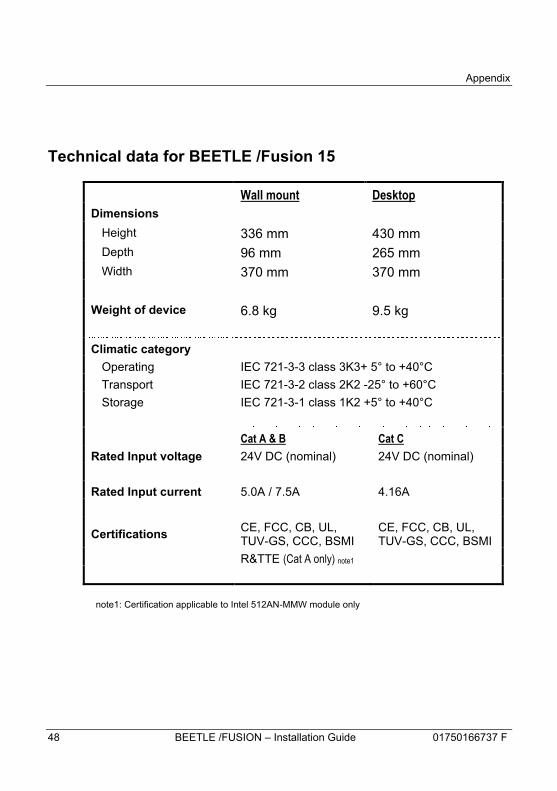
Technical data for BEETLE /Fusion 15
Wall mount Desktop Dimensions
Height 336 mm 430 mm Depth 96 mm 265 mm Width 370 mm 370 mm
Weight of device 6.8 kg 9.5 kg Climatic category
Operating IEC 721-3-3 class 3K3+ 5° to +40°C Transport IEC 721-3-2 class 2K2 -25° to +60°C Storage IEC 721-3-1 class 1K2 +5° to +40°C
Cat A & B Cat C Rated Input voltage 24V DC (nominal) 24V DC (nominal) Rated Input current 5.0A / 7.5A 4.16A
Certifications CE, FCC, CB, UL, TUV-GS, CCC, BSMI
CE, FCC, CB, UL, TUV-GS, CCC, BSMI
R&TTE (Cat A only) note1
note1: Certification applicable to Intel 512AN-MMW module only
Appendix
01750166737 F BEETLE /FUSION – Installation Guide 49
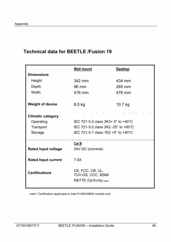
Technical data for BEETLE /Fusion 19
Wall mount Desktop Dimensions
Height 342 mm 434 mm Depth 96 mm 265 mm Width 476 mm 476 mm
Weight of device 8.0 kg 10.7 kg Climatic category
Operating IEC 721-3-3 class 3K3+ 5° to +40°C Transport IEC 721-3-2 class 2K2 -25° to +60°C Storage IEC 721-3-1 class 1K2 +5° to +40°C
Cat B Rated Input voltage 24V DC (nominal) Rated Input current 7.5A
Certifications CE, FCC, CB, UL, TUV-GS, CCC, BSMI
R&TTE (Cat B only) note1
note1: Certification applicable to Intel 512AN-MMW module only
Appendix
50 BEETLE /FUSION – Installation Guide 01750166737 F
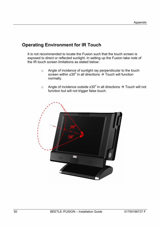
Operating Environment for IR Touch
It is not recommended to locate the Fusion such that the touch screen is exposed to direct or reflected sunlight. In setting up the Fusion take note of the IR touch screen limitations as stated below:
o Angle of incidence of sunlight ray perpendicular to the touch screen within ±30o in all directions à Touch will function normally.
o Angle of incidence outside ±30o in all directions à Touch will not function but will not trigger false touch.
30o
30o

Appendix
01750166737 F BEETLE /FUSION – Installation Guide 51
AC Power Adapter The AC power adapter used must be Wincor Nixdorf’s qualified and has to meet the following minimum requirements and industry standards:
Rated Input voltage 100 / 240 Vac Input Voltage range 90 to 264Vac Input Frequency range 47 to 63 Hz Rated Output voltage 24V ± 5%,
Rated Output current 4.17A (mini) if BEETLE /Fusion rating is 4.17A 5.0A (min) if BEETLE /Fusion rating is 5.0A 7.5A (min) if BEETLE /Fusion rating is 7.5A
Approvals & Certification UL Listed, TUV-GS, BSMI, CCC, CE

Appendix
52 BEETLE /FUSION – Installation Guide 01750166737 F
Power Cord Selection
If the power cord is not provided with the system, the user has to ensure that a certified power cord is used as required by the Safety Regulation of the country.
Countries Safety Approvals
USA UL
Canada CSA
Germany VDE
Japan PSE
Taiwan BSMI
China CCC
For other countries not mentioned in the above list, please check with the local authority.

Appendix
01750166737 F BEETLE /FUSION – Installation Guide 53
I/O connection ports
Refer to the diagram below for the available I/O connection ports:
USB (RJ45) note1
COM2 COM1
LAN COM4
Cashdrawer (RJ11)
COM6 (RJ45) note1
PS/2 COM3 VGA USB1 USB2
USB4 12V
USB3 24V
eSATA
Audio 5/12V Output
24V Input
Spk-Out (internal) note1
COM5 (touch) note1
note1: Proprietary interfaces, for Wincor specific devices only.

Published by Wincor Nixdorf Pte Ltd 2, Kallang Sector Singapore 349277 Part No.: 01750166737 F