SignalVu™ Vector Signal Analysis Software for ... dqpsk cck5.5m, cck11m 20 mhz 16 & 17 802.11g erp...
18
Vector Signal Analysis Software for Oscilloscopes SignalVu ™ Datasheet SignalVu vector signal analysis software combines the signal analysis engine of the RSA5000 and RSA6000 Series real-time spectrum analyzer with that of the industry's leading digital oscilloscopes, making it possible for designers to evaluate complex signals without an external down converter. You get the functionality of a vector signal analyzer, a spectrum analyzer, and the powerful trigger capabilities of a digital oscilloscope - all in a single package. You can use SignalVu with an MSO/DPO5000, DPO7000, or DPO/DSA/MSO70000 Series digital oscilloscope to easily validate wideband designs and characterize wideband spectral events. Whether your design validation needs include wideband radar, high data rate satellite links, wireless LAN, or frequency-hopping communications, SignalVu can speed your time-to-insight by showing you the time-variant behavior of these wideband signals. Key features Trigger Integrated RF signal analysis package lets you take full advantage of oscilloscope settings Pinpoint ™ triggering offers over 1400 combinations to address virtually any triggering situation Capture Direct observation of microwave signals without need of an external down converter All signals up to the analog bandwidth of oscilloscope are captured into memory Customize oscilloscope acquisition parameters for effective use of capture memory FastFrame segmented memory captures signal bursts without storing the signal's off time Supports RF, I and Q, and differential I and Q signals using the oscilloscope's 4 analog inputs Analyze Extensive time-correlated, multidomain displays connect problems in time, frequency, phase, and amplitude for quicker understanding of cause and effect when troubleshooting Power measurements and signal statistics help you characterize components and systems: ACLR, Multicarrier ACLR, Power vs. Time, CCDF, OBW/EBW, and Spur Search WLAN spectrum and modulation transmitter measurements based on IEEE 802.11 a/b/g/j/p/n/ac standards (Opts. SV23, SV24, and SV25) Simple and complete APCO Project 25 transmitter compliance testing and analysis for Phase 1 (C4FM) and Phase 2 (TDMA) (Opt. SV26) AM/FM/PM Modulation and Audio Measurements (Opt. SVA) for characterization of analog transmitters and audio signals Settling Time Measurements, Frequency, and Phase (Opt. SVT) for characterization of wideband frequency-agile oscillators Advanced Signal Analysis Suite (Opt. SVP) - Automated pulse measurements including rise time, pulse width, and pulse-to-pulse phase provide deep insight into pulse train behavior General Purpose Digital Modulation Analysis (Opt. SVM) provides vector signal analyzer functionality Flexible OFDM analysis (Opt. SVO) with support for 802.11a/g/j and WiMAX 802.16-2004 signals Frequency offset control for analyzing baseband signals with near- zero intermediate frequencies (IF) Tektronix OpenChoice ® makes for easy transfer to a variety of analysis programs such as Excel and Matlab Applications Wideband radar and pulsed RF signals Frequency agile communications Broadband satellite and microwave backhaul links Wireless LAN APCO P25 Wideband signal characterization SignalVu helps you easily validate wideband designs and characterize wideband spectral events using an MSO/DPO5000, DPO7000, or DPO/ DSA/MSO70000 Series digital oscilloscope. Users can easily switch between the SignalVu application and the oscilloscope's user interface to optimize the collection of wideband signals. www.tektronix.com 1
Transcript of SignalVu™ Vector Signal Analysis Software for ... dqpsk cck5.5m, cck11m 20 mhz 16 & 17 802.11g erp...

Vector Signal Analysis Software for OscilloscopesSignalVu™ Datasheet
SignalVu vector signal analysis software combines the signal analysisengine of the RSA5000 and RSA6000 Series real-time spectrum analyzerwith that of the industry's leading digital oscilloscopes, making it possiblefor designers to evaluate complex signals without an external downconverter. You get the functionality of a vector signal analyzer, a spectrumanalyzer, and the powerful trigger capabilities of a digital oscilloscope - allin a single package. You can use SignalVu with an MSO/DPO5000,DPO7000, or DPO/DSA/MSO70000 Series digital oscilloscope to easilyvalidate wideband designs and characterize wideband spectral events.Whether your design validation needs include wideband radar, high datarate satellite links, wireless LAN, or frequency-hopping communications,SignalVu can speed your time-to-insight by showing you the time-variantbehavior of these wideband signals.
Key features
TriggerIntegrated RF signal analysis package lets you take full advantageof oscilloscope settingsPinpoint™ triggering offers over 1400 combinations to addressvirtually any triggering situation
CaptureDirect observation of microwave signals without need of anexternal down converterAll signals up to the analog bandwidth of oscilloscope are capturedinto memoryCustomize oscilloscope acquisition parameters for effective use ofcapture memoryFastFrame segmented memory captures signal bursts withoutstoring the signal's off timeSupports RF, I and Q, and differential I and Q signals using theoscilloscope's 4 analog inputs
AnalyzeExtensive time-correlated, multidomain displays connect problemsin time, frequency, phase, and amplitude for quicker understandingof cause and effect when troubleshootingPower measurements and signal statistics help you characterizecomponents and systems: ACLR, Multicarrier ACLR, Power vs.Time, CCDF, OBW/EBW, and Spur SearchWLAN spectrum and modulation transmitter measurements basedon IEEE 802.11 a/b/g/j/p/n/ac standards (Opts. SV23, SV24, andSV25)Simple and complete APCO Project 25 transmitter compliancetesting and analysis for Phase 1 (C4FM) and Phase 2 (TDMA)(Opt. SV26)AM/FM/PM Modulation and Audio Measurements (Opt. SVA) forcharacterization of analog transmitters and audio signalsSettling Time Measurements, Frequency, and Phase (Opt. SVT)for characterization of wideband frequency-agile oscillatorsAdvanced Signal Analysis Suite (Opt. SVP) - Automated pulsemeasurements including rise time, pulse width, and pulse-to-pulsephase provide deep insight into pulse train behaviorGeneral Purpose Digital Modulation Analysis (Opt. SVM) providesvector signal analyzer functionalityFlexible OFDM analysis (Opt. SVO) with support for 802.11a/g/jand WiMAX 802.16-2004 signalsFrequency offset control for analyzing baseband signals with near-zero intermediate frequencies (IF)Tektronix OpenChoice® makes for easy transfer to a variety ofanalysis programs such as Excel and Matlab
Applications
Wideband radar and pulsed RF signals
Frequency agile communications
Broadband satellite and microwave backhaul links
Wireless LAN
APCO P25
Wideband signal characterizationSignalVu helps you easily validate wideband designs and characterizewideband spectral events using an MSO/DPO5000, DPO7000, or DPO/DSA/MSO70000 Series digital oscilloscope. Users can easily switchbetween the SignalVu application and the oscilloscope's user interface tooptimize the collection of wideband signals.
www.tektronix.com 1

TriggerSignalVu software works seamlessly with the oscilloscope allowing users toutilize all of its powerful triggering capabilities. The ability to trigger on time-and amplitude-varying events of interest is paramount in wideband systemdesign, debug, and validation. The Tektronix oscilloscopes' trigger systemsallow selection of virtually all trigger types on both A and B trigger eventswhether they be transition, state, time, or logic qualified triggers. Oncetriggered, SignalVu processes the acquisition for analysis in multipledomains.
Powerful oscilloscope triggers allow the user to capture only the relevantportion of wideband signals. Pinpoint trigger functions such as combining Aand B events with Edge with Holdoff can capture a pulse train during aspecific transmitter mode of operation.
CaptureCapture once - make multiple measurements without recapturing. Allsignals in an acquisition bandwidth are recorded into the oscilloscope'sdeep memory. Up to four channels can be captured simultaneously; eachof which can be independently analyzed by SignalVu software. Channelscan be RF, I and Q, or differential inputs. Users can also apply mathfunctions to the acquisition prior to analysis by SignalVu. Acquisitionlengths vary depending upon the selected capture bandwidth - up to 25 mscan be captured on a single channel with the MSO/DPO5000 Series, up to12.5 ms can be acquired on a single channel with the DPO7000 Series,and up to 2.5 ms can be captured on a single channel with the DPO/DSA/MSO70000 Series. Significantly longer capture times can be realized withlower oscilloscope sample rates.
Using the FastFrame segmented memory feature in SignalVu enables youto capture events of interest, such as low duty cycle pulsed signals, whileconserving acquisition memory. Using multiple trigger events, FastFramecaptures and stores short-duration, bursty signals and passes them toSignalVu vector signal analysis functions. Capturing thousands of frames ispossible, so long-term trends and changes in the bursty signal can beanalyzed.
Once captured into memory, SignalVu provides detailed analysis in multipledomains. The spectrogram display (left panel) shows the frequency of an800 MHz wide LFM pulse changing over time. By selecting the point in timein the spectrogram during the On time of the pulse, the chirp behavior canbe seen as it sweeps from low to high (lower right panel).
AnalyzeSignalVu vector signal analysis software utilizes the same analysiscapabilities found in the RSA5000 and RSA6000 Series real-time spectrumanalyzers. SignalVu advances productivity for engineers working oncomponents or in wideband RF system design, integration, andperformance verification, or operations engineers working in networks, orspectrum management. In addition to spectrum analysis, spectrogramsdisplay both frequency and amplitude changes over time. Time-correlatedmeasurements can be made across the frequency, phase, amplitude, andmodulation domains. This is ideal for signal analysis that includesfrequency hopping, pulse characteristics, modulation switching, settlingtime, bandwidth changes, and intermittent signals.
SignalVu can process RF, I and Q, and differential I and Q signals from anyone of the four available oscilloscope inputs. Math functions applied by theoscilloscope are also utilized by SignalVu allowing users to apply customfiltering prior to vector signal analysis.
The Microsoft Windows environment makes this multidomain analysis eveneasier with an unlimited number of analysis windows, all time-correlated, toprovide deeper insight into signal behavior. A user interface that adapts toyour preferences (keyboard, front panel, touch screen, and mouse) makeslearning SignalVu easy for both first-time users and experienced hands.
Datasheet
2 www.tektronix.com
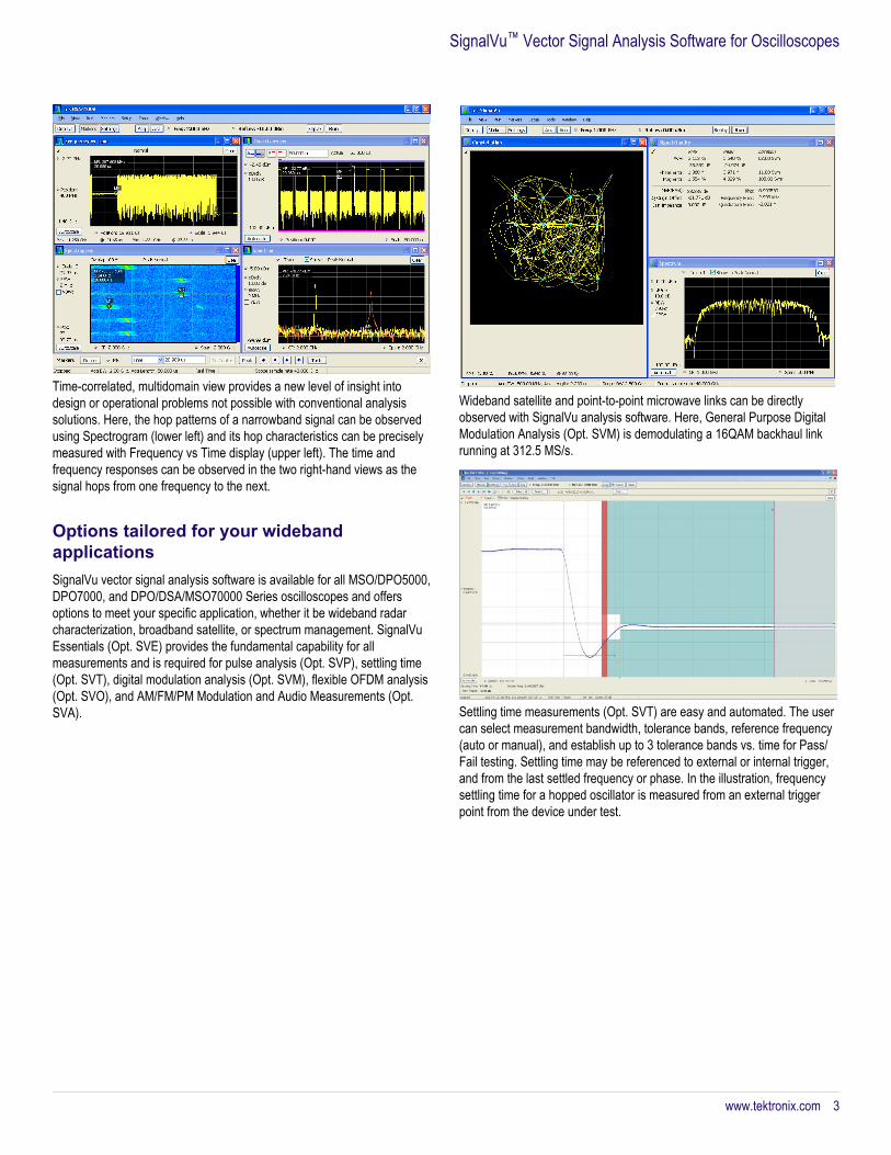
Time-correlated, multidomain view provides a new level of insight intodesign or operational problems not possible with conventional analysissolutions. Here, the hop patterns of a narrowband signal can be observedusing Spectrogram (lower left) and its hop characteristics can be preciselymeasured with Frequency vs Time display (upper left). The time andfrequency responses can be observed in the two right-hand views as thesignal hops from one frequency to the next.
Options tailored for your widebandapplicationsSignalVu vector signal analysis software is available for all MSO/DPO5000,DPO7000, and DPO/DSA/MSO70000 Series oscilloscopes and offersoptions to meet your specific application, whether it be wideband radarcharacterization, broadband satellite, or spectrum management. SignalVuEssentials (Opt. SVE) provides the fundamental capability for allmeasurements and is required for pulse analysis (Opt. SVP), settling time(Opt. SVT), digital modulation analysis (Opt. SVM), flexible OFDM analysis(Opt. SVO), and AM/FM/PM Modulation and Audio Measurements (Opt.SVA).
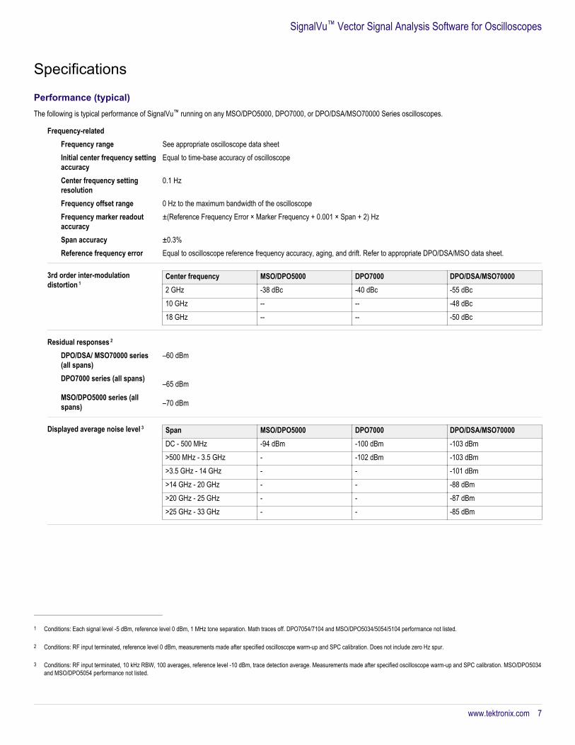
Wideband satellite and point-to-point microwave links can be directlyobserved with SignalVu analysis software. Here, General Purpose DigitalModulation Analysis (Opt. SVM) is demodulating a 16QAM backhaul linkrunning at 312.5 MS/s.
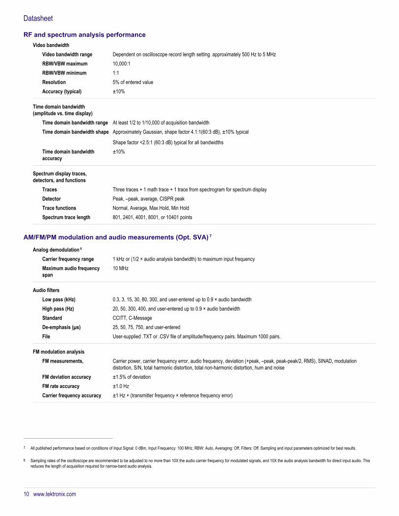
Settling time measurements (Opt. SVT) are easy and automated. The usercan select measurement bandwidth, tolerance bands, reference frequency(auto or manual), and establish up to 3 tolerance bands vs. time for Pass/Fail testing. Settling time may be referenced to external or internal trigger,and from the last settled frequency or phase. In the illustration, frequencysettling time for a hopped oscillator is measured from an external triggerpoint from the device under test.
SignalVu™ Vector Signal Analysis Software for Oscilloscopes
www.tektronix.com 3

WLAN transmitter testingWith the WLAN measurement options, you can perform standards-basedtransmitter measurements in the time, frequency, and modulation domains.
Option SV23 supports IEEE 802.11a, b, g, j and p signals
Option SV24 supports IEEE 802.11n 20 MHz and 40 MHz SISOsignals
Option SV25 supports IEEE 802.11ac 20/40/80/160 MHz SISO signals
The table below described the modulation formats and frequency bands ofIEEE 802.11 WLAN signals
Standard Std PHY Freqband(s)
Signal Modula-tionformats
Band-width(max)
802.11-2012 section
802.11b DSSS HR/DSSS
2.4 GHz DSSS/CCK1 -11 Mbps
DBSK,DQPSKCCK5.5M,CCK11M
20 MHz 16 & 17
802.11g ERP 2.4 GHz DSSS/CCK/PBCC1 -33 Mbps
BPSKDQPSK
20 MHz 17
802.11a OFDM 5 GHz OFDM 64 <54 Mbps
BPSKQPSK16QAM64QAM
20 MHz 18 802.11g 2.4 GHz 20 MHz 19 802.11j/p 5 GHz 5, 10,
20 MHz18
802.11n HT 2.4 GHz &5 GHz
OFDM 64,128 ≤150 Mbps
BPSKQPSK16QAM64QAM
20 ,40 MHz
20
802.11ac VHT 5 GHz OFDM 64,128, 256,512 ≤867 Mbps
BPSKQPSK16QAM64QAM256QAM
20, 40, 80,160 MHz
22
The Frequency Band (Freq Band(s)) provides the minimum requirement forthe bandwidth of the oscilloscope to use.
Inside SignalVu, the WLAN presets make the EVM, Constellation and SEMmeasurements push-button. The WLAN RF transmitter measurements aredefined by the IEEE 802.11- 2012 revision of the standard and listed belowwith the reference to the section and the limit to reach.
Datasheet
4 www.tektronix.com

Easy analysis of WLAN 802.11ac transmitter with a WLAN preset that provides spectralemission mask, constellation diagram, and decoded burst information.
Measurement functionsSpectrum analyzer measurements(Opt. SVE)
Channel Power, Adjacent ChannelPower, Multicarrier Adjacent ChannelPower/Leakage Ratio, OccupiedBandwidth, xdB Down, dBm/Hz Marker,dBc/Hz Marker
Time domain and statisticalmeasurements(Opt. SVE)
RF IQ vs. Time, Amplitude vs. Time,Power vs. Time, Frequency vs. Time,Phase vs. Time, CCDF, Peak-to-Average Ratio, Amplitude, Frequency,and Phase Modulation Analysis
Spur search measurements(Opt. SVE)
Up to 20 ranges, user-selected detectors(peak, average, CISPR peak), filters(RBW, CISPR, MIL) and VBW in eachrange. Linear or Log frequency scale.Measurements and violations inabsolute power or relative to a carrier.Up to 999 violations identified in tabularform for export in CSV format
WLAN 802.11a/b/g/j/p measurementapplication (Opt. SV23)
All of the RF transmitter measurementsas defined in the IEEE standard, and awide range of additional scalarmeasurements such as CarrierFrequency error, Symbol Timing error,Average/peak burst power, IQ OriginOffset, RMS/Peak EVM, and analysisdisplays, such as EVM and Phase/Magnitude Error vs time/frequency or vssymbols/ subcarriers, as well as packetheader decoded information and symboltable.Option SV23 requires Option SVEOption SV24 requires Option SV23Option SV25 requires Option SV24
WLAN 802.11n measurementapplication (Opt. SV24)WLAN 802.11ac measurementapplication (Opt. SV25)
APCO P25 compliance testing andanalysis application (Opt. SV26)
Complete set of push-buttonTIA-102 standard-based transmittermeasurements with pass/fail resultsincluding ACPR, transmitter power andencoder attack times, transmitterthroughput delay, frequency deviation,modulation fidelity, symbol rateaccuracy, and transient frequencybehavior, as well as HCPM transmitterlogical channel peak ACPR, off slotpower, power envelope, and timealignment.Option SV26 requires Option SVE
AM/FM/PM modulation and audiomeasurements(Opt. SVA)
Carrier Power, Frequency Error,Modulation Frequency, ModulationParameters (±peak, peak-peak/2, RMS),SINAD, Modulation Distortion, S/N,THD, TNHD, Hum and Noise
Settling time (frequency and phase)(Opt. SVT)
Measured Frequency, Settling Timefrom last settled frequency, SettlingTime from last settled phase, SettlingTime from Trigger. Automatic or manualreference frequency selection. User-adjustable measurement bandwidth,averaging, and smoothing. Pass/FailMask Testing with 3 user-settable zones
SignalVu™ Vector Signal Analysis Software for Oscilloscopes
www.tektronix.com 5

Advanced signal analysis (Opt.SVP)
Average On Power, Peak Power,Average Transmitted Power, PulseWidth, Rise Time, Fall Time, RepetitionInterval (seconds), Repetition Interval(Hz), Duty Factor (%), Duty Factor(ratio), Ripple (dB), Ripple (%), Droop(dB), Droop (%), Overshoot (dB),Overshoot (%), Pulse-Pulse FrequencyDifference, Pulse-Pulse PhaseDifference, RMS Frequency Error, MaxFrequency Error, RMS Phase Error, MaxPhase Error, Frequency Deviation,Phase Deviation, Impulse Response(dB), Impulse Response (time), TimeStamp
Flexible OFDM analysis(Opt. SVO)
OFDM analysis with support for WLAN802.11a/g/j and WiMAX 802.16-2004.Constellation, Scalar MeasurementSummary, EVM or Power vs. Carrier,Symbol Table (Binary or Hexadecimal)
General purpose digital modulationanalysis(Opt. SVM)
Error Vector Magnitude (EVM) (RMS,Peak, EVM vs. Time), Modulation ErrorRatio (MER), Magnitude Error (RMS,Peak, Mag Error vs. Time), Phase Error(RMS, Peak, Phase Error vs. Time),Origin Offset, Frequency Error, GainImbalance, Quadrature Error, Rho,Constellation, Symbol Table.FSK only: Frequency Deviation, SymbolTiming Error
The Advanced Signal Analysis package (Opt. SVP) provides 27 individualmeasurements to automatically characterize long pulse trains. An 800 MHzwide LFM chirp centered at 18 GHz is seen here with measurements forpulses 7 through 18 (upper right). The shape of the pulse can be seen inthe Amplitude vs. Time plot shown in the upper left. Detailed views of pulse#8's frequency deviation and parabolic phase trajectory are shown in thelower two views.
Settling time measurements (Opt. SVT) are easy and automated. The usercan select measurement bandwidth, tolerance bands, reference frequency(auto or manual), and establish up to 3 tolerance bands vs. time for Pass/Fail testing. Settling time may be referenced to external or internal trigger,and from the last settled frequency or phase. In the illustration, frequencysettling time for a hopped oscillator is measured from an external triggerpoint from the device under test.
Datasheet
6 www.tektronix.com
Specifications
Performance (typical)The following is typical performance of SignalVu™ running on any MSO/DPO5000, DPO7000, or DPO/DSA/MSO70000 Series oscilloscopes.
Frequency-relatedFrequency range See appropriate oscilloscope data sheetInitial center frequency settingaccuracy
Equal to time-base accuracy of oscilloscope
Center frequency settingresolution
0.1 Hz
Frequency offset range 0 Hz to the maximum bandwidth of the oscilloscopeFrequency marker readoutaccuracy
±(Reference Frequency Error × Marker Frequency + 0.001 × Span + 2) Hz
Span accuracy ±0.3%Reference frequency error Equal to oscilloscope reference frequency accuracy, aging, and drift. Refer to appropriate DPO/DSA/MSO data sheet.
3rd order inter-modulationdistortion 1
Center frequency MSO/DPO5000 DPO7000 DPO/DSA/MSO700002 GHz -38 dBc -40 dBc -55 dBc10 GHz -- -- -48 dBc18 GHz -- -- -50 dBc
Residual responses 2
DPO/DSA/ MSO70000 series(all spans)
–60 dBm
DPO7000 series (all spans)–65 dBm
MSO/DPO5000 series (allspans) –70 dBm
Displayed average noise level 3 Span MSO/DPO5000 DPO7000 DPO/DSA/MSO70000DC - 500 MHz -94 dBm -100 dBm -103 dBm>500 MHz - 3.5 GHz - -102 dBm -103 dBm>3.5 GHz - 14 GHz - - -101 dBm>14 GHz - 20 GHz - - -88 dBm>20 GHz - 25 GHz - - -87 dBm>25 GHz - 33 GHz - - -85 dBm
1 Conditions: Each signal level -5 dBm, reference level 0 dBm, 1 MHz tone separation. Math traces off. DPO7054/7104 and MSO/DPO5034/5054/5104 performance not listed.
2 Conditions: RF input terminated, reference level 0 dBm, measurements made after specified oscilloscope warm-up and SPC calibration. Does not include zero Hz spur.
3 Conditions: RF input terminated, 10 kHz RBW, 100 averages, reference level -10 dBm, trace detection average. Measurements made after specified oscilloscope warm-up and SPC calibration. MSO/DPO5034and MSO/DPO5054 performance not listed.
SignalVu™ Vector Signal Analysis Software for Oscilloscopes
www.tektronix.com 7

Input-relatedNumber of inputs 4 4 Input signal types RF, I and Q (single ended), I and Q (differential)Maximum input level +26 dBm for 50 Ω input (5 VRMS)
Trigger-relatedTrigger modes Free Run and Triggered. Trigger sensitivity and characteristics can be found in the appropriate oscilloscope data sheet.
Acquisition-related SignalVu provides long acquisitions of waveform captures with high time and frequency resolution. Maximum acquisition time willvary based on the oscilloscope's available memory and analog bandwidth. The following table highlights each model's single-channel capabilities given its maximum available memory configuration.
Model 5 Max span Max acquisitiontime at maxsample rate
Min RBW at maxsample rate
Min IQ timeresolution
Max number ofFastFrames 6
DPO/DSA73304D 33 GHz 2.5 ms 1.2 kHz 20 ps 65,535 DPO/DSA72504D 25 GHzDPO/DSA/MSO72004C
20 GHz
DPO/DSA/MSO71604C
16 GHz
DPO/DSA/MSO71254C
12.5 GHz
DPO/DSA/MSO70804C
8 GHz 5 ms 600 Hz 80 ps
DPO/DSA/MSO70604C
6 GHz
DPO/DSA/MSO70404C
4 GHz
DPO7354C 3.5 GHz 12.5 ms 300 Hz 50 psDPO7254C 2.5 GHzDPO7104C 1 GHz 100 psDPO7054C 500 MHzMSO/DPO5204 2 GHz 25 ms 100 Hz 200 psMSO/DPO5104 1 GHzMSO/DPO5054 500 MHz 400 psMSO/DPO5034 350 MHz
4 SignalVu can process acquisitions from any one of the oscilloscope channels. Users can also apply custom math and filter functions to each of the oscilloscope's acquisition channels. The resulting Mathchannel can then be selected by SignalVu for signal processing.
5 With maximum available record length option and maximum sample rate.
6 Maximum number of frames available will depend upon the oscilloscope's record length, sample rate, and the acquisition length settings.
Datasheet
Performance (typical)
8 www.tektronix.com

Analysis-relatedFrequency (Opt. SVE) Spectrum (Amplitude vs. Linear or Log Frequency)
Spectrogram (Amplitude vs. Frequency over Time)
Spurious (Amplitude vs. Linear or Log Frequency)Time and statistics (Opt. SVE) Amplitude vs. Time
Frequency vs. Time
Phase vs. Time
Amplitude Modulation vs. Time
Frequency Modulation vs. Time
Phase Modulation vs. Time
RF IQ vs. Time
Time Overview
CCDF
Peak-to-Average RatioSettling time, frequency, andphase (Opt. SVT)
Frequency Settling vs. Time
Phase Settling vs. TimeAdvanced measurementssuite (Opt. SVP)
Pulse results Table
Pulse trace (Selectable by pulse number)
Pulse statistics (Trend of pulse results, FFT of trend, and histogram)Digital demod (Opt. SVM) Constellation diagram
EVM vs. Time
Symbol table (binary or hexadecimal)
Magnitude and Phase Error vs. Time, and Signal Quality
Demodulated IQ vs. Time
Eye diagram
Trellis diagram
Frequency Deviation vs. TimeFlexible OFDM (Opt. SVO) EVM vs. Symbol, vs. Subcarrier Subcarrier Power vs. Symbol, vs. Subcarrier Subcarrier constellation Symbol data table Mag Error
vs. Symbol, vs. Subcarrier Phase Error vs. Symbol, vs. Subcarrier Channel frequency responseSupported file formats SignalVu can recall saved acquisitions from MSO/DPO5000, DPO7000, DPO/DSA/MSO70000, RSA5000, and RSA6000 Series
instruments. Both WFM and TIQ file extensions can be recalled for postprocessing by SignalVu.
RF and spectrum analysis performance
Resolution bandwidthResolution bandwidth(spectrum analysis)
1, 2, 3, 5 sequence, auto-coupled, or user selected (arbitrary)
Resolution bandwidth shape Approximately Gaussian, shape factor 4.1:1 (60:3 dB) ±10%, typicalResolution bandwidthaccuracy
±1% (auto-coupled RBW mode)
Alternative resolutionbandwidth types
Kaiser window (RBW), –6 dB Mil, CISPR, Blackman-Harris 4B window, Uniform window (none), flat-top window (CW ampl.),Hanning window
SignalVu™ Vector Signal Analysis Software for Oscilloscopes
Performance (typical)
www.tektronix.com 9
Video bandwidthVideo bandwidth range Dependent on oscilloscope record length setting. approximately 500 Hz to 5 MHzRBW/VBW maximum 10,000:1 RBW/VBW minimum 1:1 Resolution 5% of entered valueAccuracy (typical) ±10%
Time domain bandwidth(amplitude vs. time display)
Time domain bandwidth range At least 1/2 to 1/10,000 of acquisition bandwidthTime domain bandwidth shape Approximately Gaussian, shape factor 4.1:1(60:3 dB), ±10% typical
Shape factor <2.5:1 (60:3 dB) typical for all bandwidthsTime domain bandwidthaccuracy
±10%
Spectrum display traces,detectors, and functions
Traces Three traces + 1 math trace + 1 trace from spectrogram for spectrum displayDetector Peak, –peak, average, CISPR peakTrace functions Normal, Average, Max Hold, Min HoldSpectrum trace length 801, 2401, 4001, 8001, or 10401 points
AM/FM/PM modulation and audio measurements (Opt. SVA) 7
Analog demodulation 8
Carrier frequency range 1 kHz or (1/2 × audio analysis bandwidth) to maximum input frequencyMaximum audio frequencyspan
10 MHz
Audio filtersLow pass (kHz) 0.3, 3, 15, 30, 80, 300, and user-entered up to 0.9 × audio bandwidthHigh pass (Hz) 20, 50, 300, 400, and user-entered up to 0.9 × audio bandwidthStandard CCITT, C-MessageDe-emphasis (µs) 25, 50, 75, 750, and user-enteredFile User-supplied .TXT or .CSV file of amplitude/frequency pairs. Maximum 1000 pairs.
FM modulation analysisFM measurements, Carrier power, carrier frequency error, audio frequency, deviation (+peak, –peak, peak-peak/2, RMS), SINAD, modulation
distortion, S/N, total harmonic distortion, total non-harmonic distortion, hum and noiseFM deviation accuracy ±1.5% of deviationFM rate accuracy ±1.0 HzCarrier frequency accuracy ±1 Hz + (transmitter frequency × reference frequency error)
7 All published performance based on conditions of Input Signal: 0 dBm, Input Frequency: 100 MHz, RBW: Auto, Averaging: Off, Filters: Off. Sampling and input parameters optimized for best results.
8 Sampling rates of the oscilloscope are recommended to be adjusted to no more than 10X the audio carrier frequency for modulated signals, and 10X the audio analysis bandwidth for direct input audio. Thisreduces the length of acquisition required for narrow-band audio analysis.
Datasheet
RF and spectrum analysis performance
10 www.tektronix.com

Residuals (FM) (rate: 1 kHz to10 kHz, deviation: 5 kHz)
THD 0.2% (MSO/DPO7000, 70000 Series)
1.0% (MSO/DPO5000 Series)SINAD 44 dB (MSO/DPO7000, 70000 Series)
38 dB (MSO/DPO5000 Series)
AM modulation analysisAM measurements Carrier power, audio frequency, modulation depth (+peak, –peak, peak-peak/2), RMS, SINAD, modulation distortion, S/N, total
harmonic distortion, total non-harmonic distortion, hum and noiseAM depth accuracy (rate:1 kHz, depth: 50%)
±1% + 0.01 × measured value
AM rate accuracy (rate: 1 kHz,depth: 50%)
±1.0 Hz
Residuals (AM)THD 0.3% (MSO/DPO7000, 70000 Series)
1.0% (MSO/DPO5000 Series)SINAD 48 dB (MSO/DPO7000, 70000 Series)
43 dB (MSO/DPO5000 Series)
PM modulation analysisPM measurement Carrier power, carrier frequency error, audio frequency, deviation (+peak, –peak, peak-peak/2, RMS), SINAD, modulation
distortion, S/N, total harmonic distortion, total non-harmonic distortion, hum and noisePM deviation accuracy (rate:1 kHz, deviation: 0.628 rad)
±100% × (0.01 + (rate / 1 MHz))
PM rate accuracy (rate: 1 kHz,deviation: 0.628 rad)
±1 Hz
Residuals (PM)THD 0.1% (MSO/DPO7000, 70000 Series)
0.5% (MSO/DPO5000 Series)SINAD 48 dB (MSO/DPO7000, 70000 Series)
43 dB (MSO/DPO5000 Series)
Direct audio inputAudio measurements Signal power, audio frequency (+peak, –peak, peak-peak/2, RMS), SINAD, modulation distortion, S/N, total harmonic distortion,
total non-harmonic distortion, hum and noiseDirect input frequency range(for audio measurements only)
1 Hz to 10 MHz
Maximum audio frequencyspan
10 MHz
Audio frequency accuracy ±1 Hz
Residuals (PM)THD 1.5%SINAD 38 dB
SignalVu™ Vector Signal Analysis Software for Oscilloscopes
AM/FM/PM modulation and audio measurements (Opt. SVA)
www.tektronix.com 11

Minimum audio analysisbandwidth and RBW vs.oscilloscope memory and samplerate
Model Sample rate: 1 GS/s Sample rate: maximumStandard memory Maximum memory Standard memory Maximum memoryMin. Aud.BW
RBW (Auto) Min. Aud.BW
RBW (Auto) Min. Aud.BW
RBW (Auto) Min. Aud.BW
RBW (Auto)
MSO/ DPO5034 MSO/DPO5054
200 kHz 400 Hz 20 kHz 40 Hz 1 MHz 2 kHz 100 kHz 200 hz
MSO/DPO5104 MSO/DPO5204
100 kHz 200 Hz 10 kHz 20 hz 1 MHz 2 kHz 100 kHz 200 Hz
DPO7000
50 kHz 100 Hz 50 kHz 100 Hz 2 MHz 4 kHz 2 MHz 4 kHz
DPO/DSA/MSO70000 ≥12.5 GHz BW
200 kHz 400 Hz 10 kHz 20 Hz not recom-mended
>4 kHz 1 MHz 2 kHz
DPO/DSA/MSO70000 <12.5 GHz BW
200 kHz 400 Hz 20 kHz 40 Hz not recom-mended
>4 kHz 500 kHz 1 kHz
Settling time, frequency, and phase (Opt. SVT) 9
Settled frequency uncertainty,Measurement frequency:1 GHz
Averages Frequency uncertainty at stated measurement bandwidth1 GHz 100 MHz 10 MHz 1 MHz
Single measurement 20 kHz 2 kHz 500 Hz 100 Hz100 averages 10 kHz 500 Hz 200 Hz 50 Hz1000 averages 2 kHz 200 Hz 50 Hz 10 Hz
Measurement frequency:9 GHz
Averages Frequency uncertainty at stated measurement bandwidth1 GHz 100 MHz 10 MHz 1 MHz
Single Measurement 20 kHz 5 kHz 2 kHz 200 Hz100 Averages 10 kHz 2 kHz 500 Hz 50 Hz1000 Averages 2 kHz 500 Hz 200 Hz 20 Hz
9 Settled Frequency or Phase at the measurement frequency. Measured signal level > -20 dBm, Attenuator: Auto.
Datasheet
AM/FM/PM modulation and audio measurements (Opt. SVA)
12 www.tektronix.com
Settled phase uncertainty,Measurement frequency:1 GHz
Averages Phase uncertainty at stated measurement bandwidth1 GHz 100 MHz 10 MHz 1 MHz
Single measurement 2° 2° 2° 2°100 averages 0.5° 0.5° 0.5° 0.5°1000 averages 0.2° 0.2° 0.2° 0.2°
Measurement frequency:9 GHz
Averages Phase uncertainty at stated measurement bandwidth1 GHz 100 MHz 10 MHz 1 MHz
Single measurement 5° 5° 5° 5°100 averages 2° 2° 2° 2°1000 averages 0.5° 0.5° 0.5° 0.5°
Advanced measurement suite (Opt. SVP)
General characteristicsMeasurements Average On Power, Peak Power, Average Transmitted Power, Pulse Width, Rise Time, Fall Time, Repetition Interval (seconds),
Repetition Interval (Hz), Duty Factor (%), Duty Factor (ratio), Ripple (dB), Ripple (%), Droop (dB), Droop (%), Overshoot (dB),Overshoot (%), Pulse-Pulse Frequency Difference, Pulse-Pulse Phase Difference, RMS Frequency Error, Max Frequency Error,RMS Phase Error, Max Phase Error, Frequency Deviation, Phase Deviation, Impulse Response (dB), Impulse Response (time),Time Stamp
Number of pulses 1 to 10,000 System rise time (typical) Equal to oscilloscope rise time
Minimum pulse width fordetection 10
Model Minimum PWDPO/DSA72004BMSO72004
400 ps
DPO/DSA71604BMSO71604
500 ps
DPO/DSA71254BMSO71254
640 ps
DPO/DSA70804BMSO70804
1 ns
DPO/DSA70604BMSO70604
1.3 ns
DPO/DSA70404BMSO70404
2 ns
DPO7354 2.25 nsDPO7254 3 nsDPO7104 8 nsDPO7054 16 nsMSO/DPO5204 4 nsMSO/DPO5104 8 nsMSO/DPO5054 16 nsMSO/DPO5034 25 ns
10 Conditions: Approximately equal to 10/(IQ sampling rate). IQ sampling rate is the final sample rate after digital down conversion from the oscilloscope. Pulse measurement filter set to max bandwidth.
SignalVu™ Vector Signal Analysis Software for Oscilloscopes
Settling time, frequency, and phase (Opt. SVT)
www.tektronix.com 13

Pulse measurement accuracy(typical) 11
Average on power ±0.3 dB + Absolute Amplitude Accuracy of oscilloscopeAverage transmitted power ±0.4 dB + Absolute Amplitude Accuracy of oscilloscopePeak power ±0.4 dB + Absolute Amplitude Accuracy of oscilloscopePulse width ±(3% of reading + 0.5 × sample period)Pulse repetition rate ±(3% of reading + 0.5 × sample period)
Digital modulation analysis (Opt. SVM)
Modulation formats π/2DBPSK, BPSK, SBPSK, QPSK, DQPSK, π/4DQPSK, D8PSK, 8PSK, OQPSK, SOQPSK, CPM, 16/32/64/128/256QAM, MSK,GMSK, GFSK, 2-FSK, 4-FSK, 8-FSK, 16-FSK, C4FM, D16PSK, 16APSK, and 32APSK
Analysis period Up to 80,000 samples
Measurement filters Square-root raised cosine, raised cosine, Gaussian, rectangular, IS-95, IS-95 EQ, C4FM-P25, half-sine, None, User Defined
Reference filters Raised cosine, Gaussian, rectangular, IS-95, SBPSK-MIL, SOQPSK-MIL, SOQPSK-ARTM, None, User Defined
Alpha/B x T range 0.001 to 1, 0.001 step
Constellation, Error vector magnitude (EVM) vs time, Modulation error ratio (MER), Magnitude error vs time, Phase error vs time,Signal quality, Symbol table
rhoFSK only: Frequency deviation, Symbol timing error
Symbol rate range 1 kS/s to (0.4 * Sample Rate) GS/s (modulated signal must be contained entirely within the acquisition bandwidth)
Adaptive equalizerType Linear, decision-directed, feed-forward (FIR) equalizer with coefficient adaptation and adjustable convergence rateModulation types supported BPSK, QPSK, OQPSK π/2 DQPSK, π/4 DQPSK, 8PSK, D8PSK, D16PSK, 16/32/64/128/256QAMReference filters for allmodulation types exceptOQPSK
Raised cosine, Rectangular, None
Reference filters for OQPSK Raised cosine, Half sineFilter length 1-128 tapsTaps/symbol: raised cosine,half sine, no filter
1, 2, 4, 8
Taps/symbol: rectangular filter 1 Equalizer controls Off, Train, Hold, Reset
16QAM Residual EVM (typical) forDPO7000 and DPO/DSA/MSO70000series 12
Symbol Rate RF IQ100 MS/s <2.0% <2.0%312.5 MS/s <3.0% <3.0%
11 Conditions: Pulse Width > 450 ns, S/N Ratio ≥30 dB, Duty Cycle 0.5 to 0.001, Temperature 18 °C to 28 °C.
12 CF = 1 GHz, Measurement Filter = root raised cosine, Reference Filter = raised cosine, Analysis Length = 200 symbols.
Datasheet
Advanced measurement suite (Opt. SVP)
14 www.tektronix.com

16QAM Residual EVM (typical) forMSO/DPO5000 series 13
Symbol Rate RF IQ10 MS/s 1.5% 1.0%100 MS/s 4.0% 2.0%
OFDM residual EVM, 802.11gSignal at 2.4 GHz, input leveloptimized for best performance
DPO7000 Series –33 dBDPO/DSA/MSO70000 Series –38 dB
WLAN IEEE802.11a/b/g/j/p (Opt. SV23)
General characteristicsModulation formats DBPSK (DSSS1M), DQPSK (DSSS2M), CCK5.5M, CCK11M , OFDM (BPSK, QPSK, 16 or 64QAM)Measurements RMS and Peak EVM for Pilots/Data, Peak EVM located per symbol and subcarrier
Packet header format information
Average power and RMS EVM per section of the header
WLAN power vs time, WLAN symbol table, WLAN constellation
Spectrum Emission Mask, Spurious
Error vector magnitude (EVM) vs symbol (or time), vs subcarrier (or frequency)
Mag error vs symbol (or time), vs subcarrier (or frequency)
Phase error vs symbol (or time), vs subcarrier (or frequency)
WLAN channel frequency response vs symbol (or time), vs subcarrier (or frequency)
WLAN spectral flatness vs symbol (or time), vs subcarrier (or frequency)
WLAN IEEE802.11n (Opt. SV24)
General characteristicsModulation formats OFDM (BPSK, QPSK, 16 or 64 QAM), SISOMeasurements Burst index, Burst power, Peak to average burst power, IQ origin offset, Frequency error, Common pilot error, Symbol clock error
RMS and peak EVM for Pilots/Data, peak EVM located per symbol and subcarrier
Packet header format information
Average power and RMS EVM per section of the header
WLAN power vs time, WLAN symbol table, WLAN constellation
Spectrum emission mask, spurious
Error vector magnitude (EVM) vs symbol (or time), vs subcarrier (or frequency)
Mag error vs symbol (or time), vs subcarrier (or frequency)
Phase error vs symbol (or time), vs subcarrier (or frequency)
WLAN channel frequency response vs symbol (or time), vs subcarrier (or frequency)
WLAN spectral flatness vs symbol (or time), vs subcarrier (or frequency)
13 Carrier frequency 700 MHz. MSO/DPO5054 and MSO/DPO5034 performance not listed. Use of external reference will degrade EVM performance.
SignalVu™ Vector Signal Analysis Software for Oscilloscopes
Digital modulation analysis (Opt. SVM)
www.tektronix.com 15
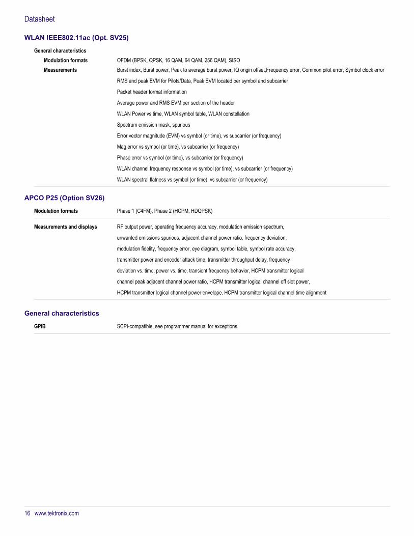
WLAN IEEE802.11ac (Opt. SV25)
General characteristicsModulation formats OFDM (BPSK, QPSK, 16 QAM, 64 QAM, 256 QAM), SISOMeasurements Burst index, Burst power, Peak to average burst power, IQ origin offset,Frequency error, Common pilot error, Symbol clock error
RMS and peak EVM for Pilots/Data, Peak EVM located per symbol and subcarrier
Packet header format information
Average power and RMS EVM per section of the header
WLAN Power vs time, WLAN symbol table, WLAN constellation
Spectrum emission mask, spurious
Error vector magnitude (EVM) vs symbol (or time), vs subcarrier (or frequency)
Mag error vs symbol (or time), vs subcarrier (or frequency)
Phase error vs symbol (or time), vs subcarrier (or frequency)
WLAN channel frequency response vs symbol (or time), vs subcarrier (or frequency)
WLAN spectral flatness vs symbol (or time), vs subcarrier (or frequency)
APCO P25 (Option SV26)
Modulation formats Phase 1 (C4FM), Phase 2 (HCPM, HDQPSK)
Measurements and displays RF output power, operating frequency accuracy, modulation emission spectrum,
unwanted emissions spurious, adjacent channel power ratio, frequency deviation,
modulation fidelity, frequency error, eye diagram, symbol table, symbol rate accuracy,
transmitter power and encoder attack time, transmitter throughput delay, frequency
deviation vs. time, power vs. time, transient frequency behavior, HCPM transmitter logical
channel peak adjacent channel power ratio, HCPM transmitter logical channel off slot power,
HCPM transmitter logical channel power envelope, HCPM transmitter logical channel time alignment
General characteristics
GPIB SCPI-compatible, see programmer manual for exceptions
Datasheet
16 www.tektronix.com

Ordering informationSignalVu™ Vector Signal Analysis software is compatible with all DPO/MSO5000 Series digital oscilloscopes with firmware version 6.1.1 and DPO7000, DPO/DSA/MSO70000Series digital oscilloscopes with firmware version V5.1.0 or higher. SignalVu Essentials (Opt. SVE) provides basic vector signal analysis and is required for all other analysisoptions.
OptionsOpt. SVE SignalVu Essentials - Vector Signal Analysis Software
Opt. SV23 WLAN 802.11a/b/g/j/p measurement application (requires opt. SVE, requires oscilloscope of bandwidth of 2.5 GHz or above)
Opt. SV24 WLAN 802.11n measurement application (requires opt SV23, requires oscilloscope of bandwidth of 2.5 GHz or above)
Opt. SV25 WLAN 802.11ac measurement application (requires opt SV24, requires oscilloscope of bandwidth of 6.0 GHz or above)
Opt. SV26 APCO P25 measurement application
Opt. SVP Advanced Signal Analysis, including pulse measurements (requires opt. SVE)
Opt. SVM General Purpose Digital Modulation Analysis (requires opt. SVE)
Opt. SVT Settling Time, Frequency, and Phase (requires opt. SVE)
Opt. SVO Flexible OFDM with support for 802.11a/j/g and 802.16-2044 (fixed WiMAX) modulation types. Not available on the MSO/DPO5000 Series (requires instruments with Windows 7 operating system)
Opt. SVA AM/FM/PM Modulation and Audio Measurements. Requires Opt. SVE (requires instruments with Windows 7 operating system)
SignalVu ordering and upgrade guide for new and existing instrumentsOption ordering nomenclature for all oscilloscopes. Option SVE is required for all other options listed. Option SVO is not available on MSO/DPO5000 models.
For information on analysis software that runs on your personal computer, please see the SignalVu-PC data sheet 37W-26988.
New and existing models Model Ordering on new instrument Upgrade existing instrumentMSO/DPO5000 Series Opt. SVE (Essentials) DPO-UP Opt. SVEEDPO7000 Series Opt. SVE (Essentials) DPO-UP Opt. SVEMDPO/DSA/MSO70000 Series ≤8 GHz Opt. SVE (Essentials) DPO-UP Opt. SVEHDPO/DSA/MSO70000 Series >8 GHz Opt. SVE (Essentials) DPO-UP Opt. SVEUOption SVE required for all other optionslisted
Opt. SVT (Settling time) DPO-UP Opt. SVTOpt. SVP (Pulse measurements) DPO-UP Opt. SVPOpt. SVM (GP modulation analysis) DPO-UP Opt. SVMOpt. SVO (OFDM) DPO-UP Opt. SVOOpt. SVA (AM/FM/PM Audio) DPO-UP Opt. SVAOpt. SV26 (APCO P25) DPO-UP Opt. SV26Opt. SV23 (IEEE802.11a/b/g/j/p) DPO-UP Opt. SV23
Option SV23 required for SV24 Opt. SV24 (IEEE802.11n) DPO-UP Opt .SV24Option SV24 required for SV25 Opt. SV25 (IEEE802.11ac) DPO-UP Opt. SV25
Legacy modelsDPO7000 Series, DPO/DSA/MSO70000 Series
Earlier DPO7000 and DPO/DSA/MSO70000 Series oscilloscopes may be retrofitted with SignalVu. These instruments use aMicrosoft Windows XP operating system, have oscilloscope firmware version 5.1 or above, and are compatible with SignalVuversion 2.3.0072. See upgrade nomenclature table above for ordering information. Option SVO (OFDM), Option SVA (AM/FM/PMAudio), and Options SV23, SV23, SV25, SV26 (WLAN and P25) are not available on instruments with Microsoft Windows XP.
SignalVu™ Vector Signal Analysis Software for Oscilloscopes
www.tektronix.com 17

Standard accessories— Reference Manual (PDF)— Printable Help (PDF)— Programmer Manual (on CD)
Tektronix is registered to ISO 9001 and ISO 14001 by SRI Quality System Registrar.
Product(s) complies with IEEE Standard 488.1-1987, RS-232-C, and with Tektronix Standard Codes and Formats.
Datasheet
ASEAN / Australasia (65) 6356 3900 Austria 00800 2255 4835* Balkans, Israel, South Africa and other ISE Countries +41 52 675 3777 Belgium 00800 2255 4835* Brazil +55 (11) 3759 7627 Canada 1 800 833 9200 Central East Europe and the Baltics +41 52 675 3777 Central Europe & Greece +41 52 675 3777 Denmark +45 80 88 1401 Finland +41 52 675 3777 France 00800 2255 4835* Germany 00800 2255 4835*Hong Kong 400 820 5835 India 000 800 650 1835 Italy 00800 2255 4835*Japan 81 (3) 6714 3010 Luxembourg +41 52 675 3777 Mexico, Central/South America & Caribbean 52 (55) 56 04 50 90 Middle East, Asia, and North Africa +41 52 675 3777 The Netherlands 00800 2255 4835* Norway 800 16098 People's Republic of China 400 820 5835 Poland +41 52 675 3777 Portugal 80 08 12370 Republic of Korea 001 800 8255 2835 Russia & CIS +7 (495) 6647564 South Africa +41 52 675 3777 Spain 00800 2255 4835* Sweden 00800 2255 4835* Switzerland 00800 2255 4835*Taiwan 886 (2) 2722 9622 United Kingdom & Ireland 00800 2255 4835* USA 1 800 833 9200
* European toll-free number. If not accessible, call: +41 52 675 3777 Updated 10 April 2013
For Further Information. Tektronix maintains a comprehensive, constantly expanding collection of application notes, technical briefs and other resources to help engineers working on the cutting edge of technology. Please visit www.tektronix.com.
Copyright © Tektronix, Inc. All rights reserved. Tektronix products are covered by U.S. and foreign patents, issued and pending. Information in this publication supersedes that in all previously published material. Specification andprice change privileges reserved. TEKTRONIX and TEK are registered trademarks of Tektronix, Inc. All other trade names referenced are the service marks, trademarks, or registered trademarks of their respective companies.
06 Aug 2014 37W-22314-13
www.tektronix.com