Bedienungsanleitung MPB 4000 - berghaus-verkehrstechnik.de · I. Introduction The MPB 4000 is the...
96
Operation Manual Building Site Signalling Equipment MPB 4000
Transcript of Bedienungsanleitung MPB 4000 - berghaus-verkehrstechnik.de · I. Introduction The MPB 4000 is the...

Operation Manual
Building Site Signalling EquipmentMPB 4000


General explanation of building site signalling equipment
Signal safety
The use of transportable building site signalling equipment, among other things, isdescribed in the regulations of the VDE and the RiLSA.The above regulations determine that on building sites with one-way trafficregulations and a speed limit of 30 km/h, for example,
as long as the responsible authorities donot change their conditions or increase their requirements.
All other building site signalling equipment for controlling traffic at junctions orcrossings or, for example, pedestrian crossings
An acknowledgement that can be given via radio or cable is required for this signalprotection. With radio-controlled signalling equipment, high-quality radiocomponents which have a Reg TP (Federal Office for Telecommunication Licenses)approval number are used. The radio signals have a range of up to 2000 metres.
signal protection in accordancewith RiLSA and VDE 0832 is unnecessary
must have signal protection inaccordance with RiLSA and VDE 0832.
The company Peter Berghaus GmbH manufactures and delivers building sitesignalling equipment
or signal protection.with without
Transport information- please observe!
Our building site signalling equipment mustbe . All signal
transmission chambers and the controlhousing must always be closed properly and
the control chamber must be locked to preventdamage from water!
If you do not observe this advice, you willautomatically lose your guarantee!
standing when being transported

TABLE OF CONTENTS
I. Presentation of the MPB 4000 and Manual Device Models
II. Programming / Re-programming
III. Special Options with Quartz Operation
Pages 1 to 2
Pages 3 to 61
1. One-Way Alternating-Direction TrafficPages 3 to 6
2. One-Way Alternating-Direction Traffic with Special Options(see Chapters III + IV)Pages 7 to 12
3. One-Way Alternating-Direction Traffic that is Traffic-Flow-DependentPages 13 to 15
4. One-Way Alternating-Direction Traffic that is Traffic-Flow-Dependent, with Special Options (see Chapters III + IV)Pages 16 to 21
5. Intersection TrafficPages 22 to 26
6. Intersection Traffic with Special Options(see Chapters III + IV)Pages 27 to 33
7. Intersection Traffic that is Traffic-Flow DependentPages 34 to 38
8. Intersection Traffic that is Traffic-Flow Dependentwith Special Options (see Chapters III + IV)Pages 39 to 45
9. Re-programming, or changes in the timings of a working traffic lightPages 46 to 47
(Night-time Mode)Page 48
IV. Special Options with Radio and Cable Operation
V. Auxiliary Functions
VI. Control Device / Error Messagesfor Control Device
VII. Manual Device / Error Messagesfor Manual Device
VIII. Accessories
IX. Technical Data
X. Directions for Radar Detector
XI. Spare Parts List
XII. Forms
(Night-time Mode, Day Programmes, Intervalmatrix, Forced Circulation and Data Transmissionvia PC)Pages 49 to 51
(ManualOperation, Setting the Time of Day,Selecting Programmes, VersionDisplay and ErrorAcknowledgement)Pages 52 to 61
Pages 62 to 65
Pages 66 to 69
Page 70
Page 71
Pages 72 to 80
Pages 81 to 82

I. Introduction
The MPB 4000 is the universal signal equipment for all trafficsituations subject to traffic light control, including installations for thefollowing traffic patterns: one-way alternating-direction; junction-merging and pedestrian installations; also for intersection signalinstallations with 12 groups and a maximum of 24 signal heads withcontrol units that are 100% identical in construction.
The installation can be supplied as or.
In cable as well as in radio mode, the equipment possesses all
All data such as signal time plans and malfunctions with date can beprinted out on a printer.
The following operating modes are possible:
1. Fixed time programme as well as fixed time programme with up to4 daytime programmes
2. Traffic-flow-dependent mode as well as traffic-flow-dependentmode with up to 4 daytime programmes
3. Traffic-flow-dependent mode with green on demand with up to 4daytime programmes
4. Flashing and darkness programme
Up to 4 start times with different blocks of days can be entered for allprogrammes.
Quartz, Cable Quartz, Cable-Radio Equipment
monitor features specified by RiLSA:
- Red Light Monitoring- Green-Green Prevention- Green Status- Interval Monitoring (required acc. to RiLSA,
Appendix G.3)- Watch Dog (computer monitoring)
�

MANUAL DEVICE MODELS
Switching the manual device off and on
Before you can set the manual device into operation, the batteries (4*Mignon) that are supplied with it must first be installed.To do this, openthe battery chamber on the rear side of the device and insert the batteries(be sure the polarity is correct!).To switch the device on, briefly pressthe "ON" key.The manual device will then display the manual device model. You can
the manual device by holding the #2 key pressed down for ca.5 seconds.
The display shows the following, depending upon manual devicemodel:
Chapter II Number 1 + 2
Chapter II Number 3 + 4
Chapter II Number 5 + 6
Chapter II Number 7 + 8
You have different programming possibilities available to you,depending upon manual device model.These are explained in detail inthe Chapters listed next to the manual device displays.
switch off
**M P B 4000**One Way Traffic
* M P B 4000 VA*One Way Traffic
**M P B 4000**Cross-roads
* M P B 4000 VA*Cross-roads
�

1. Input for One-Way Alternating-DirectionTraffic
Before programming the signal equipment, you should make sure thatthe time of day and date are set correctly in the manual device. You candetermine this by switching on the manual device. After approximately10 seconds, the current time of day and date are presented automaticallyin the display. If the information shown is not correct, then reset thenumbers as described in the "Auxiliary Functions" Chapter on page 52of this manual. Switch further using key #4 until the manual device tellsyou to program the traffic light. In doing so, the manual device requestsa variety of entries. You can alter the date by using the keys #1 and #3.The number that is currently valid will be flashing. If you hold the keypressed down for a longer time, then the numbers change more quickly.
The display shows:
Select with the keys #1 and #3 the desired operating mode, for example"Quartz" for quartz operation.
With key #4 you then move further to the point for entering the
ere you can alter the length of the roadworks site using the keys #1 and
without traffic-flow dependency and without specialoptions
You can programme one-way alternating-directiontraffic with this manual device.
H
Please select:Quartz Radio Cable
Site length:>-< 50 m >+<
**M P B 4000**One Way Traffic
�

#3.Once the value is set, proceed further with key #4.
The current speed will be flashing. Set the required speed for within theroadworks site.Then press key #4 again. The following will appear:
These two times have been calculated by the manual device.For safety reasons, the displayed periods for traffic-clearing must beconsidered irreducible minimums. It is however possible to increase thetimes using key #3--to different extents, if desired: Thus, at a roadworks site on a mountain, for example, the ascending traffic can beallowed a longer traffic-clearing period. Traffic-clearing period #1 endswhen traffic light #2 has finished its green signal.Press key #4 once again and follow the display in the manualdevice:
The displayed value in the line in which the arrow is blinking can bealtered using keys #1 and #3. With key #4, one moves one line down,and can then alter the time setting there.At this point, all the entries in the manual device are completed.
Press key #4 once again. The display shows:
After the formulation of the signal plan, the display switches to thefollowing message:
Clr.time 1 => 10sClr.time 2 = 10s
Select: (km/h)10 40 50 7030
Grn.time 1 => 5sGrn.time 2 = 5s
Makingsignalplan
�
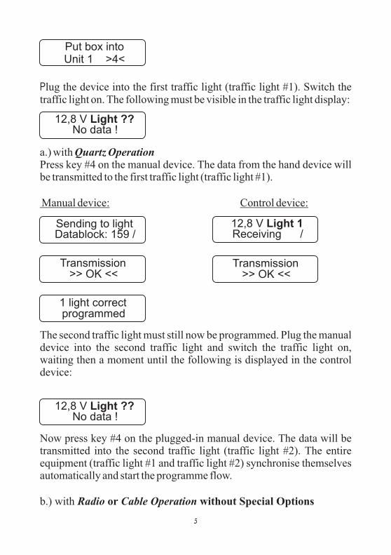
Plug the device into the first traffic light (traffic light #1). Switch thetraffic light on. The following must be visible in the traffic light display:
a.) withPress key #4 on the manual device. The data from the hand device willbe transmitted to the first traffic light (traffic light #1).
The second traffic light must still now be programmed. Plug the manualdevice into the second traffic light and switch the traffic light on,waiting then a moment until the following is displayed in the controldevice:
Now press key #4 on the plugged-in manual device. The data will betransmitted into the second traffic light (traffic light #2). The entireequipment (traffic light #1 and traffic light #2) synchronise themselvesautomatically and start the programme flow.
b.) with
Quartz Operation
Radio Cable Operation
Manual device: Control device:
or without Special Options
Put box intoUnit 1 >4<
12,8 V Light ??No data !
12,8 V Light ??No data !
Sending to lightDatablock: 159 /
12,8 V Light 1Receiving /
Transmission>> OK <<
Transmission>> OK <<
1 light correctprogrammed
�

The selection proceeds as described in Item 1.2. You select however,
epending upon the connection mode, not quartz but either radio orcable instead. For this you need programme only one traffic light withthe manual device. Once you have ,switch on .Once it is programmed, this will be known as traffic light #1.The following must be displayed in the control device:
The cable linkage is not required with a radio installation. Programmethe first traffic light (traffic light #1) with the manual device, for whichyou plug the manual device into the traffic light and press key #4 afterthe display calls for it. The two displays then show the following:
After switching on traffic light #2, the programme is transmitted byradio or cable to the other traffic light (traffic light #2) and theinstallation starts up completely automatically.
(Flashing, Lights Off, All-Red and Programme Selection)The procedural methods with manual options can be found in Chapter V"Auxiliary Functions", on page 52 of this manual.
d
linked the equipment with cables
Manual device: Control device:
one traffic light
Manual Options:
Warning: In the event of a data loss at traffic light #1 or #2 (throughactivation of the on/off switch), the entire installation must be re-programmed in the case of a .radio signal installation
12,8 V Light 1Light 2 missing !
12,8 V Light ??No data !
�
Sending to lightDatablock: 159 /
12,8 V Light 1Receiving /
Transmission>> OK <<
Transmission>> OK <<
1 light correctprogrammed

2. Input for One-Way Alternating-Direction TrafficRadio or cable operation without traffic-flowdependency, but with special options such as Night-time Mode, Day Programmes, Interval matrix,Forced Circulation and Data Transmission via PC
With this manual device you can programme one-way alternating-direction traffic without traffic-flow dependency, although withspecial options. Directions for setting the special options can befound starting on page 47 of this manual.
Before programming the signal equipment, you should make sure thatthe time of day and date are set correctly in the manual device. You candetermine this by switching on the manual device. After approximately10 seconds, the current time of day and date are presented automaticallyin the display. If the information shown is not correct, then reset thenumbers as described in the "Auxiliary Functions" Chapter on page 52of this manual.Switch further using key #4 until the manual device tells you toprogramme the traffic light. In doing so, the manual device requests avariety of entries. You can alter the date by using the keys #1 and #3.The number that is currently valid will be flashing.If you hold the key pressed down for a longer time, then the numberschange more quickly.
The display shows:
Select with the keys #1 and #3 the desired operating mode, for example"Cable" or "Radio" (the only special option available with quartzoperation is Night-time Mode).With key #4 you then move further to the point of entering the
**M P B 4000**Einbahnwechsel
Please select:Quartz Radio Cable
�

Here you can alter the length of the roadworks site using the keys #1 and#3.Once the value is set, proceed further with key #4.
The current speed will be flashing. Set the required speed for within theroadworks site.Then press key #4. The following will appear:
These two times have been calculated by the manual device. For safetyreasons, the displayed periods for traffic-clearing must be consideredirreducible minimums. It is however possible to increase the timesusing key #3--to different extents, if desired: Thus, at a road works siteon a mountain, for example, the ascending traffic can be allowed alonger traffic-clearing period. Traffic-clearing period #1
.Press key #4 once again and follow the display in the manual device. Ifyou have selected Daytime Programme as a special option, then thefollowing display appears. The method used to activate the specialoptions is described in the annex under "Special Options".
Here you are called upon to enter the 1st Daytime Programme:
The displayed value in the line in which the arrow is blinking can bealtered using keys #1 and #3. With key #4, one moves one line down,and can then alter the time setting there.
ends whentraffic light #2 has finished its "Green"
Input >4<Dayprogram 1
Site length:>-< 50 m >+<
Select: (km/h)10 40 50 7030
Clr.time 1 => 10sClr.time 2 = 10s
Grn.time 1 => 5sGrn.time 2 = 5s
�

When you are carrying out a re-programming, you have the opportunityof deleting old switch points that may be left over from a previousprogramming. For this, select "Yes", and confirm your choice with key#4.
Once you have completed these entries, the manual device will ask youfor 4 switch points for the entered Daytime Programme #1. This meansthat once you have entered a Daytime Programme, you can have it startitself as many as four times a day, at the different times that you select:
00:00 means in this connection no input. For midnight, you must enter24:00After entering the starting time, you will be called upon to specify thedays on which the programme is to be used.
If you have selected two or more Daytime Programmes, then you willnow be called upon to enter these as described above (Enter DaytimeProgramme #2).After this entry, you have the opportunity of determining the Night-timeMode, if you have activated it as described in the annex under "SpecialOptions".
If you select "Yes" here, then you will be called upon to programme theNight-time Mode:
Here you are asked to select 4 switch points for the Night-time Mode.This means you can have the Night-time Mode start itself as many asfour times a day, at the different times that you select:
Switchp. clear ?yes no
Switchp. 1 Pro 1Start:>06:00 Uhr
Select Daysall Mo-Fr Sa-So
Nightmode:yes no
Input >4<Nightprog. darkl

00:00 means in this connection no input. For midnight, you musttherefore enter 24:00After entering the starting time, you will be called upon to specifythe days on which the programme is to be used.
Afterwards, you have the opportunity to set the Night-time Mode forFlashing:
Here you are asked to select 4 switch points for the Night-time Mode.This means you can have the Night-time Mode start itself as many asfour times a day, at the different times that you select:
00:00 means in this connection no input. For midnight, you musttherefore enter 24:00After entering the starting time, you will be called upon to specify thedays on which the programme is to be used.
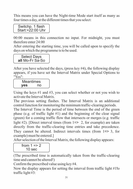
After you have selected the days, (press key #4), the following displayappears, if you have set the Interval Matrix under Special Options to"Yes":
Using the keys #1 and #3, you can select whether or not you wish toactivate the Interval Matrix.The previous setting flashes. The Interval Matrix is an additionalcontrol function for monitoring the minimum traffic-clearing periods.
Switchp. 1 offStart:>23:00 Uhr
Switchp. 1 flashStart:>22:00 Uhr
Meantimesyes no
Select Daysall Mo-Fr Sa-So
Input >4<Nightprog. flash
Select Daysall Mo-Fr Sa-So
�

The Interval Time is the period of time between the end of the greenphase (e.g. of traffic light #1) and the beginning of the clear signal(green) for a coming traffic flow that intersects or merges (in this casetraffic light #2, as one-way alternating-direction traffic operation wasselected). Traffic-clearing time computation proceeds automaticallyfor one-way alternating-direction traffic.After selection of the Interval Matrix, the following display appears:
For one-way alternating-direction traffic, the intervals are adoptedautomatically from the traffic-clearing times, and can no longer bealtered. This serves for adoption of the minimum traffic-clearing times.Confirm this with key #>4<. Now the display appears for setting theinterval from traffic light #2 to traffic light #1 (this, too, will beautomatically adopted):
At this point, all the entries in the manual device are completed. Presskey #4 once again. The display shows:
After the formulation of the signal plan, the display switches to thefollowing message:
Switch on a traffic light (which then automatically becomes traffic light#1). The following must be visible in the traffic light display:
Plug the device into the first traffic light (traffic light #1). Press key #4on the manual device. The data from the hand device will be transmittedto the first traffic light (traffic light #1).
from 1 => 210 sec
from 2 => 110 sec
Makingsignalplan
Put box intoUnit 1 >4<
12,8 V Light ??No data !
��

Manual device Control device::
After switching on traffic light #2, the programme is transmitted byradio or cable to the other traffic light (traffic light #2) and theinstallation starts up completely automatically.
(Flashing, Lights Off, All-Red and Programme Selection)The procedural methods with manual options can be found in Chapter V"Auxiliary Functions", on page 52 of this manual.
Warning: In the event of a data loss at traffic light #1 or #2 (throughactivation of the on/off switch), the entire installation must be re-programmed in the case of a .radio signal installation
Manual Options:
��
12,8 V Light 1Light 2 missing !
Sending to lightDatablock: 159 /
12,8 V Light 1Receiving /
Transmission>> OK <<
Transmission>> OK <<
1 light correctprogrammed

3. Input for One-Way Alternating-Direction TrafficWith traffic-flow dependency but without specialoptions
With this manual device you can programme one-way alternating-direction traffic with traffic-flow dependency, although withoutspecial options.
no
Before programming the signal equipment, you should make sure thatthe time of day and date are set correctly in the manual device. You candetermine this by switching on the manual device.After approximately 10 seconds, the current time of day and date arepresented automatically in the display. If the information shown is notcorrect, then reset the numbers as described in the "AuxiliaryFunctions" Chapter on page 52 of this manual. Switch further using key#4 until the manual device tells you to programme the traffic light. Indoing so, the manual device requests a variety of entries. You can alterthe date by using the keys #1 and #3. The number that is currently validwill be flashing.If you hold the key pressed down for a longer time, then the numberschange more quickly.
The display shows:
Select with the keys #1 and #3 the desired operating mode, for example"Cable" or "Radio". If "Quartz" is selected, then traffic-flowdependency is possible.With key #4 you then move further to the point of entering the traffic-flow dependency:
* M P B 4000 VA*Einbahnwechsel
Traffic related:yes no
Please select:Quartz Radio Cable
��

S
A
et the traffic-flow dependency to "Yes" ("Yes" flashes) and confirm theselection with key #4. The manual device display shows the following:
Here you can alter the length of the roadworks site using the keys #1 and#3. Once the value is set, proceed further with key #4.
The current speed will be flashing. Set the required speed for within theroadworks site. Then press key #4 again. The following will appear:
These two times have been calculated by the manual device. For safetyreasons, the displayed periods for traffic-clearing must be consideredirreducible minimums. It is however possible to increase the timesusing key #3--to different extents, if desired: Thus, at a road works siteon a mountain, for example, the ascending traffic can be allowed alonger traffic-clearing period. Traffic-clearing period #1 ends whentraffic light #2 has finished its green signal.Press key #4 once again and follow the display in the manual device:
Now one can set a minimum and a maximum green time for signalgroup #1. Continue with key #4.
Now the same entries are made as above, this time for signal group #2.At this point, all the entries in the manual device are completed. Presskey #4 once again. The display shows:
fter the formulation of the signal plan, the display switches to the
Grn2 min => 10sGrn2 max = 25s
Grn1 min => 10sGrn1 max = 35s
Site length:>-< 50 m >+<
Select: (km/h)10 40 50 7030
Clr.time 1 => 10sClr.time 2 = 10s
Makingsignalplan
��

following message:
Switch on a traffic light (which then automatically becomes traffic light#1). The following must be visible in the traffic light display:
Plug the device into the first traffic light (traffic light #1). Press key #4on the manual device. The data from the hand device will be transmittedto the first traffic light (traffic light #1).
After switching on traffic light #2, the programme is transmitted byradio or cable to the other traffic light (traffic light #2) and theinstallation starts up completely automatically.
(Flashing, Lights Off, All-Red and Programme Selection)The procedural methods with manual options can be found in Chapter V"Auxiliary Functions", on page 52 of this manual.
Manual device: Control device:
Warning: In the event of a data loss at traffic light #1 or #2 (throughactivation of the on/off switch), the entire installation must be re-programmed in the case of a .radio signal installation
Manual Options:
Put box intoUnit 1 >4<
12,8 V Light ??No data !
��
12,8 V Light 1Light 2 missing !
Sending to lightDatablock: 159 /
12,8 V Light 1Receiving /
Transmission>> OK <<
Transmission>> OK <<
1 light correctprogrammed

4. Input for One-Way Alternating-Direction TrafficRadio or cable operation with traffic-flowdependency and with special options such as Night-time Mode, Day Programme, Interval matrix,Forced Circulation and Data Transmission via PC
With this manual device you can programme one-way alternating-direction traffic with traffic-flow dependency and with specialoptions. Directions for setting the special options can be foundstarting on page 47 of this manual.
Before programming the signal equipment, you should make sure thatthe time of day and date are set correctly in the manual device. You candetermine this by switching on the manual device. After approximately10 seconds, the current time of day and date are presented automaticallyin the display. If the information shown is not correct, then reset thenumbers as described in the "Auxiliary Functions" Chapter on page 52of this manual.Switch further using key #4 until the manual device tells you toprogramme the traffic light. In doing so, the manual device requests avariety of entries. You can alter the date by using the keys #1 and #3.The number that is currently valid will be flashing.If you hold the key pressed down for a longer time, then the numberschange more quickly.
The display shows:
Select with the keys #1 and #3 the desired operating mode, for example"Cable" or "Radio".If "Quartz Operation“ is selected, neither traffic flow dependency norspecial options such as Daytime Programme and Time Interval are
**M P B 4000**Einbahnwechsel
Please select:Quartz Radio Cable
��

possible. ith key #4 you then move further to the point of entering thetraffic flow dependency:
Set the traffic-flow dependency to "Yes" ("Yes" flashes) and confirmthe selection with key #4. Pressing key #4 brings you then further to thepoint of entering
Here you can alter the length of the roadworks site using the keys #1 and#3.Once the value is set, proceed further with key #4.
The current speed will be flashing. Set the required speed for within theroadworks site.Then press key #4 again. The following will appear:
These two times have been calculated by the manual device.For safety reasons, the displayed periods for traffic-clearing must beconsidered irreducible minimums. It is however possible to increase thetimes using key #3--to different extents, if desired: Thus, at a roadworks site on a mountain, for example, the ascending traffic can beallowed a longer traffic-clearing period. Traffic-clearing period #1 endswhen traffic light #2 has finished its "green".
Press key #4 once again and follow the display in the manual device. Ifyou have selected Daytime Programme as a special option, then thefollowing display appears. The method used to activate the specialoptions is described in the annex under "Special Options".
ere you are called upon to enter the 1st Daytime Programme:
W
H
Traffic related:yes no
Site length:>-< 50 m >+<
Select: (km/h)10 40 50 7030
Clr.time 1 => 10sClr.time 2 = 10s
Input >4<Dayprogram 1
��

Now one can set minimum and maximum green times for signal group#1. Continue with key #4.
Now the same entries are made as above, this time for signal group #2.The displayed value in the line in which the arrow is blinking can bealtered using keys #1 and #3. With key #4, one moves one line down,and can then alter the time setting there.
When you are carrying out a re-programming, you have the opportunityof deleting old switch points that may be left over from a previousprogramming. For this, select "Yes", and confirm your choice with key#4.Once you have completed these entries, the manual device will ask youfor 4 switch points for the entered Daytime Programme #1. This meansthat once you have entered a Daytime Programme, you can have it startitself as many as four times a day, at the different times that you select:
00:00 means in this connection no input. For midnight, you must enter24:00After entering the starting time, you will be called upon to specify thedays on which the programme is to be used.
If you have selected more than one Daytime Programme, then you willnow be called upon to enter these as described above (Enter DaytimeProgramme #2).After this entry, you have the opportunity of determining the NighttimeMode,if you have activated it as described in the annex under "SpecialOptions”.
Grn1 min => 10sGrn1 max = 30s
Grn2 min => 10sGrn2 max = 25s
Switchp. clear ?yes no
Switchp. 1 Pro 1Start:>06:00 Uhr
Select Daysall Mo-Fr Sa-So
��

If you select "Yes" here, then you will be called upon to programme theNight-time Mode:
Here you are asked to select 4 switch points for the Night-time Mode.This means you can have the Night-time Mode start itself as many asfour times a day, at the different times that you select:
00:00 means in this connection no input. For midnight, you musttherefore enter 24:00After entering the starting time, you will be called upon to specify thedays on which the programme is to be used.
Afterwards, you have the opportunity to set the Night-time Mode forFlashing:
Here you are asked to select 4 switch points for the Night-time Mode.This means you can have the Night-time Mode start itself as many asfour times a day, at the different times that you select:
00:00 means in this connection no input. For midnight, you musttherefore enter 24:00
After entering the starting time, you will be called upon to specify thedays on which the programme is to be used.
Switchp. 1 offStart:>23:00 Uhr
Nightmode:yes no
Input >4<Nightprog. darkl
Select Daysall Mo-Fr Sa-So
Input >4<Nightprog. flash
Switchp. 1 flashStart:>22:00 Uhr
�

After you have selected the days, (press key #4), the following displayappears, if you have set the Interval Matrix under Special Options to"Yes":
Using the keys #1 and #3, you can select whether or not you wish toactivate the Interval Matrix. The previous setting flashes. The IntervalMatrix is an additional control function for monitoring the minimumtraffic-clearing periods.The Interval Time is the period of time between the end of the greenphase (e.g. of traffic light #1) and the beginning of the clear signal(green) for a coming traffic flow that intersects or merges (in this casetraffic light #2, as one-way alternating-direction traffic operation wasselected). Traffic-clearing time computation proceeds automaticallyfor one-way alternating-direction traffic.After selection of the Interval Matrix, the following display appears:
For one-way alternating-direction traffic, the intervals are adoptedautomatically from the traffic-clearing times, and can no longer bealtered. This serves for adoption of the minimum traffic-clearing times.Confirm this with key #>4<. Now the display appears for setting theinterval from traffic light #2 to traffic light #1 (this, too, will beautomatically adopted):
At this point, all the entries in the manual device are completed.Press key #4 once again. The display shows:
After the formulation of the signal plan, the display switches to thefollowing message:
Select Daysall Mo-Fr Sa-So
Meantimesyes no
from 1 => 210 sec
from 2 => 110 sec
Makingsignalplan
�

Switch on a traffic light (which then automatically becomes traffic light#1). The following must be visible in the traffic light display:
Plug the device into the first traffic light (traffic light #1). Press key #4on the manual device.
The data from the hand device will be transmitted to the first traffic light(traffic light #1).
After switching on traffic light #2, the programme is transmitted byradio or cable to the other traffic light (traffic light #2) and theinstallation starts up completely automatically.
(Flashing, Lights Off, All-Red and Programme Selection)The procedural methods with manual options can be found in Chapter V"Auxiliary Functions", on page 52 of this manual.
Manual device: Control device:
Warning: In the event of a data loss at traffic light #1 or #2 (throughactivation of the on/off switch), the entire installation must be re-programmed in the case of a .radio signal installation
Manual Options:
Put box intoUnit 1 >4<
12,8 V Light ??No data !
��
12,8 V Light 1Light 2 missing !
Sending to lightDatablock: 159 /
12,8 V Light 1Receiving /
Transmission>> OK <<
Transmission>> OK <<
1 light correctprogrammed

5. Input for Junction-Merging andIntersection TrafficWithout traffic-flow dependency and without specialoptions
With this manual device you can programme junction-mergingand/or intersection traffic for up to 4 groups and 24 signal headswith cable, and 4 signal heads with radio operation, without traffic-flow dependency and without special options.
Before programming the signal equipment, you should make sure thatthe time of day and date are set correctly in the manual device. You candetermine this by switching on the manual device.After approximately 10 seconds, the current time of day and date arepresented automatically in the display. If the information shown is notcorrect, then reset the numbers as described in the "AuxiliaryFunctions" Chapter on page 52 of this manual. Switch further using key#4 until the manual device tells you to programme the traffic light. Indoing so, the manual device requests a variety of entries. You can alterthe date by using the keys #1 and #3. The number that is currently validwill be flashing. If you hold the key pressed down for a longer time, thenthe numbers change more quickly.The display shows:
Select with the keys #1 and #3 the desired operating mode, for example"Cable" for cable operation.With key #4 you then move further to the point of entering the totalnumber of groups:
The current total will be flashing. You can now raise or lower the total,
**M P B 4000**Cross-roads
Number groups:One way 3 4
Please select:Quartz Radio Cable
��
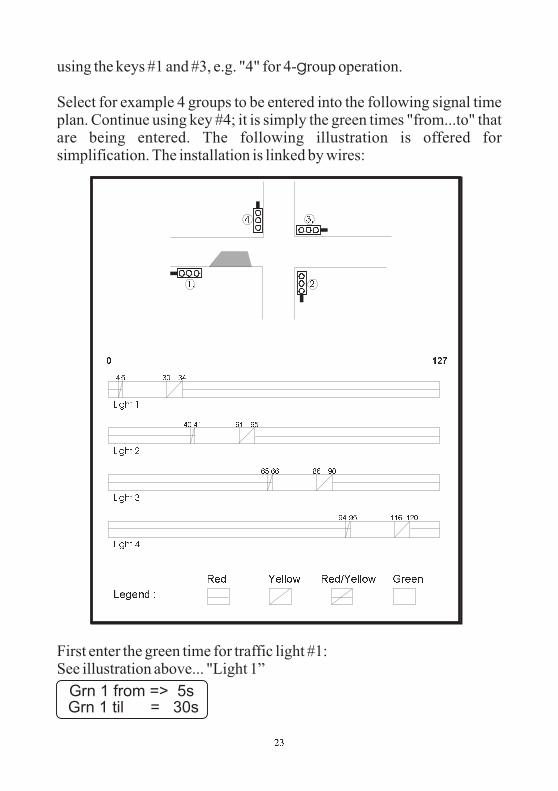
using the keys #1 and #3, e.g. "4" for 4- roup operation.
Select for example 4 groups to be entered into the following signal timeplan. Continue using key #4; it is simply the green times "from...to" thatare being entered. The following illustration is offered forsimplification. The installation is linked by wires:
First enter the green time for traffic light #1:See illustration above... "Light 1”
g
�� ��
����
��� �
�� �� ��
�� �� ��
�� �� ��
�� ��� ����
��
��
��� �
��� �
��� �
������ �
��� ��� � ����������
� ���
Grn 1 from => 5sGrn 1 til = 30s
��

H
t
ere, where the arrow is flashing, one can raise or lower the number ofseconds. In the above illustration, traffic light #1 would show greenfrom the fifth to the thirtieth second. If one had selected the operatingmode "cable" or "radio" at the start, then one can still enter the numberof signal heads after every "from...to" time entry. A distinction is madewhen doing so between roadway and pedestrian signal heads.A pedestrian signal head stands at double red. You can simply insert apedestrian symbol behind the diffusion plate. For entering the totalnumber of signal heads of the different signal groups, the followingdisplay appears in the manual device:
You can enter the number of the roadway signal heads in the first line:key #3 for more signal heads, key #1 for fewer. Pressing key #4 bringsyou into the second line, where one enters the total of pedestrian signalheads that functions parallel to the roadway signal heads of group #1.
If you select "Yes" during malfunction flashing, then the entire signalgroup shows "Yellow flashing" in the case of a malfunction (pedestriansignal heads are dark). Should you have altered the pre-setting to "No",then the entire signal group shows "Dark".The entries for the groups #2, #3 and #4 are carried out in precisely thesame way.Continue with key #4.
The manual device presents automatically a circulation time, but thismust be altered to the prescribed value according to the signal time plan.
Then press key #4 again. The display shows:
After creation of the signal plan, the display changes to he followingmessage:
Shead Gr1> 1Shead Gr1 0
F. blinking 1 :yes no
Circ. time=> 127s
Makingsignalplan
��

Plug the device into traffic light #1. Switch the traffic light on. Thetraffic light display shows the following:
Press key #4. The data from the hand device will be transmitted to thetraffic light. The display in the manual device shows the following:
With radio or cable operation, you only need programme traffic signal#1 with the manual device. After you have wired the installation, or inthe case of a radio installation, simply switch the other traffic lights on,
.
Not until the last signal head is switched onand the data has been transmitted via radio or cable does the installationstart up automatically through the switching-on programme.
Manual device: Control device:
one after the otherThe switching-on sequence of the signal heads determines therelationship to the signal groups with the corresponding number ofsignal heads per group.
Warning: In the event of a data loss at traffic light #1 or #2 (throughactivation of the on/off switch), the entire installation must be re-programmed in the case of a .radio signal installation
Put box intoUnit 1 >4<
12,8 V Light ??No data !
��
12,8 V Light 1Light 2 missing !
Sending to lightDatablock: 159 /
12,8 V Light 1Receiving /
Transmission>> OK <<
Transmission>> OK <<
1 light correctprogrammed

Manual Options:(Flashing, Lights Off, All-Red and Programme Selection)The procedural methods with manual options can be found in Chapter V"Auxiliary Functions", on page 52 of this manual.
��

6. Input for Junction-Merging andIntersection Trafficwithout traffic-flow dependency, but with specialoptions such as Night-time Mode, Day Programmes,Interval matrix, Forced Circulation and DataTransmission via PC
With this manual device you can programme junction-mergingand/or intersection traffic for up to 4 groups and 24 signal headswith cable, and 4 signal heads with radio operation, without traffic-flow dependency but with special options. Directions for setting thespecial options can be found starting on page 49 of this manual.
Before programming the signal equipment, you should make sure thatthe time of day and date are set correctly in the manual device. You candetermine this by switching on the manual device. After approximately10 seconds, the current time of day and date are presented automaticallyin the display. If the information shown is not correct, then reset thenumbers as described in the "Auxiliary Functions" Chapter on page 50of this manual.Switch further using key #4 until the manual device tells you toprogramme the traffic light. In doing so, the manual device requests avariety of entries. You can alter the date by using the keys #1 and #3.The number that is currently valid will be flashing.If you hold the key pressed down for a longer time, then the numberschange more quickly.
The display shows:
Select with the keys #1 and #3 the desired operating mode, for example"Cable" or "Radio".
**M P B 4000**Cross-roads
Please select:Quartz Radio Cable
��

With key #4 you then move further to the point of entering the numberof groups:
he current number of groups will be flashing. You can now raise orlower the total, using the keys #1 and #3, e.g. "4" for 4-group operation.Press key #4 once again and follow the display on the manual device. Ifyou have selected as a special option "Daytime Programme", thefollowing display will appear. The method used to activate the specialoptions is described in the annex under "Special Options".
Now you are called upon to enter the 1st daytime programme:
First enter the green time for traffic light #1:(See for this the signal time plan example without daytime programmeon page 23)Here, where the arrow is flashing, one can raise or lower the number ofseconds. Traffic light #1 would show green in the case presented abovefrom the second to the seventh second.
If one had selected the operating mode "cable" or "radio" at the start,then one can still enter the number of signal heads after every"from...to" time entry. A distinction is made when doing so betweenroadway and pedestrian signal heads.A pedestrian signal head stands at double red. You can simply insert apedestrian symbol behind the diffusion plate. For entering the totalnumber of signal heads of the different signal groups, the followingdisplay appears in the manual device:
You can enter the number of the roadway signal heads in the first line:key #3 for more signal heads, key #1 for fewer. Pressing key #4 brings
T
Number groups:One way 3 4
Input >4<Dayprogram 1
Grn 1 from => 5sGrn 1 til = 30s
Shead Gr1> 1Shead Gr1 0
��

you into the second line.
ne enters there the total of pedestrian signal heads that functionsparallel to the roadway signal heads of group #1.
If you select "Yes" during malfunction flashing, then the entire signalgroup shows "Yellow flashing" in the case of a malfunction (pedestriansignal heads are dark). Should you have altered the pre-setting to "No",then the entire signal group shows "Dark".The entries for the groups #2, #3 and #4 are carried out in precisely thesame way.Continue with key #4.
The manual device presents automatically a circulation time, but thismust be altered to the prescribed value according to the signal time plan.
Press key #4 to reach the next menu.
When you are carrying out a -programming, you have the opportunityof deleting old switch points that may be left over from a previousprogramming. For this, select "Yes", and confirm your choice with key#4.
Here the manual device will ask you for 1-4 switch points for theentered Daytime Programme #1.This means that once you have entered a Daytime Programme, you canhave it start itself as many as four times a day, at the different times thatyou select:
00:00 means in this connection no input. For midnight, you mustenter 24:00
O
re
F. blinking 1 :yes no
Circ. time=> 127s
Switchp. clear ?yes no
Switchp. 1 Pro 1Start:>06:00 Uhr
�

A
H
fter entering the starting time, you will be called upon to specify thedays on which the programme is to be used.
If you have selected more than one Daytime Programme, then you willnow be called upon to enter these as described above (Enter DaytimeProgramme #2).
After this entry, you have the opportunity of determining the Night-timeMode, if you have activated it as described in the annex under "SpecialOptions".
If you select "Yes" here, then you will be called upon to programme theNight-time Mode:
Here you are asked to select 4 switch points for the Night-time Mode.This means you can have the Night-time Mode start itself as many asfour times a day, at the different times that you select:
00:00 means in this connection no input. For midnight, you musttherefore enter 24:00After entering the starting time, you will be called upon to specify thedays on which the programme is to be used.
Afterwards, you have the opportunity to set the Night-time Mode forFlashing:
ere you are asked to select 4 switch points for the Night-time Mode.
Select Daysall Mo-Fr Sa-So
Nightmode:yes no
Input >4<Nightprog. darkl
Switchp. 1 offStart:>23:00 Uhr
Select Daysall Mo-Fr Sa-So
Input >4<Nightprog. flash
�
This means you can have the Night-time Mode start itself as many asfour times a day, at the different times that you select:
00:00 means in this connection no input. For midnight, you musttherefore enter 24:00After entering the starting time, you will be called upon to specify thedays on which the programme is to be used.
After you have selected the days, (press key #4), the following displayappears, if you have set the Interval Matrix under Special Options to"Yes":
Using the keys #1 and #3, you can select whether or not you wish toactivate the Interval Matrix.The previous setting flashes. The Interval Matrix is an additionalcontrol function for monitoring the minimum traffic-clearing periods.The Interval Time is the period of time between the end of the greenphase (e.g. of traffic light #1) and the beginning of the clear signal(green) for a coming traffic flow that intersects or merges (e.g. traffic
light #2). [Direct interval times (from 1 2, for example) are takendirectly from the traffic-clearing time entries and take precedence.
They cannot be altered. Indirect intervals times (from 1 3, forexample) must be entered.]After selection of the Interval Matrix, the following display appears:
(The prescribed time is automatically taken from the traffic-clearingtime and cannot be altered!)Confirm the prescribed value using key #4.
Now the display appears for setting the interval from traffic light #1 otraffic light #3:
=>
=>
t
Switchp. 1 flashStart:>22:00 Uhr
Select Daysall Mo-Fr Sa-So
Meantimesyes no
from 1 => 210 sec
��

You must undertake the settings for all interval times as describedabove. Once you have finished the entries, press key #4 once again.
The display shows:
After the formulation of the signal plan, the display switches to thefollowing message:
Plug the device into the traffic light #1. Switch on the traffic light. Thetraffic light display shows:
Press key #4. The data from the hand device will be transmitted to thetraffic light. The display in the manual device shows:
With radio or cable operation, you only need programme traffic signal#1 with the manual device. After you have wired the installation, br ingthe case of a radio installation, simply switch the other traffic lights on,
.
Manual device: Control device:
one after the other
from 1 => 310 sec
Makingsignalplan
Put box intoUnit 1 >4<
12,8 V Light ??No data !
��
12,8 V Light 1Light 2 missing !
Sending to lightDatablock: 159 /
12,8 V Light 1Receiving /
Transmission>> OK <<
Transmission>> OK <<
1 light correctprogrammed

The switching-on sequence of the signal heads determines therelationship to the signal groups with the corresponding number ofsignal heads per group.
Manual Options:
Not until the last signal head is switched onand the data has been transmitted via radio or cable does the installationstart up automatically through the switching-on programme.
(Flashing, Lights Off, All-Red and Programme Selection)The procedural methods with manual options can be found in Chapter V"Auxiliary Functions", on page 52 of this manual.
Warning: In the event of a data loss at traffic light #1 or #2 (throughactivation of the on/off switch), the entire installation must be re-programmed in the case of a .radio signal installation
��
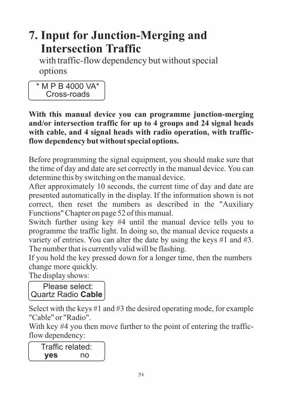
7. Input for Junction-Merging andIntersection Trafficwith traffic-flow dependency but without specialoptions
With this manual device you can programme junction-mergingand/or intersection traffic for up to 4 groups and 24 signal headswith cable, and 4 signal heads with radio operation, with traffic-flow dependency but without special options.
Before programming the signal equipment, you should make sure thatthe time of day and date are set correctly in the manual device. You candetermine this by switching on the manual device.After approximately 10 seconds, the current time of day and date arepresented automatically in the display. If the information shown is notcorrect, then reset the numbers as described in the "AuxiliaryFunctions" Chapter on page 52 of this manual.Switch further using key #4 until the manual device tells you toprogramme the traffic light. In doing so, the manual device requests avariety of entries. You can alter the date by using the keys #1 and #3.The number that is currently valid will be flashing.If you hold the key pressed down for a longer time, then the numberschange more quickly.The display shows:
Select with the keys #1 and #3 the desired operating mode, for example"Cable" or "Radio".With key #4 you then move further to the point of entering the traffic-flow dependency:
* M P B 4000 VA*Cross-roads
Please select:Quartz Radio Cable
Traffic related:yes no
��
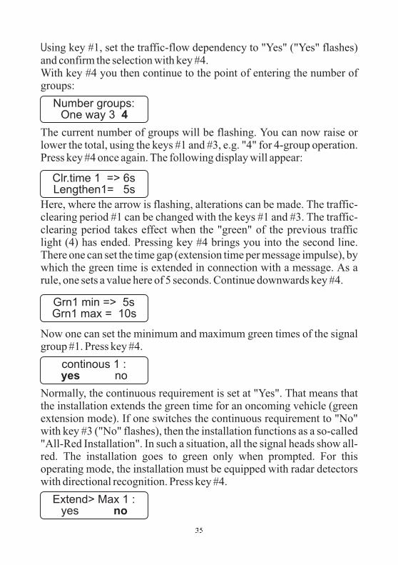
Using key #1, set the traffic-flow dependency to "Yes" ("Yes" flashes)and confirm the selection with key #4.With key #4 you then continue to the point of entering the number ofgroups:
The current number of groups will be flashing. You can now raise orlower the total, using the keys #1 and #3, e.g. "4" for 4-group operation.Press key #4 once again. The following display will appear:
Here, where the arrow is flashing, alterations can be made. The traffic-clearing period #1 can be changed with the keys #1 and #3. The traffic-clearing period takes effect when the "green" of the previous trafficlight (4) has ended. Pressing key #4 brings you into the second line.There one can set the time gap (extension time per message impulse), bywhich the green time is extended in connection with a message. As arule, one sets a value here of 5 seconds. Continue downwards key #4.
Now one can set the minimum and maximum green times of the signalgroup #1. Press key #4.
Normally, the continuous requirement is set at "Yes". That means thatthe installation extends the green time for an oncoming vehicle (greenextension mode). If one switches the continuous requirement to "No"with key #3 ("No" flashes), then the installation functions as a so-called"All-Red Installation". In such a situation, all the signal heads show all-red. The installation goes to green only when prompted. For thisoperating mode, the installation must be equipped with radar detectorswith directional recognition. Press key #4.
Clr.time 1 => 6sLengthen1= 5s
Grn1 min => 5sGrn1 max = 10s
continous 1 :yes no
Extend> Max 1 :yes no
Number groups:One way 3 4
��

Here you can choose whether an infinite extension of green time is to bepossible. If you select "Yes" (permanent green), then the green time willbe extended until an "opposing" traffic light is prompted by radardetector.
Continue with key #4.
Here you can set the number of signal heads on signal group #1. One canraise or lower the number of signal heads for the roadway signal headsin the first line, the number of pedestrian signal heads in the second.Pedestrian and roadway signal heads can also be mixed, so thatpedestrian installations can also be established without any problem.The maximum total number is 24 signal heads (4 with radio). Continuewith key #4.
If you select "Yes" during malfunction flashing, then the entire signalgroup shows "Yellow flashing" in the case of a malfunction (pedestriansignal heads are dark). Should you have altered the pre-setting to "No",then the entire signal group shows "Dark". Continue with key #4. Nowyou must enter the data for the signal groups #2, #3 and #4 in the sameway.
For this it is absolutely mandatory that the green-max.time #1 be at least 1 second larger than the green-min time for thisgroup.
Shead Gr1> 1Shead Gr1 0
F. blinking 1 :yes no
Clr.time 2 => 6sLengthen2= 5s
Grn2 min => 5sGrn2 max = 10s
continous 2 :yes no
Shead Gr2> 1Shead Gr2 0
F. blinking 2 :yes no
��

The entries for the signal groups 3 and 4 are carried out analogously, asdescribed above. Continue with key #4.
After the formulation of the signal plan, the display switches to thefollowing message:
Plug the device into the traffic light #1. Switch on the traffic light. Thetraffic light display shows:
Press# key #4. The data from the hand device will be transmitted to thetraffic light. The display in the manual device shows:
With radio or cable operation, you only need programme traffic signal#1 with the manual device. After you have wired the installation, or inthe case of a radio installation, simply switch the other traffic lights on,
.
Manual device: Control device:
one after the other
Makingsignalplan
Put box intoUnit 1 >4<
12,8 V Light ??No data !
��
12,8 V Light 1Light 2 missing !
Sending to lightDatablock: 159 /
12,8 V Light 1Receiving /
Transmission>> OK <<
Transmission>> OK <<
1 light correctprogrammed

The switching-on sequence of the signal heads determines therelationship to the signal groups with the corresponding number ofsignal heads per group.
Manual Options:
Not until the last signal head is switched onand the data has been transmitted via radio or cable does the installationstart up automatically through the switching-on programme.
(Flashing, Lights Off, All-Red and Programme Selection)The procedural methods with manual options can be found in Chapter V"Auxiliary Functions", on page 52 of this manual.
Warning: In the event of a data loss at traffic light #1 or #2 (throughactivation of the on/off switch), the entire installation must be re-programmed in the case of a .radio signal installation
��
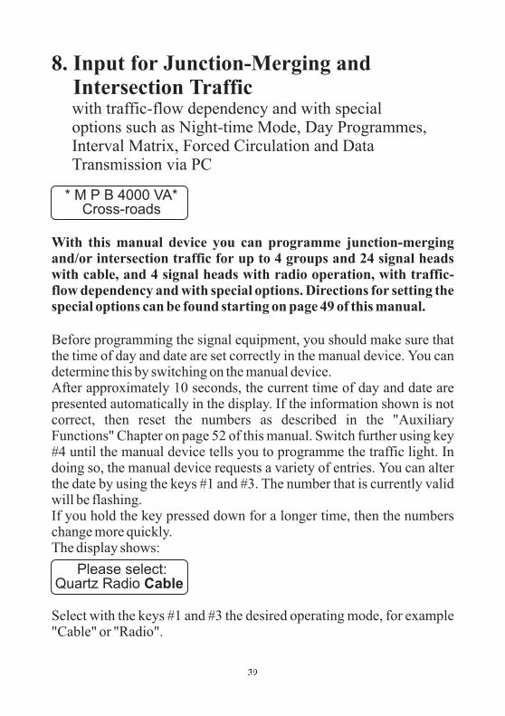
8. Input for Junction-Merging andIntersection Trafficwith traffic-flow dependency and with specialoptions such as Night-time Mode, Day Programmes,Interval Matrix, Forced Circulation and DataTransmission via PC
With this manual device you can programme junction-mergingand/or intersection traffic for up to 4 groups and 24 signal headswith cable, and 4 signal heads with radio operation, with traffic-flow dependency and with special options. Directions for setting thespecial options can be found starting on page 49 of this manual.
Before programming the signal equipment, you should make sure thatthe time of day and date are set correctly in the manual device. You candetermine this by switching on the manual device.After approximately 10 seconds, the current time of day and date arepresented automatically in the display. If the information shown is notcorrect, then reset the numbers as described in the "AuxiliaryFunctions" Chapter on page 52 of this manual. Switch further using key#4 until the manual device tells you to programme the traffic light. Indoing so, the manual device requests a variety of entries. You can alterthe date by using the keys #1 and #3. The number that is currently validwill be flashing.If you hold the key pressed down for a longer time, then the numberschange more quickly.The display shows:
Select with the keys #1 and #3 the desired operating mode, for example"Cable" or "Radio".
* M P B 4000 VA*Cross-roads
Please select:Quartz Radio Cable
�

W
N
ith key #4 you then move further to the point of entering the traffic-flow dependency:
Using key #1, set the traffic-flow dependency to "Yes" ("Yes" flashes)and confirm the selection with key #4. With key #4 you then continue tothe point of entering the number of groups:
The current number of groups will be flashing. You can now raise orlower the total, using the keys #1 and #3, e.g. "4" for 4-group operation.Press key #4 once again, and follow the display in the manual device. Ifyou have selected as a special option "Daytime Programme", thefollowing display will appear. The method used to activate the specialoptions is described in the annex under "Special Options".
Here, where the arrow is flashing, alterations can be made. The traffic-clearing period #1 can be changed with the keys #1 and #3. The traffic-clearing period takes effect when the "green" of the previous trafficlight (4) has ended. Pressing key #4 brings you to the next line. Thereone can set the time gap (extension time per message impulse), bywhich the green time is extended in connection with a message. As arule, one sets a value here of 5 seconds.This entry is carried out for traffic-clearing period + time gap 1, 2, 3 and4.
Continue downwards with key #4.
Now you will be called upon to enter the 1st daytime programme.
ow one can set the minimum and maximum green times of the signal
Traffic related:yes no
Number groups:One way 3 4
Clr.time 1 => 6sLengthen1= 5s
Input >4<Dayprogram 1
Grn1 min => 5sGrn1 max = 10s
�

group #1. Press key #4.
Normally, the continuous requirement is set at "Yes". That means thatthe installation extends the green time for an oncoming vehicle (greenextension mode). If one switches the continuous requirement to "No"with key #3 ("No" flashes), then the installation functions as a so-called"All-Red Installation". In such a situation, all the signal heads show all-red. The installation goes to green only when prompted. For thisoperating mode, the installation must be equipped with radar detectorswith directional recognition. Press key #4.
Here you can choose whether an infinite extension of green time is to bepossible. If you select "Yes" (permanent green), then the green time willbe extended until an "opposing" traffic light is prompted by radardetector.
Continue with key #4.
Here you can set the number of signal heads on signal group #1. One canraise or lower the number of signal heads for the roadway signal headsin the first line, the number of pedestrian signal heads in the second.Pedestrian and roadway signal heads can also be mixed, so thatpedestrian installations can also be established without any problem.The maximum total number is 24 signal heads (4 with radio). Continuewith key #4.
If you select "Yes" during malfunction flashing, hen the entire signalgroup shows "Yellow flashing" in the case of a malfunction (pedestriansignal heads are dark). Should you have altered the pre-setting to "No",then the entire signal group shows "Dark". The entries for the other
For this it is absolutely mandatory that the green-max.time #1 be at least 1 second larger than the green-min time for thisgroup.
t
continous 1 :yes no
Extend> Max 1 :yes no
Shead Gr1> 1Shead Gr1 0
F. blinking 1 :yes no
��

groups proceeds analogously. Use key #4 to proceed to the next menu.
When you are carrying out a -programming, you have the opportunityof deleting old switch points that may be left over from a previousprogramming. For this, select "Yes", and confirm your choice with key#4.
Here the manual device will ask you for 1-4 switch points for theentered Daytime Programme #1.This means that once you have entered a Daytime Programme, you canhave it start itself as many as four times a day, at the different times thatyou select:
00:00 means in this connection no input. For midnight, you must enter24:00After entering the starting time, you will be called upon to specify thedays on which the programme is to be used.
If you have selected more than one Daytime Programme, then you willnow be called upon to enter these as described above (Enter DaytimeProgramme #2).
After this entry, you have the opportunity of determining the Night-timeMode, if you have activated it as described in the annex under "SpecialOptions":
If you select "Yes" here, then you will be called upon to programme theNight-time Mode:
re
Switchp. clear ?yes no
Switchp. 1 Pro 1Start:>06:00 Uhr
Select Daysall Mo-Fr Sa-So
Nightmode:yes no
Input >4<Nightprog. darkl
��
H
U
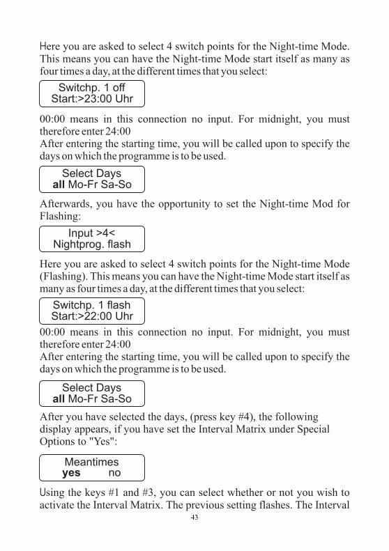
ere you are asked to select 4 switch points for the Night-time Mode.This means you can have the Night-time Mode start itself as many asfour times a day, at the different times that you select:
00:00 means in this connection no input. For midnight, you musttherefore enter 24:00After entering the starting time, you will be called upon to specify thedays on which the programme is to be used.
Afterwards, you have the opportunity to set the Night-time Mod forFlashing:
Here you are asked to select 4 switch points for the Night-time Mode(Flashing). This means you can have the Night-time Mode start itself asmany as four times a day, at the different times that you select:
00:00 means in this connection no input. For midnight, you musttherefore enter 24:00After entering the starting time, you will be called upon to specify thedays on which the programme is to be used.
After you have selected the days, (press key #4), the followingdisplay appears, if you have set the Interval Matrix under SpecialOptions to "Yes":
sing the keys #1 and #3, you can select whether or not you wish toactivate the Interval Matrix. The previous setting flashes. The Interval
Switchp. 1 offStart:>23:00 Uhr
Select Daysall Mo-Fr Sa-So
Input >4<Nightprog. flash
Switchp. 1 flashStart:>22:00 Uhr
Select Daysall Mo-Fr Sa-So
Meantimesyes no
��

Matrix is an additional control function for monitoring the minimumtraffic-clearing periods.The Interval Time is the period of time between the end of the greenphase (e.g. of traffic light #1) and the beginning of the clear signal(green) for a coming traffic flow that intersects or merges (e.g. traffic
light #2). [Direct interval times (from 1 2, for example) are takendirectly from the traffic-clearing time entries and take precedence.
They cannot be altered. Indirect intervals times (from 1 3, forexample) must be entered.]After selection of the Interval Matrix, the following display appears:
The prescribed time is automatically taken from the traffic-clearingtime and cannot be altered!Confirm the prescribed value using key #4. Now the display appears forsetting the interval from traffic light #1 to traffic light #3:
You must undertake the settings for all interval times as describedabove. Once you have finished the entries, press key #4 once again.
The display shows:
After the formulation of the signal plan, the display switches to thefollowing message:
Plug the device into the traffic light #1. Switch on the traffic light. Thetraffic light display shows:
Press key #4.
=>
=>
from 1 => 210 sec
from 1 => 310 sec
Makingsignalplan
Put box intoUnit 1 >4<
12,8 V Light ??No data !
��

The data from the hand device will be transmitted to the traffic light.The display in the manual device shows:
With radio or cable operation, you only need programme traffic signal#1 with the manual device. After you have wired the installation, or inthe case of a radio installation, simply switch the other traffic lights on,
.
Not until the last signal head is switched onand the data has been transmitted via radio or cable does the installationstart up automatically through the switching-on programme.
(Flashing, Lights Off, All-Red and Programme Selection)The procedural methods with manual options can be found in Chapter V"Auxiliary Functions", on page 52 of this manual.
Manual device: Control device:
one after the otherThe switching-on sequence of the signal heads determines therelationship to the signal groups with the corresponding number ofsignal heads per group.
Manual Options:
Warning: In the event of a data loss at traffic light #1 or #2 (throughactivation of the on/off switch), the entire installation must be re-programmed in the case of a .radio signal installation
��
12,8 V Light 1Light 2 missing !
Sending to lightDatablock: 159 /
12,8 V Light 1Receiving /
Transmission>> OK <<
Transmission>> OK <<
1 light correctprogrammed

9. Reprogramming or changing timesettings in radio/cable signallingequipment that has already been put intooperation.
With the new software version of our MPB 4000 traffic signalsystem you can carry out modifications to the radio/cable signallingequipment without having to switch off the signal system first. Thesignal system switches automatically to "all-red" duringreprogramming and, after reprogramming is completed, switchesautomatically back to automatic operation.
Follow this procedure:
Use the manual programming device to correct/modify the requiredtimes or other data for your construction measures. Apart from the basicentries, such as:
- Number of groups,- Number and type of signal heads (motor
vehicle/pedestrian),- Mode of operation radio/cable,
all information and data can be modified. When all entries arecompleted, the manual programming device shows the followingdisplay (already seen in previous programming):
Once the signal plan has been created, the display changes to thefollowing:
or
Now plug the manual programming device into operatingor (if traffic light 1 is operating with more than one
signal head).Press key 4 on the manual programming device.
H.10.10
traffic light1 traffic light 1K1
Makingsignalplan
Put box intoUnit 1 >4<
Put box intoUnit 1K1 >4<
��
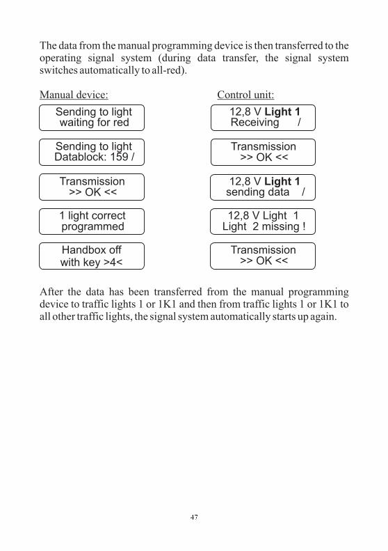
The data from the manual programming device is then transferred to theoperating signal system (during data transfer, the signal systemswitches automatically to all-red).
After the data has been transferred from the manual programmingdevice to traffic lights 1 or 1K1 and then from traffic lights 1 or 1K1 toall other traffic lights, the signal system automatically starts up again.
Manual device: Control unit:
12,8 V Light 1Light 2 missing !
Sending to lightwaiting for red
Sending to lightDatablock: 159 /
12,8 V Light 1Receiving /
12,8 V Light 1sending data /
Transmission>> OK <<
Transmission>> OK <<
Transmission>> OK <<
1 light correctprogrammed
Handbox offwith key >4<
��

III. Special Options with Quartz Operation
In order to reach the Menu items with special options, press key #2several times after switching on the manual device.
Before putting the night-time mode function into operation, you shouldmake sure that the time of day and date are set correctly in the manualdevice. You can determine this by switching on the manual device.
After approximately 10 seconds, the current time of day and date arepresented automatically in the display.If the information shown is not correct, then reset the numbers asdescribed in the "Auxiliary Functions" Chapter of this manual. Switchthe manual device on. Press key #2 several times, until the followingdisplay appears:
You can activate the night-time mode at this point in the display. Youcan move back and forth in the familiar way using keys #1 and #3. Oncethe night-time mode has been activated, the input prompt for the night-time mode will appear in the course of the programming. You thenproceed as described in the course of the directions for operation.
Night-time Mode
Nightmode:yes no
��

IV. Special Options with Radio or CableOperation
In order to reach the Menu items with special options, press key #2several times after switching on the manual device.
Before putting the night-time mode function into operation, you shouldmake sure that the time of day and date are set correctly in the manualdevice. You can determine this by switching on the manual device.
After approximately 10 seconds, the current time of day and date arepresented automatically in the display.If the information shown is not correct, then reset the numbers asdescribed in the "Auxiliary Functions" Chapter of this manual. Switchthe manual device on. Press key #2 several times, until the followingdisplay appears:
You can activate the night-time mode at this point in the display. Youcan move back and forth in the familiar way using keys #1 and #3. Oncethe night-time mode has been activated, the input prompt for the night-time mode will appear in the course of the programming. You thenproceed as described in the course of the directions for operation.
Night-time Mode
Nightmode:yes no
�

Daytime Programme
Interval Matrix
Neither the use nor the activation of daytime programmes is possiblewith quartz operation.Before setting the daytime programme, you should make sure that thetime of day and date are set correctly in the manual device. You candetermine this by switching on the manual device. After approximately10 seconds, the current time of day and date are presented automaticallyin the display.If the information shown is not correct, then reset the numbers asdescribed in the "Auxiliary Functions" Chapter starting on page 52 ofthis manual. Switch the manual device on. Press key #2 several times,until the following display appears:
The pre-set value is flashing. Using the keys #1 and #3, you can selectup to 4 daytime programmes. After you have selected the number ofdaytime programmes, continue to programme the installation asdescribed in the course of the directions for operation.
The interval matrix is an auxiliary control function for monitoring theminimum traffic-clearing periods. The interval is the amount of timebetween the end of the green phase (e.g. of traffic light #1) and the startof the clear signal (green) for a subsequent intersecting or mergingtraffic flow (e.g. traffic light #2).You have the opportunity of activating the interval matrix:
The pre-set value is flashing. You can select the setting using the keys#1 and #3.
Dayprograms:1 2 3 4
Meantimesyes no
�

Forced Circulation
Expect Data from PC...
Forced circulation serves the purpose of putting an emergencycirculation into effect in cases of failure of radar movement detectors orantennae. Forced circulation is useful only in conjunction with a traffic-dependency-operated All-Red installation or installations that operatewith green-on-demand features for side streets, for example. As anexperiment, enter "Yes" in the Menu "Traffic-dept." using key #1("Yes" flashes). Then go back using key #2 until the following Menuappears:
You can alter the value here with the keys #1 and #3 where the arrow isflashing. You go up one line using key #2. There you can switch to"Yes" using key #1 and "No" using key #3. The forced circulation isthus activated or not after each of the times set. This entry window willcontinue to be present until the setting for traffic dependency isswitched back to "No".
With this function, the opportunity exists of entering data from a PC viainterface. This option is explained in extra operating instructions for PCprogramming
To exit the special options menu items, press key #4 several times.This will then take you back to the programming proceduresdescribed in this operating manual.
Fail-safe: yesevery> 5 minutes
��
V. Auxiliary Functions
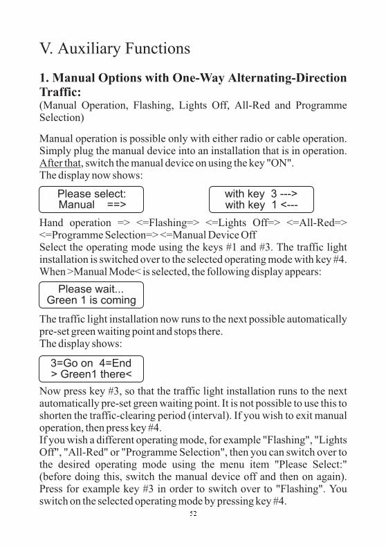
1. Manual Options with One-Way Alternating-DirectionTraffic:(Manual Operation, Flashing, Lights Off, All-Red and ProgrammeSelection)
Manual operation is possible only with either radio or cable operation.Simply plug the manual device into an installation that is in operation.
, switch the manual device on using the key "ON".The display now shows:
Hand operation => <=Flashing=> <=Lights Off=> <=All-Red=><=Programme Selection=> <=Manual Device OffSelect the operating mode using the keys #1 and #3. The traffic lightinstallation is switched over to the selected operating mode with key #4.When >Manual Mode< is selected, the following display appears:
The traffic light installation now runs to the next possible automaticallypre-set green waiting point and stops there.The display shows:
Now press key #3, so that the traffic light installation runs to the nextautomatically pre-set green waiting point. It is not possible to use this toshorten the traffic-clearing period (interval). If you wish to exit manualoperation, then press key #4.If you wish a different operating mode, for example "Flashing", "LightsOff", "All-Red" or "Programme Selection", then you can switch over tothe desired operating mode using the menu item "Please Select:"(before doing this, switch the manual device off and then on again).Press for example key #3 in order to switch over to "Flashing". Youswitch on the selected operating mode by pressing key #4.
After that
Please select:Manual ==>
with key 3 --->with key 1 <---
Please wait...Green 1 is coming
3=Go on 4=End> Green1 there<
��

The manual device display shows:
The installation runs automatically to the switch point set internally andswitches then to "Flashing".The manual device now shows:
Remove the manual device from the control unit and switch it off asshown by twice pressing key #4.
If you would like to switch back to "Automatic", then proceed asfollows: plug the manual device into one of the control devices (itdoesn’t matter which one). switch the manual device on.The manual device then displays the current operating mode of theinstallation in operation. In this example: "Flashing”
Switch back with key #4 to automatic mode. Afterwards you will becalled upon to switch the manual device off.
Entering programme selection proceeds as follows: plug the manualdevice into . , switch the manual device onusing the key "ON". Select the operating mode using keys #1 and #3.The traffic light installation switches over using key #4 to the selectedoperating mode. The display now shows:
Please select:Pro 1Pro 2Pro 3Pro 4Pro 7 (Off)Pro 8 (Flashing)
Then
traffic light #1 After that
Please wait...>Flashing coming
>Flashing thereAutomatic >4<
Please select:>-< Pro 1 >+<
��
>Flashing thereAutomatic >4<
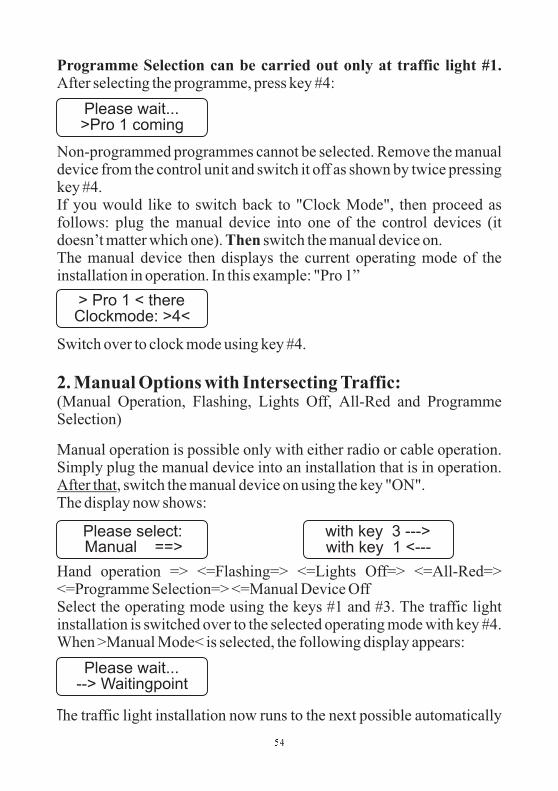
Programme Selection can be carried out only at traffic light #1.
Then
After selecting the programme, press key #4:
Non-programmed programmes cannot be selected. Remove the manualdevice from the control unit and switch it off as shown by twice pressingkey #4.If you would like to switch back to "Clock Mode", then proceed asfollows: plug the manual device into one of the control devices (itdoesn’t matter which one). switch the manual device on.The manual device then displays the current operating mode of theinstallation in operation. In this example: "Pro 1”
Switch over to clock mode using key #4.
(Manual Operation, Flashing, Lights Off, All-Red and ProgrammeSelection)
Manual operation is possible only with either radio or cable operation.Simply plug the manual device into an installation that is in operation.
, switch the manual device on using the key "ON".The display now shows:
Hand operation => <=Flashing=> <=Lights Off=> <=All-Red=><=Programme Selection=> <=Manual Device OffSelect the operating mode using the keys #1 and #3. The traffic lightinstallation is switched over to the selected operating mode with key #4.When >Manual Mode< is selected, the following display appears:
he traffic light installation now runs to the next possible automatically
2. Manual Options with Intersecting Traffic:
After that
T
Please wait...>Pro 1 coming
> Pro 1 < thereClockmode: >4<
Please wait...--> Waitingpoint
��
Please select:Manual ==>
with key 3 --->with key 1 <---

pre-set green waiting point and stops there.The display shows:
Now press key #3, so that the traffic light installation runs to the nextautomatically pre-set green waiting point. It is not possible to use this toshorten the traffic-clearing period (interval). If you wish to exit manualoperation, then press key #4.If you wish a different operating mode, for example "Flashing", "LightsOff", "All-Red" or "Programme Selection", then you can switch over tothe desired operating mode using the menu item "Please Select:"(before doing this, switch the manual device off and then on again).Press for example key #3 in order to switch over to "Flashing". Youswitch on the selected operating mode by pressing key #4.The manual device display shows:
The installation runs automatically to the switch point set internally andswitches then to "Flashing".The manual device now shows:
Remove the manual device from the control unit and switch it off asshown by twice pressing key #4.
If you would like to switch back to "Automatic", then proceed asfollows: plug the manual device into one of the control devices (itdoesn’t matter which one). switch the manual device on.The manual device then displays the current operating mode of theinstallation in operation. In this example: "Flashing”
Switch back with key #4 to automatic mode. Afterwards ou will becalled upon to switch the manual device off.
Then
y
��
3=Go on 4=End>Waitingpoint<
Please wait...>Flashing coming
>Flashing thereAutomatic >4<
>Flashing thereAutomatic >4<

Simply plug the manual device into an installation that is in operation., switch the manual device on using the key "ON".
The display now shows:
Please select:Pro 1Pro 2Pro 3Pro 4Pro 7 (Off)Pro 8 (Flashing)
After selecting the programme, press key #4:
Non-programmed programmes cannot be selected.Remove the manual device from the control unit and switch it off asshown by twice pressing key #4.
If you would like to switch back to "Clock Mode", then proceed asfollows: plug the manual device into one of the control devices (itdoesn’t matter which one). switch the manual device on.The manual device then displays the current operating mode of theinstallation in operation. In this example: "Pro 1”
Switch over to clock mode using key #4.
First switch the manual device off. Then, while holding key #1 presseddown, switch the manual device on (brief pressure on key "On").After ca. 10 seconds, release key #1. By using keys #1 and #3, thevalue marked with "> <" can be raised and lowered. One proceeds to
After that
Programme Selection can be carried out only at traffic light #1.
Then
3. Setting Date and Time
��
Please select:>-< Pro 1 >+<
Please wait...>Pro 1 coming
> Pro 1 < thereClockmode: >4<

the setting of the next value with key #4. When one presses key #4 oncemore after setting the seconds value, the internal clock will be set withthe values that have just been selected.Remark: a correctly-set clock is important if the data from a trafficsignal installation are to be printed out or if the daytime programme orthe night-time mode is activated. This ensures that the logs thusassembled are equipped with the right date and the correct time of day.The daytime programme and the night-time mode will also thus beautomatically switched on at the right time.
First switch the manual device off. Switch the manual device on, usingthe key "On"; the following message appears in the display:
The installed software version appears then in the first line and the serialnumber of the manual device in the second.
4. Version Display in Manual Device
*PeterBerghaus** Traffic Light *
Vers. H1010 08:40Handbox: 685
��

5. Acknowledging errors
If the manual device is plugged into a flashing installation and thenswitched on, as though one wished to operate the installation manually,and the above message appears, then the installation had an error (forexample, green-green violation).In such cases, the message in the traffic light display is to be followed.That is where the error is more precisely described. An attempt can bemade to acknowledge the error using key #4.Should the installation still not start up after that, then thecorresponding error must be eliminated.
Quit Failurewith key >4< !
��

6. Special Operation modes using internal and external rotaryswitches for manual options, such as manual operation, flashing,lights off and all-red
For example: manual operation
6.1. Setting special operating modes by means of built-in rotaryswitches (optional)
(only possible with cable and radiocontrol)Set the rotary switch to manual operation; after approximately 5seconds the red LED flashes. This means that the special operatingmode you selected has been activated. If the red LED changes fromflashing red to a continuous red light, the signal system is in the nextpossible green waiting point. By pressing the key, the signal systemmoves to the next green waiting point of the following signal group.When the key is pressed, the LED flashes red; when the next greenwaiting point is reached, the LED is again a continuous red light. It istherefore not possible to use this to shorten the traffic-clearing period(time interval). The sequence and current status of the individual signalgroups can be observed on the traffic light display.
If you wish to exit manual operation, turn the rotary switch from manualoperation back to automatic. The red LED switches itself off afterapproximately 5 seconds showing that the signal system has switcheditself back to automatic operation.If you wish to have further special operating modes, such as flashing,lights off and all-red, follow this procedure:Turn the rotary switch from automatic to the desired special operatingmode, e.g. flashing. After approximately 5 seconds, the red LED
PUSH BUTTON
AUTOMATIC
MANUALCONTROL
FLASHING
LAMPS OFF
ALLRED
EXTERN
�������� �
�
flashes indicating that the special operating mode you selected has beenactivated. The signal system now operates until the preset switch-offtime and then switches via a switch-off display to yellow flashing.(Please note that the only motor vehicle groups that flash are those thathave been programmed with "yes" in the "Error flashing" menu item;pedestrian signal heads automatically have a dark display.) The LEDlights up continuously when the selected special operating mode hasbeen reached.If you wish to exit the selected special operating mode (yellowflashing), turn the rotary switch back to automatic. The red LED turnsitself off after approximately 5 seconds and the signal systemautomatically switches back to automatic operation via an activationprogram.
6.2. Setting special operating modes by means of external cable remotecontrol (optional)
1. Set the rotary switch of the (optional) built-in manual control tothe position “extern”.
2. Choose the desired special operation mode by means of therotary-switch on the external cable remote control.
3. Open the cap of the connector for the external cable remotecontrol below the control chamber of the traffic light.
4. Connect the plug of the cable remote control to the connector ofthe traffic light and fasten it by turning around the nut of theplug.
5. After approx. 5 seconds the chosen special operation modewould be activated. The further steps for choosing the differentspecial operation modes you could find in chapter 6.1 on thepages before.
�

Common comments
Attention:
If several signal heads are modified with this accessory equipment, youhave to be sure that the use would be made only at one signal head. Onall other signal heads the rotary-switches have to stay in position“Automatic”.Should one rotary-switch unnoticed not stay on “Automatic”-position,the red function-LED will show a fast blinking indication. This means amalfunction and the traffic light could not execute the chosen mode.Please, check which rotary-switch is not in the “Automatic”-positionand bring him into the right position(Automatic). Now, after approx. 5seconds, the chosen special operation mode would be activated.
It is not possible to choose the special operation mode“Flashing” and “Lamps Off” directly while staying in the specialoperation modes “Manual operation” or “Allred”. Hereby it isnecessary to choose first the special operation mode “Automatic” andafterwards the desired special operation mode (Flashing or Lamps Off).A direct change between the other special operation modes is possible.
��

VI. Control Device
VI.1 Switching Control Device On and Off- Changingthe Storage Batteries
The control device is equipped with only an On/Off switch and a fuse.
The maximum allowed value of the fuse is 6.3 A!
In order to put the installation into operation, the first thing is to(being careful to ensure correct
polarity!) Switch on the traffic light using the main switch. The trafficlight display will now automatically show the manufacturer and theEPROM version:
After this automatically-appearing message, the display should showthe following:
The control unit can be re-programmed only in conjunction with thedisplay "Expect Data"!
After successful programming, the signal head sends a message withthe respective traffic light number.
clampon the storage battery in the battery box
*PeterBerghaus** Traffic Light *
Epromversion:H1010 08:40
12,8 V Light ??No data !
��

The display appears as follows:
Should the installation be malfunctioning, then a clear description ofthe error will be displayed in the second line.
or
If the installation is switched off for 10 seconds or more, then all datawill be lost! The traffic light will then have to be re-programmed.
Should the storage battery voltage fall below ca. 11 Volts duringoperation, a corresponding warning will appear in the display of thecontrol device, when it is set for quartz operation.Should the equipment be linked by either wiring or radio, then one cansee at every signal head where the storage batteries need to be changed(see also at Error Description).The following message appears:
Warning:
All data are retained while changing storage batteries.
12,8 V Light 110s Red
Voltage or programme or time of day Traffic light number and signal configuration
light statuscirculation second
only with traffic actuated operation+ = message
= demand stored in memory
12,8 V Light 1Light 2 missing !
12,8 V Light 1K1Light 1K2 missing !
*Accu change !*10 V
��

VI.2 Error Messages for Control Device
The error messages of the control device are displayed in the lower lineof the LED display. The error display is very user-friendly. Allcurrently-active errors are displayed, one after the other, using cleardesignations in slow succession to one another.In the cases of cable and radio installations, not just the errors of theindividual equipment are displayed, but also those present at othertraffic lights. When you are summoned to a malfunctioning installation,open at random a control device cover. There you will see for examplein the display "Red 2 defective".The displayed text speaks for itself. Proceed to traffic light #2 andoverhaul the red light.The installation will then return by itself to programme flow.
An attempt has been made to programme a new control device with anold manual device, or vice-versa (different EPROM versions).Remedy: contact us and request the current version number.
The control device has a malfunction.Switch the control unit off and then on again. Normally, this shouldremove the malfunction. If this is not the case, please send the controlcard to the factory for repair.
The red lamp at traffic light #2 is defective and must be replaced. Afterelimination of the error, the installation starts up again automatically. Ifthe traffic light is fitted with LED-modules you have to quitt the failureas described on page 58.
This is a status error. Yellow or red status errors can also occur. In this
WRONG VERSION !
*INTERNAL FAILURE
12,8 V Light 1Red defect 2
12,8 V Light 1Green status 3
��

case of this error, the directive to the control does not conform to theactual task at hand. Acknowledge the error using the manual device.Should the error re-occur, then you must send the control panel to thefactory for evaluation.
In the case of this error, for example, the signal groups #1 and #3 wouldbe transmitting an "opposing" signal configuration not allowed in theprogram (in this example, both groups showed green simultaneously).The green-green monitoring prevents the two groups from actuallydisplaying simultaneously green.In order to determine the cause of the malfunction, you must nowinspect groups #1 and #3. The group which shows a status error (greenstatus) is the source of the malfunction.Acknowledge the error with the manual device. If the error reappears,then you must send the control panel to the factory for evaluation.
In the case of this error, there is an interval error between groups #2 and#3. Check the input of your green and interval times for groups #2 and#3. Correct the times and re-programme the installation.
In the case of this error, the transmission is being disrupted by the radioor cable line. In the example shown, traffic light #2 is affected. Causesfor this could include:
with radio operation: Antenna beamers defective or missing Radiomodule defective or plug connection loose
with cable operation: Cable connection defectivePlug connection loose
fter elimination of the error, the installation automatically resumes theprogramme. The error need not be acknowledged with the manualdevice.
A
12,8 V Light 1E. Gr. Grp. 1/3
12,8 V Light 1Meant. Grp. 3/2
12,8 V Light 1No Rec. Light 2
��
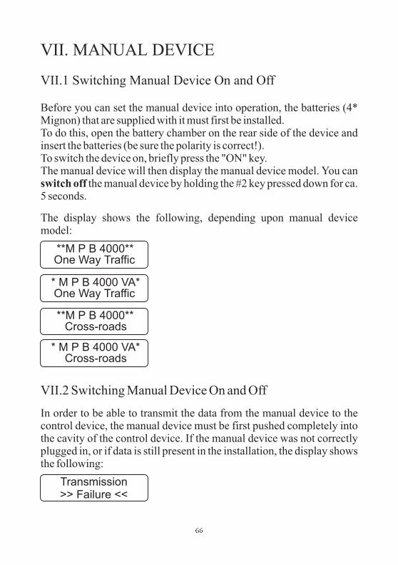
VII. MANUAL DEVICE
VII.1 Switching Manual Device On and Off
VII.2 Switching Manual Device On and Off
Before you can set the manual device into operation, the batteries (4*Mignon) that are supplied with it must first be installed.To do this, open the battery chamber on the rear side of the device andinsert the batteries (be sure the polarity is correct!).To switch the device on, briefly press the "ON" key.The manual device will then display the manual device model. You can
the manual device by holding the #2 key pressed down for ca.5 seconds.
The display shows the following, depending upon manual devicemodel:
In order to be able to transmit the data from the manual device to thecontrol device, the manual device must be first pushed completely intothe cavity of the control device. If the manual device was not correctlyplugged in, or if data is still present in the installation, the display showsthe following:
switch off
**M P B 4000**One Way Traffic
* M P B 4000 VA*One Way Traffic
Transmission>> Failure <<
**M P B 4000**Cross-roads
* M P B 4000 VA*Cross-roads
��

Repeat the transmission with key #2 or cancel it with key #4. Normallythe manual device will show the following:
with cable and radio:
Switch the device off using key #4. The manual device disconnectsautomatically after 10 minutes, if during that time no key has beenactivated.
When this error message appears, one can still continue to work for atime. It is however to be recommended that a new set of batteries beinstalled.
The manual device has a function error. Remove -- while this errormessage is being displayed -- the batteries from the manual device.Replace them and switch the manual device on again. Normally, theerror should then be eliminated. If not, please forward the manualdevice for repair.
The device must be sent in for examination.
Warning: Please switch off the manual device before replacing thebatteries. (Do not use rechargeable storage batteries)
Send again ?<2>=Yes <4>=No
Handbox offwith key >4<
Batteries empty..Please change !
Internal Failure:unknown menu
Box defect !Please switch off
Set clockGo on with >4<
��
1 light correctprogrammed
2 lights correctprogrammed

T
T
he factory settings for date and time of day have been lost. Afterpressing key #4, a menu will be displayed with which the current timecan be entered (for this see the chapter "Auxiliary Functions", startingon page 52).After the correct setting of the internal clock has been made, this specialmenu will not be displayed again.
An error has been detected during data input. A prescribed programmeflow can not be accomplished with the data as entered. Please check thedata.
While entering the roadway -- or pedestrian signal heads, more than 24signal heads were entered. Please correct the erroneous input.
If for example settings were made for 3 groups, and then the number ofsignal heads was set to "Zero" for group #1, then this error message willbe displayed. Remedy: Should for any reason groups be operatingwithout signal heads, then these always must be the groups in theseries: for example, with 4 groups, the least two are set to be "signalhead-less" (signalg.: roadway, pedestrian=0).
This messages is displayed with the minimum green time for group #1has not been met. The set green time of a group has been entered at lessthan 5 seconds. The green time selected is not to be less than 5 seconds,according to RiLSA. You must change the value for group #1.
his message is displayed when there is a green-time overlap between 2or more signal groups (both or more than two display greensimultaneously).
last
Please checkthe data....
To manySignalheads !!
Group ? withoutheads !!
Green min 1too small !
!! Greentimes !!!! overlaping !!
��

As this can easily be so intended, you have the opportunity ofconfirming the message with key #3. This message is to be consideredmerely a warning.
If the above message appears after the manual device has been pushedinto a flashing installation and then switched on, as if one had wanted tooperate the installation by hand, then the installation has an error(green-green violation, for example).In such cases the message in the traffic light display is to be consulted.The error will be described in greater detail there. An attempt can bemade to first acknowledge the error using key #4.Should the installation still not start up, then the corresponding errormust be eliminated.
Quit Failurewith key >4< !
�

VIII. Accessories for MPB 4000
• Radio retrofitting
• Retrofitting for traffic-dependent operation
• Monitoring printer
• Interface for printer (4 groups)
• Interface for PC (laptop) programming (12 groups)
• Software for PC (laptop) programming
• Pedestrian symbols for signal heads
• Pedestrian demand tracer
• Installation external manual operation for signal head
• Operating device for external manual operation
• Internal manual operation for signal heads
• Retrofitting set for changeover to 42 V operation
• Installation parallel box for parallel signal heads
• Parallel signal heads
• Retrofitting for second red light
• Anti-theft protection for signal heads
• LED-modules for red / yellow / green
�

IX. Technical Data
Operating voltage: approx. 9 - 14 V DC
Voltage use with quartz or cable operation
Daytime operation: ca. 1.20 A per signal head (Halogen)Daytime operation: ca. 0.48 A per signal head (LED)Night-time operation: ca. 0.81 A per signal head (Halogen)Night-time operation: ca. 0.32 A per signal head (LED)
Voltage use with radio operation
Daytime operation: ca. 1.40 A per signal head (Halogen)Daytime operation: ca. 0.68 A per signal head (LED)Night-time operation: ca. 1.10 A per signal head (Halogen)Night-time operation: ca. 0.58 A per signal head (LED)
Light sources: 12 V / 10 W halogens with G4threads (industry standard)Optional the traffic light could befitted with LED-modules
Fuses: 6.3 A, 5 x 20, semi-time lag(industry standard)
Operating modes: Fixed-period, traffic-dependentoperation, traffic-dependentoperation with green on demand(each with 4 daytime programmes)and manual operation
Data transmission: Quartz, cable, digital spark gap
Radio distance: max. length under ideal conditions:2000m
��

Radar DetectorMWD BF
Description
1. General
The MWD BF is a directional recognition radar detector which wasconceived specifically for use in the area of industrial gate and barrierinstallations.
The detection of movement proceeds in accordance with the DopplerPrinciple. For this the sensor sends out microwaves in the 24 GHzrange. These are altered in their frequency by moving objects. Thealtered frequencies are received by the sensor, which evaluates them.Thus, every movement within the radar detection field is registered,subsequently evaluated using a logical analysis and communicatedthrough a relay-output to the gate or locker control unit.
- One can choose between models with or without directionalrecognition
- Distinction can be made with directional recognition betweenapproaching and retreating
- Voltage-free relay output- Insensitivity to temperature and moisture variations, air currentsand radio disruptions
- Voltage supply either AC or DC- Sensitivity setting possible through opening in the front side ofthe housing
- Housing protected with the IP 65 Protection Type, and thusprotected in all directions against dust and water jets
- Cost-saving installation
Adjustment of operational parameters by key buttons or infraredremote control
- Compact plastic housing
The radar detector also offers other advantages:
-
��

2. Mounting
2.1 Place of installation
2.2 How to screw down the housing
The device is centtraly mounted above the sector to be monitored.
The maximum mounting height is approx. 6m.
- The device should be mounted at a point that is vibration-free.
- In order to avoid spurious release, there must not be
- There must not be within the radion field
of the detector.
- It should be avoided that the radion fields of two motion
detectors overlap, since this may lead to spurious releases.
- Do not install behind objects, building coverings or elements.
- If the radar detector is subject to rain or snow, then it should be
set to the directional recognition mode (one-directional -
retreating).
The cover should be screwed down with a torque of approx. 1 Nm.
Put the cover evenly into the groove of the housing and screw it
down.
Hints for planning and installation:
any
objects in motion within the radiation field.
any fluorescent tubes
If the cover is off straight, for example due to
squeezed cable leads in between the screw guides, the
tightness of the housing is impaired!
Attention!
�� ��� �� �� ������ ��� ��� �� ��� ������
��
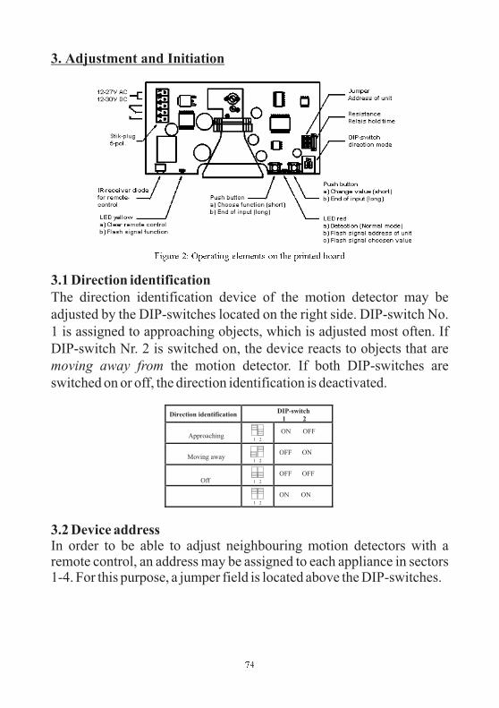
3. Adjustment and Initiation
�� ��� �� �������� �������� �� ��� ������� �����
3.1 Direction identification
3.2 Device address
The direction identification device of the motion detector may be
adjusted by the DIP-switches located on the right side. DIP-switch No.
1 is assigned to approaching objects, which is adjusted most often. If
DIP-switch Nr. 2 is switched on, the device reacts to objects that are
the motion detector. If both DIP-switches are
switched on or off, the direction identification is deactivated.
In order to be able to adjust neighbouring motion detectors with aremote control, an address may be assigned to each appliance in sectors1-4. For this purpose, a jumper field is located above the DIP-switches.
moving away from
��
Direction identificationDIP-switch
1 2
Approaching1 2
ON OFF
Moving away1 2
OFF ON
Off 1 2
OFF OFF
1 2
ON ON

3.3 LED display
3.4 Fall-delay time of relay
3.5 Personal suppression
The factory-alignment for the fall-delay time of the relay is 0,5 seconds.
An extension of the fall-delay time to 2 seconds may be reached by
removing the resistor, which is located next to the jumpers for the
device address (figure 2).
If personal suppression is activated, the appearance of single persons
will not trigger the device. For more information regarding adjustment
of personal suppression, please see section 3.6.2 resp. 3.7.3.
Personal suppression is designed for the use in typical internal traffic
situations at a shed gate. Deviating conditions (very low or high
mounting height, setting angle is too steep or too flat, oblique mounting
position) or untypical objects (e.g. fast moving persons, groups, very
slow vehicles, high-lift trucks with fabric rolls etc.) may lead to
Warning: The resistor may only be cut through in currentless
condition! Please make sure that no components or
strip conductors are damaged!
��
Address Jumper position
1
2
3
4
Mode of operation Yellow LED – left side Red LED – right side
Object recognition Off Object identified
Adjustment with key button Flash signals for function
numbers
Flash signals acc. to parameter
significance
Adjustment with remote control a) Reception readiness for
infrared remote control
b) Flash signals for function
numbers
a) Flash signals acc. to parameter
significance
b) Flash signals for device
address

malfunctions if personal suppression is activated.
Operational parameters (sensitivity, personal suppression) may beadjusted with the buttons located at the right side of the horn antenna.
If a function is selected for the first time, the function number isindicated on the yellow LED, followed by the currently set value on thered LED.The adjustment process is terminated automatically 30 seconds afterthe last button has been pressed or by pressing a button for a longer time.
The sensitivity of the motion detector may be adjusted by degrees from1 to 15. Each time the right button is pressed, the sensitivity is increasedby one degree. Degree 15 is followed by degree 1.
The personal suppression of the motion detector may be activated(position 1) and de-activated (position 2) by using the button on theright side.
In order to reset the parameters to the factory setting, both buttons arepressed while switching on power supply. Now, the followingadjustments are made:
3.6 Adjustment with key buttons
3.6.1 Selection of sensitivity
3.6.2 Personal suppression
3.6.3 Factory setting
Left button / yellow LED: select/indicate functionRight button / red LED: change/indicate value
Yellow LED flashes 1xRed LED flashes 1 x acc. to value of the current degree of
sensitivity
Yellow LED flashes 2xLED rot flashes 1x if personal suppression is activated
2x if personal suppression is de-activated
Degree of sensitivity: 7
��

Before the parameters of a motion detector can be changed with theremote control, the appliance has to be activated for this adjustment. Forthis purpose, please press the -key. Now, all motion detectors withinthe range of reception of the remote control will indicate the set deviceaddress on the red LED. If the address of the desired device is enteredwithin 3 seconds by the numeral keys of the remote control, theactivated device shows its readiness for entry on the yellow LED. Allother appliances are not activated and return to their normal mode.
After the device has been cleared, the sensitivity of the motion detectormay be changed with the keys and . When the keys are pressedfor the first time, the yellow LED indicates the number of the desiredfunction with flash signals. The adjusted value is indicated by flashsignals of the . Sensitivity ranges from 1 to 15.
Please switch off personal suppression when adjustingsensitivity.
The -key changes the setting of the personal suppression.
Personal suppression: off
Yellow LED flashes 1x (function 1)Red LED flashes 1 x acc. to value of current sensitivity
level
Yellow LED flashes 2x (function 2)Red LED flashes 1x if personal suppression is
switched on2x if personal suppression is
switched off
3.7 Adjustments with the optional infrared remote controlMWD RC
3.7.1 How to activate the adjustment mode
3.7.2 Selection of sensitivity
3.7.3 Personal suppression
red LED
Notice:
��
.

3.7.4 How to terminate the adjustment mode
3.8 Adjustment of the detection zone
Pressing the -key terminates adjustment with the remote control. Themotion detector now returns to the normal detection mode. The yellowLED is extinguished. The red LED now continues to indicate detectedobjects. The object recognition mode is automatically activated, if noentry has been made with the key buttons or remote control for 30seconds.
The MWD BF has a circular detection zone. Size and position of the
detection zone may be altered by adjusting sensitivity and inclination
angle. In general, the optimum inclination angle lies between 30° and
45°. In order to change the angle of radiation, please loosen the lateral
screws located between support bar and housing. On both sides of the
housing there are division marks in a 15° grid system.
The size of the detection zone may change depending on the size and
speed of the object to be detected. If the motion detector is mounted in a
height of more than 4 meters and sensitivity is low, the detection zone
for persons becomes very small.
5m
30°
��

4. Technical Data
Housing Dimensions (without cable) 132 x 155 x 58 mm
Colour black
Housing pot plastic ASA
Support bar plastic ASA
Cover plastic PC
Weight (incl. support bar) 0,3 kg
Protective system IP 65
Distribution voltage 12-27 V AC
12-30 V DC
Power draw Typ. 1,5 W
Max. 2,4 W
Admissible working temperature -20 °C to +55 °C
Storing temperature -30 °C to +75 °C
Air moisture < 95 % non fogging
Frequency 24,125 GHz
Transmitting power typ. 5 mW
Output relay
max. turn-on voltage 24 V AC/DC
max. switching current 1 A at resistive load
min. switching current 1 mA
Contact type 1 change-over contact (potential-free)
In case of inductive load please provide for an external
protective wiring or the relay contacts!
Connecting cable Flexible, max. 5x1,0 qmm
Fall-delay time of relay 0,5 s / 2 s, selection with jumper
Maximum mounting height 6 m
Adjustable functions By means of sliding switch on printed card
Direction recognition
off/approaching/moving away
By means of key button or infrared remote control
Sensitivity
Personal suppression
Factory setting (only key buttons)
CE-relevant standards ETS 300 683
�

5. Short survey
Operating elements and pin configuration:
Direction recognitionDIP-switches
1 2
Off1 2
1 2
OFF OFF
ON ON
Approaching1 2
ON OFF
Moving away1 2
OFF ON
Device address
for remote
control
Jumper
position
1
2
3
4
Remote control keyFunction
Flash signal of LED
Left rightAdjustment range
Acivation Ready Address 1 .. 4 (address)
/ Sensitivity 1x current value 1=low .. 15=high
Extraction of persons 2x current value 1=on 2=off
i - - -
�
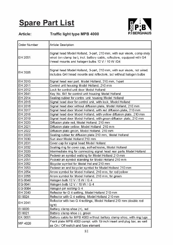
Spare Part List
Article: Traffic light type MPB 4000
�� ����
���� � � ��� � ������ ������ ��� ��� ���� �� ������� ����� � ��
��� � �� ���� �� � ���! ��� �� ��� � � "� ������ #���� � ���� $%
��� � ����� � ���� ����� �� & ' �� ( '$%
�� ���)���� � � ��� � ������ ������ ��� ��� ���� �� ������� �� ��� ��
����� � $% ��� � ����� � � "� ������ ��� ������� ���� �����
�� ���� ���� � � � � ���� ��� � ������ ��� ��� �����
�� ���� *����� ��� ������ ��� � ������ ��� ��
�� ���� +��, "�� ������ ��� ���� ��� � �����
�� �-%� . � /�! -%� "�� ������ ��� ������ ��� � �����
�� ���% � ��� ���� � "�� ������ ��� ������ ��� � �����
�� ���) ���� � � ���� "�� ������ ���� ���� ���,� ��� � �����
�� ���- ���� � � ���� ������� ��""���� ��� � ��� � ������ ��� ��
�� ���0 ���� � � ���� ��� � ������ ���� � � ��""���� ��� � ��� ��
�� ���1 ���� � � ���� ��� � ������ ���� � ���� ��""���� ��� � ��� ��
�� ���2 ���� � � ���� ��� � ������ ���� �� ��""���� ��� � ��� ��
�� ���� 3�""���� ��� � �� ��� � ������ ��� ��
�� ���� 3�""���� ��� � ����� ��� � ������ ��� ��
�� ���� 3�""���� ��� �� � ��� � ������ ��� ��
�� ���� � ��� ���� � "�� ��""���� ��� ��� ��� ��� � �����
�� ���� �� ����� ��� � ����� ��� ��
�� ���� *�� � �� "�� ���� � � ��� � �����
�� ���� � ��� ��� "�� ��� � ��� � �"��� ��� � ��� � �����
�� ���� 4� �� ��� ��� "�� �� ���� ���� � � � � ���� ��� � �����
�� ��)� 5 � ���� ������ ��,�� "�� ��� � ����� ��� ��
�� ��)� 5 � ���� ������ ����� "�� ��� � ����� ��� ��
�� ��)� 6����� � ������ "�� ��� � ����� ��� ��
�� ��)� 5 � ���� � ������ � ������ "�� ��� � ����� ��� ��
�� ��)% 7���� ������ "�� ��� � ������ ��� ��� "�� � �'� ����
�� ��)) 7���� ������ "�� ��� � ������ ��� ��� "�� ��
�$ ��%� ���� ���� �� & ' ) ( ' $ %
�$ ��%� ���� ���� �� & ' �� ( ' $ %
�$ ��1% ���� �� � ���� $ %
�� ��%� 8 "� ���� "�� $ % � ����� ��� � ����� ��� ��
�4 ���% 8 "� ���� ���� $ % � ����� ��� � ����� ��� ��
�� ��%�8 "� ���� ���� ��� $ % � ������ ��� � ����� ��� �� ������ � �
�����
�4 ���� 6�� �� ���� ��� �9 � � �
�4 ���� 6�� �� ���� ��� �� � ��
�. ���� 6�� �� ��� "�� �56 %��� ������� ��� �� ���� ��� � ���� ��� ����
�5 %��-:��� ��� �56 %��� �����! ���� �2 ��� �� �� � ���� ��� � � ��
� ; ' ;"" ������ � "�� � � �
;�� � /��� � 7����� 3 �������
81

Spare Part List
Article: Traffic light type MPB 4000
�� ���� ��� �� � ��� ���� ��� �� ��� ����
�� ���� � � ��� ����� � �
�� ���� ����! ��"# $ � ��� �� ��� ����
�� ���� �"�� ���%� ��� ���%" &� � ��'
�� ���� � ��( ��)�� ��� �"�� &� � ��'
�� ���� �"�� � � �� � �*�
�� ���� +�,,�# ����� ��� �����# � $�� ! ����� �������
��� ��� -���� "� �� � ��� ��� ����
��� ��� �� � ��� .�+ !���� (
�� ���� / !�� ��,��� ��!�� ��0+ �� ��� ��� ����
�� ���1 / ! � !����� �� 2 ���* �*� , � $�� ��� ,�"�! ��"#
�� ���� ��"�# $� �%� ��� � ! � !�����
�� ���� ��"�# $� �%� ��� � !�� � ! � ! � !�����
�� ���� � $� ,�� ����" ��#" ! �����
�� ���� 3�#" ! ����� ��� � $� ,��
�� ���� � � $�� ��� �4- ��"# ! ������ � �
�� ���� �0���� �"$0��"# ��� � !�� ��� ����
�� ���� �� #� ��"���# �0���� �25
�� ���� �� #� ��"���# 10���� �25
�� ���� #��! ��"# �0���� �25
�� ���� �� #� ��"# 10���� �25
�� ���� -����# � � ��� ��"# ! �� #� ��"# �25
�� ���� -����# � � ��� ��"���# ! �� #� ��"���# �25
�� ���6 7�"��# ��� , " � ���#� ,,�# !�)��� ��� ���� ����" ���� %�($� �!
��� ��� �� � ��� , " � ���#� ,,�# !�)���
�� ���� ���� %�($� �! ��� , " � ���#� ,,�# !�)���
�� ��1� �*� 2 $ ��( ��� , " � ���#� ,,�# !�)���
����� ��� #� $ ��( ������)� $�� � ��� #� $ ��(
�� ���� - ��� ���8 �"$$�� ��� ,,
�� ���� -�)���# � � ��� � ���
�� ���� ��"�# "$� # �) ���! ��� ��� ����
�� ���� 3�#����� � �� � ��
�� ���� 7�#�! ��"# ��� ��� #� $ ��( � ��
����� �����0�)�� ��������� ��� � ��� #� $ �����
����� �����0�)�� ��������� ��� � ��� #� $ �����
��!�� 4",$�� ����� +��������
82

83

84
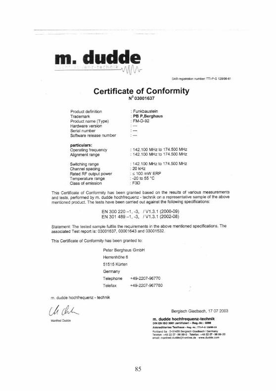
85

Peter Berghaus GmbHVerkehrstechnik - Lichtinnovationen

Peter Berghaus GmbHVerkehrstechnik - Lichtinnovationen

Peter Berghaus GmbHVerkehrstechnik - Lichtinnovationen

Warranty against defects
For the signalling equipment manufactured in our company
During this period we are liable for all material and processing errorswhich are the result of defective manufacturing.
Please send systems or sections of the equipment which need to bereplaced post-free or carriage paid to our works. Only those parts witherrors in the material or in the finishing will be replaced. There can beno demand for cancellation of sale or for lowering the purchase priceunless the damage can not be repaired by us.
The occasion and time required for repairs under the warranty are to begiven after a prior agreement has been made. The warranty expires ifmodifications or repair work are carried out by the customer or a thirdparty without prior permission. Normal wear or damage which are theresult of negligent or improper handling are not included under thewarranty.
the period of warranty lasts for 24 months.


06/2
004Signal Construction • Roadworks Safety Products
Herrenhoehe 6 ·D-51515 Kuerten · Phone +49 2207 9677-0 · Fax +49 2207 9677-80
www.berghaus-verkehrstechnik.de • [email protected]


![mpb-icra2006 [Wazhua.Com]](https://static.fdocuments.in/doc/165x107/577d2ec81a28ab4e1eaff7cc/mpb-icra2006-wazhuacom.jpg)