Bca 2nd sem-u-1.6 digital logic circuits, digital component
32
Digital Logic Circuits, Digital Component and Data Representation Course: BCA-2 nd Sem Subject: Computer Organization And Architecture Unit-1 1
-
Upload
rai-university -
Category
Education
-
view
144 -
download
1
Transcript of Bca 2nd sem-u-1.6 digital logic circuits, digital component
Digital Logic Circuits, Digital Component and Data
Representation
Course: BCA-2nd Sem Subject: Computer Organization
And Architecture Unit-1
1

Basic Logic Gates and Basic Digital Design[1]
• NOT, AND, and OR Gates
• NAND and NOR Gates
• DeMorgan’s Theorem
• Exclusive-OR (XOR) Gate
• Multiple-input Gates

NOT Gate -- Inverter
X Y
01
10
X Y
Y
NOTX Y
Y = ~X
NOT
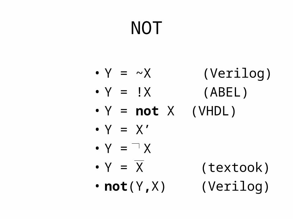
NOT
• Y = ~X (Verilog)• Y = !X (ABEL)• Y = not X (VHDL)• Y = X’• Y = X• Y = X (textook)• not(Y,X) (Verilog)

NOT
X ~X ~~X = X
X ~X ~~X0 1 01 0 1
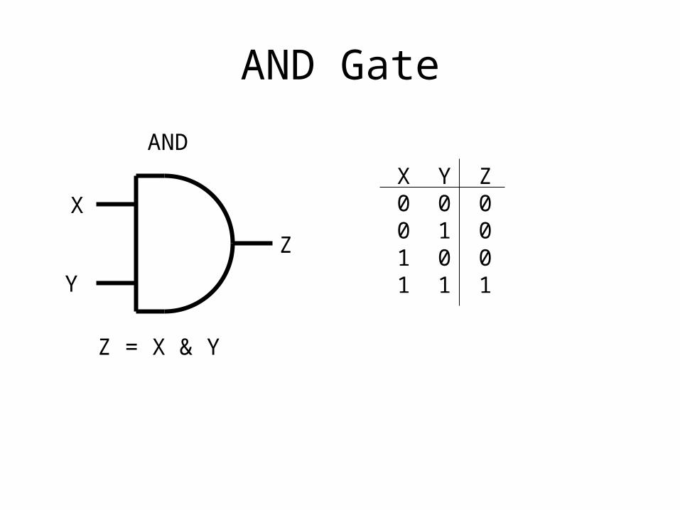
AND Gate
AND
X
Y
Z
Z = X & Y
X Y Z0 0 00 1 01 0 01 1 1
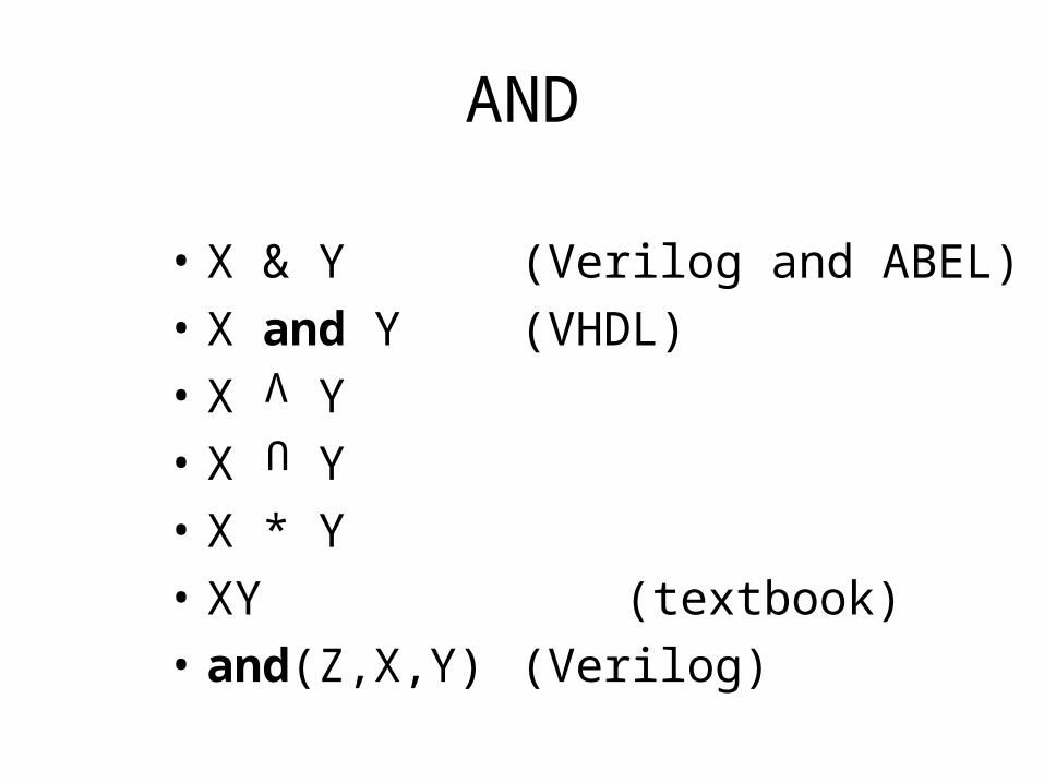
AND
• X & Y (Verilog and ABEL)• X and Y (VHDL)• X Y• X Y• X * Y• XY (textbook)• and(Z,X,Y) (Verilog)
U
V

OR Gate
OR
X
YZ
Z = X | Y
X Y Z0 0 00 1 11 0 11 1 1

OR
• X | Y (Verilog)• X # Y (ABEL)• X or Y (VHDL)• X + Y (textbook)• X V Y• X U Y• or(Z,X,Y) (Verilog)

Basic Logic Gates and Basic Digital Design[1]
• NOT, AND, and OR Gates
• NAND and NOR Gates
• DeMorgan’s Theorem
• Exclusive-OR (XOR) Gate
• Multiple-input Gates

NAND Gate
NAND
X
Y
Z
X Y Z0 0 10 1 11 0 11 1 0
Z = ~(X & Y)nand(Z,X,Y)
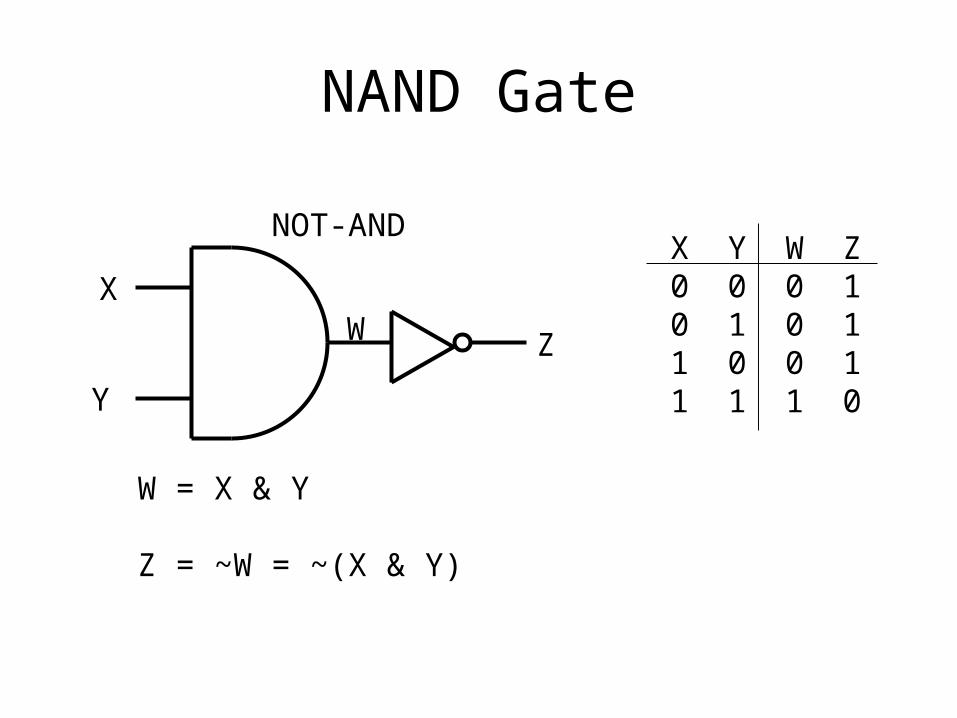
NAND Gate
NOT-AND
X
Y
Z
W = X & Y
Z = ~W = ~(X & Y)
X Y W Z0 0 0 10 1 0 11 0 0 11 1 1 0
W

NOR Gate
NOR
X
YZ
X Y Z0 0 10 1 01 0 01 1 0
Z = ~(X | Y)nor(Z,X,Y)

NOR Gate
NOT-OR
X
Y
W = X | Y
Z = ~W = ~(X | Y)
X Y W Z0 0 0 10 1 1 01 0 1 01 1 1 0
ZW

Basic Logic Gates and Basic Digital Design
• NOT, AND, and OR Gates
• NAND and NOR Gates
• DeMorgan’s Theorem
• Exclusive-OR (XOR) Gate
• Multiple-input Gates
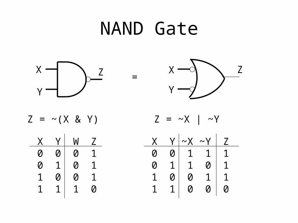
NAND Gate
X
Y
X
Y
Z Z
Z = ~(X & Y) Z = ~X | ~Y
=
X Y W Z0 0 0 10 1 0 11 0 0 11 1 1 0
X Y ~X ~Y Z0 0 1 1 10 1 1 0 11 0 0 1 11 1 0 0 0

De Morgan’s Theorem-1
~(X & Y) = ~X | ~Y
• NOT all variables• Change & to | and | to &• NOT the result
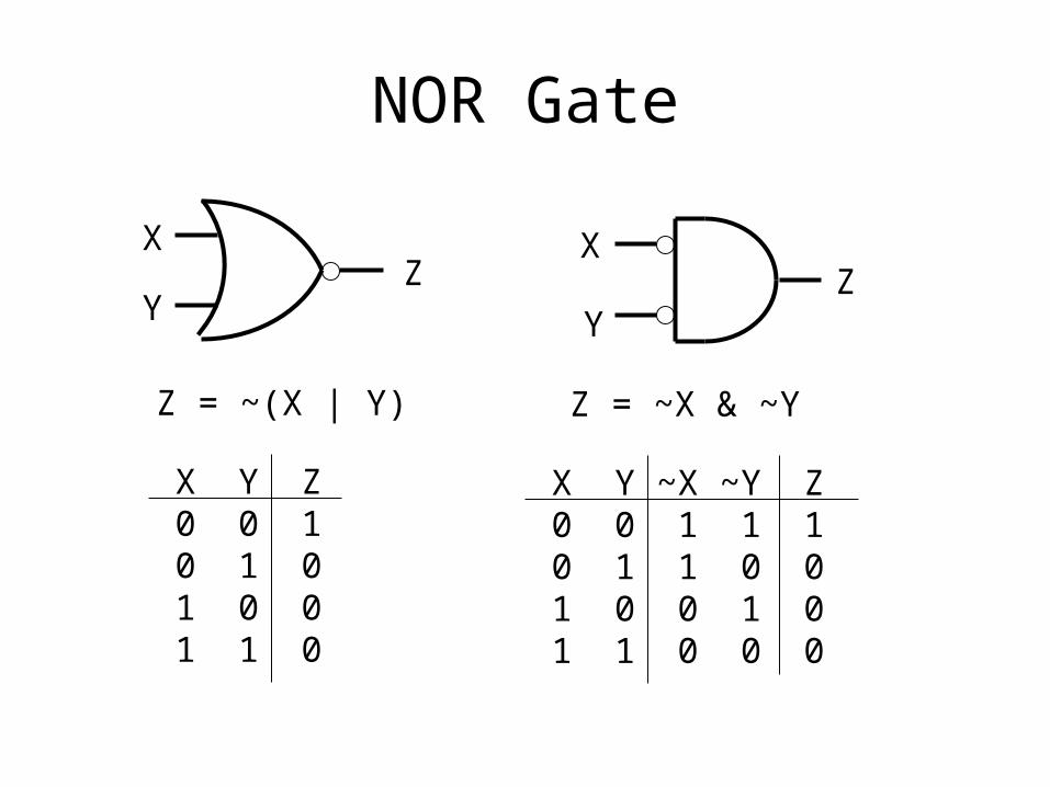
NOR Gate
X
YZ
Z = ~(X | Y)
X Y Z0 0 10 1 01 0 01 1 0
X
YZ
Z = ~X & ~Y
X Y ~X ~Y Z0 0 1 1 10 1 1 0 01 0 0 1 01 1 0 0 0

De Morgan’s Theorem-2
~(X | Y) = ~X & ~Y
• NOT all variables• Change & to | and | to &• NOT the result

De Morgan’s Theorem
• NOT all variables
• Change & to | and | to &
• NOT the result
• --------------------------------------------
• ~X | ~Y = ~(~~X & ~~Y) = ~(X & Y)
• ~(X & Y) = ~~(~X | ~Y) = ~X | ~Y
• ~X & !Y = ~(~~X | ~~Y) = ~(X | Y)
• ~(X | Y) = ~~(~X & ~Y) = ~X & ~Y
Basic Logic Gates and Basic Digital Design[1]
• NOT, AND, and OR Gates
• NAND and NOR Gates
• DeMorgan’s Theorem
• Exclusive-OR (XOR) Gate
• Multiple-input Gates
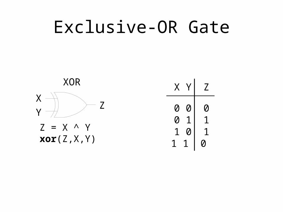
Exclusive-OR Gate
X Y ZXOR
X
YZ 0 0 0
0 1 11 0 11 1 0
Z = X ^ Yxor(Z,X,Y)

XOR
• X ^ Y (Verilog)• X $ Y (ABEL)• X @ Y
• xor(Z,X,Y) (Verilog)
X Y (textbook)
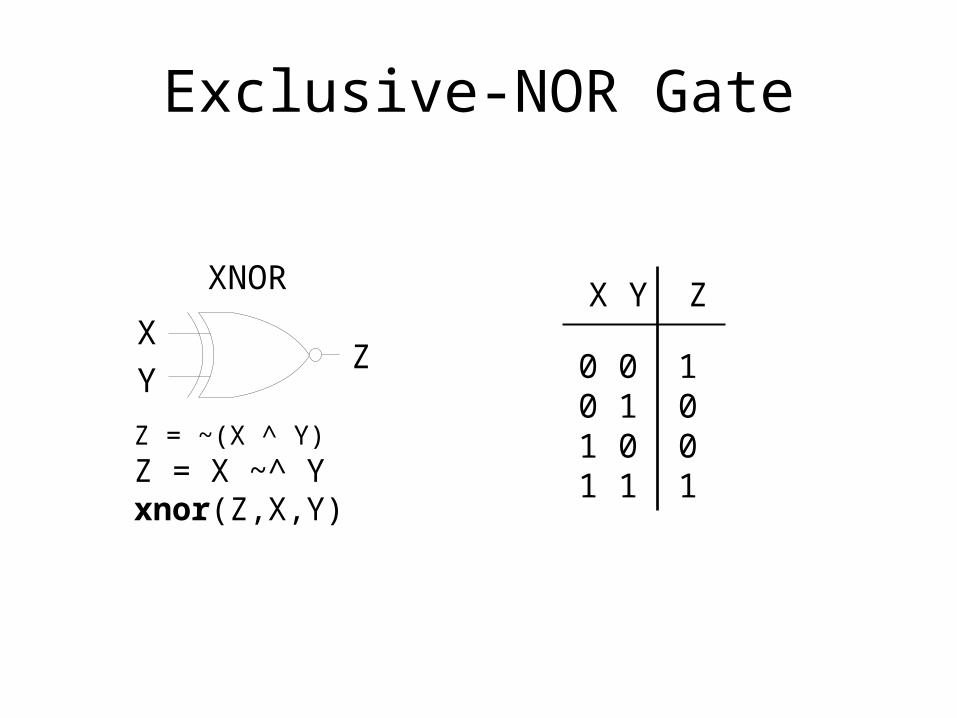
Exclusive-NOR Gate
X Y ZXNOR
X
YZ 0 0 1
0 1 01 0 01 1 1
Z = ~(X ^ Y)Z = X ~^ Yxnor(Z,X,Y)

XNOR
• X ~^ Y (Verilog)• !(X $ Y) (ABEL)• X @ Y
• xnor(Z,X,Y) (Verilog)
X Y

Basic Logic Gates and Basic Digital Design[1]
• NOT, AND, and OR Gates
• NAND and NOR Gates
• DeMorgan’s Theorem
• Exclusive-OR (XOR) Gate
• Multiple-input Gates

Multiple-input Gates[2]
Z 1 2
3 4 Z Z
Z
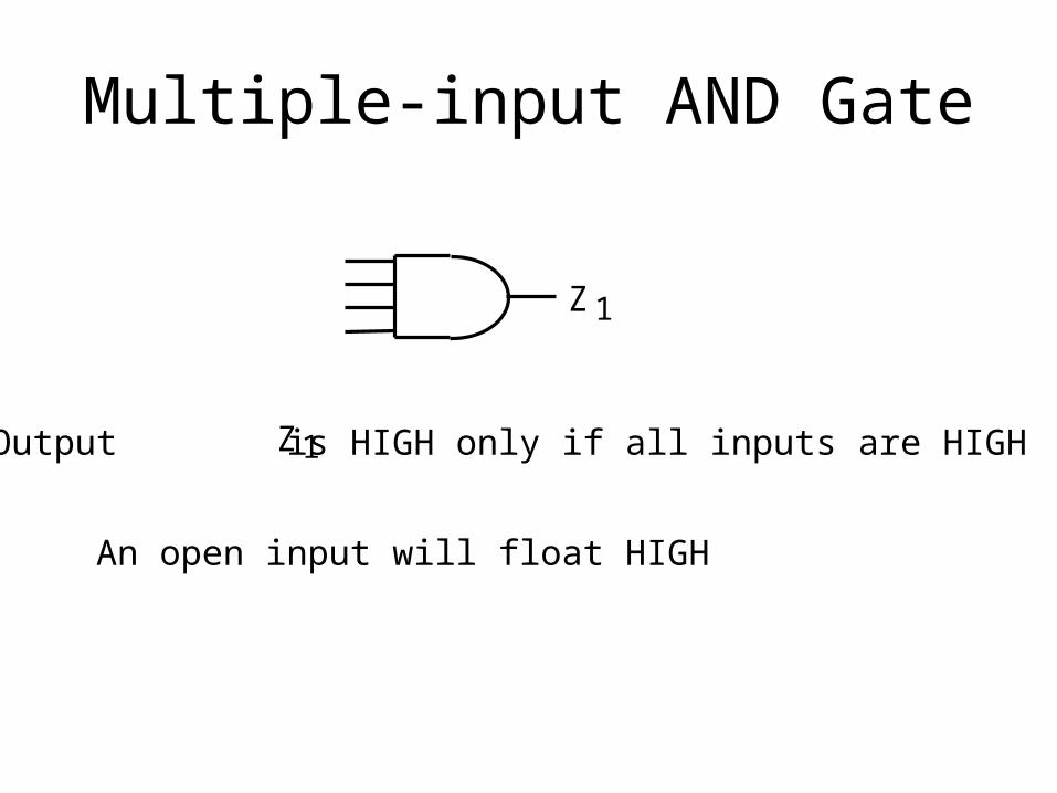
Multiple-input AND Gate
Z 1
Output is HIGH only if all inputs are HIGHZ 1
An open input will float HIGH

Multiple-input OR Gate
Output is LOW only if all inputs are LOWZ 2
2 Z

Multiple-input NAND Gate
Output is LOW only if all inputs are HIGHZ 3
3 Z

Multiple-input NOR Gate
Output is HIGH only if all inputs are LOWZ 4
4 Z
References
1. Computer Organization and Architecture, Designing for performance by William Stallings, Prentice Hall of India.
2. Modern Computer Architecture, by Morris Mano, Prentice Hall of India.
3. Computer Architecture and Organization by John P. Hayes, McGraw Hill Publishing Company.
4. Computer Organization by V. Carl Hamacher, Zvonko G. Vranesic, Safwat G. Zaky, McGraw Hill Publishing Company.