
Digital Transmission Content Protection Specification ... · March 19, 2010 Digital Transmission...
84
Digital Transmission Content Protection Specification Revision 1.7 ED2 2013-06-05 (Informational Version) Page 1 of 84 Digital Transmission Content Protection Specification Volume 1 (Informational Version) Hitachi, Ltd. Intel Corporation Panasonic Corporation Sony Corporation Toshiba Corporation Revision 1.7 ED2 June 5, 2013
Transcript of Digital Transmission Content Protection Specification ... · March 19, 2010 Digital Transmission...
Digital Transmission Content Protection Specification Revision 1.7 ED2
2013-06-05 (Informational Version) Page 1 of 84
DigitalTransmissionContentProtectionSpecification
Volume1(InformationalVersion)
Hitachi, Ltd.
Intel Corporation
Panasonic Corporation
Sony Corporation
Toshiba Corporation
Revision 1.7 ED2
June 5, 2013

Digital Transmission Content Protection Specification Revision 1.7 ED2
2013-06-05 (Informational Version) Page 2 of 84
Preface
NoticeTHIS DOCUMENT IS PROVIDED "AS IS" WITH NO WARRANTIES WHATSOEVER, INCLUDING ANY WARRANTY OF MERCHANTABILITY, NONINFRINGEMENT, FITNESS FOR ANY PARTICULAR PURPOSE, OR ANY WARRANTY OTHERWISE ARISING OUT OF ANY PROPOSAL, SPECIFICATION OR SAMPLE. Hitachi, Intel, Panasonic, Sony, and Toshiba (collectively, the “5C”) disclaim all liability, including liability for infringement of any proprietary rights, relating to use of information in this specification. No license, express or implied, by estoppel or otherwise, to any intellectual property rights is granted herein.
Some portions of this document, identified as "Draft" are in an intermediate draft form and are subject to change without notice. Adopters and other users of this Specification are cautioned these portions are preliminary, and that products based on it may not be interoperable with the final version or subsequent versions thereof.
Copyright © 1997 - 2011 by Hitachi, Ltd., Intel Corporation, Panasonic Corporation, Sony Corporation, and Toshiba Corporation (collectively, the “5C”). Third-party brands and names are the property of their respective owners.
IntellectualPropertyImplementation of this specification requires a license from the Digital Transmission Licensing Administrator.
ContactInformationFeedback on this specification should be addressed to [email protected].
The Digital Transmission Licensing Administrator can be contacted at [email protected].
The URL for the Digital Transmission Licensing Administrator web site is: http://www.dtcp.com.
Printing History:
July 14, 2000 Digital Transmission Content Protection Specification Volume 1 Revision 1.1 February 25, 2002 Digital Transmission Content Protection Specification Volume 1 Revision 1.2a January 07, 2004 Digital Transmission Content Protection Specification Volume 1 Revision 1.3 February 28, 2005 Digital Transmission Content Protection Specification Volume 1 Revision 1.4 June 15, 2007 Digital Transmission Content Protection Specification Volume 1 Revision 1.5 October 1, 2007 Digital Transmission Content Protection Specification Volume 1 Revision 1.51 March 19, 2010 Digital Transmission Content Protection Specification Volume 1 Revision 1.6 September 10, 2010 Digital Transmission Content Protection Specification Volume 1 Revision 1.61
Digital Transmission Content Protection Specification Revision 1.7 ED2
2013-06-05 (Informational Version) Page 3 of 84
TableofContents
PREFACE ........................................................................................................................................................................................ 2
NOTICE .......................................................................................................................................................................................... 2
INTELLECTUAL PROPERTY .............................................................................................................................................................................. 2 CONTACT INFORMATION ............................................................................................................................................................................... 2
CHAPTER 1 INTRODUCTION ........................................................................................................................................................... 9
1.1 PURPOSE AND SCOPE ............................................................................................................................................................................. 9 1.2 OVERVIEW ........................................................................................................................................................................................... 9 1.3 REFERENCES ....................................................................................................................................................................................... 11 1.4 ORGANIZATION OF THIS DOCUMENT ....................................................................................................................................................... 12 1.5 STATE MACHINE NOTATION .................................................................................................................................................................. 13 1.6 NOTATION ......................................................................................................................................................................................... 13 1.7 NUMERICAL VALUES ............................................................................................................................................................................ 13 1.8 BYTE BIT ORDERING ............................................................................................................................................................................. 14 1.9 PACKET FORMAT ................................................................................................................................................................................. 14 1.10 TREATMENT OF PORTIONS OF THE SPECIFICATION MARKED “NOT ESTABLISHED”....................................................................................... 14
CHAPTER 2 ABBREVIATIONS ........................................................................................................................................................ 15
2.1 ALPHABETICAL LIST OF ABBREVIATIONS AND ACRONYMS ............................................................................................................................. 15
CHAPTER 3 THE DIGITAL TRANSMISSION CONTENT PROTECTION SYSTEM .................................................................................... 17
3.1 CONTENT SOURCE DEVICE ..................................................................................................................................................................... 17 3.2 CONTENT SINK DEVICE ......................................................................................................................................................................... 18
CHAPTER 4 FULL AUTHENTICATION ............................................................................................................................................. 20
4.1 INTRODUCTION ................................................................................................................................................................................... 20 4.2 NOTATION ......................................................................................................................................................................................... 20 4.2.1 Defined by the DTLA ........................................................................................................................................................... 20 4.2.1.1 General ........................................................................................................................................................................................... 20 4.2.1.2 For Device X .................................................................................................................................................................................... 20
4.2.2 Notation used during Full Authentication .......................................................................................................................... 21 4.2.3 Device Certificate Formats .................................................................................................................................................. 21 4.2.3.1 Baseline Format .............................................................................................................................................................................. 22 4.2.3.2 Extended Format Fields (NOT ESTABLISHED2 Components of the Device Certificate).................................................................... 23
4.3 MANUFACTURE OF COMPLIANT DEVICES .................................................................................................................................................. 23 4.4 CRYPTOGRAPHIC FUNCTIONS ................................................................................................................................................................. 24 4.4.1 SHA‐1 (Secure Hash Algorithm, revision 1) ......................................................................................................................... 24 4.4.2 Random Number Generator ............................................................................................................................................... 24 4.4.3 Elliptic Curve Cryptography (ECC) ....................................................................................................................................... 24 4.4.3.1 Elliptic Curve Digital Signature Algorithm (EC‐DSA) ........................................................................................................................ 25 4.4.3.2 Elliptic Curve Diffie‐Hellman (EC‐DH) .............................................................................................................................................. 26 4.4.3.3 Implementation of the Elliptic Curve Cryptosystem ....................................................................................................................... 26
4.5 PROTOCOL FLOW ................................................................................................................................................................................ 27 4.5.1 Protocol Flow Overview ...................................................................................................................................................... 27
CHAPTER 5 RESTRICTED AUTHENTICATION .................................................................................................................................. 28
5.1 INTRODUCTION ................................................................................................................................................................................... 28 5.2 NOTATION ......................................................................................................................................................................................... 28 5.2.1 Defined by the DTLA ........................................................................................................................................................... 28 5.2.1.1 General ........................................................................................................................................................................................... 28 5.2.1.2 For Device X .................................................................................................................................................................................... 29

Digital Transmission Content Protection Specification Revision 1.7 ED2
2013-06-05 (Informational Version) Page 4 of 84
5.2.2 Notation used during Restricted Authentication ................................................................................................................ 29 5.2.3 Device Certificate Format ................................................................................................................................................... 30 5.2.4 Random Number Generator ............................................................................................................................................... 30
5.3 PROTOCOL FLOW ................................................................................................................................................................................ 31 5.3.1 Protocol Flow Overview ...................................................................................................................................................... 31
CHAPTER 6 CONTENT CHANNEL MANAGEMENT AND PROTECTION .............................................................................................. 32
6.1 INTRODUCTION ................................................................................................................................................................................... 32 6.2 CONTENT MANAGEMENT KEYS .............................................................................................................................................................. 32 6.2.1 Exchange Key (KX) and Session Exchange Key (KS) .............................................................................................................. 32 6.2.1.1 Exchange Keys (KX) .......................................................................................................................................................................... 32 6.2.1.2 Session Exchange Keys (KS) ............................................................................................................................................................. 32
6.2.2 Content Key (KC) .................................................................................................................................................................. 33 6.2.2.1 KC For M6 ........................................................................................................................................................................................ 33 6.2.2.1.1 M6 Related Key and Constant Sizes ............................................................................................................................................. 33
6.2.2.2 KC for AES‐128 ................................................................................................................................................................................. 34 6.2.2.2.1 AES‐128 Related Key and Constant Sizes ..................................................................................................................................... 34
6.2.3 Alternate Content Key (AKC) ............................................................................................................................................... 35 6.2.3.1 AKC for M6 ....................................................................................................................................................................................... 35 6.2.3.1.1 M6 Related Key and Constant Sizes ............................................................................................................................................. 35
6.2.3.2 AKC for AES‐128 ............................................................................................................................................................................... 36 6.2.3.2.1 AES‐128 Related Key and Constant Sizes ..................................................................................................................................... 36
6.3 PROTOCOL FLOW ................................................................................................................................................................................ 37 6.3.1 Establishing Exchange Key .................................................................................................................................................. 37 6.3.2 Establishing Session Exchange Key ..................................................................................................................................... 37 6.3.3 Establishing Content Keys ................................................................................................................................................... 38 6.3.4 Odd/Even Bit ....................................................................................................................................................................... 39
6.4 COPY CONTROL INFORMATION (CCI) ...................................................................................................................................................... 39 6.4.1 Embedded CCI ..................................................................................................................................................................... 39 6.4.1.1 DTCP_Descriptor for MPEG‐TS ........................................................................................................................................................ 39 6.4.1.2 Content Management Information (CMI) ....................................................................................................................................... 40
6.4.2 Encryption Mode Indicator (EMI) ....................................................................................................................................... 40 6.4.3 Relationship between Embedded CCI and EMI ................................................................................................................... 41 6.4.4 Treatment of EMI/Embedded CCI for Audiovisual Device Functions .................................................................................. 42 6.4.4.1 Format‐cognizant source function .................................................................................................................................................. 42 6.4.4.2 Format‐non‐cognizant source function........................................................................................................................................... 42 6.4.4.3 Format‐cognizant recording function ............................................................................................................................................. 43 6.4.4.4 Format‐cognizant sink function ...................................................................................................................................................... 43 6.4.4.5 Format‐non‐cognizant recording function ...................................................................................................................................... 43 6.4.4.6 Format‐non‐cognizant sink function ............................................................................................................................................... 43
6.4.5 Treatment of EMI/Embedded CCI Audio Device Functions ................................................................................................. 44 6.4.5.1 Embedded CCI for audio transmission ............................................................................................................................................ 44 6.4.5.2 Relationship between Embedded CCI and EMI ............................................................................................................................... 44 6.4.5.3 Audio‐Format‐cognizant source function ....................................................................................................................................... 44 6.4.5.4 Audio‐Format‐non‐cognizant source function ................................................................................................................................ 44 6.4.5.5 Audio‐Format‐cognizant recording function ................................................................................................................................... 45 6.4.5.6 Audio‐Format‐cognizant sink function ............................................................................................................................................ 45 6.4.5.7 Audio‐Format‐non‐cognizant recording function ........................................................................................................................... 45 6.4.5.8 Audio‐Format‐non‐cognizant sink function .................................................................................................................................... 45
6.5 COMMON DEVICE CATEGORIES .............................................................................................................................................................. 45 6.6 CONTENT CHANNEL CIPHERS ................................................................................................................................................................. 46 6.6.1 Baseline Cipher ................................................................................................................................................................... 46 6.6.2 Optional Cipher (NOT ESTABLISHED2) ................................................................................................................................. 46 6.6.2.1 AES‐128 Cipher................................................................................................................................................................................ 46
6.6.3 Content Encryption Formats ............................................................................................................................................... 47 6.6.3.1 For M6 ............................................................................................................................................................................................. 47

Digital Transmission Content Protection Specification Revision 1.7 ED2
2013-06-05 (Informational Version) Page 5 of 84
6.6.3.2 For AES‐128 ..................................................................................................................................................................................... 47 6.7 ADDITIONAL FUNCTIONS ....................................................................................................................................................................... 48 6.7.1 Move Function .................................................................................................................................................................... 48 6.7.2 Retention Function ............................................................................................................................................................. 48
CHAPTER 7 SYSTEM RENEWABILITY ............................................................................................................................................. 49
7.1 INTRODUCTION ................................................................................................................................................................................... 49 7.1.1 SRM Message Components and Layout ............................................................................................................................. 49 7.1.1.1 Certificate Revocation List (CRL) ..................................................................................................................................................... 50 7.1.1.2 DTLA EC‐DSA Signature ................................................................................................................................................................... 50
7.1.2 SRM Scalability ................................................................................................................................................................... 51 7.2 UPDATING SRMS ................................................................................................................................................................................ 51 7.2.1 Device‐to‐Device Update and State Machines ................................................................................................................... 52 7.2.1.1 Updating a Device’s SRM from Another Compliant Device ............................................................................................................ 52
CHAPTER 8 AV/C DIGITAL INTERFACE COMMAND SET EXTENSIONS ............................................................................................. 53
8.1 INTRODUCTION ................................................................................................................................................................................... 53 8.2 SECURITY COMMAND ......................................................................................................................................................................... 53 8.3 AKE COMMAND .................................................................................................................................................................................. 53 8.3.1 AKE control command ........................................................................................................................................................ 54 8.3.2 AKE status command .......................................................................................................................................................... 56 8.3.3 AKE_ID dependent field (AKE_ID = 0) ................................................................................................................................. 57
8.4 BUS RESET BEHAVIOR ........................................................................................................................................................................... 59 8.5 ACTION WHEN UNAUTHORIZED DEVICE IS DETECTED DURING AUTHENTICATION .............................................................................................. 59 8.6 AUTHENTICATION AV/C COMMAND FLOWS ............................................................................................................................................. 60 8.6.1 Figure Notation ................................................................................................................................................................... 60 8.6.2 Full Authentication Command Flow ................................................................................................................................... 60 8.6.3 Enhanced Restricted / Restricted Authentication Command Flow ..................................................................................... 61
APPENDIX A ADDITIONAL RULES FOR AUDIO APPLICATIONS ........................................................................................................ 62
A.1 AM824 AUDIO .................................................................................................................................................................................. 62 A.1.1 Type 1: IEC 60958 Conformant Audio ...................................................................................................................................... 62 A.1.1.1 Definition ................................................................................................................................................................................................ 62 A.1.1.2 Relationship between ASE‐CCI and Embedded CCI ................................................................................................................................ 62 A.1.1.3 Usage of Mode A (EMI=11) ..................................................................................................................................................................... 62
A.1.2 Type 2: DVD‐Audio ............................................................................................................................................................... 63 A.1.2.1 Definition ................................................................................................................................................................................................ 63 A.1.2.2 Relationship between ASE‐CCI and Embedded CCI ................................................................................................................................ 63 A.1.2.3 Usage of Mode A (EMI=11) ..................................................................................................................................................................... 63 A.1.2.4 Additional rules for recording ................................................................................................................................................................. 63
A.1.3 Type 3: Super Audio CD ........................................................................................................................................................... 64 A.1.3.1 Definition ................................................................................................................................................................................................ 64 A.1.3.2 Relationship between ASE‐CCI and Embedded CCI ................................................................................................................................ 64 A.1.3.3 Usage of Mode A (EMI=11) ..................................................................................................................................................................... 64
A.2 MPEG AUDIO .................................................................................................................................................................................... 64
APPENDIX B DTCP_DESCRIPTOR FOR MPEG TRANSPORT STREAMS .............................................................................................. 65
B.1 DTCP_DESCRIPTOR ............................................................................................................................................................................. 65 B.2 DTCP_DESCRIPTOR SYNTAX .................................................................................................................................................................. 65 B.2.1 private_data_byte Definitions: ................................................................................................................................................ 66
B.3 RULES FOR THE USAGE OF THE DTCP_DESCRIPTOR .................................................................................................................................... 68 B.3.1 Transmission of a partial MPEG TS .......................................................................................................................................... 68 B.3.2 Transmission of a full MPEG TS ............................................................................................................................................... 68 B.3.3 Treatment of the DTCP_descriptor by the sink device ............................................................................................................. 68
APPENDIX C LIMITATION OF THE NUMBER OF SINK DEVICES RECEIVING A CONTENT STREAM ...................................................... 69
Digital Transmission Content Protection Specification Revision 1.7 ED2
2013-06-05 (Informational Version) Page 6 of 84
C.1 LIMITATION MECHANISM IN SOURCE DEVICE ............................................................................................................................................ 69 C.2 LIMITATION MECHANISM IN DTCP BUS BRIDGE DEVICE ............................................................................................................................. 71 C.2.1 DTCP Bus Bridge Device Source Function ................................................................................................................................. 71 C.2.2 DTCP Bus Bridge Device Sink Function ..................................................................................................................................... 71 C.2.3 Extra Key handling ................................................................................................................................................................... 72 C.2.4 Implementation of DTCP bus bridge ........................................................................................................................................ 72 C.2.4.1 Implementation of DTCP bus bridge device without Key Counter ......................................................................................................... 73 C.2.4.2 Implementation of DTCP bus bridge device with Key Counter ............................................................................................................... 73
C.2.5 Additional device certificate in a DTCP bus bridge device ....................................................................................................... 74 C.2.6 Treatment of additional function in a DTCP bus bridge device ................................................................................................ 74
APPENDIX D DTCP ASYNCHRONOUS CONNECTION ...................................................................................................................... 75
D.1 PURPOSE AND SCOPE ........................................................................................................................................................................... 75 D.2 TRANSMISSION OF PROTECTED FRAME .................................................................................................................................................... 75 D.2.1 Overview .................................................................................................................................................................................. 75 D.2.2 Protected Content Packet ........................................................................................................................................................ 75 D.2.3 Construction of Protected Frame ............................................................................................................................................. 77 D.2.4 NC Update Process ................................................................................................................................................................... 77 D.2.5 Duration of Exchange Keys ...................................................................................................................................................... 77 D.2.6 Frame Transfer type ................................................................................................................................................................ 78 D.2.6.1 File‐type Transfer ................................................................................................................................................................................... 78 D.2.6.2 Stream‐type Transfer ............................................................................................................................................................................. 78
D.3 EMBEDDED CCI .................................................................................................................................................................................. 78 D.4 AKE COMMAND EXTENSIONS ................................................................................................................................................................ 78 D.4.1 Status Field .............................................................................................................................................................................. 78
APPENDIX E CONTENT MANAGEMENT INFORMATION (CMI) ....................................................................................................... 79
E.1 GENERAL ........................................................................................................................................................................................... 79 E.1.1 Purpose and Scope ................................................................................................................................................................... 79 E.1.2 General Rules for Source Devices ............................................................................................................................................. 80 E.1.3 General Rules for Sink Devices ................................................................................................................................................. 80
E.2 CMI FIELD ......................................................................................................................................................................................... 80 E.3 CMI DESCRIPTOR DESCRIPTIONS ............................................................................................................................................................ 81 E.3.1 CMI Descriptor General Format ............................................................................................................................................... 81 E.3.2 CMI Descriptor 0 ...................................................................................................................................................................... 82 E.3.2.1 CMI Descriptor 0 Format ......................................................................................................................................................................... 82 E.3.2.2 Rules for Source Devices ......................................................................................................................................................................... 82 E.3.2.3 Rules for Sink Devices ............................................................................................................................................................................. 82
E.3.3 CMI Descriptor 1 ...................................................................................................................................................................... 83 E.3.3.1 CMI Descriptor 1 Format ......................................................................................................................................................................... 83 E.3.3.2 Rules for Source Devices ......................................................................................................................................................................... 84 E.3.3.3 Rules for Sink Devices ............................................................................................................................................................................. 84
E.3.4 CMI Descriptor 2 ...................................................................................................................................................................... 84 E.3.4.1 CMI Descriptor 2 Format ......................................................................................................................................................................... 84 E.3.4.2 Rules for Sources Devices ....................................................................................................................................................................... 84 E.3.4.3 Rules for Sink Devices ............................................................................................................................................................................. 84
Digital Transmission Content Protection Specification Revision 1.7 ED2
2013-06-05 (Informational Version) Page 7 of 84
Figures
FIGURE 1 CONTENT PROTECTION OVERVIEW ...................................................................................................................................................... 10 FIGURE 2 STATE MACHINE EXAMPLE ............................................................................................................................................................... 13 FIGURE 3 8 BIT DIAGRAMS .............................................................................................................................................................................. 14 FIGURE 4 PACKET FORMAT ............................................................................................................................................................................. 14 FIGURE 5 CONTENT SOURCE DEVICE STATE MACHINE .......................................................................................................................................... 17 FIGURE 6 CONTENT SINK DEVICE STATE MACHINE .............................................................................................................................................. 18 FIGURE 7 BASELINE DEVICE CERTIFICATE FORMAT ............................................................................................................................................... 22 FIGURE 8 EXTENDED DEVICE CERTIFICATE FIELDS ................................................................................................................................................ 23 FIGURE 9 FULL AUTHENTICATION PROTOCOL FLOW OVERVIEW ............................................................................................................................. 27 FIGURE 10 RESTRICTED AUTHENTICATION DEVICE CERTIFICATE FORMAT ................................................................................................................. 30 FIGURE 11 KEY SELECTION VECTOR .................................................................................................................................................................. 30 FIGURE 12 RESTRICTED AUTHENTICATION PROTOCOL FLOW OVERVIEW .................................................................................................................. 31 FIGURE 13 CONTENT CHANNEL ESTABLISHMENT AND MANAGEMENT PROTOCOL FLOW OVERVIEW ............................................................................. 38 FIGURE 14 ODD/EVEN BIT LOCATION IN THE PACKET HEADER .............................................................................................................................. 39 FIGURE 15 EMI LOCATION ............................................................................................................................................................................. 40 FIGURE 16 STRUCTURE OF THE FIRST GENERATION SYSTEM RENEWABILITY MESSAGE ................................................................................................ 49 FIGURE 17 FORMAT OF THE CRL ENTRY TYPE BLOCK ........................................................................................................................................... 50 FIGURE 18 EXAMPLE CRL............................................................................................................................................................................... 50 FIGURE 19 SRM EXTENSIBILITY ....................................................................................................................................................................... 51 FIGURE 20 SECURITY COMMAND ..................................................................................................................................................................... 53 FIGURE 21 SECURITY COMMAND CATEGORY FIELD ............................................................................................................................................... 53 FIGURE 22 AKE CONTROL COMMAND .............................................................................................................................................................. 54 FIGURE 23 AKE CONTROL COMMAND STATUS FIELD........................................................................................................................................... 55 FIGURE 24 AKE CONTROL COMMAND STATUS FIELD TEST VALUES ........................................................................................................................ 55 FIGURE 25 AKE STATUS COMMAND ................................................................................................................................................................ 56 FIGURE 26 AKE STATUS COMMAND STATUS FIELD ............................................................................................................................................. 56 FIGURE 27 AKE STATUS COMMAND STATUS FIELD TEST VALUES ........................................................................................................................... 56 FIGURE 28 AKE_ID DEPENDENT FIELD .............................................................................................................................................................. 57 FIGURE 29 FULL AUTHENTICATION COMMAND FLOW .......................................................................................................................................... 60 FIGURE 30 ENHANCED RESTRICTED/RESTRICTED AUTHENTICATION COMMAND FLOW ............................................................................................... 61 FIGURE 31 SINK COUNTER ALGORITHM (INFORMATIVE) ....................................................................................................................................... 70 FIGURE 32 DTCP BUS BRIDGE STATE MACHINE WITHOUT KEY COUNTER (INFORMATIVE) ........................................................................................... 73 FIGURE 33 DTCP BUS BRIDGE STATE MACHINE WITH KEY COUNTER (INFORMATIVE) ................................................................................................. 74 FIGURE 34 STRUCTURE OF PROTECTED CONTENT PACKET ..................................................................................................................................... 75 FIGURE 35 STRUCTURE OF DATA PACKET .......................................................................................................................................................... 76 FIGURE 36 GENERIC CONSTRUCTION OF PROTECTED CONTENT PACKET IN THE PROTECTED FRAME .............................................................................. 77
Tables
TABLE 1 LENGTH OF KEYS AND VARIABLES GENERATED BY THE DEVICE (FULL AUTHENTICATION) .................................................................................... 21 TABLE 2 LENGTH OF KEYS AND CONSTANTS CREATED BY DTLA (RESTRICTED AUTHENTICATION) .................................................................................. 29 TABLE 3 LENGTH OF KEYS AND VARIABLES GENERATED BY THE DEVICE (RESTRICTED AUTHENTICATION) .......................................................................... 29 TABLE 4 SIZE OF M6 RELATED CONTENT MANAGEMENT KEYS AND CONSTANTS ....................................................................................................... 33 TABLE 5 LENGTH OF KEYS AND CONSTANTS (CONTENT CHANNEL MANAGEMENT) ..................................................................................................... 34 TABLE 6 SIZE OF M6 RELATED CONTENT MANAGEMENT KEYS AND CONSTANTS ....................................................................................................... 35 TABLE 7 LENGTH OF KEYS AND CONSTANTS (CONTENT CHANNEL MANAGEMENT) ..................................................................................................... 36 TABLE 8 EMI ENCODING ................................................................................................................................................................................ 41 TABLE 9 RELATIONSHIP BETWEEN EMI AND EMBEDDED CCI ................................................................................................................................. 41 TABLE 10 FORMAT‐COGNIZANT SOURCE FUNCTION CCI HANDLING ....................................................................................................................... 42 TABLE 11 FORMAT‐NON‐COGNIZANT SOURCE FUNCTION CCI HANDLING ............................................................................................................... 42

Digital Transmission Content Protection Specification Revision 1.7 ED2
2013-06-05 (Informational Version) Page 8 of 84
TABLE 12 FORMAT‐COGNIZANT RECORDING FUNCTION CCI HANDLING ................................................................................................................... 43 TABLE 13 FORMAT‐COGNIZANT SINK FUNCTION CCI HANDLING ............................................................................................................................. 43 TABLE 14 FORMAT‐NON‐COGNIZANT RECORDING FUNCTION CCI HANDLING ............................................................................................................ 43 TABLE 15 EMBEDDED CCI VALUES ................................................................................................................................................................... 44 TABLE 16 AUDIO‐FORMAT‐CONGNIZANT SOURCE FUNCTION CCI HANDLING ........................................................................................................... 44 TABLE 17 AUDIO‐FORMAT‐COGNIZANT RECORDING FUNCTION CCI HANDLING ......................................................................................................... 45 TABLE 18 AUDIO‐FORMAT‐COGNIZANT SINK FUNCTION CCI HANDLING ................................................................................................................... 45 TABLE 19 M6 CONTENT ENCRYPTION FORMATS ................................................................................................................................................. 47 TABLE 20 AES‐128 CONTENT ENCRYPTION FORMATS ......................................................................................................................................... 47 TABLE 21 DV FORMAT MOVE FUNCTION MODES ............................................................................................................................................... 48 TABLE 22 DV FORMAT RETENTION FUNCTION MODES ........................................................................................................................................ 48 TABLE 23 AKE SUBFUNCTIONS ........................................................................................................................................................................ 57 TABLE 24 AKE_PROCEDURE VALUES ................................................................................................................................................................ 58 TABLE 25 AUTHENTICATION SELECTION ............................................................................................................................................................. 58 TABLE 26 EXCHANGE_KEY VALUES ................................................................................................................................................................... 59 TABLE 27 RELATIONSHIPS BETWEEN SCMS STATE AND EMBEDDED CCI .................................................................................................................. 62 TABLE 28 DVD AUDIO, RELATIONSHIP BETWEEN ASE‐CCI AND EMBEDDED CCI ...................................................................................................... 63 TABLE 29 SUPER AUDIO CD, RELATIONSHIP BETWEEN ASE‐CCI AND EMBEDDED CCI ............................................................................................... 64 TABLE 30 DTCP_DESCRIPTOR SYNTAX .............................................................................................................................................................. 65 TABLE 31 SYNTAX OF PRIVATE_DATA_BYTE FOR DTCP_DESCRIPTOR ...................................................................................................................... 65 TABLE 32 MOVE FUNCTION MODES ................................................................................................................................................................. 66 TABLE 33 RETENTION FUNCTION MODES .......................................................................................................................................................... 66 TABLE 34 RETENTION STATES .......................................................................................................................................................................... 66 TABLE 35 EPN ............................................................................................................................................................................................. 66 TABLE 36 DTCP_CCI .................................................................................................................................................................................... 67 TABLE 37 DOT ............................................................................................................................................................................................ 67 TABLE 38 AST ............................................................................................................................................................................................. 67 TABLE 39 IMAGE_CONSTRAINT_TOKEN ............................................................................................................................................................ 67 TABLE 40 APS ............................................................................................................................................................................................. 67 TABLE 41 CONTENT TYPE ............................................................................................................................................................................... 76 TABLE 42 C_T FIELD ..................................................................................................................................................................................... 82

Digital Transmission Content Protection Specification Revision 1.7 ED2
2013-06-05 (Informational Version) Page 9 of 84
Chapter1 Introduction
1.1 PurposeandScopeThe Digital Transmission Content Protection Specification defines a cryptographic protocol for protecting audio/video entertainment content from unauthorized copying, intercepting, and tampering as it traverses digital transmission mechanisms such as a high-performance serial bus that conforms to the IEEE 1394-1995 standard. Only legitimate entertainment content delivered to a source device via another approved copy protection system (such as the DVD Content Scrambling System) will be protected by this copy protection system.
The use of this specification and access to the intellectual property and cryptographic materials required to implement it will be the subject of a license. The Digital Transmission Licensing Administrator (DTLA) is responsible for establishing and administering the content protection system described in this specification.
While DTCP has been designed for use by devices attached to serial buses as defined by the IEEE 1394-1995 standard, the developers anticipate that it will be appropriate for use with future extensions to this standard, other transmission systems, and other types of content as authorized by the DTLA.
1.2 OverviewThis specification addresses four layers of copy protection:
Copy control information (CCI)
Content owners need a way to specify how their content can be used (“copy-one-generation,” “copy-never,” etc.). This content protection system is capable of securely communicating copy control information (CCI) between devices in two ways:
The Encryption Mode Indicator (EMI) provides easily accessible yet secure transmission of CCI via the most significant two bits of the sy field of the isochronous packet header.
CCI is embedded in the content stream (e.g. MPEG). This form of CCI is processed only by devices which recognize the specific content format.
Device authentication and key exchange (AKE)
Before sharing valuable information, a connected device must first verify that another connected device is authentic. To balance the protection requirements of the content industries with the real-world requirements of PC and consumer electronics (CE) device users, this specification includes two authentication levels, Full and Restricted.
Full Authentication can be used with all content protected by the system.
Restricted Authentication enables the protection of “copy-one-generation” and “no-more-copies” content only. Copying devices such as digital VCRs employ this kind of authentication.
Content encryption
Devices include a channel cipher subsystem that encrypts and decrypts copyrighted content. To ensure interoperability, all devices must support the specific cipher specified as the baseline cipher. The subsystem can also support additional ciphers, whose use is negotiated during authentication.
Digital Transmission Content Protection Specification Revision 1.7 ED2
2013-06-05 (Informational Version) Page 10 of 84
System renewability
Devices that support Full Authentication can receive and process system renewability messages (SRMs) created by the DTLA and distributed with content and new devices. System renewability ensures long-term integrity of the system through the revocation of compromised devices.
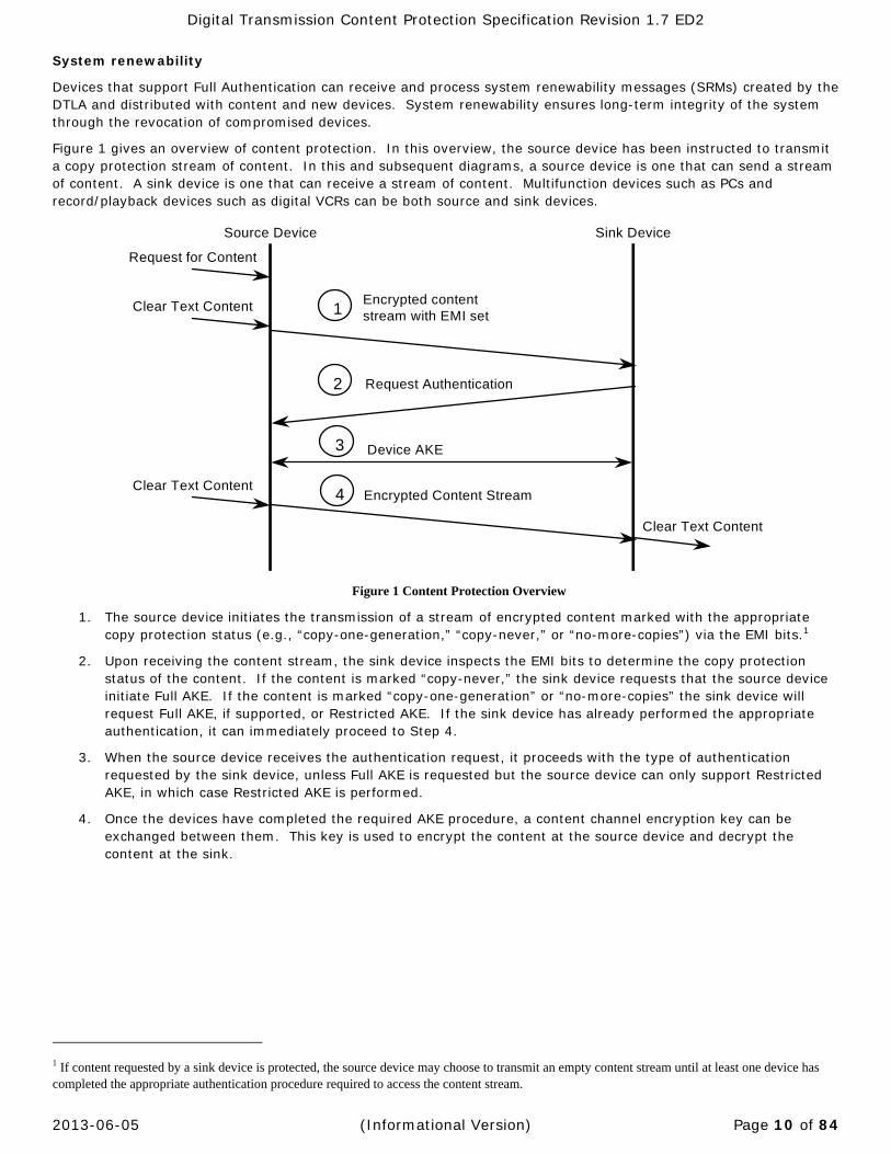
Figure 1 gives an overview of content protection. In this overview, the source device has been instructed to transmit a copy protection stream of content. In this and subsequent diagrams, a source device is one that can send a stream of content. A sink device is one that can receive a stream of content. Multifunction devices such as PCs and record/playback devices such as digital VCRs can be both source and sink devices.
Figure 1 Content Protection Overview
1. The source device initiates the transmission of a stream of encrypted content marked with the appropriate copy protection status (e.g., “copy-one-generation,” “copy-never,” or “no-more-copies”) via the EMI bits.1
2. Upon receiving the content stream, the sink device inspects the EMI bits to determine the copy protection status of the content. If the content is marked “copy-never,” the sink device requests that the source device initiate Full AKE. If the content is marked “copy-one-generation” or “no-more-copies” the sink device will request Full AKE, if supported, or Restricted AKE. If the sink device has already performed the appropriate authentication, it can immediately proceed to Step 4.
3. When the source device receives the authentication request, it proceeds with the type of authentication requested by the sink device, unless Full AKE is requested but the source device can only support Restricted AKE, in which case Restricted AKE is performed.
4. Once the devices have completed the required AKE procedure, a content channel encryption key can be exchanged between them. This key is used to encrypt the content at the source device and decrypt the content at the sink.
1 If content requested by a sink device is protected, the source device may choose to transmit an empty content stream until at least one device has completed the appropriate authentication procedure required to access the content stream.
Encrypted content stream with EMI set
Request Authentication
Device AKE
Encrypted Content Stream
1
3
4
2
Source Device Sink Device
Request for Content
Clear Text Content
Clear Text Content
Clear Text Content
Digital Transmission Content Protection Specification Revision 1.7 ED2
2013-06-05 (Informational Version) Page 11 of 84
1.3 ReferencesThis specification shall be used in conjunction with the following publications. When the publications are superseded by an approved revision, the revision shall apply.
1394 Trade Association, Specification for AV/C Digital Interface Command Set General Specification Version 4.1 December 11, 2001.
1394 Trade Association Document 2001003, Audio and Music Data Transmission Protocol 2.0, August 21, 2001.
1394 Trade Association Document 2001009, AV/C Compatible Asynchronous Serial Bus Connections 2.1, July 23, 2001
1394 Trade Association Document 1999037, AV/C Command for Management of Enhanced Asynchronous Serial Bus Connections 1.0, October 24, 2000
1394 Trade Association Document 2006020, BT.601 Transport Over IEEE-1394 1.1a, October 02, 2006
Advanced Encryption Standard (AES) FIPS 197 November 26, 2001
ATSC, A/70 Conditional Access System for Terrestrial Broadcast
Cable Television Laboratories, HDND Interface Specification Version 2.2
Digital Transmission Licensing Administrator, DIGITAL TRANSMISSION PROTECTION LICENSE AGREEMENT, Development and Evaluation License
ETSI EN 300 468, DVB, Specification for Service Information (SI) in DVB Systems
IEC 61834 Helical-scan digital video cassette recording system using 6.35 mm magnetic tape for consumer use (525-60, 625-50, 1125-60 and 1250-50 systems)
IEC/ISO 13818-1:2000(E) Information Technology – Generic coding of moving pictures and associated audio information Systems, Second edition, 2000-12-01
IEEE 1363-2000, IEEE Standard Specification for Public-Key Cryptography
IEEE 1394-1995, Standard for a High Performance Serial Bus
ISO/IEC 61883, Digital Interface for Consumer Audio/Video Equipment
ITU-R Rec. BO.1516 System B Transport Stream
National Institute of Standards and Technology (NIST), Secure Hash Standard (SHS), FIPS Publication 180-2 August 1, 2002
NIST Special Publication 800-38A 2001 Edition (SP800-38A), Recommendation for Block Cipher Modes of Operation
Toshiba Corporation, Scheme for Computing Montgomery Division and Montgomery Inverse Realizing Fast Implementation, Japanese patent application number PH10-269060

Digital Transmission Content Protection Specification Revision 1.7 ED2
2013-06-05 (Informational Version) Page 12 of 84
1.4 OrganizationofthisDocumentThis specification is organized as follows:
Chapter 1 provides an overview of digital transmission content protection.
Chapter 2 lists the abbreviations used throughout this document.
Chapter 3 describes the operation of the overall Digital Transmission Content Protection System as a state machine.
Chapter 4 addresses the particulars of the Full Authentication level of device authentication and key exchange.
Chapter 5 addresses the particulars of the Restricted Authentication level of device authentication and key exchange.
Chapter 6 describes the details of content channel establishment after Full or Restricted Authentication takes place.
Chapter 7 describes the System Renewability capabilities.
Chapter 8 covers AV/C command extensions.
Appendix A Additional Rules for Audio Application Types
Appendix B DTCP_Descriptor for MPEG Transport Streams
Appendix C Limitation of the Number of Sink Devices Receiving a Content Stream
Appendix D DTCP Asynchronous Connection
Appendix E Content Management Information
Volume 1 Supplement A Mapping DTCP to USB
Volume 1 Supplement B Mapping DTCP to MOST
Volume 1 Supplement C Mapping DTCP to Bluetooth
Volume 1 Supplement D DTCP Use of IEEE1394 Similar Transports
Volume 1 Supplement E Mappping DTCP to IP
Volume 1 Supplement F DTCP 1394 Additional Localization
Volume 1 Supplement G Mapping DTCP to WirelessHD

Digital Transmission Content Protection Specification Revision 1.7 ED2
2013-06-05 (Informational Version) Page 13 of 84
1.5 StateMachineNotationState machines are employed throughout this document to show various states of operation. These state machines use the style shown in Figure 2.
Figure 2 State Machine Example
State machines make three assumptions:
Time elapses only within discrete states.
State transitions are instantaneous, so the only actions taken during a transition are setting flags and variables and sending signals.
Every time a state is entered, the actions of that state are started. A transaction that points back to the same state will restart the actions from the beginning.
1.6 NotationThe following notation will be used:
[X]msb_z The most significant z bits of X
[X]lsb_z The least significant z bits of X
SX-1[M] Sign M using EC-DSA with private key X-1 (See Chapter 4)
VX1[M] Verify signature of M using EC-DSA with public key X1 (See Chapter 4)
X || Y Ordered Concatenation of X with Y.
X Y Bit-wise Exclusive-OR (XOR) of two strings X and Y.
1 MB = 1024 x 1024 Bytes
1.7 NumericalValuesThree difference representations of number are used in this specification. Decimal numbers are represented without any special notation. Binary number are represented as a string of binary (0, 1) digits followed by a subscript 2 (e.g., 10102). Hexadecimal numbers are represented as a string of hexadecimal digits (0..9,A..F) followed by a subscript 16 (e.g., 3C216).
condition for transition from S0 to S1
S1: State 1actions started on entry to S1
action taken on this transition
S0: State 0actions started on entry to S0
condition for transition from S1 to S0
action taken on this transition
Digital Transmission Content Protection Specification Revision 1.7 ED2
2013-06-05 (Informational Version) Page 14 of 84
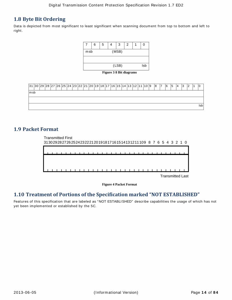
1.8 ByteBitOrderingData is depicted from most significant to least significant when scanning document from top to bottom and left to right.
7 6 5 4 3 2 1 0
msb (MSB)
(LSB) lsb
Figure 3 8 Bit diagrams
31 30 29 28 27 26 25 24 23 22 21 20 19 18 17 16 15 14 13 12 11 10 9 8 7 6 5 4 3 2 1 0
msb
lsb
1.9 PacketFormat
Figure 4 Packet Format
1.10 TreatmentofPortionsoftheSpecificationmarked“NOTESTABLISHED”Features of this specification that are labeled as “NOT ESTABLISHED” describe capabilities the usage of which has not yet been implemented or established by the 5C.
313029282726252423222120191817161514131211109 1 0235 4678Transmitted First
Transmitted Last
Digital Transmission Content Protection Specification Revision 1.7 ED2
2013-06-05 (Informational Version) Page 15 of 84
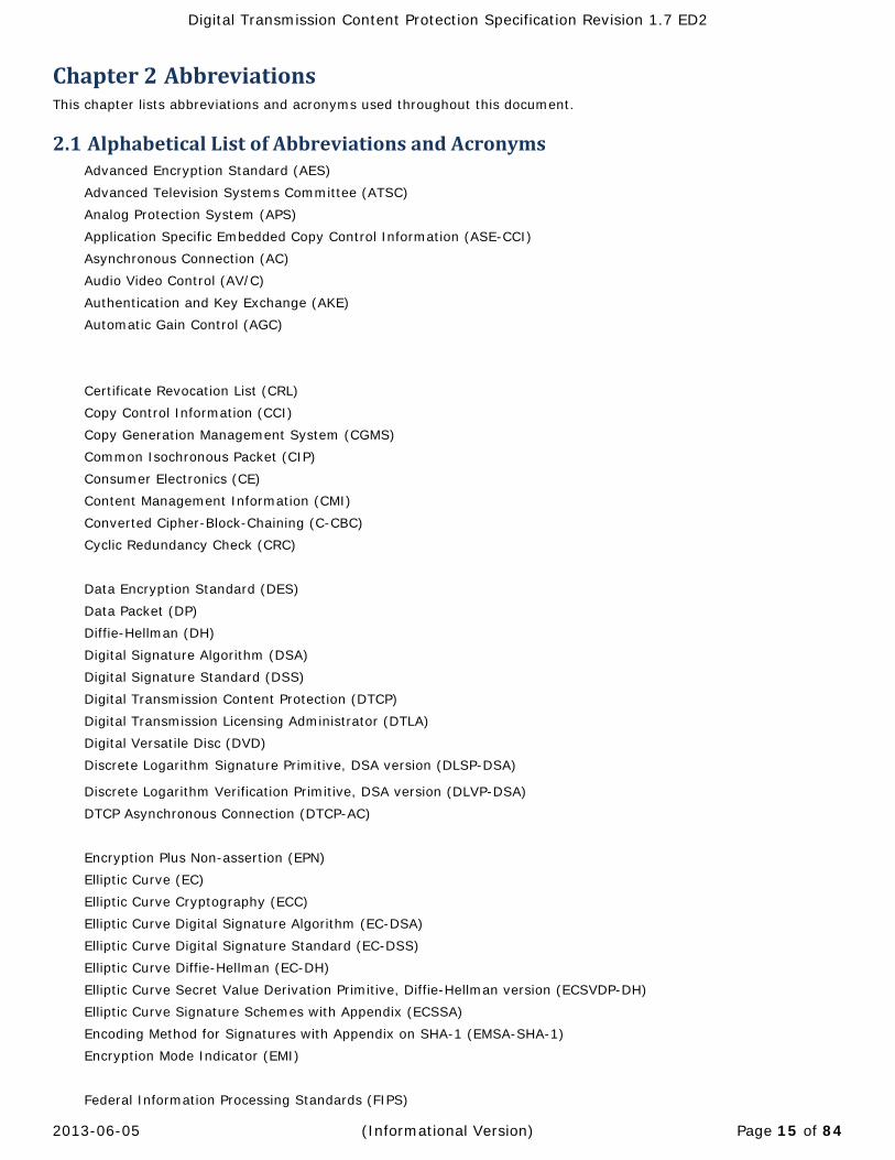
Chapter2 AbbreviationsThis chapter lists abbreviations and acronyms used throughout this document.
2.1 AlphabeticalListofAbbreviationsandAcronymsAdvanced Encryption Standard (AES) Advanced Television Systems Committee (ATSC) Analog Protection System (APS) Application Specific Embedded Copy Control Information (ASE-CCI) Asynchronous Connection (AC) Audio Video Control (AV/C) Authentication and Key Exchange (AKE) Automatic Gain Control (AGC) Certificate Revocation List (CRL) Copy Control Information (CCI) Copy Generation Management System (CGMS) Common Isochronous Packet (CIP) Consumer Electronics (CE) Content Management Information (CMI) Converted Cipher-Block-Chaining (C-CBC) Cyclic Redundancy Check (CRC) Data Encryption Standard (DES) Data Packet (DP) Diffie-Hellman (DH) Digital Signature Algorithm (DSA) Digital Signature Standard (DSS) Digital Transmission Content Protection (DTCP) Digital Transmission Licensing Administrator (DTLA) Digital Versatile Disc (DVD) Discrete Logarithm Signature Primitive, DSA version (DLSP-DSA)
Discrete Logarithm Verification Primitive, DSA version (DLVP-DSA) DTCP Asynchronous Connection (DTCP-AC) Encryption Plus Non-assertion (EPN) Elliptic Curve (EC) Elliptic Curve Cryptography (ECC) Elliptic Curve Digital Signature Algorithm (EC-DSA) Elliptic Curve Digital Signature Standard (EC-DSS) Elliptic Curve Diffie-Hellman (EC-DH) Elliptic Curve Secret Value Derivation Primitive, Diffie-Hellman version (ECSVDP-DH) Elliptic Curve Signature Schemes with Appendix (ECSSA) Encoding Method for Signatures with Appendix on SHA-1 (EMSA-SHA-1) Encryption Mode Indicator (EMI) Federal Information Processing Standards (FIPS)

Digital Transmission Content Protection Specification Revision 1.7 ED2
2013-06-05 (Informational Version) Page 16 of 84
Function Control Protocol (FCP) Home Digital Network Device (HDND) Institute of Electrical and Electronics Engineers (IEEE) International Electrotechnical Commission (IEC) International Electrotechnical Commission Publicly Available Specifications (IEC-PAS) International Organization for Standardization (ISO) Key Selection Vector (KSV) Least Significant Bit (lsb) Least Significant Byte (LSB) Menezes-Okamoto-Vanstone (MOV) Most Significant Bit (msb) Most Significant Byte (MSB) Motion Picture Experts Group (MPEG) National Institute of Standards and Technology (NIST) Personal Computer (PC) Program Management Table (PMT) Protected Content Packet (PCP) Random Number Generator (RNG) Secure Hash Algorithm, revision 1 (SHA-1) Secure Hash Standard (SHS) Set Top Box (STB) Source node ID (SID) System Renewability Message (SRM) Video Cassette Recorder (VCR)
Digital Transmission Content Protection Specification Revision 1.7 ED2
2013-06-05 (Informational Version) Page 17 of 84
Chapter3 TheDigitalTransmissionContentProtectionSystem
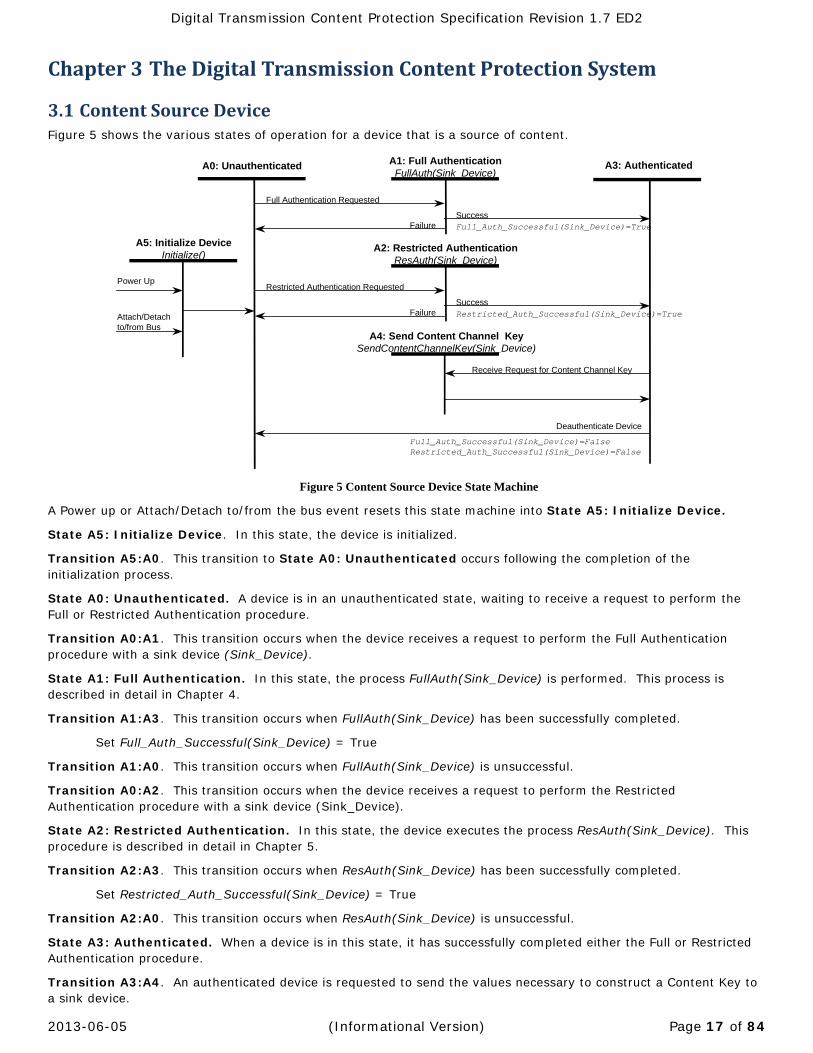
3.1 ContentSourceDeviceFigure 5 shows the various states of operation for a device that is a source of content.
Figure 5 Content Source Device State Machine
A Power up or Attach/Detach to/from the bus event resets this state machine into State A5: Initialize Device.
State A5: Initialize Device. In this state, the device is initialized.
Transition A5:A0. This transition to State A0: Unauthenticated occurs following the completion of the initialization process.
State A0: Unauthenticated. A device is in an unauthenticated state, waiting to receive a request to perform the Full or Restricted Authentication procedure.
Transition A0:A1. This transition occurs when the device receives a request to perform the Full Authentication procedure with a sink device (Sink_Device).
State A1: Full Authentication. In this state, the process FullAuth(Sink_Device) is performed. This process is described in detail in Chapter 4.
Transition A1:A3. This transition occurs when FullAuth(Sink_Device) has been successfully completed.
Set Full_Auth_Successful(Sink_Device) = True
Transition A1:A0. This transition occurs when FullAuth(Sink_Device) is unsuccessful.
Transition A0:A2. This transition occurs when the device receives a request to perform the Restricted Authentication procedure with a sink device (Sink_Device).
State A2: Restricted Authentication. In this state, the device executes the process ResAuth(Sink_Device). This procedure is described in detail in Chapter 5.
Transition A2:A3. This transition occurs when ResAuth(Sink_Device) has been successfully completed.
Set Restricted_Auth_Successful(Sink_Device) = True
Transition A2:A0. This transition occurs when ResAuth(Sink_Device) is unsuccessful.
State A3: Authenticated. When a device is in this state, it has successfully completed either the Full or Restricted Authentication procedure.
Transition A3:A4. An authenticated device is requested to send the values necessary to construct a Content Key to a sink device.
A0: Unauthenticated A1: Full AuthenticationFullAuth(Sink_Device)
A3: Authenticated
Full Authentication Requested
Attach/Detach to/from Bus
A2: Restricted AuthenticationResAuth(Sink_Device)
Restricted Authentication Requested
FailureSuccess
Power Up
FailureSuccess
A5: Initialize DeviceInitialize()
Full_Auth_Successful(Sink_Device)=True
Restricted_Auth_Successful(Sink_Device)=True
Full_Auth_Successful(Sink_Device)=FalseRestricted_Auth_Successful(Sink_Device)=False
Deauthenticate Device
Receive Request for Content Channel Key
A4: Send Content Channel KeySendContentChannelKey(Sink_Device)
Digital Transmission Content Protection Specification Revision 1.7 ED2
2013-06-05 (Informational Version) Page 18 of 84
State A4: Send Content Channel Key. In this state, the source device sends values necessary to create a content key to an authenticated sink device by executing SendContentChannelKey(Sink_Device). This process is described in Chapter 6.
Transition A4:A3. This transition occurs on completion of the process SendContentChannelKey(Sink_Device).
Transition A3:A0.
Set Full_Auth_Successful(Sink_Device) = False
Set Restricted_Auth_Successful(Sink_Device) = False
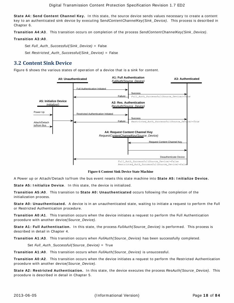
3.2 ContentSinkDeviceFigure 6 shows the various states of operation of a device that is a sink for content.
Figure 6 Content Sink Device State Machine
A Power up or Attach/Detach to/from the bus event resets this state machine into State A5: Initialize Device.
State A5: Initialize Device. In this state, the device is initialized.
Transition A5:A0. This transition to State A0: Unauthenticated occurs following the completion of the initialization process.
State A0: Unauthenticated. A device is in an unauthenticated state, waiting to initiate a request to perform the Full or Restricted Authentication procedure.
Transition A0:A1. This transition occurs when the device initiates a request to perform the Full Authentication procedure with another device(Source_Device).
State A1: Full Authentication. In this state, the process FullAuth(Source_Device) is performed. This process is described in detail in Chapter 4.
Transition A1:A3. This transition occurs when FullAuth(Source_Device) has been successfully completed.
Set Full_Auth_Successful(Source_Device) = True
Transition A1:A0. This transition occurs when FullAuth(Source_Device) is unsuccessful.
Transition A0:A2. This transition occurs when the device initiates a request to perform the Restricted Authentication procedure with another device(Source_Device).
State A2: Restricted Authentication. In this state, the device executes the process ResAuth(Source_Device). This procedure is described in detail in Chapter 5.
A0: Unauthenticated A1: Full AuthenticationFullAuth(Source_Device)
A3: Authenticated
Full Authentication Initiated
Attach/Detach to/from Bus
A2: Res. AuthenticationResAuth(Source_Device)
Restricted Authentication Initiated
FailureSuccess
Power Up
Request Content Channel Key
A4: Request Content Channel KeyRequestContentChannelKey(Source_Device)
FailureSuccess
A5: Initialize DeviceInitialize()
Full_Auth_Successful(Source_Device)=True
Restricted_Auth_Successful(Source_Device)=True
Full_Auth_Successful(Source_Device)=FalseRestricted_Auth_Successful(Source_Device)=False
Deauthenticate Device
Digital Transmission Content Protection Specification Revision 1.7 ED2
2013-06-05 (Informational Version) Page 19 of 84
Transition A2:A3. This transition occurs when ResAuth(Source_Device) has been successfully completed.
Set Restricted_Auth_Successful(Source_Device) = True
Transition A2:A0. This transition occurs when ResAuth(Source_Device) is unsuccessful.
State A3: Authenticated. When a device is in this state, it has successfully completed either the Full or Restricted Authentication procedure.
Transition A3:A4. An authenticated device needs to request a Content Key to gain access to copy protected content.
State A4: Request Content Channel Key. In this state, an authenticated sink device requests the values necessary to create a Content Key by executing the process RequestContentChannelKey(Source_Device). This process is described in Chapter 6.
Transition A4:A3. This transition occurs on completion of the process RequestContentChannelKey(Source_Device).
Transition A3:A0.
Set Full_Auth_Successful(Source_Device) = False
Set Restricted_Auth_Successful(Source_Device) = False
Digital Transmission Content Protection Specification Revision 1.7 ED2
2013-06-05 (Informational Version) Page 20 of 84
Chapter4 FullAuthentication
4.1 IntroductionThis chapter addresses the particulars of the Full Authentication level of device authentication and key exchange. Full Authentication employs the public key based Elliptic Curve Digital Signature Algorithm (EC-DSA) for signing and verification. It also employs the Elliptic Curve Diffie-Hellman (EC-DH) key exchange algorithm to generate a shared authentication key.
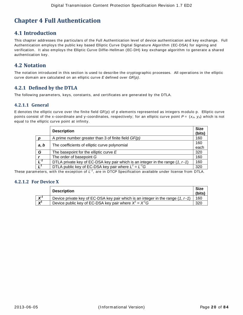
4.2 NotationThe notation introduced in this section is used to describe the cryptographic processes. All operations in the elliptic curve domain are calculated on an elliptic curve E defined over GF(p).
4.2.1 DefinedbytheDTLAThe following parameters, keys, constants, and certificates are generated by the DTLA.
4.2.1.1 GeneralE denotes the elliptic curve over the finite field GF(p) of p elements represented as integers modulo p. Elliptic curve points consist of the x-coordinate and y-coordinates, respectively; for an elliptic curve point P = (xP, yP) which is not equal to the elliptic curve point at infinity.
Description Size (bits)
p A prime number greater than 3 of finite field GF(p) 160
a, b The coefficients of elliptic curve polynomial 160 each
G The basepoint for the elliptic curve E 320 r The order of basepoint G 160 L-1 DTLA private key of EC-DSA key pair which is an integer in the range (1, r1) 160 L1 DTLA public key of EC-DSA key pair where L1 = L-1G 320
These parameters, with the exception of L-1, are in DTCP Specification available under license from DTLA.
4.2.1.2 ForDeviceX
Description Size (bits)
X-1 Device private key of EC-DSA key pair which is an integer in the range (1, r1) 160 X1 Device public key of EC-DSA key pair where X1 = X-1G 320

Digital Transmission Content Protection Specification Revision 1.7 ED2
2013-06-05 (Informational Version) Page 21 of 84
4.2.2 NotationusedduringFullAuthenticationThe following additional values are generated and used by the devices during Full Authentication:
Key or Variable
Description Size (bits)
Xn Nonce (random challenge generated by RNGF) 128
XK Random value used in EC-DH key exchange generated by RNGF in the device (integer in the range [1, r-1])
160
XV EC-DH first phase value (XKG) calculated in the device (point on the elliptic curve E)
320
XSRMV Version number of the system renewability message (SRMV) stored by the device (See Chapter 7)
16
XSRMC
Indicates the number of SRM part(s) which are currently stored in the non-volatile memory of the device. A value of SRMC indicates that the first SRMC+1 generations of SRMs are currently stored by the device (See Chapter 7)
4
KAUTH Authentication key which is the least significant 96-bits of shared data created through EC-DH key exchange
96
Table 1 Length of keys and variables generated by the device (Full Authentication)
4.2.3 DeviceCertificateFormatsA device certificate is given to each compliant device X by the DTLA and is referred to as XCERT. This certificate is stored in the compliant device and used during the authentication process.

Digital Transmission Content Protection Specification Revision 1.7 ED2
2013-06-05 (Informational Version) Page 22 of 84
4.2.3.1 BaselineFormatThe following Figure 7 shows the baseline device certificate format:
31 30 29 28 27 26 25 24 23 22 21 20 19 18 17 16 15 14 13 12 11 10 9 8 7 6 5 4 3 2 1 0 Certificate
Type Format Dev Gen Reserved (zero) AL AP Device ID
Device ID continued (Total 40bits)
Device EC-DSA Public Key (320 bits)
DTLA EC-DSA signature of all preceding fields (320 bits for c and followed by d value)
Figure 7 Baseline Device Certificate Format
Device certificates are comprised of the following Baseline Format fields:
Certificate Type (4 bits). The only encoding which is currently defined is 0, which indicates the DTCP certificate. All other encodings are currently reserved.
Certificate Format (4 bits). This field specifies the format for a specific type of certificate. Currently three formats are defined:
o Format 0 = the Restricted Authentication device certificate format (See Chapter 5). o Format 1 = the Baseline Full Authentication device certificate format. o Format 2 = the Extended Full Authentication device certificate format (NOT ESTABLISHED2). o Other encodings are currently reserved.
Device Generation (XSRMG, 4 bits). This field indicates the non-volatile memory capacity and therefore the maximum generation of renewability messages that this device supports (Described in Chapter 7). The encoding 0 indicates that the device shall have a non-volatile memory capacity for storing First-Generation SRM. The encoding 1 indicates that the device shall have a non-volatile memory capacity for storing Second-Generation SRM.
Reserved Field (10 bits). These bits are reserved for future definition and are currently defined to have a value of zero.
AL flag (1 bit). Additional Localization flag. The AL flag is set to value of one to indicate that the associated device is capable of performing the additional localization test, otherwise shall be set to value of zero.
AP flag (1 bit). Authentication Proxy flag. A device certificate with an AP flag value of one is used by a DTCP bus bridge device, which receives a content stream using a sink function and retransmits that stream to another bus using a source function3. The procedures for processing this field are specified in Appendix C.
The device’s ID number (XID, 40 bits) assigned by the DTLA.
The EC-DSA public key of the device (X1, 320 bits)
An EC-DSA signature from the DTLA of the components listed above (320 bits)
The overall size of a Baseline Format device certificate is 88 bytes.
2 See section 1.10
3 To maintain consistency with the previous version of this specification, the value of AP flag for a device with a common device certificate is set to one regardless of the DTCP bus bridge capability.

Digital Transmission Content Protection Specification Revision 1.7 ED2
2013-06-05 (Informational Version) Page 23 of 84
4.2.3.2 ExtendedFormatFields(NOTESTABLISHED2ComponentsoftheDeviceCertificate)In addition to the Baseline Format fields, each device certificate may optionally include the following Extended Format fields2:
A device capability mask indicating the properties of the device and channel ciphers supported. (XCap_Mask, 32 bits)
An EC-DSA signature from the DTLA of all preceding components in the device certificate. (320 bits)
31 30 29 28 27 26 25 24 23 22 21 20 19 18 17 16 15 14 13 12 11 10 9 8 7 6 5 4 3 2 1 0Baseline Full Authentication Device Certificate Fields (Figure 7)
Device Capability Mask (32 bits) DTLA EC-DSA signature of all preceding fields (320 bits, c followed by d value)
Figure 8 Extended Device Certificate Fields
Device Capability Mask
The device capability mask is provided to describe the extensibility features supported by a given device.
bit[0] denotes AES-128 capability when b[0]=1 the device has optional cipher AES-128 capability and when b[0]=0 then it does not.
bit[31..1] are reserved.
Devices that do not support the device capability mask are assumed to only support the baseline cryptographic features defined by this content protection system (e.g., the 56-bit M6 Baseline Cipher).
4.3 ManufactureofCompliantDevicesAll compliant devices that support Full Authentication (that is, each item manufactured, regardless of brand and model) will be assigned a unique Device ID (XID) and device EC-DSA public/private key pair (X1, X-1) generated by the DTLA. X-1 must be stored within the device in such a way as to prevent its disclosure. Compliant devices must also be given a device certificate (XCERT) by the DTLA. This certificate is stored in the compliant device and used during the authentication process. In addition, the compliant device will need to store the other constants and keys necessary to implement the cryptographic protocols.
Digital Transmission Content Protection Specification Revision 1.7 ED2
2013-06-05 (Informational Version) Page 24 of 84
4.4 CryptographicFunctions
4.4.1 SHA‐1(SecureHashAlgorithm,revision1)SHA-1, as described in FIPS PUB 180-24 is the algorithm used in DSS to generate a message digest of length 160 bits. A message digest is a value calculated from message. It is similar in concept to a checksum, but computationally infeasible to forge.
4.4.2 RandomNumberGeneratorA high quality random number generator is required for Full Authentication. The output of this random number generator is indicated by the function RNGF that is described in DTCP Specification available under license from DTLA.
4.4.3 EllipticCurveCryptography(ECC)These cryptographic algorithms are based upon cryptographic schemes, primitives, and encoding methods described in IEEE 1363-2000.
An Elliptic Curve Cryptosystem (ECC) is used as the cryptographic basis for DH and DSA.
The definition field classifies ECC implementations. For this system, the definition field used is GF(p) where p is a large prime number greater than three. An elliptic curve E over the field GF(p), where p > 3, is defined by the parameters a and b and the set of solutions (x, y) to the elliptic curve equation together with an extra point often called the point at infinity. The point at infinity is the identity element of the abelian group, (E, +). The elliptic curve equation used is
y2 = x3 + ax + b where 4a3 + 27b2 0,
Where a, b, x, y, are elements of GF(p). A point P on the elliptic curve consists of the x-coordinate and the y-coordinate of a solution to this equation, or the point at infinity, and is designated P = (xp, yp).
For EC-DSA and EC-DH, a basepoint G on the elliptic curve is selected. All operations in the elliptic curve domain are calculated on an elliptic curve E defined over GF(p). The public key Y1 (a point on the elliptic curve) and private key Y-
1 (a scalar value satisfying 0 < Y-1 < r) for each entity satisfies the equation:
Y1 = Y-1 G
In specifying the elliptic curve used:
The order of basepoint G will have a large prime factor.
The system will be robust against MOV reduction attack, since super singular elliptic curves are avoided.
4 National Institute of Standards and Technology (NIST), “Secure Hash Standard (SHS),” FIPS Publication 180-2 , August 1, 2002.

Digital Transmission Content Protection Specification Revision 1.7 ED2
2013-06-05 (Informational Version) Page 25 of 84
4.4.3.1 EllipticCurveDigitalSignatureAlgorithm(EC‐DSA)
Signature The following signature algorithm is based on the ECSSA digital signature scheme using the DLSP-DSA signature primitive and EMSA-SHA-1 encoding method defined in of IEEE 1363-2000.
Input:
M = the data to be signed
X-1 = the private key of the signing device (must be kept secret)
p, a, b, G, and r = the elliptic curve parameters associated with X-1
Output:
SX-1[M] = a 320-bit signature of the data, M, based on the private key, X-1
Algorithm:
Step 1, Generate a random value, u, satisfying 0 < u < r, using RNGF. A new value for u is generated for every signature and shall be unpredictable to an adversary for every signature computation. Also, calculate the elliptic curve point, V = uG.
Step 2, Calculate c = xV mod r (the x-coordinate of V reduced modulo r). If c = 0, then go to Step 1.
Step 3, Calculate f = [SHA-1(M)]msb_bits_in_r. That is, calculate the SHA-1 hash of M and then take the most significant bits of the message digest that is the same number of bits as the size of r.
Step 4, Calculate d = [u-1(f + cX-1)] mod r (note that u-1 is the modular inverse of u mod r while X-1 is the private key of the signing device). If d = 0, then go to Step 1.
Step 5, Set first 160 bits of SX-1[M] equal to the big endian representation of c, and the second 160 bits of SX-
1[M] equal to the big endian representation of d. (SX-1[M] = c || d)
Verification The following verification algorithm is based on the ECSSA digital signature scheme using the DLVP-DSA signature primitive and EMSA-SHA-1 encoding method defined in of IEEE 1363-2000.
Input:
SX-1[M] = an alleged 320-bit signature (c || d) of the data, M, based on the private key, X-1
M = the data associated with the signature
X1 = the public key of the signing device
p, a, b, G, and r = the elliptic curve parameters associated with X-1
Output:
“valid” or “invalid”, indicating whether the alleged signature is determined to be valid or invalid, respectively
Algorithm:
Step 1, Set c equal to the first 160 bits of SX-1[M] interpreted as in big endian representation, and d equal to the second 160 bits of SX-1[M] interpreted as in big endian representation. If c is not in the range [1, r – 1] or d is not in the range [1, r – 1], then output “invalid” and stop.
Step 2, Calculate f = [SHA-1(M)]msb_bits_in_r. That is, calculate the SHA-1 hash of M and then take the most significant bits of the message digest that is the same number of bits as the size of r.
Step 3, Calculate h = d-1 mod r, h1 = (fh) mod r, and h2 = (ch) mod r.
Step 4, Calculate the elliptic curve point P = (xP, yP) = h1G + h2X1. If P equals the elliptic curve point at infinity, then output “invalid” and stop.
Step 5, Calculate c’ = xP mod r. If c’ = c, then output “valid”; otherwise, output “invalid.”

Digital Transmission Content Protection Specification Revision 1.7 ED2
2013-06-05 (Informational Version) Page 26 of 84
4.4.3.2 EllipticCurveDiffie‐Hellman(EC‐DH)The following shared secret derivation algorithm is based on the ECSVDP-DH primitive defined in IEEE 1363-2000.
Input:
YV = the Diffie-Hellman first phase value generated by the other device (an elliptic curve point)
p, a, b, G, and r = the elliptic curve parameters associated with X-1
Output:
XV = the Diffie-Hellman first phase value (an elliptic curve point)
the x-coordinate of XKYV = the shared secret generated by this algorithm (must be kept secret from third parties)
Algorithm:
Step 1, Generate a random integer, XK, in the range [1, r-1] using RNGF. A new value for XK is generated for every shared secret and shall be unpredictable to an adversary. Also, calculate the elliptic curve point, XV = XKG.
Step 2, Output XV.
Step 3, Calculate XKYV. Output the x-coordinate of XKYV as the secret shared.
4.4.3.3 ImplementationoftheEllipticCurveCryptosystemA range of implementations of the Elliptic Curve Cryptosystem can be realized which are compatible with the IEEE 1363 primitives described in this section.
Efficient implementations of an elliptic curve cryptosystem can be realized by performing computations within the Montgomery space using new definitions of the basic arithmetic operations of addition, subtraction, multiplication, and inverse5.
5 Japanese patent application number: PH10-269060.

Digital Transmission Content Protection Specification Revision 1.7 ED2
2013-06-05 (Informational Version) Page 27 of 84
4.5 ProtocolFlow
4.5.1 ProtocolFlowOverviewThe following Figure 9 gives an overview of the Full Authentication protocol flow.
Figure 9 Full Authentication Protocol Flow Overview
During Full Authentication:
1. The sink device requests authentication by sending a random challenge and its device certificate. This can be the result of the sink device attempting to access a protected content stream (whose EMI is set to “Copy-never,” “No-more-copies,” or “Copy-one-generation”). The sink device may request authentication on a speculative basis, before attempting to access a content stream. If a sink device attempts speculative authentication, the request can be rejected by the source.
2. Device A then returns a random challenge and its device certificate. If the value of the other device’s certificate type or format fields is reserved, the authentication should be immediately aborted. After the random challenge and device certificate exchange, each device verifies the integrity of the other device’s certificate using EC-DSA. If the DTLA signature is determined to be valid, the devices examine the certificate revocation list embedded in their system renewability messages (see Chapter 7) to verify that the other device has not been revoked. If the other device has not been revoked, each device calculates a EC-DH key exchange first-phase value (See section 4.4.3.2).
3. The devices then exchange messages containing the EC-DH key exchange first-phase value, the Renewability Message Version Number and Generation of the system renewability message stored by the device, and a message signature containing the other device’s random challenge concatenated to the preceding components. The devices verify the signed messages received by checking the message signature using EC-DSA with the other device’s public key. This verifies that the message has not been tampered with. If the signature cannot be verified, the device refuses to continue. In addition, by comparing the exchanged version numbers, devices can at a later time invoke the system renewability mechanisms (See Section 7.2 for the details of this procedure).
Each device calculates an authentication key by completing the EC-DH key exchange.
A detailed description of the Full Authentication protocol and associated state machine can be found in the DTCP Specification available under license from DTLA.
Digital Transmission Content Protection Specification Revision 1.7 ED2
2013-06-05 (Informational Version) Page 28 of 84
Chapter5 RestrictedAuthentication
5.1 IntroductionThis chapter describes the authentication and key exchange between source and sink devices that employ asymmetric key management and common key cryptography for “Copy-one-generation” and “No-more-copy” contents. These kinds of devices, which typically have limited computation resources, follow a Restricted Authentication protocol instead of Full Authentication. Restricted Authentication relies on the use of shared secrets and hash function to respond to a random challenge.
The Restricted Authentication method is based on a device being able to prove that it holds a secret shared with other devices. One device authenticates another by issuing a random challenge that is responded to by modifying it with the shared secret and hashing.
5.2 NotationThe notation introduced in this section is used to describe the cryptographic process and protocol used for Restricted Authentication.
5.2.1 DefinedbytheDTLAThe following parameters, keys, constants, and certificates must be generated by the DTLA.
5.2.1.1 GeneralThe parameters defined in Section 4.2.1 are also used during Restricted Authentication by Source devices that also support Full Authentication.

Digital Transmission Content Protection Specification Revision 1.7 ED2
2013-06-05 (Informational Version) Page 29 of 84
5.2.1.2 ForDeviceXA device certificate (XCERT) given to compliant device X by the DTLA and used during the authentication process (See the Section 5.2.3 for details).
Description Size (bits)
“Copy-one-generation” Sink Device Keys (XKcosnk1…XKcosnk12)
Each device which is a sink of “Copy-one-generation” content receives 12 64 bit keys from the DTLA.
64 (Each)
“Copy-one-generation” Source Device Keys (XKcosrc1…XKcosrc12)
Each device which is a source of “Copy-one-generation” content receives 12 64 bit keys from the DTLA.
64 (Each)
“No-more-copies” Sink Device Keys (XKnmsnk1…XKnmsnk12)
Each device which is a sink of “No-more-copies” content receives 12 64 bit keys from the DTLA.
64 (Each)
“No-more-copies” Source Device Keys
(XKnmsrc1…XKnmsrc12)
Each device which is a source of “No-more-copies” content receives 12 64 bit keys from the DTLA.
64 (Each)
Key Selection Vector (XKSV)
This key selection vector (KSV) determines which keys will be used during the Restricted Authentication procedure with this device. Only one KSV is required for devices that can be both a source and sink of content.
12
Table 2 Length of Keys and Constants created by DTLA (Restricted Authentication)
Devices contain the keys appropriate to the type of content and functions that they perform.
5.2.2 NotationusedduringRestrictedAuthenticationThe following additional values are generated and used by the devices during Restricted Authentication:
Description Size (bits) (An, Bn) Nonce (random challenge generated by RNGR) 64 (Kv, K’v) Verification Keys 64 (R, R’) Responses 64 (KAUTH, K’AUTH) Authentication Keys 96
Table 3 Length of keys and variables generated by the device (Restricted Authentication)

Digital Transmission Content Protection Specification Revision 1.7 ED2
2013-06-05 (Informational Version) Page 30 of 84
5.2.3 DeviceCertificateFormatA Restricted Authentication Device Certificate is used in the Restricted Authentication process. Each Restricted Authentication device certificate is assigned by the DTLA and includes a Device ID and a signature generated by the DTLA. All compliant sink devices that support only Restricted Authentication shall have this certificate. Figure 10 shows this device certificate format.
31 30 29 28 27 26 25 24 23 22 21 20 19 18 17 16 15 14 13 12 11 10 9 8 7 6 5 4 3 2 1 0
Certificate Type Format Reserved (zero) AL Key Selection Vector Device ID
Device ID continued (Total 40 bits) DTLA EC-DSA signature of all preceding fields (320 bits for c and follow by d value)
Figure 10 Restricted Authentication Device Certificate Format
The Restricted Authentication device certificate is comprised of the following fields:
Certificate Type (4 bits). (See Section 4.2.3.1 for a description of the encoding)
Certificate Format (4 bits). (See Section 4.2.3.1 for a description of the encoding)
Reserved Field (3 bits). These bits are reserved for future definition and are currently defined to have a value of zero.
AL flag (1 bit). Additional Localization flag. The AL flag is set to value of one to indicate that the associated device is capable of performing the additional localization test, otherwise shall be set to value of zero.
Key Selection Vector (XKSV, 12 bits) assigned by the DTLA. This vector determines which keys will be used during the Restricted Authentication procedure with this device. This KSV is used regardless of the EMI of the stream to be handled or whether the device is being used as a source or sink of content. The encoding of this field is as follows:
Figure 11 Key Selection Vector
The Device ID number (XID, 40 bits) assigned by the DTLA.
A EC-DSA signature from the DTLA of the components listed above (320 bits)
The overall size of a Restricted Authentication device certificate format is 48 bytes.
5.2.4 RandomNumberGeneratorA random number generator is required for Restricted Authentication. The output of this random number generator is indicated by the function RNGR. Either RNGR or RNGF as described in DTCP Specification available under license from DTLA.
11109 1 0235 4678
XK12 Selected
Key Selection Vector
XK1 Selected
...XK2 Selected
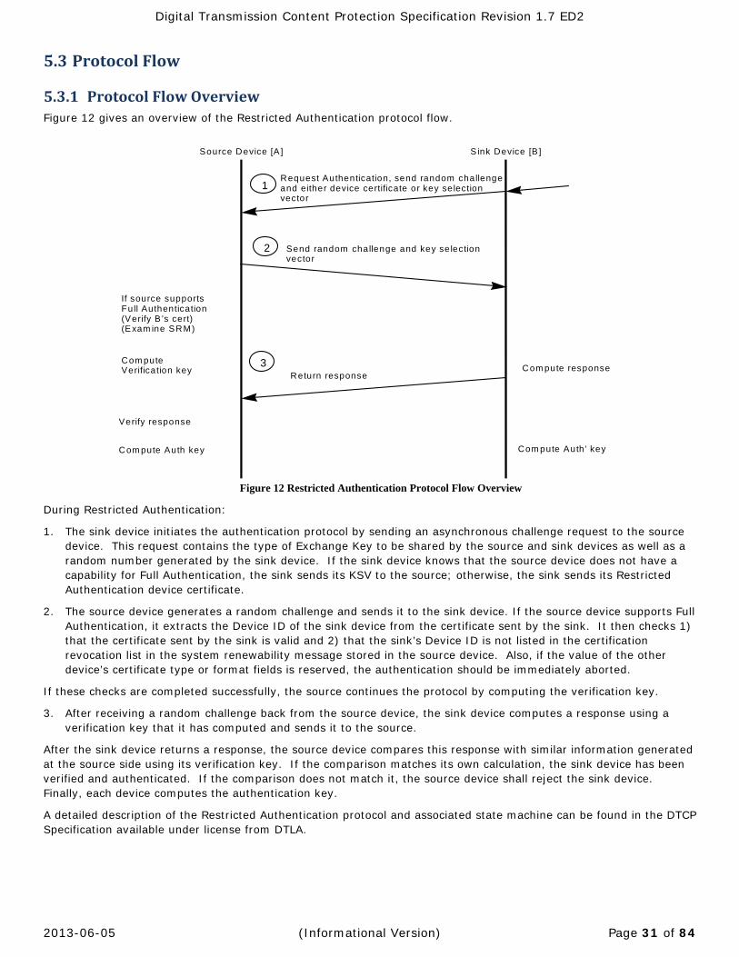
Digital Transmission Content Protection Specification Revision 1.7 ED2
2013-06-05 (Informational Version) Page 31 of 84
5.3 ProtocolFlow
5.3.1 ProtocolFlowOverviewFigure 12 gives an overview of the Restricted Authentication protocol flow.
Request Authentication, send random challengeand either device certificate or key se lectionvector
1
2
Source Device [A ] S ink Device [B ]
3
Send random challenge and key se lectionvector
Return response
Com puteVerification key Com pute response
Com pute Auth ’ keyCom pute Auth key
Verify response
If source supportsFull Authentication(Verify B ’s cert)(Exam ine SRM)
Figure 12 Restricted Authentication Protocol Flow Overview
During Restricted Authentication:
1. The sink device initiates the authentication protocol by sending an asynchronous challenge request to the source device. This request contains the type of Exchange Key to be shared by the source and sink devices as well as a random number generated by the sink device. If the sink device knows that the source device does not have a capability for Full Authentication, the sink sends its KSV to the source; otherwise, the sink sends its Restricted Authentication device certificate.
2. The source device generates a random challenge and sends it to the sink device. If the source device supports Full Authentication, it extracts the Device ID of the sink device from the certificate sent by the sink. It then checks 1) that the certificate sent by the sink is valid and 2) that the sink’s Device ID is not listed in the certification revocation list in the system renewability message stored in the source device. Also, if the value of the other device’s certificate type or format fields is reserved, the authentication should be immediately aborted.
If these checks are completed successfully, the source continues the protocol by computing the verification key.
3. After receiving a random challenge back from the source device, the sink device computes a response using a verification key that it has computed and sends it to the source.
After the sink device returns a response, the source device compares this response with similar information generated at the source side using its verification key. If the comparison matches its own calculation, the sink device has been verified and authenticated. If the comparison does not match it, the source device shall reject the sink device. Finally, each device computes the authentication key.
A detailed description of the Restricted Authentication protocol and associated state machine can be found in the DTCP Specification available under license from DTLA.

Digital Transmission Content Protection Specification Revision 1.7 ED2
2013-06-05 (Informational Version) Page 32 of 84
Chapter6 ContentChannelManagementandProtection
6.1 IntroductionThis chapter details the mechanisms used to 1) share an Exchange Key between a source device and a sink device and 2) establish and manage the encrypted isochronous channel through which protected content flows. Either Full or Restricted Authentication (depending on the capabilities of the device) shall be completed prior to establishing a content channel.
6.2 ContentManagementKeys
6.2.1 ExchangeKey(KX)andSessionExchangeKey(KS)Either Exchange Key (KX) or Session Exchange Key (KS) is used to calculate a content key (KC) to encrypt content. Note that KX and KS are collectively described as the “Exchange Key” if “(KX)” or “(KS)” is not accompanied.
6.2.1.1 ExchangeKeys(KX)A common set of Exchange Keys (KX) are established between a source device and all sink devices that have completed the appropriate authentication procedure (either Full or Restricted) with the source device required to handle content with a specific EMI value (Section 6.4.2).
A single exchange key shall be used for all EMI values for an optional content cipher.
The procedure for establishing an Exchange Key (KX) is described in Section 6.3.1.
6.2.1.2 SessionExchangeKeys(KS)Session Exchange Keys (KS) are unique for each connected sink device while the Exchange Key (KX) is common to all connected sink devices. Support of the Session Exchange Key is not mandated and the Session Exchange Key is established when both a source device and a sink device support Session Exchange Key. Session Exchange Key can be used for the transmission of content which shall not be sent to multiple sink devices. Session Exchange Key can also be used for the transmission of content which can be sent using Exchange Key (KX).
The following rules shall be applied to Session Exchange Key.
A single Session Exchange Key shall be used for all EMI values. Source devices shall provide Session Exchange Key only with the Full authentication procedure. Source devices must ensure that all of the values of the Session Exchange Keys (KS) and Exchange Keys (KX) are
different. Source devices must ensure that the Session Exchange Key used for each authenticated sink device is unique.
o Source devices may send the same value of the available Session Exchange Key to a sink device with the same value of Device ID and AP flag value of zero in the sink’s device certificate.
o Source devices may send the same value of the available Session Exchange Key to sink device with a common device certificate by using IDU along withinstead of Device ID.
o Source devices shall not send the same value of the available Session Exchange Key to a sink device with AP flag value of one in the sink’s device certificate unless the source device can uniquely identify the sink device by using IDU along with Device ID.
Source devices during content transmission may swap the active exchange key as desired between the Exchange Key (KX) or Session Exchange Key (KS).
In addition to the above rules, the same rules as Exchange Keys (KX) shall be independently applied to each Exchange Keys (KS) unless otherwise noted.
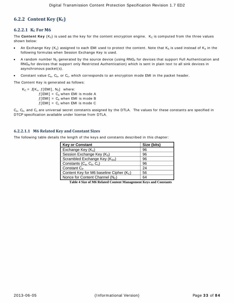
Digital Transmission Content Protection Specification Revision 1.7 ED2
2013-06-05 (Informational Version) Page 33 of 84
6.2.2 ContentKey(KC)
6.2.2.1 KCForM6The Content Key (KC) is used as the key for the content encryption engine. KC is computed from the three values shown below:
An Exchange Key (Kx) assigned to each EMI used to protect the content. Note that KS is used instead of KX in the following formulas when Session Exchange Key is used.
A random number NC generated by the source device (using RNGF for devices that support Full Authentication and RNGR for devices that support only Restricted Authentication) which is sent in plain text to all sink devices in asynchronous packet(s).
Constant value Ca, Cb, or Cc, which corresponds to an encryption mode EMI in the packet header.
The Content Key is generated as follows:
KC = J[Kx, ƒ[EMI], NC] where:
ƒ[EMI] = Ca when EMI is mode A ƒ[EMI] = Cb when EMI is mode B ƒ[EMI] = Cc when EMI is mode C
Ca, Cb, and Cc are universal secret constants assigned by the DTLA. The values for these constants are specified in DTCP specification available under license from DTLA.
6.2.2.1.1 M6RelatedKeyandConstantSizesThe following table details the length of the keys and constants described in this chapter:
Key or Constant Size (bits) Exchange Key (KX) 96 Session Exchange Key (KS) 96 Scrambled Exchange Key (KSX) 96 Constants (Ca, Cb, Cc) 96 Constant CP 24 Content Key for M6 baseline Cipher (KC) 56 Nonce for Content Channel (NC) 64
Table 4 Size of M6 Related Content Management Keys and Constants

Digital Transmission Content Protection Specification Revision 1.7 ED2
2013-06-05 (Informational Version) Page 34 of 84
6.2.2.2 KCforAES‐128The Content Key (KC) is used as the key for the content encryption engine. KC is computed from the three values shown below:
Exchange Key (KX) that is used for all EMIs to protect the content. Note that KS is used instead of KX in the following formulas when Session Echange Key is used.
A random number NC generated by the source device using RNGF which is sent in plain text to all sink devices in asynchronous packet(s).
Constant value Ca, Cb, or Cc which corresponds to an EMI value in the packet header.
The Content Key is generated as follows:
KC = J-AES(KX, ƒ[EMI], NC) Where:
ƒ[EMI] { ƒ[EMI]=Ca when EMI = Mode A ƒ[EMI]=Cb when EMI = Mode B ƒ[EMI]=Cc when EMI = Mode C }
Ca, Cb, and Cc are universal secret constants assigned by the DTLA. The values for these constants are specified in DTCP specification available under license from DTLA.
6.2.2.2.1 AES‐128RelatedKeyandConstantSizesThe following table details the length of the keys and constants described in this chapter:
Key or Constant Size (bits) Exchange Key (KX) 96 Session Exchange Key (KS) 96 Scrambled Exchange Key (KSX) 96 Constants (Ca, Cb, Cc) 96 Initialization Vector Constant (IVC) see 6.6.2.1 64 Content Key for AES-128 Optional Cipher6 (KC) 128 Nonce for Content Channel (NC) 64
Table 5 Length of Keys and Constants (Content Channel Management)
6 NOT ESTABLISHED see section 1.10
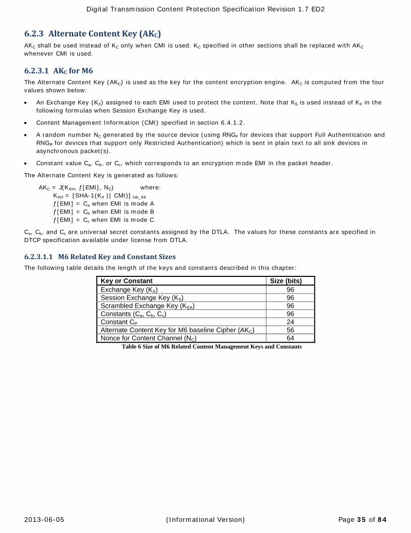
Digital Transmission Content Protection Specification Revision 1.7 ED2
2013-06-05 (Informational Version) Page 35 of 84
6.2.3 AlternateContentKey(AKC)AKC shall be used instead of KC only when CMI is used. KC specified in other sections shall be replaced with AKC whenever CMI is used.
6.2.3.1 AKCforM6The Alternate Content Key (AKC) is used as the key for the content encryption engine. AKC is computed from the four values shown below:
An Exchange Key (KX) assigned to each EMI used to protect the content. Note that KS is used instead of KX in the following formulas when Session Exchange Key is used.
Content Management Information (CMI) specified in section 6.4.1.2.
A random number NC generated by the source device (using RNGF for devices that support Full Authentication and RNGR for devices that support only Restricted Authentication) which is sent in plain text to all sink devices in asynchronous packet(s).
Constant value Ca, Cb, or Cc, which corresponds to an encryption mode EMI in the packet header.
The Alternate Content Key is generated as follows:
AKC = J(KXH, ƒ[EMI], NC) where: KXH = [SHA-1(KX || CMI)] lsb_96 ƒ[EMI] = Ca when EMI is mode A ƒ[EMI] = Cb when EMI is mode B ƒ[EMI] = Cc when EMI is mode C
Ca, Cb, and Cc are universal secret constants assigned by the DTLA. The values for these constants are specified in DTCP specification available under license from DTLA.
6.2.3.1.1 M6RelatedKeyandConstantSizesThe following table details the length of the keys and constants described in this chapter:
Key or Constant Size (bits) Exchange Key (KX) 96 Session Exchange Key (KS) 96 Scrambled Exchange Key (KSX) 96 Constants (Ca, Cb, Cc) 96 Constant CP 24 Alternate Content Key for M6 baseline Cipher (AKC) 56 Nonce for Content Channel (NC) 64
Table 6 Size of M6 Related Content Management Keys and Constants

Digital Transmission Content Protection Specification Revision 1.7 ED2
2013-06-05 (Informational Version) Page 36 of 84
6.2.3.2 AKCforAES‐128The Alternate Content Key (AKC) is used as the key for the content encryption engine. AKC is computed from the four values shown below:
Exchange Key KX assigned to each EMI used to protect the content. Note that KS is used instead of KX in the following formulas when Session Exchange Key is used.
Content Management Information (CMI) specified in section 6.4.1.2.
A random number NC generated by the source device using RNGF which is sent in plain text to all sink devices in asynchronous packet(s).
Constant value Ca, Cb, or Cc which corresponds to an EMI value in the packet header.
The Alternate Content Key is generated as follows:
AKC = J-AES(KXH, ƒ[EMI], NC) Where: KXH = [SHA-1(KX || CMI)] lsb_96 ƒ[EMI] { ƒ[EMI]=Ca when EMI = Mode A ƒ[EMI]=Cb when EMI = Mode B ƒ[EMI]=Cc when EMI = Mode C }
Ca, Cb, and Cc are universal secret constants assigned by the DTLA. The values for these constants are specified in DTCP specification available under license from DTLA.
6.2.3.2.1 AES‐128RelatedKeyandConstantSizesThe following table details the length of the keys and constants described in this chapter:
Key or Constant Size (bits) Exchange Key (KX) 96 Session Exchange Key (KS) 96 Scrambled Exchange Key (KSX) 96 Constants (Ca, Cb, Cc) 96 Initialization Vector Constant (IVC) see 6.6.2.1 64 Alternate Content Key for AES-128 Optional Cipher7 (AKC) 128 Nonce for Content Channel (NC) 64
Table 7 Length of Keys and Constants (Content Channel Management)
7 NOT ESTABLISHED See section 1.10

Digital Transmission Content Protection Specification Revision 1.7 ED2
2013-06-05 (Informational Version) Page 37 of 84
6.3 ProtocolFlow
6.3.1 EstablishingExchangeKeyAfter the completion of Full or Restricted Authentication, the source device establishes the Exchange Key(s) described in Section 6.2.1. The following procedure is used for each key:
1. The source device assigns a random value for the particular Exchange Key (Kx) (using RNGF for devices that support Full Authentication and RNGR for devices that support only Restricted Authentication) being established.
2. It then scrambles the key KX using KAUTH resulting in KSX according to the function described in the DTCP Specification available under license from the DTLA.
3. The source device sends KSX to the sink device.
4. The sink device descrambles the KSX using K’AUTH (calculated during Authentication) to determine the shared Exchange Key Kx according to the function described in the DTCP Specification available under license from DTLA.
The source device repeats the above steps for all of the Exchange Keys required between it and the sink device.
Finally, the devices update the SRM if it is determined to be necessary during the Full Authentication process (see Chapter 4). The update procedure is described in Section 7.2.1.
Devices remain authenticated as long as they maintain valid Exchange Keys. The Exchange Key may be repeatedly used to set up and manage the security of copyrighted content streams without further authentication. It is recommended that source devices expire their Exchange Keys when they stop all isochronous output. Additionally, both source and sink devices must expire their Exchange Keys when they are detached from the bus (i.e. enter “isolated” state as described in section 3.7.3.1.1 of IEEE std 1394-1995). The process for expiring Exchange Keys is described Section 8.3.4.3.
6.3.2 EstablishingSessionExchangeKeyTo establish the Session Exchange Key (KS), the same procedure specified in Section 6.3.1 is used to establish the Session Exchange Key (KS) except that KS may only be exchanged using Full Authentication independent of procedure for the Exchange Key (KX). Source devices are prohibited from sending both KS and KX with a single AKE procedure. Sink devices send CHALLENGE subfunction with exchange_key field in which the bit for Session Exchange Key (KS) is set.
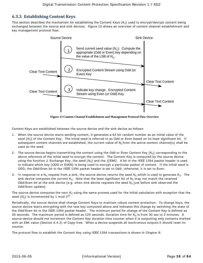
Digital Transmission Content Protection Specification Revision 1.7 ED2
2013-06-05 (Informational Version) Page 38 of 84
6.3.3 EstablishingContentKeysThis section describes the mechanism for establishing the Content Keys (KC) used to encrypt/decrypt content being exchanged between the source and sink devices. Figure 13 shows an overview of content channel establishment and key management protocol flow.
Figure 13 Content Channel Establishment and Management Protocol Flow Overview
Content Keys are established between the source device and the sink device as follows:
1. When the source device starts sending content, it generates a 64 bit random number as an initial value of the seed (NC) of the Content Key. The initial seed is referred to as Odd or Even based on its least significant bit. If subsequent content channels are established, the current value of NC from the active content channel(s) shall be used as the seed.
2. The source device begins transmitting the content using the Odd or Even Content Key (KC) corresponding to the above reference of the initial seed to encrypt the content. The Content Key is computed by the source device using the function J, Exchange Key, the seed (NC) and the ƒ[EMI]. A bit in the IEEE 1394 packet header is used to indicate which key (ODD or EVEN) is being used to encrypt a particular packet of content. If the initial seed is ODD, the Odd/Even bit in the IEEE 1394 packet header is set to Odd; otherwise, it is set to Even.
3. In response to a NC request from a sink, the source device returns the seed NC which is used to generate KC. The sink device computes the current KC. Note that the least significant bit of NC may not match the received Odd/Even bit at the sink device (e.g. when sink device requests the seed NC just before sink observed the Odd/Even update).
The source device computes the next KC using the same process used for the initial calculation with exception that the seed (NC) is incremented by 1 mod 264.
Periodically, the source device shall change Content Keys to maintain robust content protection. To change keys, the source device starts encrypting with the new key computed above and indicates this change by switching the state of the Odd/Even bit in the IEEE 1394 packet header. The minimum period for change of the Content Key is defined as 30 seconds. The maximum period is defined as 120 seconds. Duration time for KC is from 30 sec to 2 minutes. A source device should not increment the Content Key duration time counter when it is outputting only contents marked with an EMI value (Section 6.4.2) of Copy-free. When a device suspends all isochronous outputs it should reset its counter.
The protocol flow to establish the Content Key using IEEE 1394 transactions is shown in Chapter 8.
Send current seed value (NC). Compute theappropriate (Odd or Even) key depending onthe value of the LSB of NC.
Encrypted Content Stream using Odd (or Even) Key
1
2
Source Device Sink Device
Clear Text Content
Clear Text Content
Indicate key change. Encrypted Content Stream using Even (or Odd) Key
3Clear Text Content
Clear Text Content
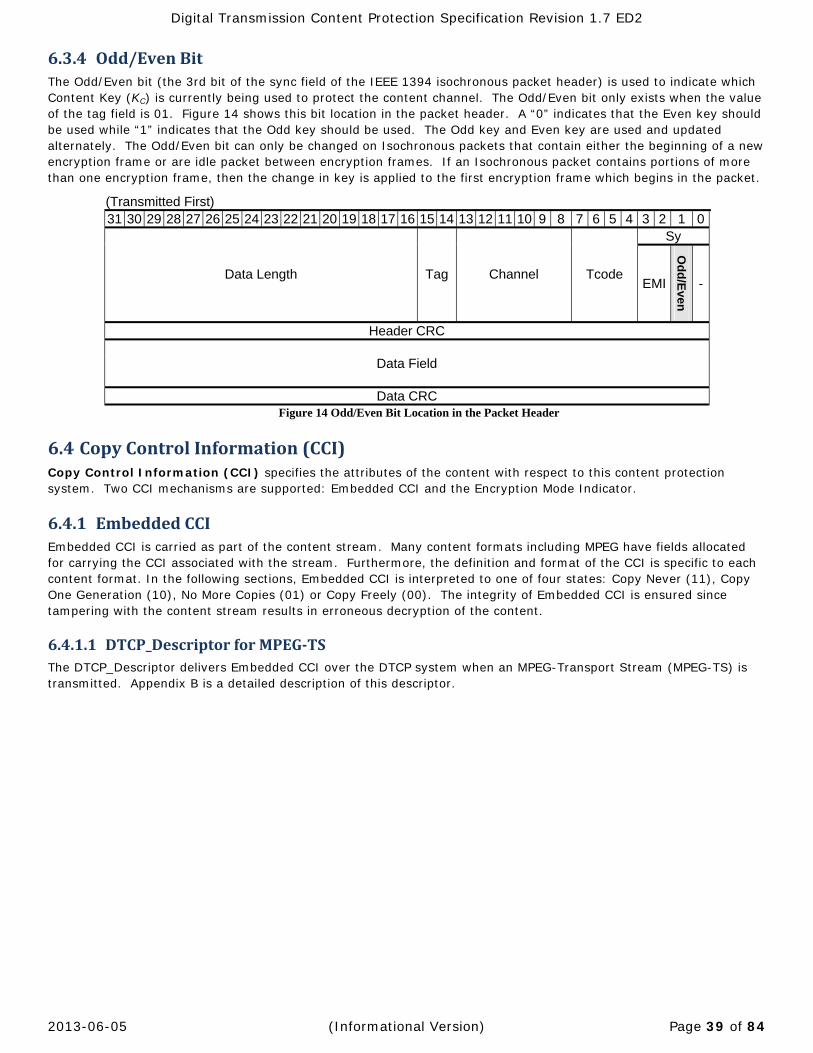
Digital Transmission Content Protection Specification Revision 1.7 ED2
2013-06-05 (Informational Version) Page 39 of 84
6.3.4 Odd/EvenBitThe Odd/Even bit (the 3rd bit of the sync field of the IEEE 1394 isochronous packet header) is used to indicate which Content Key (KC) is currently being used to protect the content channel. The Odd/Even bit only exists when the value of the tag field is 01. Figure 14 shows this bit location in the packet header. A “0” indicates that the Even key should be used while “1” indicates that the Odd key should be used. The Odd key and Even key are used and updated alternately. The Odd/Even bit can only be changed on Isochronous packets that contain either the beginning of a new encryption frame or are idle packet between encryption frames. If an Isochronous packet contains portions of more than one encryption frame, then the change in key is applied to the first encryption frame which begins in the packet.
(Transmitted First) 31 30 29 28 27 26 25 24 23 22 21 20 19 18 17 16 15 14 13 12 11 10 9 8 7 6 5 4 3 2 1 0
Data Length Tag Channel Tcode
Sy
EMI
Od
d/E
ven
-
Header CRC
Data Field
Data CRC Figure 14 Odd/Even Bit Location in the Packet Header
6.4 CopyControlInformation(CCI)Copy Control Information (CCI) specifies the attributes of the content with respect to this content protection system. Two CCI mechanisms are supported: Embedded CCI and the Encryption Mode Indicator.
6.4.1 EmbeddedCCIEmbedded CCI is carried as part of the content stream. Many content formats including MPEG have fields allocated for carrying the CCI associated with the stream. Furthermore, the definition and format of the CCI is specific to each content format. In the following sections, Embedded CCI is interpreted to one of four states: Copy Never (11), Copy One Generation (10), No More Copies (01) or Copy Freely (00). The integrity of Embedded CCI is ensured since tampering with the content stream results in erroneous decryption of the content.
6.4.1.1 DTCP_DescriptorforMPEG‐TSThe DTCP_Descriptor delivers Embedded CCI over the DTCP system when an MPEG-Transport Stream (MPEG-TS) is transmitted. Appendix B is a detailed description of this descriptor.

Digital Transmission Content Protection Specification Revision 1.7 ED2
2013-06-05 (Informational Version) Page 40 of 84
6.4.1.2 ContentManagementInformation(CMI)The CMI Field is the means to carry usage rules independent of content transmission format. The AKE command used to transmit CMI is defined in Section Error! Reference source not found. and the format of CMI Field is defined in Appendix E.
6.4.2 EncryptionModeIndicator(EMI)The Encryption Mode Indicator (EMI) provides an easy-to-access yet secure mechanism for indicating the CCI associated with a stream of digital content. For IEEE 1394 serial buses, the EMI is placed in the most significant two bits of the Sync field of packet header as shown in Figure 15. The EMI bits only exist when the value of the tag field is 01. By locating the EMI in an easy-to-access location, devices can immediately determine the CCI of the content stream without needing to decode the content transport format to extract the Embedded CCI. This ability is critical for enabling bit-stream recording devices (e.g., digital VCR) that do not recognize and cannot decode specific content formats.
The EMI bits can only be changed on isochronous packets that contain either the beginning of a new encryption frame or are idle packets between encryption frames. If an Isochronous packet contains portions of more than one encryption frame, then the change in EMI is applied to the first encryption frame which begins in the packet.
(Transmitted First) 31 30 29 28 27 26 25 24 23 22 21 20 19 18 17 16 15 14 13 12 11 10 9 8 7 6 5 4 3 2 1 0
Data Length Tag Channel Tcode
sy
EMI
Odd/E
ven
-
Header CRC
Data Field
Data CRC Figure 15 EMI Location
The EMI indicates the mode of encryption applied to a stream:
Licensed source devices will choose the right encryption mode according to the characteristics of the content stream and set its EMI accordingly. If the content stream consists of multiple substreams with different Embedded CCI, the strictest Embedded CCI will be used to set the EMI.
Licensed sink devices will choose the right decryption mode as indicated by the EMI.
If the EMI bits are tampered with, the encryption and decryption modes will not match, resulting in an erroneous decryption of the content.

Digital Transmission Content Protection Specification Revision 1.7 ED2
2013-06-05 (Informational Version) Page 41 of 84
The following table shows the encoding used for the EMI bits.
EMI Mode EMI Value Meaning Authentication Required Mode A 11 Copy-never8
Full
Mode B 10 Copy-one-generation Restricted or Full Copy-count Full
Mode C 01 No-more-copies Restricted or Full N.A.9
00 Copy-free None, not encrypted Table 8 EMI Encoding
An encoding of 00 is used to indicate that the content can be copied-freely. No authentication or encryption is required to protect this content.
For content that is never to be copied (e.g., content from prerecorded media with a Copy Generation Management System (CGMS) value of 11), an EMI encoding of 11 is used. This content can only be exchanged between devices that have successfully completed the Full Authentication procedure.
An EMI encoding of 10 indicates that one generation of copies or limited number of copies (Copy-count) can be made (e.g. content from prerecorded media with a CGMS value of 10). Devices exchanging Copy-one-generation content can either use Full or Restricted Authentication. Copy-count content can only be exchanged between devices that have successfully completed the Full Authentication procedure.
If Copy-one-generation content with EMI = 10 is copied, unless otherwise noted future exchanges across a digital interconnect are marked with an EMI encoding of 01, which indicates that a single-generation copy has already been made.
6.4.3 RelationshipbetweenEmbeddedCCIandEMIA protected stream of content may consist of one or more programs. Each of these programs may be assigned a different level of Embedded CCI. Since EMI is associated with the overall stream of content it is possible that the stream will be composed of multiple programs and that the EMI will not match the Embedded CCI value of each of the protected programs. In the event that there is a conflict, the most restrictive Embedded CCI value will be used for the EMI. Table 7 The following table shows the allowable combinations of EMI and Embedded CCI:
EMI Embedded CCI for each program 00
01 10 11 EPN10-not-asserted EPN10-asserted
Mode A Allowed Allowed Allowed11 Allowed Allowed Mode B Allowed Allowed Prohibited Allowed ProhibitedMode C Allowed Allowed Allowed Allowed ProhibitedN.A. Allowed Prohibited Prohibited Prohibited Prohibited
Table 9 Relationship between EMI and Embedded CCI
8 In case of audio transmission (refer to 6.4.5), the meaning of Mode A depends on each AM824 application type as defined in Appendix A.
9 Not Applicable. No EMI mode is defined for an encoding of 00.
10 Definition and usage of EPN is specified in Appendix B.
11 Not typically used.

Digital Transmission Content Protection Specification Revision 1.7 ED2
2013-06-05 (Informational Version) Page 42 of 84
6.4.4 TreatmentofEMI/EmbeddedCCIforAudiovisualDeviceFunctionsThis section presents the behavior of audiovisual device functions according to their ability to send/receive EMI and detect/modify Embedded CCI. Other functions not listed in this section may be permitted as long as they are consistent with the provisions of this specification.
6.4.4.1 Format‐cognizantsourcefunctionA Format-cognizant source function can recognize the Embedded CCI of a content stream being transmitted. Table 8 The following table shows the EMI that should be used for a transmitted content stream containing component programs with the following Embedded CCI values:
Embedded CCI of programs EMI
00 01 10 11 EPN10-not-asserted
EPN10-asserted
Don’t care Don’t care *12 Don’t care Present Mode A
Don’t care Don’t care Cannot be Present
Present Cannot be Present
Mode B Don’t care Present
Cannot be Present
Don’t care Cannot be Present
Don’t care Don’t care Present Cannot be Present13
Cannot be Present
Mode C
Present Cannot be Present
Cannot be Present
Cannot be Present
Cannot be Present
N.A.
Other combinations Transmission Prohibited
Table 10 Format-Cognizant Source Function CCI handling
6.4.4.2 Format‐non‐cognizantsourcefunctionA Format-non-cognizant source function need not recognize the Embedded CCI of a content stream being transmitted. Table 9 The following table shows the EMI value that is used by a Format-non-cognizant source function when transmitting content streams with the following EMI:
EMI or recorded CCI14 of source content EMI used for transmission
Copy-never Mode A Copy-one-generation Mode B No-more-copies Mode C Copy-free N.A.
Table 11 Format-Non-Cognizant Source Function CCI handling
12 Don’t care, but not typically used.
13 This combination is allowed for format-non-cognizant source function, but is not permitted for format-cognizant source functions.
14 Recorded CCI is copy control information that is not embedded in the content program and does not require knowledge of the content format to extract.

Digital Transmission Content Protection Specification Revision 1.7 ED2
2013-06-05 (Informational Version) Page 43 of 84
6.4.4.3 Format‐cognizantrecordingfunctionA Format-cognizant recording function recognizes the Embedded CCI of a received content program prior to writing it to recordable media. Table 10 The following table shows the CCI value that is recorded with content programs marked with specific Embedded CCI values.
EMI Embedded CCI of program 00 01 10 11
Mode A Recordable Do not record *15 Do not record
Mode B Recordable Discard entire content stream16
*15 Discard entire content stream16
Mode C Recordable Do not record Do not record
Discard entire content stream16
Table 12 Format-cognizant recording function CCI handling
6.4.4.4 Format‐cognizantsinkfunctionA Format-cognizant sink function can recognize the Embedded CCI of received content. Table 11 The following table shows the Embedded CCI of programs contained within the content stream that can be received.
EMI Embedded CCI of program 00 01 10 11
Mode A Available for processing
Available for processing17
Available for processing
Available for processing
Mode B Available for processing
Discard entire content stream18
Available for processing
Discard entire content stream18
Mode C Available for processing
Available for processing
Available for processing19
Discard entire content stream18
Table 13 Format-cognizant sink function CCI handling
6.4.4.5 Format‐non‐cognizantrecordingfunctionA Format-non-cognizant recording function can record content with appropriate EMI onto recordable media. Table 12 The following table shows the EMI value for content that can be recorded and the CCI that should be recorded with the content.
EMI of the received stream
Recorded CCI20 to be written onto user recordable media
Mode A (Copy-never) Stream cannot be recorded Mode B (Copy-one-generation) No-more-copies Mode C (No-more-copies) Stream cannot be recorded
Table 14 Format-non-cognizant recording function CCI handling
6.4.4.6 Format‐non‐cognizantsinkfunctionFor this function, which does not recognize the Embedded CCI, the content must be treated in a manner consistent with its EMI. For example, treatment that does not depend on Embedded CCI is possible.
15 If the recording function supports recording a CCI value of No-more-copies then the CCI value of No-more-copies shall be recorded with the program. Otherwise the CCI of Copy-never shall be recorded with the program.
16 If the function detects this CCI combination among the programs it is recording, the entire content stream is discarded.
17 Not typically used.
18 If the function detects this CCI combination among the programs, the entire content stream is discarded.
19 If the device has a rule for handling No-more-copies, this program shall be handled according to the rule. Otherwise the program shall be handled as Copy Never.
20 Recorded CCI is copy control information that is not embedded in the content program and does not require knowledge of the content format to extract.
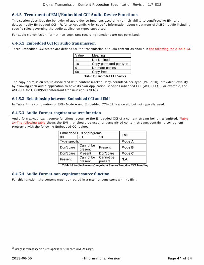
Digital Transmission Content Protection Specification Revision 1.7 ED2
2013-06-05 (Informational Version) Page 44 of 84
6.4.5 TreatmentofEMI/EmbeddedCCIAudioDeviceFunctionsThis section describes the behavior of audio device functions according to their ability to send/receive EMI and detect/modify Embedded CCI. Refer to Appendix A for specific information about treatment of AM824 audio including specific rules governing the audio application types supported.
For audio transmission, format non-cognizant recording functions are not permitted.
6.4.5.1 EmbeddedCCIforaudiotransmissionThree Embedded CCI states are defined for the transmission of audio content as shown in the following tableTable 13.
Value Meaning 11 Not Defined 10 Copy-permitted-per-type 01 No-more-copies 00 Copy-free
Table 15 Embedded CCI Values
The copy permission status associated with content marked Copy-permitted-per-type (Value 10) provides flexibility by allowing each audio application to have its own Application Specific Embedded CCI (ASE-CCI). For example, the ASE-CCI for IEC60958 conformant transmission is SCMS.
6.4.5.2 RelationshipbetweenEmbeddedCCIandEMIIn Table 7 the combination of EMI=Mode A and Embedded CCI=01 is allowed, but not typically used.
6.4.5.3 Audio‐Format‐cognizantsourcefunctionAudio-format-cognizant source functions recognize the Embedded CCI of a content stream being transmitted. Table 14 The following table shows the EMI that should be used for transmitted content streams containing component programs with the following Embedded CCI values.
Embedded CCI of programs EMI
00 01 10 Type specific21 Mode A
Don't care Cannot be present
Present Mode B
Don't care Present Don't care Mode C
Present Cannot be present
Cannot be present
N.A.
Table 16 Audio-Format-Congnizant Source Function CCI handling
6.4.5.4 Audio‐Format‐non‐cognizantsourcefunctionFor this function, the content must be treated in a manner consistent with its EMI.
21 Usage is format specific, see Appendix A for each AM824 usage.

Digital Transmission Content Protection Specification Revision 1.7 ED2
2013-06-05 (Informational Version) Page 45 of 84
6.4.5.5 Audio‐Format‐cognizantrecordingfunctionAudio-Format-cognizant recording functions recognizes the Embedded CCI of a received content program prior to writing it to recordable media. Table 15 The following table shows the CCI handling rules for each EMI Mode.
EMI Embedded CCI of program 00 01 10
Mode A Recordable Do not record Recordable22 Mode B Recordable Discard entire content stream23 Recordable22 Mode C Recordable Do not record Recordable22
Table 17 Audio-Format-cognizant recording function CCI handling
6.4.5.6 Audio‐Format‐cognizantsinkfunctionAudio-format-cognizant sink functions can recognize the Embedded CCI of received content. Table 16 The following table shows the Embedded CCI of programs contained within the content stream that can be received.
EMI Embedded CCI of program 00 01 10
Mode A Available for processing Available for processing Available for processingMode B Available for processing Discard entire content stream24 Available for processingMode C Available for processing Available for processing Available for processing
Table 18 Audio-format-cognizant sink function CCI handling
6.4.5.7 Audio‐Format‐non‐cognizantrecordingfunctionAudio-Format-non-cognizant recording function is not permitted.
6.4.5.8 Audio‐Format‐non‐cognizantsinkfunctionAudio-Format-non-cognizant sink functions shall behave as described in Section 6.4.4.6.
6.5 CommonDeviceCategoriesDevices may support zero or more of the functions described in Section 6.4.4.
Common types of fixed function devices include, but are not limited to:
1. Format-cognizant pre-recorded content source device has a format-cognizant source function. (e.g., DVD player)
2. Format-cognizant real-time-delivery content source/decoding device has a format-cognizant source function and format-cognizant sink function. (e.g., Set Top Box or Digital TV).
3. Format-cognizant recorder and player has a format-cognizant source function, format-cognizant sink function, and format-cognizant recording function. (e.g., DV-VCR)
4. Format-non-cognizant recorder and player has a format-non-cognizant source function and format-non-cognizant recording function. (e.g., D-VHS VCR)
5. Format-non-cognizant Bus Bridge has a format-non-cognizant source function and format-non-cognizant sink function. (e.g., IEEE 1394 to IEEE 1394 bus bridge)
22 The CCI value of No-more-copies shall be recorded with the program. Additional rules for recording are specified by each audio application in the Appendix A.
23 If the function detects this CCI combination among the programs it is recording, the entire content stream is discarded.
24 If the function detects this CCI combination among the programs it is recording, the entire content stream is discarded.

Digital Transmission Content Protection Specification Revision 1.7 ED2
2013-06-05 (Informational Version) Page 46 of 84
6.6 ContentChannelCiphersAll compliant devices support the baseline cipher and possibly additional, optional ciphers25 for protecting content.
6.6.1 BaselineCipherAll devices and applications must, at a minimum, support the baseline cipher to ensure interoperability. The M6 block cipher using the converted cipher-block-chaining (C-CBC) mode is the baseline cipher. This cipher is described in detail in DTCP Specification available under license from DTLA.
6.6.2 OptionalCipher(NOTESTABLISHED2)Support is defined in Chapter 4 (Device Capability Mask), Chapter 6 (Establishment of multiple KX values), Chapter 8 (Encoding of cipher selection in the AV/C Digital Interface Command Set).
For optional content channel ciphers, Extended Full authentication is mandatory and therefore the other Authentication procedures (Full, Restricted and Enhanced Restricted) are not used.
6.6.2.1 AES‐128CipherFor AES-128 as an optional cipher, the Cipher Block Chaining (CBC) mode is used. AES-128 is described in FIPS 197 dated November 26, 2001 and the CBC mode is described in NIST SP800-38A 2001 Edition.
Additional rules for AES-128 Cipher are described in the DTCP Specification available under license from DTLA.
25 NOT ESTABLISHED see section 1.10
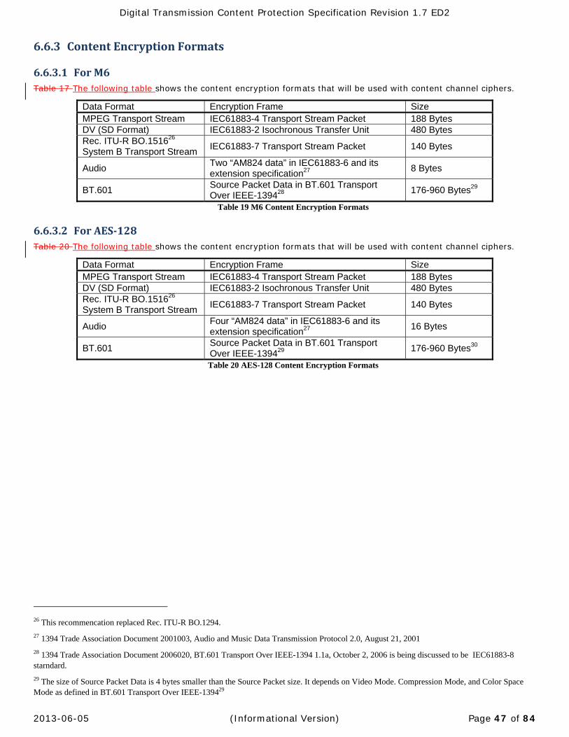
Digital Transmission Content Protection Specification Revision 1.7 ED2
2013-06-05 (Informational Version) Page 47 of 84
6.6.3 ContentEncryptionFormats
6.6.3.1 ForM6Table 17 The following table shows the content encryption formats that will be used with content channel ciphers.
Data Format Encryption Frame Size MPEG Transport Stream IEC61883-4 Transport Stream Packet 188 Bytes DV (SD Format) IEC61883-2 Isochronous Transfer Unit 480 Bytes Rec. ITU-R BO.151626 System B Transport Stream
IEC61883-7 Transport Stream Packet 140 Bytes
Audio Two “AM824 data” in IEC61883-6 and its extension specification27
8 Bytes
BT.601 Source Packet Data in BT.601 Transport Over IEEE-139428
176-960 Bytes29
Table 19 M6 Content Encryption Formats
6.6.3.2 ForAES‐128Table 20 The following table shows the content encryption formats that will be used with content channel ciphers.
Data Format Encryption Frame Size MPEG Transport Stream IEC61883-4 Transport Stream Packet 188 Bytes DV (SD Format) IEC61883-2 Isochronous Transfer Unit 480 Bytes Rec. ITU-R BO.151626 System B Transport Stream
IEC61883-7 Transport Stream Packet 140 Bytes
Audio Four “AM824 data” in IEC61883-6 and its extension specification27
16 Bytes
BT.601 Source Packet Data in BT.601 Transport Over IEEE-139429
176-960 Bytes30
Table 20 AES-128 Content Encryption Formats
26 This recommencation replaced Rec. ITU-R BO.1294.
27 1394 Trade Association Document 2001003, Audio and Music Data Transmission Protocol 2.0, August 21, 2001
28 1394 Trade Association Document 2006020, BT.601 Transport Over IEEE-1394 1.1a, October 2, 2006 is being discussed to be IEC61883-8 starndard.
29 The size of Source Packet Data is 4 bytes smaller than the Source Packet size. It depends on Video Mode. Compression Mode, and Color Space Mode as defined in BT.601 Transport Over IEEE-139429
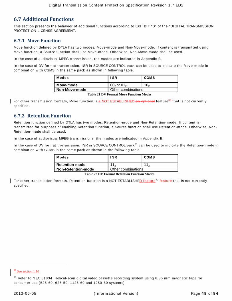
Digital Transmission Content Protection Specification Revision 1.7 ED2
2013-06-05 (Informational Version) Page 48 of 84
6.7 AdditionalFunctionsThis section presents the behavior of additional functions according to EXHIBIT “B” of the “DIGITAL TRANSMISSION PROTECTION LICENSE AGREEMENT.
6.7.1 MoveFunctionMove function defined by DTLA has two modes, Move-mode and Non-Move-mode. If content is transmitted using Move function, a Source function shall use Move-mode. Otherwise, Non-Move-mode shall be used.
In the case of audiovisual MPEG transmission, the modes are indicated in Appendix B.
In the case of DV format transmission, ISR in SOURCE CONTROL pack can be used to indicate the Move-mode in combination with CGMS in the same pack as shown in following table.
Modes ISR CGMS
Move-mode 002 or 012 102 Non-Move-mode Other combinations
Table 21 DV Format Move Function Modes
For other transmission formats, Move function is a NOT ESTABLISHED an optional feature30 that is not currently specified.
6.7.2 RetentionFunctionRetention function defined by DTLA has two modes, Retention-mode and Non-Retention-mode. If content is transmitted for purposes of enabling Retention function, a Source function shall use Retention-mode. Otherwise, Non-Retention-mode shall be used.
In the case of audiovisual MPEG transmissions, the modes are indicated in Appendix B.
In the case of DV format transmission, ISR in SOURCE CONTROL pack31 can be used to indicate the Retention-mode in combination with CGMS in the same pack as shown in the following table.
Modes ISR CGMS
Retention-mode 112 112 Non-Retention-mode Other combinations
Table 22 DV Format Retention Function Modes
For other transmission formats, Retention function is a NOT ESTABLISHED feature30 feature that is not currently specified.
30 See section 1.10
31 Refer to "IEC 61834 Helical-scan digital video cassette recording system using 6,35 mm magnetic tape for consumer use (525-60, 625-50, 1125-60 and 1250-50 systems)
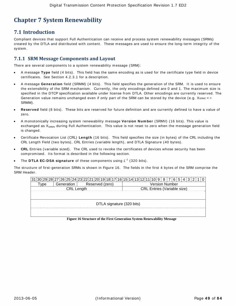
Digital Transmission Content Protection Specification Revision 1.7 ED2
2013-06-05 (Informational Version) Page 49 of 84
Chapter7 SystemRenewability
7.1 IntroductionCompliant devices that support Full Authentication can receive and process system renewability messages (SRMs) created by the DTLA and distributed with content. These messages are used to ensure the long-term integrity of the system.
7.1.1 SRMMessageComponentsandLayoutThere are several components to a system renewability message (SRM):
A message Type field (4 bits). This field has the same encoding as is used for the certificate type field in device certificates. See Section 4.2.3.1 for a description.
A message Generation field (SRMM) (4 bits). This field specifies the generation of the SRM. It is used to ensure the extensibility of the SRM mechanism. Currently, the only encodings defined are 0 and 1. The maximum size is specified in the DTCP specification available under license from DTLA. Other encodings are currently reserved. The Generation value remains unchanged even if only part of the SRM can be stored by the device (e.g. XSRMC <= SRMM).
Reserved field (8 bits). These bits are reserved for future definition and are currently defined to have a value of zero.
A monotonically increasing system renewability message Version Number (SRMV) (16 bits). This value is exchanged as XSRMV during Full Authentication. This value is not reset to zero when the message generation field is changed.
Certificate Revocation List (CRL) Length (16 bits). This field specifies the size (in bytes) of the CRL including the CRL Length Field (two bytes), CRL Entries (variable length), and DTLA Signature (40 bytes).
CRL Entries (variable sized). The CRL used to revoke the certificates of devices whose security has been compromised. Its format is described in the following section.
The DTLA EC-DSA signature of these components using L-1 (320 bits).
The structure of first-generation SRMs is shown in Figure 16. The fields in the first 4 bytes of the SRM comprise the SRM Header.
31 30 29 28 27 26 25 24 23 22 21 20 19 18 17 16 15 14 13 12 11 10 9 8 7 6 5 4 3 2 1 0Type Generation Reserved (zero) Version Number
CRL Length CRL Entries (Variable size)
DTLA signature (320 bits)
Figure 16 Structure of the First Generation System Renewability Message
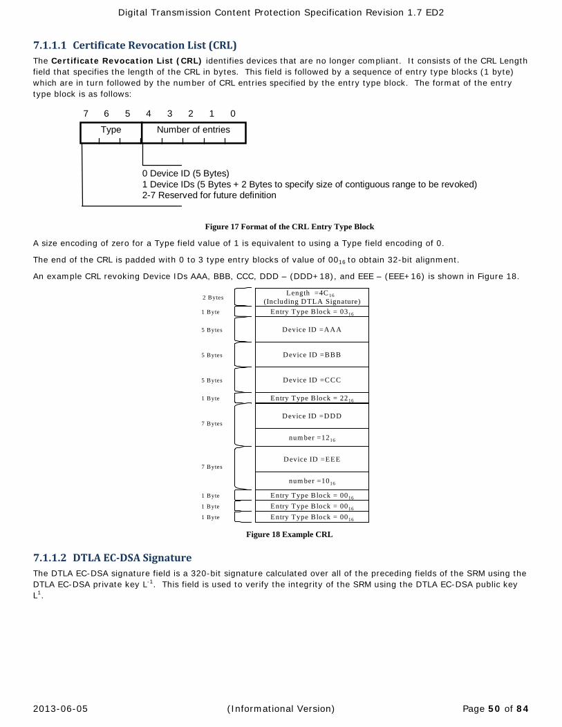
Digital Transmission Content Protection Specification Revision 1.7 ED2
2013-06-05 (Informational Version) Page 50 of 84
7.1.1.1 CertificateRevocationList(CRL)The Certificate Revocation List (CRL) identifies devices that are no longer compliant. It consists of the CRL Length field that specifies the length of the CRL in bytes. This field is followed by a sequence of entry type blocks (1 byte) which are in turn followed by the number of CRL entries specified by the entry type block. The format of the entry type block is as follows:
0 Device ID (5 Bytes)1 Device IDs (5 Bytes + 2 Bytes to specify size of contiguous range to be revoked)2-7 Reserved for future definition
1 0235 467
Number of entriesType
Figure 17 Format of the CRL Entry Type Block
A size encoding of zero for a Type field value of 1 is equivalent to using a Type field encoding of 0.
The end of the CRL is padded with 0 to 3 type entry blocks of value of 0016 to obtain 32-bit alignment.
An example CRL revoking Device IDs AAA, BBB, CCC, DDD – (DDD+18), and EEE – (EEE+16) is shown in Figure 18.
Figure 18 Example CRL
7.1.1.2 DTLAEC‐DSASignatureThe DTLA EC-DSA signature field is a 320-bit signature calculated over all of the preceding fields of the SRM using the DTLA EC-DSA private key L-1. This field is used to verify the integrity of the SRM using the DTLA EC-DSA public key L1.
Entry Type Block = 0316
Device ID =AAA
Device ID =BBB
Device ID =CCC
Entry Type Block = 2216
Device ID =DDD
num ber =1216
Device ID =EEE
num ber =1016
1 Byte
1 Byte
5 Bytes
5 Bytes
5 Bytes
7 Bytes
7 Bytes
Length =4C 16 (Including DTLA Signature)
Entry Type Block = 00161 Byte
Entry Type Block = 0016 1 Byte
Entry Type Block = 00161 Byte
2 Bytes
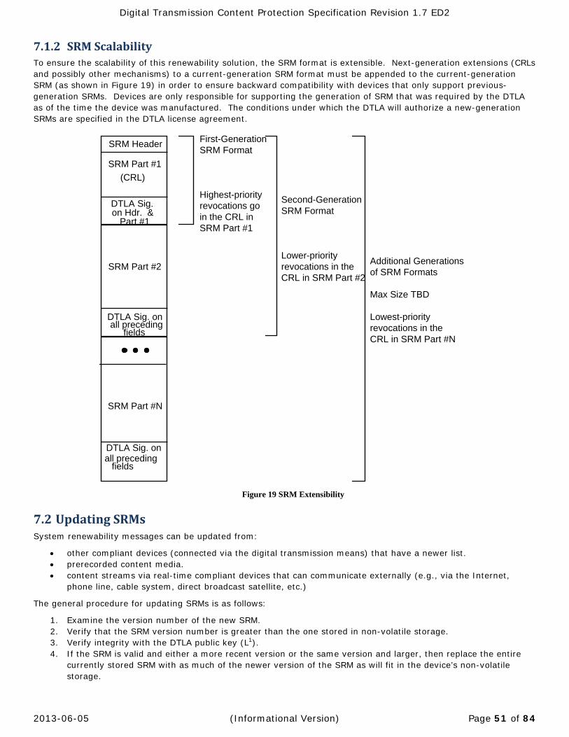
Digital Transmission Content Protection Specification Revision 1.7 ED2
2013-06-05 (Informational Version) Page 51 of 84
7.1.2 SRMScalabilityTo ensure the scalability of this renewability solution, the SRM format is extensible. Next-generation extensions (CRLs and possibly other mechanisms) to a current-generation SRM format must be appended to the current-generation SRM (as shown in Figure 19) in order to ensure backward compatibility with devices that only support previous-generation SRMs. Devices are only responsible for supporting the generation of SRM that was required by the DTLA as of the time the device was manufactured. The conditions under which the DTLA will authorize a new-generation SRMs are specified in the DTLA license agreement.
DTLA Sig.on Hdr. &
Part #1
SRM Part #1
(CRL)
DTLA Sig. onall preceding
fields
SRM Part #2
SRM Part #N
DTLA Sig. onall preceding
fields
SRM Header
Additional Generationsof SRM Formats
Max Size TBD
Lowest-priority revocations in theCRL in SRM Part #N
First-GenerationSRM Format
Highest-priorityrevocations goin the CRL inSRM Part #1
Second-GenerationSRM Format
Lower-priority revocations in theCRL in SRM Part #2
Figure 19 SRM Extensibility
7.2 UpdatingSRMsSystem renewability messages can be updated from:
other compliant devices (connected via the digital transmission means) that have a newer list. prerecorded content media. content streams via real-time compliant devices that can communicate externally (e.g., via the Internet,
phone line, cable system, direct broadcast satellite, etc.)
The general procedure for updating SRMs is as follows:
1. Examine the version number of the new SRM. 2. Verify that the SRM version number is greater than the one stored in non-volatile storage. 3. Verify integrity with the DTLA public key (L1). 4. If the SRM is valid and either a more recent version or the same version and larger, then replace the entire
currently stored SRM with as much of the newer version of the SRM as will fit in the device’s non-volatile storage.
Digital Transmission Content Protection Specification Revision 1.7 ED2
2013-06-05 (Informational Version) Page 52 of 84
7.2.1 Device‐to‐DeviceUpdateandStateMachines
7.2.1.1 UpdatingaDevice’sSRMfromAnotherCompliantDeviceDuring the Full Authentication procedure, if a more recent (or more complete) system renewability message is discovered on another device, the following procedure is used to update the device with the outdated and/or less complete copy:
1. The device with the newer and/or more complete SRM sends it to the other device.
2. The device being updated verifies the candidate SRM’s signature with the DTLA’s public key.
3. If the signature is valid, the device being updated replaces the entire currently stored SRM in its non-volatile storage with as much of the replacement message as will fit in its non-volatile storage.
This procedure should take place following the completion of the exchange of KX.
A detailed description of the System Renewability protocol and associated state machine can be found in the DTCP Specification available under license from the DTLA.
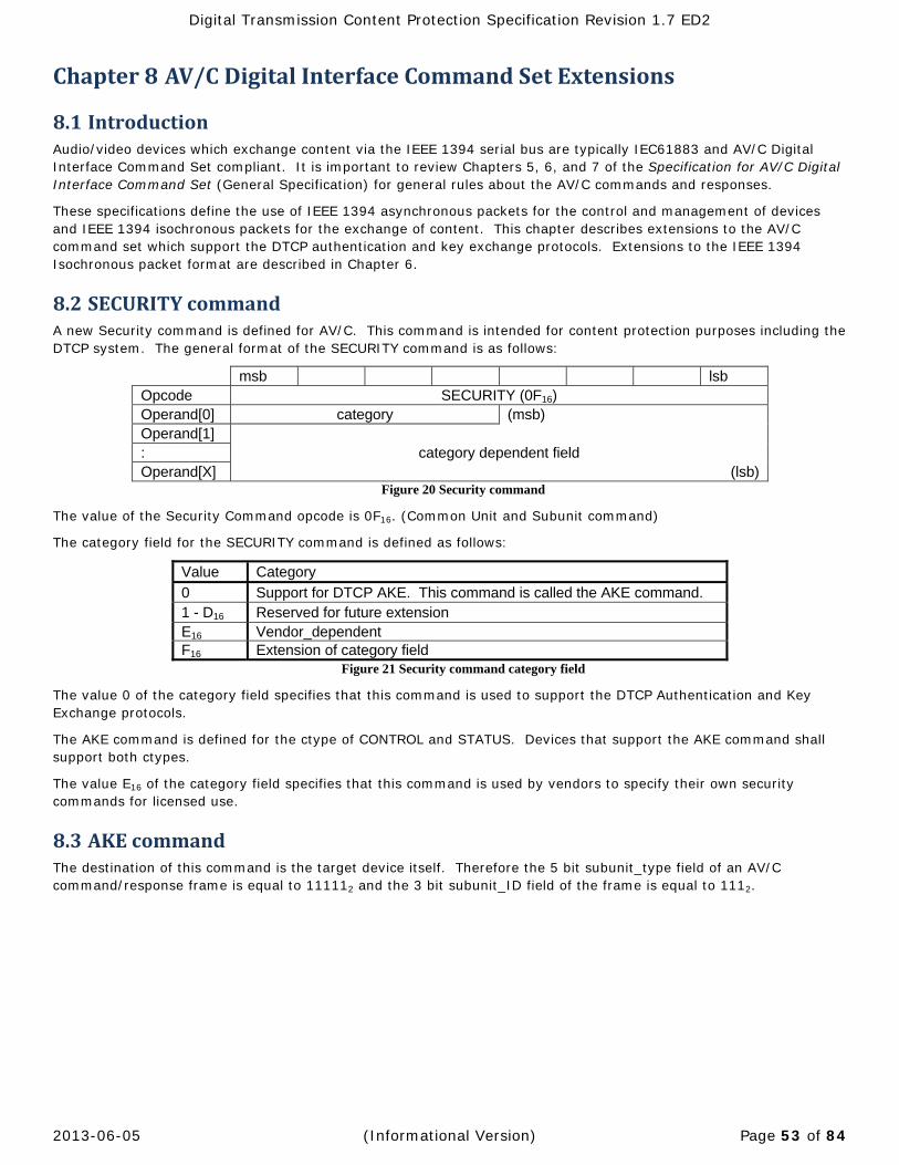
Digital Transmission Content Protection Specification Revision 1.7 ED2
2013-06-05 (Informational Version) Page 53 of 84
Chapter8 AV/CDigitalInterfaceCommandSetExtensions
8.1 IntroductionAudio/video devices which exchange content via the IEEE 1394 serial bus are typically IEC61883 and AV/C Digital Interface Command Set compliant. It is important to review Chapters 5, 6, and 7 of the Specification for AV/C Digital Interface Command Set (General Specification) for general rules about the AV/C commands and responses.
These specifications define the use of IEEE 1394 asynchronous packets for the control and management of devices and IEEE 1394 isochronous packets for the exchange of content. This chapter describes extensions to the AV/C command set which support the DTCP authentication and key exchange protocols. Extensions to the IEEE 1394 Isochronous packet format are described in Chapter 6.
8.2 SECURITYcommandA new Security command is defined for AV/C. This command is intended for content protection purposes including the DTCP system. The general format of the SECURITY command is as follows:
msb lsb Opcode SECURITY (0F16) Operand[0] category (msb) Operand[1] : category dependent field Operand[X] (lsb)
Figure 20 Security command
The value of the Security Command opcode is 0F16. (Common Unit and Subunit command)
The category field for the SECURITY command is defined as follows:
Value Category
0 Support for DTCP AKE. This command is called the AKE command. 1 - D16 Reserved for future extension E16 Vendor_dependent F16 Extension of category field
Figure 21 Security command category field
The value 0 of the category field specifies that this command is used to support the DTCP Authentication and Key Exchange protocols.
The AKE command is defined for the ctype of CONTROL and STATUS. Devices that support the AKE command shall support both ctypes. The value E16 of the category field specifies that this command is used by vendors to specify their own security commands for licensed use.
8.3 AKEcommandThe destination of this command is the target device itself. Therefore the 5 bit subunit_type field of an AV/C command/response frame is equal to 111112 and the 3 bit subunit_ID field of the frame is equal to 1112.
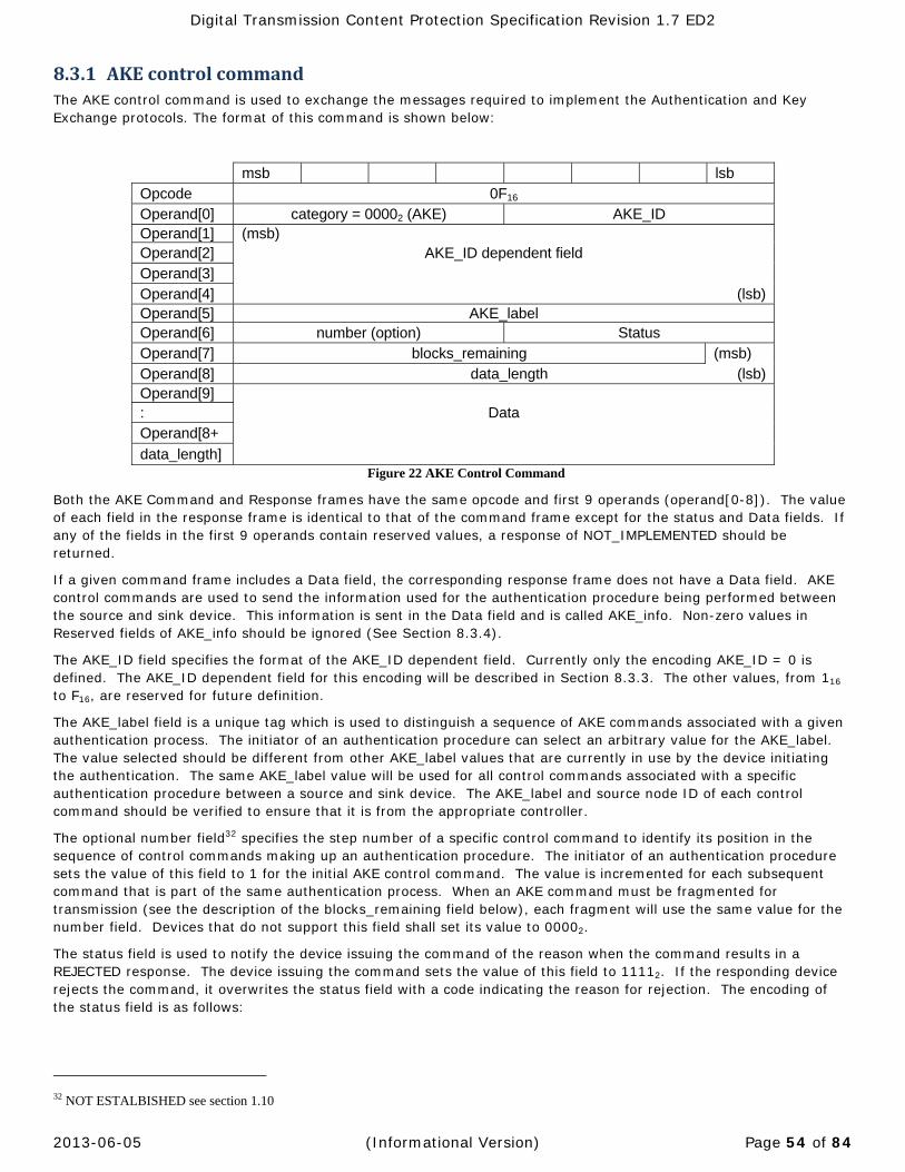
Digital Transmission Content Protection Specification Revision 1.7 ED2
2013-06-05 (Informational Version) Page 54 of 84
8.3.1 AKEcontrolcommandThe AKE control command is used to exchange the messages required to implement the Authentication and Key Exchange protocols. The format of this command is shown below:
msb lsb Opcode 0F16 Operand[0] category = 00002 (AKE) AKE_ID Operand[1] (msb) Operand[2] AKE_ID dependent field Operand[3] Operand[4] (lsb)Operand[5] AKE_label Operand[6] number (option) Status Operand[7] blocks_remaining (msb) Operand[8] data_length (lsb)Operand[9] : Data Operand[8+
data_length] Figure 22 AKE Control Command
Both the AKE Command and Response frames have the same opcode and first 9 operands (operand[0-8]). The value of each field in the response frame is identical to that of the command frame except for the status and Data fields. If any of the fields in the first 9 operands contain reserved values, a response of NOT_IMPLEMENTED should be returned.
If a given command frame includes a Data field, the corresponding response frame does not have a Data field. AKE control commands are used to send the information used for the authentication procedure being performed between the source and sink device. This information is sent in the Data field and is called AKE_info. Non-zero values in Reserved fields of AKE_info should be ignored (See Section 8.3.4).
The AKE_ID field specifies the format of the AKE_ID dependent field. Currently only the encoding AKE_ID = 0 is defined. The AKE_ID dependent field for this encoding will be described in Section 8.3.3. The other values, from 116 to F16, are reserved for future definition.
The AKE_label field is a unique tag which is used to distinguish a sequence of AKE commands associated with a given authentication process. The initiator of an authentication procedure can select an arbitrary value for the AKE_label. The value selected should be different from other AKE_label values that are currently in use by the device initiating the authentication. The same AKE_label value will be used for all control commands associated with a specific authentication procedure between a source and sink device. The AKE_label and source node ID of each control command should be verified to ensure that it is from the appropriate controller.
The optional number field32 specifies the step number of a specific control command to identify its position in the sequence of control commands making up an authentication procedure. The initiator of an authentication procedure sets the value of this field to 1 for the initial AKE control command. The value is incremented for each subsequent command that is part of the same authentication process. When an AKE command must be fragmented for transmission (see the description of the blocks_remaining field below), each fragment will use the same value for the number field. Devices that do not support this field shall set its value to 00002.
The status field is used to notify the device issuing the command of the reason when the command results in a REJECTED response. The device issuing the command sets the value of this field to 11112. If the responding device rejects the command, it overwrites the status field with a code indicating the reason for rejection. The encoding of the status field is as follows:
32 NOT ESTALBISHED see section 1.10
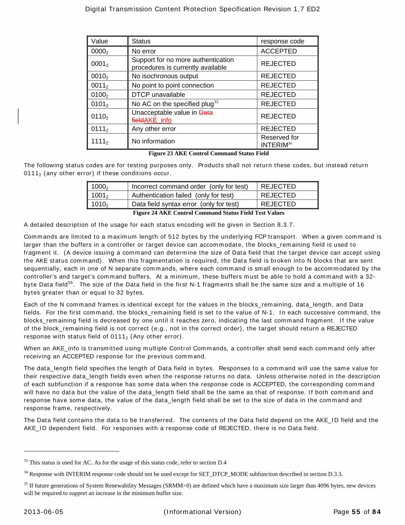
Digital Transmission Content Protection Specification Revision 1.7 ED2
2013-06-05 (Informational Version) Page 55 of 84
Value Status response code
00002 No error ACCEPTED
00012 Support for no more authentication procedures is currently available
REJECTED
00102 No isochronous output REJECTED
00112 No point to point connection REJECTED 01002 DTCP unavailable REJECTED 01012 No AC on the specified plug33 REJECTED
01102 Unacceptable value in Data fieldAKE_info
REJECTED
01112 Any other error REJECTED
11112 No information Reserved for INTERIM34
Figure 23 AKE Control Command Status Field
The following status codes are for testing purposes only. Products shall not return these codes, but instead return 01112 (any other error) if these conditions occur.
10002 Incorrect command order (only for test) REJECTED 10012 Authentication failed (only for test) REJECTED 10102 Data field syntax error (only for test) REJECTED
Figure 24 AKE Control Command Status Field Test Values
A detailed description of the usage for each status encoding will be given in Section 8.3.7.
Commands are limited to a maximum length of 512 bytes by the underlying FCP transport. When a given command is larger than the buffers in a controller or target device can accommodate, the blocks_remaining field is used to fragment it. (A device issuing a command can determine the size of Data field that the target device can accept using the AKE status command). When this fragmentation is required, the Data field is broken into N blocks that are sent sequentially, each in one of N separate commands, where each command is small enough to be accommodated by the controller’s and target’s command buffers. At a minimum, these buffers must be able to hold a command with a 32-byte Data field35. The size of the Data field in the first N-1 fragments shall be the same size and a multiple of 16 bytes greater than or equal to 32 bytes.
Each of the N command frames is identical except for the values in the blocks_remaining, data_length, and Data fields. For the first command, the blocks_remaining field is set to the value of N-1. In each successive command, the blocks_remaining field is decreased by one until it reaches zero, indicating the last command fragment. If the value of the block_remaining field is not correct (e.g., not in the correct order), the target should return a REJECTED response with status field of 01112 (Any other error).
When an AKE_info is transmitted using multiple Control Commands, a controller shall send each command only after receiving an ACCEPTED response for the previous command.
The data_length field specifies the length of Data field in bytes. Responses to a command will use the same value for their respective data_length fields even when the response returns no data. Unless otherwise noted in the description of each subfunction if a response has some data when the response code is ACCEPTED, the corresponding command will have no data but the value of the data_length field shall be the same as that of response. If both command and response have some data, the value of the data_length field shall be set to the size of data in the command and response frame, respectively.
The Data field contains the data to be transferred. The contents of the Data field depend on the AKE_ID field and the AKE_ID dependent field. For responses with a response code of REJECTED, there is no Data field.
33 This status is used for AC. As for the usage of this status code, refer to section D.4
34 Response with INTERIM response code should not be used except for SET_DTCP_MODE subfunction described in section D.3.3.
35 If future generations of System Renewability Messages (SRMM>0) are defined which have a maximum size larger than 4096 bytes, new devices will be required to support an increase in the minimum buffer size.

Digital Transmission Content Protection Specification Revision 1.7 ED2
2013-06-05 (Informational Version) Page 56 of 84
8.3.2 AKEstatuscommandThe format of the AKE status command is as follows:
msb Lsb Opcode 0F16 Operand[0] category = 00002 (AKE) AKE_ID Operand[1] (msb) Operand[2] AKE_ID dependent field Operand[3] Operand[4] (lsb)Operand[5] FF16 Operand[6] F16 Status Operand[7] 7F16 (msb) Operand[8] data_length (lsb)
Figure 25 AKE Status Command
Both the Command and Response frames have the same structure. The values of each field of the command and response frames are identical except for the AKE_ID dependent, status, and data_length fields.
The AKE_ID field specifies the format of the AKE_ID dependent field. The AKE_ID dependent field for this encoding will be described in Section 8.3.3. Currently, only the encoding of AKE_ID=0 is defined. The other values, from 116 to F16, are reserved for future definition.
The status field is used by a device to query the state of another device. When the command is issued, the value of this field is set to 11112. In the response, the target device overwrites this field with a value indicating its current situation.
Value Status Response code
00002 No error STABLE
00012 Support for no more authentication procedures is currently available
STABLE
00102 No isochronous output STABLE
00112 No point to point connection STABLE 01002 DTCP unavailable STABLE 01112 Any other error STABLE
11112 No information36 REJECTED Figure 26 AKE Status Command Status Field
The following status codes are for testing purposes only. Products shall not return these codes, but instead return 01112 (any other error) if these conditions occur.
10012 Authentication failed (only for test) STABLE Figure 27 AKE Status Command Status Field Test Values
A detailed description of the usage for each status encoding will be described in Section 8.3.7.
The data_length field specifies the target device’s maximum Data field capacity in bytes. When the status command is issued, the value of this field is set to 1FF16. In the response, the target device overwrites this field with a value indicating its current situation. The minimum value to be supported is 02016 (32 bytes).
36 It is recommended that implementers not use the “No information” response.

Digital Transmission Content Protection Specification Revision 1.7 ED2
2013-06-05 (Informational Version) Page 57 of 84
8.3.3 AKE_IDdependentfield(AKE_ID=0)When AKE_ID = 0, the format of the AKE_ID dependent field is as follows:
msb lsb Operand[1] Subfunction Operand[2] AKE_procedure Operand[3] exchange_key Operand[4] subfunction_dependent
Figure 28 AKE_ID dependent field
The subfunction field specifies the operation of control commands. The most significant bit of the subfunction field indicates whether the control command has data or not.
If the msb is 0, that command has some data and the data_length field indicates its length. If the msb is 1, that command has no data and the data_length field indicates the length of the Data field in
response frame whose response code is ACCEPTED.
The subfunctions are described in the DTCP Specification available under license from DTLA. The following table lists currently defined subfunctions:
Value Subfunction Comments
0116 CHALLENGE Send random value. This subfunction when sent from a sink device initiates the AKE procedure.
0216 RESPONSE Return data computed with the received random value.
0316 EXCHANGE_KEY Send an encrypted Exchange Key (KX) to the authenticated contents-sink device.
0416 SRM Send SRM to a device that has an outdated or smaller SRM.
0516 RESPONSE2 Return data computed with the received random value and a unique value used to identify the sink device.
0616 SET_CMI Send CMI Field to make Content Key (KC, AKC)
C016 AKE_CANCEL Notify a device that the current authentication procedure cannot be continued.
8016 CONTENT_KEY_REQ Request the data required for making Content Key (KC).
8116 SET_DTCP_MODE Set DTCP mode: This subfunction is used for AC. Refer to Appendix D.
8216 CAPABILITY_REQ Used to determine the capability of the device. 8316 CMI_REQ Request the data required for making Content Key (KC, AKC) 8416 CONTENT_KEY_REQ2 Confirm the requested Session Exchange Key is available or not 8516 CAPABILITY_REQ2 Used to inform and determine the capability of the device
Table 23 AKE Subfunctions
For status commands, the value of the subfunction field shall be set to FF16.

Digital Transmission Content Protection Specification Revision 1.7 ED2
2013-06-05 (Informational Version) Page 58 of 84
Each bit of the AKE_procedure field corresponds to one type of authentication procedure, as described in the table below.
Bit AKE_procedure
0 (lsb) Restricted Authentication procedure (rest_auth) 1 Enhanced Restricted Authentication procedure (en_rest_auth)37 2 Full Authentication procedure (full_auth) 3 Extended Full Authentication procedure38 (ex_full_auth, NOT ESTABLISHED2) 4 - 7 (msb) Reserved for future extension and shall be zero
Table 24 AKE_procedure values
For the control command, the initiator of an authentication procedure sets one bit in this field to specify which type of authentication will be performed. The value of the field then remains constant through the rest of that authentication procedure.
For the status command the initiator shall set the initial value of this field to FF16. The target will overwrite the field, clearing the bits that indicate the authentication procedures that the target does not support as a source device. For example, if a source device supports both Full Authentication and Enhanced Restricted Authentication, the values of the AKE_procedure field would be set to 0616.
Sink devices should investigate which authentication procedures a source device supports using the status command prior to starting the authentication protocol. The following table shows how to select the appropriate authentication procedure:
Source supported Authentication Procedures
Sink supported authentication procedures
Rest_auth and En_rest_auth
Rest_auth and Full_auth
Rest_auth, Full_auth and Ex_full_auth
Rest_auth Restricted Authentication Restricted Authentication
Restricted Authentication
En_rest_auth and Full_auth
Enhanced Restricted Authentication
Full Authentication Full Authentication
En_rest_auth, Full_auth and Ex_full_auth
Enhanced Restricted Authentication
Full Authentication Extended Full Authentication
Table 25 Authentication selection
37 Source devices that support the Full Authentication procedure shall verify the device certificate of the sink device and examine the SRM even in Restricted Authentication. This authentication procedure is referred to as Enhanced Restricted Authentication in this chapter.
38 Devices that support extended device certificates use the Extended Full Authentication procedure described in this chapter.

Digital Transmission Content Protection Specification Revision 1.7 ED2
2013-06-05 (Informational Version) Page 59 of 84
Each bit of the exchange_key field corresponds to one (or more) key(s) as described in the table below:
Bit Exchange_key
0 (lsb) Exchange Key for M6 Copy-never content (requires Full or Extended Full Authentication)
1 Exchange Key for M6 Copy-one-generation content (any authentication acceptable)
2 Exchange Key for M6 No-more-copies content (any authentication acceptable)
3 Exchange key for AES-128 (requires Extended Full Authentication) 4 Reserved for future extension and shall be zero 5 Session Exchange Key 6 – 7 (msb) Reserved for future extension and shall be zero
Table 26 Exchange_key values
For the control command, the sink device sets the value of this field at the start of an authentication procedure to specify which Exchange Key(s) will be supplied by the source device after the successful completion of the procedure. For Full Authentication any bit can be set for M6. For Restricted Authentication, only one bit for Copy-one-generation or No-more-copies shall be set. This field remains constant for the remainder of the authentication procedure except when the EXCHANGE_KEY subfunction is performed.
For the status command, the initiator shall set FF16 in this field, and target shall clear every bit of the field that corresponds to an Exchange Key that the target cannot supply.
Session Exchange Key is available only when the value of Bit 5 is set to one.
For example, if target can supply three keys that correspond to bit0 through bit2 in the table above, the value of the exchange_key field will be set to 0716.
A sink device should decide which key(s) it will require by getting this information in advance of the authentication procedure with the status command.
The definition of the subfunction_dependent field varies. The DTCP Specification available under license from the DTLA describes the definitions for control commands. For status commands the value of this field is set to FF16 for both the command and response frames.
8.4 BusResetBehaviorIf the source device continues to transmit content on an isochronous channel following a bus reset, the same Exchange Keys and Content Keys shall be used as were in use prior to the reset.
If a bus reset occurs during an authentication procedure, both the source and sink devices shall immediately stop the authentication procedure. Following the reset, the Source Node ID (SID) field in the CIP header may have changed requiring the sink device to restart the authentication procedure using the new SID.
8.5 ActionwhenUnauthorizedDeviceisDetectedDuringAuthenticationAfter returning an ACCEPTED response to an initiator of a command, the target examines the AKE_information. If the target determines that the initiator is an unauthorized device then the target shall immediately stop the AKE procedure without any notification.
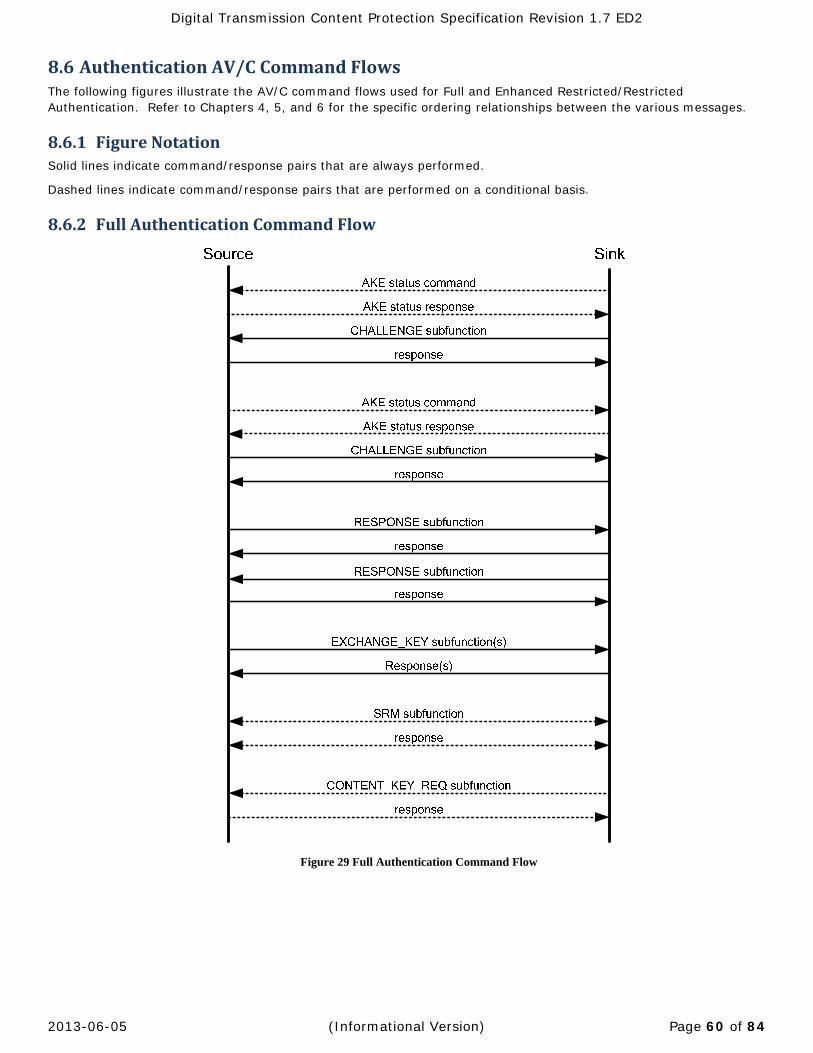
Digital Transmission Content Protection Specification Revision 1.7 ED2
2013-06-05 (Informational Version) Page 60 of 84
8.6 AuthenticationAV/CCommandFlowsThe following figures illustrate the AV/C command flows used for Full and Enhanced Restricted/Restricted Authentication. Refer to Chapters 4, 5, and 6 for the specific ordering relationships between the various messages.
8.6.1 FigureNotationSolid lines indicate command/response pairs that are always performed.
Dashed lines indicate command/response pairs that are performed on a conditional basis.
8.6.2 FullAuthenticationCommandFlow
Figure 29 Full Authentication Command Flow
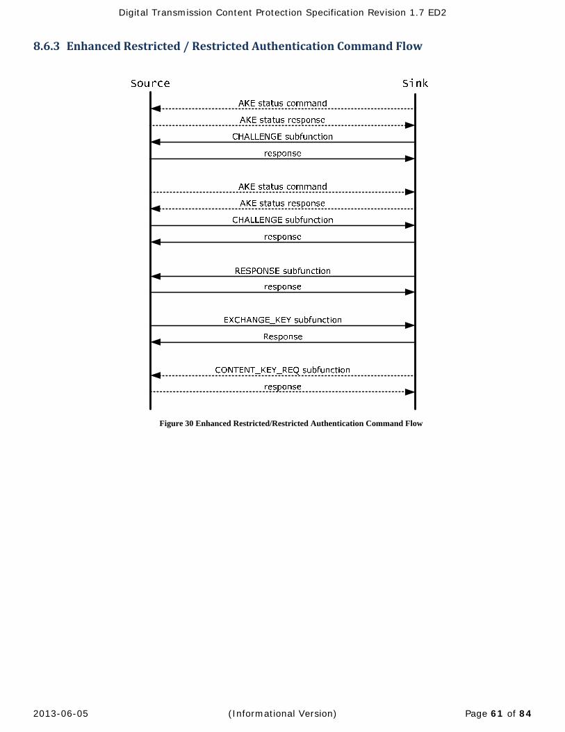
Digital Transmission Content Protection Specification Revision 1.7 ED2
2013-06-05 (Informational Version) Page 61 of 84
8.6.3 EnhancedRestricted/RestrictedAuthenticationCommandFlow
Figure 30 Enhanced Restricted/Restricted Authentication Command Flow

Digital Transmission Content Protection Specification Revision 1.7 ED2
2013-06-05 (Informational Version) Page 62 of 84
AppendixA AdditionalRulesforAudioApplicationsOnly AM824 is specified for audio transport, other formats are to be specified.
A.1 AM824AudioThis section describes the behavior of AM824 audio device functions according to their ability to send/receive EMI and detect/modify Embedded CCI. AM824 is an audio content format that is transmitted according to the IEC61883-6 specification39 and its extension specification40.
For AM824 audio transmission, devices supporting DTCP shall distinguish between application types by detecting the LABEL value.41
For AM824 audio transmission, the combination of EMI=mode A and Embedded CCI=01 is permitted and may be used. Mode A is used for content that requires System Renewability as described in Chapter 7.
A.1.1 Type1:IEC60958ConformantAudio
A.1.1.1 DefinitionIEC 60958 conformant audio applications have a LABEL value of 0016-3F16. IEC61937 data can also be transmitted using Type 1.
A.1.1.2 RelationshipbetweenASE‐CCIandEmbeddedCCIThis application type utilizes three values of Embedded CCI: Copy-free, Copy-permitted-per-type, and No-more-copies. SCMS states are used as the ASE-CCI. The mappings between SCMS states as specified by IEC60958 are mapped to the Embedded CCI values as shown in following table.
SCMS State Embedded CCI Value Recordable (Copy free) 00 (Copy-free) General 00 (Copy-free) Recordable, set L bit to “Home copy” (Copy once) 10 (Copy-permitted-per-type) Not recordable (Copy prohibited) 01 (No-more-copies)
Table 27 Relationships between SCMS State and Embedded CCI
A.1.1.3 UsageofModeA(EMI=11)The usage of Mode A for this application type is not currently specified.
39 Consumer Audio/Video Equipment -Digital Interface - Part 6: Audio and music data transmission protocol.
40 1394 Trade Association Document 2001003, Audio and Music Data Transmission Protocol 2.0, August 21, 2001.
41 LABEL value is defined by the IEC61883-6 specification and its extension specification.
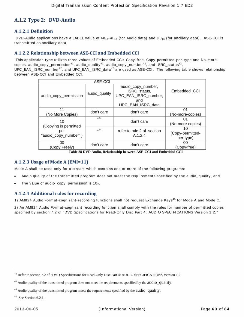
Digital Transmission Content Protection Specification Revision 1.7 ED2
2013-06-05 (Informational Version) Page 63 of 84
A.1.2 Type2: DVD‐Audio
A.1.2.1 Definition DVD-Audio applications have a LABEL value of 4816-4F16 (for Audio data) and D016 (for ancillary data). ASE-CCI is transmitted as ancillary data.
A.1.2.2 RelationshipbetweenASE‐CCIandEmbeddedCCI This application type utilizes three values of Embedded CCI: Copy-free, Copy-permitted-per-type and No-more-copies. audio_copy_permission42, audio_quality42, audio_copy_number42, and ISRC_status42, UPC_EAN_ISRC_number42, and UPC_EAN_ISRC_data42 are used as ASE-CCI. The following table shows relationship between ASE-CCI and Embedded CCI.
ASE-CCI
Embedded CCI audio_copy_permission
audio_quality
audio_copy_number, ISRC_status,
UPC_EAN_ISRC_number, and
UPC_EAN_ISRC_data 11
(No More Copies) don’t care don’t care
01 (No-more-copies)
10 (Copying is permitted
per “audio_copy_number” )
*43
don’t care 01
(No-more-copies)
*44
refer to rule 2 of section A.1.2.4
10 (Copy-permitted-
per-type) 00
(Copy Freely) don’t care don’t care
00 (Copy-free)
Table 28 DVD Audio, Relationship between ASE-CCI and Embedded CCI
A.1.2.3 UsageofModeA(EMI=11)Mode A shall be used only for a stream which contains one or more of the following programs:
Audio quality of the transmitted program does not meet the requirements specified by the audio_quality, and
The value of audio_copy_permission is 102.
A.1.2.4 Additionalrulesforrecording1) AM824 Audio Format-cognizant-recording functions shall not request Exchange Keys45 for Mode A and Mode C.
2) An AM824 Audio Format-cognizant recording function shall comply with the rules for number of permitted copies specified by section 7.2 of “DVD Specifications for Read-Only Disc Part 4: AUDIO SPECIFICATIONS Version 1.2.”
42 Refer to section 7.2 of “DVD Specifications for Read-Only Disc Part 4: AUDIO SPECIFICATIONS Version 1.2.
43 Audio quality of the transmitted program does not meet the requirements specified by the audio_quality.
44 Audio quality of the transmitted program meets the requirements specified by the audio_quality.
45 See Section 6.2.1.

Digital Transmission Content Protection Specification Revision 1.7 ED2
2013-06-05 (Informational Version) Page 64 of 84
A.1.3 Type3:SuperAudioCD
A.1.3.1 DefinitionThe Super Audio CD audio application has a LABEL value of 5016, 5116 and/or 5816 (for audio data) and D116 (for ancillary data). Application specific embedded CCI is transmitted as ancillary data.
A.1.3.2 RelationshipbetweenASE‐CCIandEmbeddedCCIThis application type utilizes one value of Embedded CCI: No-more-copies and both Track_Attribute46 and Track _Copy_Management46 are used as ASE-CCI in this revision of this specification. The following table shows relationship between ASE-CCI and Embedded CCI.
ASE-CCI Embedded CCI
Track_Attribute Track_Copy_Management00002 All 0 01 (No-more-copies)
Other combinations *47 Table 29 Super Audio CD, Relationship between ASE-CCI and Embedded CCI
A.1.3.3 UsageofModeA(EMI=11)For a stream, that contains one or more of the following programs. Mode A shall be used:
The value of Track_Attribute 00002 and Track_Copy_Management is all 0.
Other combinations of Track_Attribute and Track_Copy_Management values in this revision of this specification. They are reserved for future enhancement. This provision is subject to revision.
A.2 MPEGAudioAudio Transmission via MPEG Transport Stream is a NOT ESTABLISHED feature2 that is not currently specified.
46 Refer to the Super Audio CD System Description Version 1.2 Part 3.
47 These combinations are reserved for future enhancement and the associated Embedded CCI shall be regarded as “No-more-copies” for this revision of this specification. This provision is subject to revision.
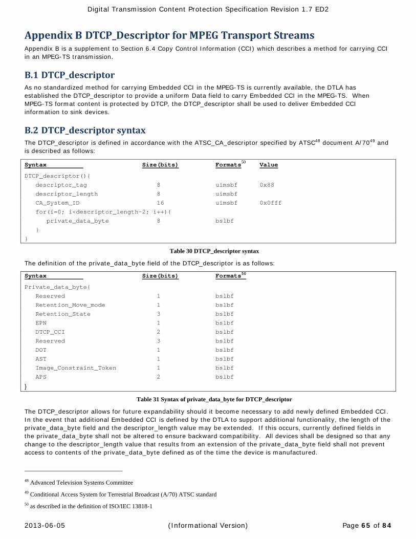
Digital Transmission Content Protection Specification Revision 1.7 ED2
2013-06-05 (Informational Version) Page 65 of 84
AppendixB DTCP_DescriptorforMPEGTransportStreamsAppendix B is a supplement to Section 6.4 Copy Control Information (CCI) which describes a method for carrying CCI in an MPEG-TS transmission.
B.1 DTCP_descriptorAs no standardized method for carrying Embedded CCI in the MPEG-TS is currently available, the DTLA has established the DTCP_descriptor to provide a uniform Data field to carry Embedded CCI in the MPEG-TS. When MPEG-TS format content is protected by DTCP, the DTCP_descriptor shall be used to deliver Embedded CCI information to sink devices.
B.2 DTCP_descriptorsyntaxThe DTCP_descriptor is defined in accordance with the ATSC_CA_descriptor specified by ATSC48 document A/7049 and is described as follows:
Syntax Size(bits) Formats50 Value
DTCP_descriptor(){
descriptor_tag 8 uimsbf 0x88
descriptor_length 8 uimsbf
CA_System_ID 16 uimsbf 0x0fff
for(i=0; i<descriptor_length-2; i++){
private_data_byte 8 bslbf
}
}
Table 30 DTCP_descriptor syntax
The definition of the private_data_byte field of the DTCP_descriptor is as follows:
Syntax Size(bits) Formats50
Private_data_byte{
Reserved 1 bslbf
Retention_Move_mode 1 bslbf
Retention_State 3 bslbf
EPN 1 bslbf
DTCP_CCI 2 bslbf
Reserved 3 bslbf
DOT 1 bslbf
AST 1 bslbf
Image_Constraint_Token 1 bslbf
APS 2 bslbf
}
Table 31 Syntax of private_data_byte for DTCP_descriptor
The DTCP_descriptor allows for future expandability should it become necessary to add newly defined Embedded CCI. In the event that additional Embedded CCI is defined by the DTLA to support additional functionality, the length of the private_data_byte field and the descriptor_length value may be extended. If this occurs, currently defined fields in the private_data_byte shall not be altered to ensure backward compatibility. All devices shall be designed so that any change to the descriptor_length value that results from an extension of the private_data_byte field shall not prevent access to contents of the private_data_byte defined as of the time the device is manufactured.
48 Advanced Television Systems Committee
49 Conditional Access System for Terrestrial Broadcast (A/70) ATSC standard
50 as described in the definition of ISO/IEC 13818-1

Digital Transmission Content Protection Specification Revision 1.7 ED2
2013-06-05 (Informational Version) Page 66 of 84
B.2.1 private_data_byteDefinitions:Retention_Move_mode
This field is used to indicate the mode of the Move function or the Retention function in combination with the DTCP_CCI as shown in following tables.
Modes Retention_Move_mode DTCP_CCI Move-mode 02 102 Non-Move-mode Other combinations
Table 32 Move Function Modes
Modes Retention_Move_mode DTCP_CCI Retention-mode 02 112 Non-Retention-mode Other combinations
Table 33 Retention Function Modes
Retention_State51,52
This field indicates the value of the Retention_State.
Retention_State_Indicator Retention Time 0002 Forever 0012 1 week 0102 2 days 0112 1 day 1002 12 hours 1012 6 hours 1102 3 hours 1112 90 minutes
Table 34 Retention States
Encryption Plus Non-assertion (EPN)51
This field indicates the value of the EPN.
EPN Meaning
02 EPN-asserted
12 EPN-unasserted
Table 35 EPN
51 Definition and usage are specified in EXHIBIT “B” of the “DIGITAL TRANSMISSION PROTECTION LICENSE AGREEMENT”
52 If an inter-industry standard or consensus supports retention states that differ from those set forth in this Specification, then this Specification may be amended or supplemented to reflect such consensus retention states.
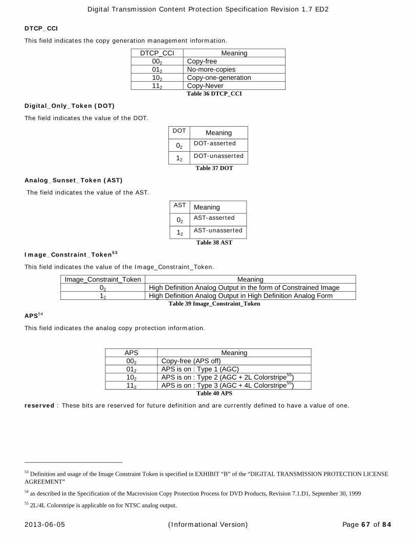
Digital Transmission Content Protection Specification Revision 1.7 ED2
2013-06-05 (Informational Version) Page 67 of 84
DTCP_CCI
This field indicates the copy generation management information.
DTCP_CCI Meaning 002 Copy-free 012 No-more-copies 102 Copy-one-generation 112 Copy-Never
Table 36 DTCP_CCI
Digital_Only_Token (DOT)
The field indicates the value of the DOT.
DOT Meaning
02 DOT-asserted
12 DOT-unasserted
Table 37 DOT
Analog_Sunset_Token (AST)
The field indicates the value of the AST.
AST Meaning
02 AST-asserted
12 AST-unasserted
Table 38 AST
Image_Constraint_Token53
This field indicates the value of the Image_Constraint_Token.
Image_Constraint_Token Meaning 02 High Definition Analog Output in the form of Constrained Image 12 High Definition Analog Output in High Definition Analog Form
Table 39 Image_Constraint_Token
APS54
This field indicates the analog copy protection information.
APS Meaning 002 Copy-free (APS off) 012 APS is on : Type 1 (AGC) 102 APS is on : Type 2 (AGC + 2L Colorstripe55) 112 APS is on : Type 3 (AGC + 4L Colorstripe55)
Table 40 APS
reserved : These bits are reserved for future definition and are currently defined to have a value of one.
53 Definition and usage of the Image Constraint Token is specified in EXHIBIT “B” of the “DIGITAL TRANSMISSION PROTECTION LICENSE AGREEMENT”
54 as described in the Specification of the Macrovision Copy Protection Process for DVD Products, Revision 7.1.D1, September 30, 1999
55 2L/4L Colorstripe is applicable on for NTSC analog output.
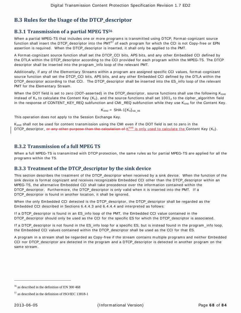
Digital Transmission Content Protection Specification Revision 1.7 ED2
2013-06-05 (Informational Version) Page 68 of 84
B.3 RulesfortheUsageoftheDTCP_descriptor
B.3.1 TransmissionofapartialMPEGTS56When a partial MPEG-TS that includes one or more programs is transmitted using DTCP, Format-cognizant source function shall insert the DTCP_descriptor into the PMT57 of each program for which the CCI is not Copy-free or EPN assertion is required. When the DTCP_descriptor is inserted, it shall only be applied to the PMT.
A Format-cognizant source function shall set the DTCP_CCI bits, APS bits, and any other Embedded CCI defined by the DTLA within the DTCP_descriptor according to the CCI provided for each program within the MPEG-TS. The DTCP descriptor shall be inserted into the program_info loop of the relevant PMT.
Additionally, if any of the Elementary Streams within a program are assigned specific CCI values, format-cognizant source function shall set the DTCP_CCI bits, APS bits, and any other Embedded CCI defined by the DTLA within the DTCP_descriptor according to that CCI. The DTCP_descriptor shall be inserted into the ES_info loop of the relevant PMT for the Elementary Stream.
When the DOT field is set to zero (DOT-asserted) in the DTCP_descriptor, source functions shall use the following KXH0 instead of KX to calculate the Content Key (KC), and the source functions shall set 10012 to the cipher_algorithm field in the response of CONTENT_KEY_REQ subfunction and CMI_REQ subfunction while they use KXH0 for the Content Key.
KXH0 = SHA-1[KX]lsb_96
This operation does not apply to the Session Exchange Key.
KXH0 shall not be used for content transmission using the CMI even if the DOT field is set to zero in the DTCP_descriptor. or any other purpose than the calculation of KXH0 is only used to calculate the Content Key (KC).
B.3.2 TransmissionofafullMPEGTSWhen a full MPEG-TS is transmitted with DTCP protection, the same rules as for partial MPEG-TS are applied for all the programs within the TS.
B.3.3 TreatmentoftheDTCP_descriptorbythesinkdeviceThis section describes the treatment of the DTCP_descriptor when received by a sink device. When the function of the sink device is format cognizant and receives recognizable Embedded CCI other than the DTCP_descriptor within an MPEG-TS, the alternative Embedded CCI shall take precedence over the information contained within the DTCP_descriptor. Furthermore, the DTCP_descriptor is only valid when it is inserted into the PMT. If a DTCP_descriptor is found in another location, it shall be ignored.
When the only Embedded CCI detected is the DTCP_descriptor, the DTCP_descriptor shall be regarded as the Embedded CCI described in Sections 6.4.4.3 and 6.4.4.4 and interpreted as follows:
If a DTCP_descriptor is found in an ES_info loop of the PMT, the Embedded CCI value contained in the DTCP_descriptor should only be used as the CCI for the specific ES for which the DTCP_descriptor is associated.
If a DTCP_descriptor is not found in the ES_info loop for a specific ES, but is instead found in the program_info loop, the Embedded CCI values contained within the DTCP_descriptor shall be used as the CCI for that ES.
A program in a stream shall be regarded as Copy-free if the stream contains multiple programs and neither Embedded CCI nor DTCP_descriptor are detected in the program and a DTCP_descriptor is detected in another program on the same stream.
56 as described in the definition of EN 300 468
57 as described in the definition of ISO/IEC 13818-1

Digital Transmission Content Protection Specification Revision 1.7 ED2
2013-06-05 (Informational Version) Page 69 of 84
AppendixC LimitationoftheNumberofSinkDevicesReceivingaContentStream
Without exception, the number of authenticated sink devices, including those connected via bus bridge devices receiving content from a Full Authentication capable source device shall be limited to no more than 34 devices at any time.
C.1 LimitationMechanisminSourceDeviceA source device that has a Full Authentication capability shall count the number of sink device using a Sink Counter. The source device shall increment the Sink Counter and register the Device ID after successful AKE58 with an unregistered sink device where the sink’s device certificate has an AP flag value of zero. The source device shall also increment the Sink Counter after successful AKE regardless of its registration status, when the sink’s device certificate has an AP flag value of one. If the source device outputs content to different buses separately, it shall count the number of the sink devices using one Sink Counter.
When the source device expires all Exchange Keys (KX, see section 6.3.1) and Session Exchange Keys (KS) (see section 6.3.2), it shall reset the Sink Counter to zero and clear the list of registered Device IDs. When the source device expires all Exchange Keys (KX) and Session Exchange Keys (KS) distributed to certain sink device(s), it may decrement the Sink Counter by the number of the sink device(s) and clear registered Device ID(s) of the sink device(s) from the list. When the source device expires all Exchange Keys (KX) and Session Exchange Keys (KS) distributed to certain bridge device(s), it may decrement the Sink Counter by the number of successful AKE with the bridge device(s). Except for these cases, a source device shall not decrease nor reset its Sink Counter.
When the Sink Counter reaches the prescribed maximum limit of 34, the source device shall reject any further authentication requests from both unregistered sink devices with a device certificate having an AP flag value of zero and sink devices with a device certificate having an AP flag value of one with the status code of 01112 “Any other error”. This status code should not be used for other commands to indicate that the Sink Counter is 34.
58 Successful AKE means after source device sends Exchange Keys (KX or KS).

Digital Transmission Content Protection Specification Revision 1.7 ED2
2013-06-05 (Informational Version) Page 70 of 84
Figure 31 Sink Counter Algorithm (Informative)
When a source device that has CIH flag value of one receives RESPONSE2 subfunction with NB flag value of one, it shall use IDU instead of Device ID and regard the value of the AP flag as zero for the above described procedure.

Digital Transmission Content Protection Specification Revision 1.7 ED2
2013-06-05 (Informational Version) Page 71 of 84
C.2 LimitationMechanisminDTCPBusBridgeDeviceThe DTCP bus bridge device has transcrypting capability which uses a sink function and a source function where the sink function decrypts the received content stream from upstream source(s) and the source function re-encrypts the stream and sends it to downstream sink(s). A DTCP bus bridge device shall have Full Authentication capability and have a device certificate with the AP flag value of one. The bridge performs authentication with the upstream source as a proxy of downstream sink(s).
C.2.1 DTCPBusBridgeDeviceSourceFunctionA DTCP bus bridge device shall count the number of authenticated downstream sink devices receiving the content stream from an upstream source device using a Sink Counter. The bus bridge device’s Exchange Keys (KX) or Session Exchange Keys are those used by its source function.
The bridge device shall increment the Sink Counter and register Device ID after successful AKE with an unregistered downstream sink device with a device certificate having an AP flag value of zero. The bridge device shall also increment the Sink Counter after successful AKE with a downstream sink device, regardless of its registration status, where the downstream sink's device certificate has an AP flag value of one.
The bridge device shall reject the authentication request from both unregistered downstream sink devices having an AP flag of zero and downstream sink devices having an AP flag of one with the status code of 01112 "Any other error", when the Sink Counter in the bridge device is equal to the prescribed maximum limit of 34. This status code should not be used for other commands to indicate that the Sink Counter is 34. The bridge device may reject further authentication request from unregistered downstream sink device having an AP flag of zero or a downstream sink device having an AP flag of one with the status code of 01112 "Any other error", when it judges a Sink Counter of an upstream source device is 34.
When a DTCP bus bridge device expires all Exchange Keys (KX) and Session Exchange Keys, it shall reset its Sink Counter to zero and clear the list of registered Device IDs. When the source device expires all Exchange Keys (KX) and Session Exchange Keys distributed to certain sink device(s), it may decrement the Sink Counter by the number of the sink device(s) and clear registered Device ID(s) of the sink device(s) from the list. When the source device expires all Exchange Keys (KX) and Session Exchange Keys distributed to certain bridge device(s), it may decrement the Sink Counter by the number of successful AKE with the bridge device(s). Except for this case, a bridge device shall not decrease nor reset its Sink Counter. The bridge device shall not expire its Exchange Key while it outputs any stream.
If a DTCP bus bridge device outputs the content to different buses separately, it shall count the number of the sink device using one Sink Counter.
If a DTCP bus bridge device outputs different content streams to different buses separately, e.g. via two transcrypting capability in a DTCP bus bridge device, the bridge device shall count the number of downstream sink devices using one Sink Counter, as long as the same Exchange Key is used for all of the downstream buses.
When a DTCP bus bridge device that has CIH flag value of one receives RESPONSE2 subfunction with NB flag value of one, it shall use IDU instead of Device ID and regard the value of the AP flag as zero for the above described procedure.
C.2.2 DTCPBusBridgeDeviceSinkFunctionA DTCP bus bridge device is strongly encouraged not to execute unnecessary authentication59, because the Sink Counter in the source device always counts up after every successful AKE if the bridge device uses a device certificate having an AP flag of one for authentication with an upstream source device.
It is recommended that a DTCP bridge device acquires all Exchange keys that the source device can supply in one authentication procedure to avoid unnecessary incrementing of the upstream source device’s Sink Counter. When the bridge device's Sink Counter is non-zero and the bridge device has not obtained any Exchange Keys yet from an upstream source device, the bridge device shall 1) complete successive successful AKEs with the upstream source device the same times as the value of the Sink Counter before retransmitting any content streams from the upstream source device or 2) expire its Exchange Keys, reset its Sink Counter and clear the list of registered Device IDs.
59 For example, if a sink function, which is independent of transcrypting use (refer to C.2.6), in a DTCP bus bridge device repeats authentication using device certificate having AP flag value of one regardless of expiration of Exchange Key(s), the Sink Counter in the source device reaches to 34 even if the bridge device is the only one sink device in the system.

Digital Transmission Content Protection Specification Revision 1.7 ED2
2013-06-05 (Informational Version) Page 72 of 84
A DTCP bus bridge device may or may not expire its Exchange Key when an upstream source device changes its Exchange Key.
C.2.3 ExtraKeyhandlingAn Extra Key makes a DTCP bus bridge device possible to accept one authentication request from an unregistered downstream sink device having an AP flag value of zero or a downstream sink device having an AP flag value of one. To obtain one Extra Key, a DTCP bus bridge device shall complete successful AKEs60 only with all upstream source devices that have Full Authentication capability.
The Extra Key is consumed after the successful AKE with the downstream sink.
When a DTCP bus bridge device without an Extra Key receives an authentication request from an unregistered downstream sink device having an AP flag value of zero or a downstream sink device having an AP flag value of one, the bridge device rejects the authentication request with the status code of 00012 " Support for no more authentication procedures is currently available", and starts to obtain an Extra Key. To avoid the rejection of the authentication request, a DTCP bus bridge device without Extra Key may start to obtain one Extra Key. A DTCP bus bridge device with an Extra Key is not allowed to start procedure for obtaining additional Extra Key.
C.2.4 ImplementationofDTCPbusbridgeA DTCP bus bridge device may count the number of succeeded procedures for obtaining an Extra Key using a Key Counter.
There are two types of DTCP bus bridge device which are differentiated by whether or not they have a Key Counter.
60 If the upstream source device does not have Full authentication capability, a DTCP bus bridge device shall count the number of sink devices instead of the source device. Therefore it does not need to request authentication with the source device to obtain an Extra Key.

Digital Transmission Content Protection Specification Revision 1.7 ED2
2013-06-05 (Informational Version) Page 73 of 84
C.2.4.1 ImplementationofDTCPbusbridgedevicewithoutKeyCounterWithout Key Counter, a DTCP bus bridge device can have one Extra Key when the bridge device resets its Sink Counter.
When a DTCP bus bridge device expires its Exchange Key61, the bridge device is recommended to keep its Extra Key as long as the upstream source device uses the same Exchange Key to avoid redundant authentication with the source device.
An informative example of state machine of a DTCP bus bridge device transferring content streams from one source, which does not use Key Counter, is described in Figure 32.
S2: Waiting Authentication with an Extra Key
S1: Authentication with source
Start Authentication with source
Reject Authentication request (NO MORE AUTHENTICATION)
Authentication caused by internal request (Option) (Sink Counter < 34)
Authentication failure
Authentication success
S3: Authentication with unregistered sink or bridge
Authentication requested fromunregistered sink or bridge
Authentication failure
S0: Unauthenticated
S6: Authentication with source
S0:S1 S1:S2 S3:S4
S4:S6b
Authentication success
S6:S4Authentication failure
Authentication requested fromunregistered sink or bridge (Sink Counter < 34)
S4:S6a
S4: Waiting Authentication without Extra Key
S7: Authentication with registered sink
Authentication success
S2:S7
Authentication failure
Authentication success
Source Kx changed
B
Expire its own Kx
Sink Counter = 0
S5: Authentication with registered sink
Authentication requested from registered sink
Authentication success S4:S5
S5:S4a
Authentication requested from registered sink, and Sink Counter = 34
Reject Authentication request(ANY OTHER ERROR)
Authentication failure
B Expire its own Kx
Sink Counter = 0
A Source Kx changed
S1:S0
Expire its own Kx, Sink Counter = 0 S2:S0
S5:S4b
S2:S3
S3:S2a
S2:S2
S6:S2
S7:S2a
S7:S2b
S4:S4a
Sink Counter = Sink Counter +1
Authentication requested fromregistered sink
S4:S2
S4:S0
Authentication requested from unregistered sink or bridge, and Judging Sink Counter of original source is 34 (Option)
Reject Authentication request (ANY OTHER ERROR) S4:S4b
A Expire its own Kx, Sink Counter = 0
Figure 32 DTCP bus bridge State Machine without Key Counter (Informative)
C.2.4.2 ImplementationofDTCPbusbridgedevicewithKeyCounterUsing Key Counter, a DTCP bus bridge device can have the same number of Extra Keys as the Key Counter when the bridge device resets its Sink Counter.
When a DTCP bus bridge device expires its Exchange Key, the bridge device is recommended to keep its Key Counter as long as the source device uses the same Exchange Key to avoid redundant authentication with the source device.
A DTCP bus bridge device shall reset its Key Counter to zero when there is only one upstream source device and the upstream source device expires all Exchange Keys (KX and KS).
Before retransmission of the content stream from the upstream source device, the bridge device shall complete successive successful Extra Key procedure(s) with the source device until its Key Counter is not less than its Sink Counter, or expire its own Exchange Keys62.
An informative example of state machine of a DTCP bus bridge device transferring content streams from one source, which uses Key Counter, is described in Figure 33.
61 Note that expiring Exchange Key in a DTCP bridge device without Key Counter may cause redundant sink counting in the upstream source device that keeps using its Exchange Key.
62 If the bridge device cannot increment its Key Counter up to its Sink Counter for some reason such that the authentication is not succeeded, the bridge device is recommended to expire its Exchange Keys.
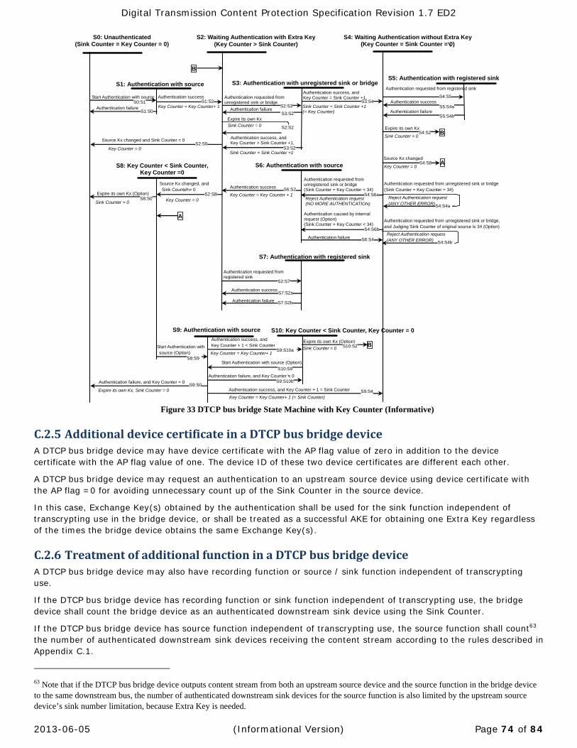
Digital Transmission Content Protection Specification Revision 1.7 ED2
2013-06-05 (Informational Version) Page 74 of 84
S2: Waiting Authentication with Extra Key(Key Counter > Sink Counter)
S1: Authentication with source
Start Authentication with source
Reject Authentication request (NO MORE AUTHENTICATION)
Authentication caused by internal request (Option) (Sink Counter = Key Counter < 34)
Authentication failure
Authentication success
S3: Authentication with unregistered sink or bridge
Authentication requested fromunregistered sink or bridge
Authentication failure
S0: Unauthenticated (Sink Counter = Key Counter = 0)
Key Counter = Key Counter+ 1
S6: Authentication with source
S0:S1 S1:S2 S3:S4
S4:S6b
Authentication success, and Key Counter = Sink Counter +1,
S6:S4Authentication failure
Authentication requested from unregistered sink or bridge (Sink Counter = Key Counter < 34)
S4:S6a
S4: Waiting Authentication without Extra Key(Key Counter = Sink Counter = 0)
S8: Key Counter < Sink Counter, Key Counter =0
S7: Authentication with registered sink
S9: Authentication with source
Expire its own Kx (Option)
Sink Counter = 0 Key Counter = 0
Start Authentication with source (Option)
Authentication success
Key Counter = Key Counter + 1
S2:S7
Authentication failure
Authentication success
Expire its own Kx, Sink Counter = 0
Authentication failure, and Key Counter = 0
Source Kx changed and Sink Counter = 0
B
Expire its own Kx
Sink Counter = 0
S5: Authentication with registered sink
Authentication requested from registered sink
Authentication success S4:S5
S5:S4a
Authentication requested from unregistered sink or bridge (Sink Counter = Key Counter = 34)
Reject Authentication request (ANY OTHER ERROR)
Authentication failure
B Expire its own Kx
Sink Counter = 0
A Source Kx changed
Key Counter = 0
BExpire its own Kx (Option)
Sink Counter = 0
S10: Key Counter < Sink Counter, Key Counter = 0
Authentication success, and Key Counter + 1 < Sink Counter
Authentication success, and Key Counter + 1 = Sink Counter
Key Counter = Key Counter+ 1 (= Sink Counter)
Start Authentication with source (Option)
Source Kx changed, and Sink Counter = 0
Authentication failure, and Key Counter = 0
S1:S0
Key Counter = 0 S2:S0
S8:S0 S2:S8
S8:S9
S9:S0
S9:S10a
S5:S4b
S2:S3
S3:S2
S2:S2
S6:S2
S7:S2a
S7:S2b
S10:S9
S9:S10b
S9:S4
A
S4:S4a
Sink Counter = Sink Counter +1(= Key Counter)
Authentication requested fromregistered sink
S4:S2
S4:S8
S10:S2
Authentication requested from unregistered sink or bridge, and Judging Sink Counter of original source is 34 (Option)
Reject Authentication request (ANY OTHER ERROR) S4:S4b
Authentication success, and Key Counter > Sink Counter +1, S3:S2Sink Counter = Sink Counter +1
Key Counter = Key Counter+ 1
Figure 33 DTCP bus bridge State Machine with Key Counter (Informative)
C.2.5 AdditionaldevicecertificateinaDTCPbusbridgedeviceA DTCP bus bridge device may have device certificate with the AP flag value of zero in addition to the device certificate with the AP flag value of one. The device ID of these two device certificates are different each other.
A DTCP bus bridge device may request an authentication to an upstream source device using device certificate with the AP flag =0 for avoiding unnecessary count up of the Sink Counter in the source device.
In this case, Exchange Key(s) obtained by the authentication shall be used for the sink function independent of transcrypting use in the bridge device, or shall be treated as a successful AKE for obtaining one Extra Key regardless of the times the bridge device obtains the same Exchange Key(s).
C.2.6 TreatmentofadditionalfunctioninaDTCPbusbridgedeviceA DTCP bus bridge device may also have recording function or source / sink function independent of transcrypting use.
If the DTCP bus bridge device has recording function or sink function independent of transcrypting use, the bridge device shall count the bridge device as an authenticated downstream sink device using the Sink Counter.
If the DTCP bus bridge device has source function independent of transcrypting use, the source function shall count63 the number of authenticated downstream sink devices receiving the content stream according to the rules described in Appendix C.1.
63 Note that if the DTCP bus bridge device outputs content stream from both an upstream source device and the source function in the bridge device to the same downstream bus, the number of authenticated downstream sink devices for the source function is also limited by the upstream source device’s sink number limitation, because Extra Key is needed.

Digital Transmission Content Protection Specification Revision 1.7 ED2
2013-06-05 (Informational Version) Page 75 of 84
AppendixD DTCPAsynchronousConnection
D.1 PurposeandScopeAppendix D specifies the mechanisms to use DTCP for Asynchronous Connection (AC). All aspects of the IEEE 1394 DTCP isochronous functionally described in Volume 1 body and the other Appendices are preserved and this appendix only details AC specific rules or additions.
D.2 TransmissionofProtectedFrame
D.2.1 OverviewFrame is minimal transmission unit of AC. Before transmitting a Frame, AC between Producer (source device of AC) and Consumer (Sink device of AC) is established using AV/C commands. One or more Frames are transmitted from the Producer to the Consumer. After the Frame transmission, the AC is broken using AV/C command. AC does not specify the size of the Frame. AC does not use special header when transmitting the Frame. Only the Frame data is transmitted.
In case of DTCP-AC, DTCP specific information such as EMI, Odd/Even bit shall be transmitted. To transmit this information together with Frame data, Protected Content Packet is introduced. In case of DTCP-AC, the Producer converts a Frame to Protected Frame and transmitted it to the Consumer.
In this section, Protected Frame is defined and transmission methods for Protected Frame are specified.
D.2.2 ProtectedContentPacketProtected Content Packet is used to carry the Frame in DTCP-AC. Figure 34 shows the structure of Protected Content Packet.
msb lsb Header [0] Reserved (zero) (msb) Header [1] dp_length (9 bits 2-504) (lsb)Header [2] Reserved (zero)
Header [3]
Reserved (zero) EMI Odd/ Even
Reserved
(zero) Header [4]
: Header [7]
Reserved (zero)
PC[0]
Protected Content (8xN bytes: N=1-63)64
- - -
PC[8N-1] Figure 34 Structure of Protected Content Packet
Protect Content Packet has eight bytes header (PCP header) and Protected Content. PCP header has following field.
dp_length: the value of this field shows the size of Data Packet in bytes (2-504).
EMI: Refer to section 6.4.2
Odd/Even: Refer to section 6.3.3
Protected Content (i.e. Encryption Frame) consists of a Data Packet and zero padding bytes which are encrypted according to the value of EMI. The size of Protected Content is multiple of 8 bytes. Figure 35 shows the structure of Data Packet.
64 In case of AES-128 optional cipher, N=2-63.

Digital Transmission Content Protection Specification Revision 1.7 ED2
2013-06-05 (Informational Version) Page 76 of 84
msb lsb Header [0] Reserved (zero) CT DB[0]
Data Block (M bytes: M=1-503)
- - - DB[M-1]
Figure 35 Structure of Data Packet
Data Packet has one byte header (DP header) and a Data Block. DP header has following field.
CT (Content Type): specifies the treatment of EMI/Embedded CCI for the Data Block in the Data Packet and the value of which are described in following table:
CT Definition Meaning
02 Audiovisual
Content Rules for audiovisual device functions described in Section 6.4.4 are applied
12 Audio Content Rules for audio device functions described in Section 6.4.5 are applied
Table 41 Content Type
Data Block contains a part of the data in the Frame to be transmitted through DTCP-AC.

Digital Transmission Content Protection Specification Revision 1.7 ED2
2013-06-05 (Informational Version) Page 77 of 84
D.2.3 ConstructionofProtectedFrameWhen a Frame is transmitted using DTCP, the Frame is divided into one or more Data Blocks from the top of the Frame. The maximum size of the Data Block is 503 bytes. When the value of EMI and CT are not changed in the middle of the Frame, the size of all Data Blocks is 503 byte except the last one which may contain less than 503 byte. When the value of EMI and/or CT is changed in the middle of the frame, the size of the Data Block before the changing point may contain less than 503 byte, so that a Data Packet contains the data which has the same EMI and the same CT.
Data Packet consists of one byte DP header and a Data Block. Data Packet size is within the inclusive range of 2 to 504bytes. If the size of the Data Packet is not multiple of 8 bytes, Encryption Padding bytes are added so that encryption size becomes multiple of 8 bytes. The size of the Encryption Padding bytes is from 0 to 765. The value of each padding byte is 0016.
A Data block and Encryption Padding bytes are encrypted according to the value of EMI, and becomes a Protected Content. The Size of the Protected Content is 8 x N bytes (N= 1, 2,.. 63). Protected Content Packet consists of 8 bytes PCP header and a Protected Content. When the size of a Protected Content Packet is not equal to 512 bytes, Alignment Padding bytes are added so that PCP header is located at every 512 bytes in the Protected Frame. The size of the Alignment Padding bytes is 8 x M bytes (M= 0, 1,.. 62). Alignment Padding bytes shall be used only when next Protected Content Packet has different EMI or CT during a Protected Frame transmission.
Following figure shows the generic construction of Protected Content Packet in the Protected Frame.
Figure 36 Generic Construction of Protected Content Packet in the Protected Frame
D.2.4 NCUpdateProcessFor DTCP-AC, the NC shall be updated after a Protected Frame is transmitted. If the size of a Protected Frame is larger than 32,768PCPs (16Mbytes), the NC shall be updated every 32,768PCPs transmission. NC is updated by incrementing it by 1 mod 264.
If a device has DTCP functionality for both isochronous transmission as a source device and AC as a Producer, the device may use different NC for an isochronous transmission and AC. If a Producer has plural asynchronous output plugs, the Producer may use different NC for each plug.
D.2.5 DurationofExchangeKeysThe KX for isochronous transmission shall also be used for KX for AC. KX for AC shall not be expired as long as AC is established. When all ACs of the Producer are broken, KX of AC is recommended to be expired as long as the Producer is stopping all isochronous output as a source device.
65 In case of AES-128 optional cipher, when the size of Data Packet is 2 through 15 bytes, the size of Encryption Padding bytes becomes 1 to 14 bytes. When the size of Data Packet is 16 through 504 bytes, Encryption Padding becomes 0 to 7 bytes.

Digital Transmission Content Protection Specification Revision 1.7 ED2
2013-06-05 (Informational Version) Page 78 of 84
D.2.6 FrameTransfertypeAC specifies two types of frame transfers. They are file-type transfers and stream-type transfers.
D.2.6.1 File‐typeTransferIn file-type transfers, all of the selected frame data in the Producer is transmitted to the Consumer. DTCP-AC described in this Appendix is applied to file-type transfers.
D.2.6.2 Stream‐typeTransferDTCP-AC for stream-type transfers is a NOT ESTABLISHED feature2 that is not currently specified.
D.3 EmbeddedCCIEmbedded CCI is carried as part of the content stream. Many content formats including MPEG have fields allocated for carrying the CCI associated with the stream. The definition and format of the CCI is specific to each content format. Information used to recognize the content format should be embedded within the content.
D.4 AKECommandExtensions
D.4.1 StatusFieldIn the AKE command, status field is used to query the status of the target device. A Producer shall not use the value of 00102 (No isochronous output) and 00112 (No point to point connection) when the Producer has at least one AC on its Serial Bus Asynchronous Output Plugs. When a Producer does not have any AC on its Serial Bus Asynchronous Output Plugs, the Producer may use these values according to the rules described in section Error! Reference source not found..
As for the usage of status field of CONTENT_KEY_REQ subfunction for DTCP-AC and SET_DTCP_MODE subfunction, refer to section Error! Reference source not found. and Error! Reference source not found. respectively.

Digital Transmission Content Protection Specification Revision 1.7 ED2
2013-06-05 (Informational Version) Page 79 of 84
AppendixE ContentManagementInformation(CMI)
E.1 General
E.1.1 PurposeandScopeContent Management Information (CMI) refers to usage rules associated with the content (e.g. CCI, DOT, Copy-count, etc.) which can be transmitted over DTCP as defined by DTLA.
The CMI is sent out in CMI Descriptor where each CMI Descriptor has its own ID, format and rules as defined by DTLA. Each unique CMI Descriptor ID refers to specific set of CMI. CMI Field consists of one or more CMI Descriptor. Source devices and Sink devices supporting CMI shall follow the corresponding rules for each CMI Descriptor defined in the following sections. Source devices shall not send any CMI Descriptor which is not supported by themselves except the case of the DTCP Bus Bridging and the case when DTLA approves.
Note that new CMI Descriptor may be additionally defined and transmitted with the CMI Descriptors currently defined. CMI descriptors allow for future expandability by either defining new descriptors or expansion of a currently defined descriptor. In the event that additional usage rule is added to a currently defined descriptor, the length of the CMI Descriptor Data field may be extended and the descriptor byte length value may be changed. If this occurs, currently defined fields in the CMI Descriptor Data shall not be altered to ensure backward compatibility. All devices shall be designed so that any change to the descriptor byte length value that results from an extension of the CMI Descriptor Data field shall not prevent access to contents of the CMI Descriptor Data field defined as of the time the device is manufactured.
Here is one example. Suppose CMI Descriptor-X has a set of usage rules. CMI Descriptor-Y is defined with a set of other usage rules later. A source device which supports the CMI Descriptor-X and CMI Descriptor-Y sends both CMI Descritpor-X and CMI Descriptor-Y. When a sink device does not support CMI Descriptor-Y the sink device may use the received content in accordance with the usage rules defined in the CMI Descriptor-X if the sink device supports the CMI Descriptor-X.
Here is another example. Suppose CMI Descriptor-A has a set of usage rules. CMI Descriptor-B has another set of usage rules. CMI Descriptor-C is defined with a set of other rules later. A source device which supports all CMI Descriptors sends CMI Descriptor- A and CMI Descriptor-C. When a sink device which supports both CMI Descriptor-A and CMI Descriptor-C the sink device may use the received content in accordance with the usage rules defined in CMI Descriptor-C if the sink device supports CMI Descriptor-C. In this case the sink device shall ignore the usage rules defined in the CMI Descriptor-A.
Here is another example. Suppose CMI Descriptor-D has a set of usage rules D-1, D-2 and D-3. CMI Descriptor-E with a set of usage rules D-1, D-2, D-3 and D-4 is defined later and the usage rule D-4 defines that a sink device may ignore D-4. A new source device which supports both old CMI Descriptor-D and new CMI Descriptor-E can send both CMI Descriptor-D and CMI Descriptor-E. An old sink device which supports CMI Descriptor-D only can use the received content in accordance with old CMI Descriptor-D.

Digital Transmission Content Protection Specification Revision 1.7 ED2
2013-06-05 (Informational Version) Page 80 of 84
E.1.2 GeneralRulesforSourceDevicesThe following are the rules for source devices that support CMI66:
Source devices shall not send content associated with a CMI Field before getting some indicationor that a sink device supports CMI, such as the CMI_REQ subfunction. CAPABILITY REQ2 subfunction, or some other method.
Source devices shall use the Alternate Content Key for the encryption of content associated with a CMI Field. When source devices send more than one CMI Descriptors in a CMI Field, the following rules shall be kept:
CMI Descriptors shall be sent in ascending order of CMI Descriptor ID. The same CMI Descriptor shall not be contained in a single CMI Field. CMI Descriptors shall be
concatenated without any space. The set of CMI Descriptor IDs shall not be changed while the value of CMI Descriptor Data may be
changed during content transmission. When source devices send multiple streams with MPEG-TS using DTCP_descriptors, CMI Descriptors which
provide a single set of content management information for all streams, such as the CMI Descriptor 1, shall not be used unless information in the CMI Descriptor is consistent with information in the DTCP_descriptor of any streams.
E.1.3 GeneralRulesforSinkDevicesThe following are the rules for sink devices that support CMI:
When sink devices receive content associated to a CMI Field, they shall process the content in accordance with the usage contained in the CMI Field. Unless specified by a CMI Descriptor rule, sink devices shall use only the information in CMI Field as usage rules.
When sink devices receive a CMI Field that contains more than one CMI Descriptor, o Sink devices shall use the usage rules of only one of the supported CMI Descriptors and ignore the
other CMI Descriptors. Sink devices may select any one of the supported CMI Descriptors. o When sink devices receive a CMI Field that does not contain the CMI Descriptor 0, they shall discard
the content. For Bus Bridge devices, even if they support none of the received CMI Descriptor(s) they may output the
content with the same CMI Field. When a sink device does not support any of the CMI Descriptors in a CMI Field it shall discard all content
associated to the CMI Field.
E.2 CMIFieldCMI Field may consist of one or more CMI Descriptors. Every CMI Descriptor shall be one byte aligned. CMI Descritpors shall be contained in ascending order of CMI Descriptor ID.
An example of CMI Field is described in the following figure.
msb lsb CMI Field[0..M] CMI Descriptor X
CMI Field [M+1..N] CMI Descriptor Y
CMI Field [0..M]: Contains CMI Descriptor X format data.
CMI Field [M+1..N]: Contains CMI Descriptor Y format data.
66 Note that device supporting CMI only are not interoperable with devices which do not support CMI, and not fully interoperable if the same CMI Descriptor is not supported.

Digital Transmission Content Protection Specification Revision 1.7 ED2
2013-06-05 (Informational Version) Page 81 of 84
E.3 CMIDescriptorDescriptions
E.3.1 CMIDescriptorGeneralFormatThe general format of CMI Descriptor except CMI Descriptor 0 is as follows:
msb lsb CMI Descriptor ID [0] ID
Extension [0] Extension Byte Length [0]
Byte length of CMI Descriptor Data (16 bits) Byte Length [1]
CMI Descriptor Data [0] Usage Rules -
CMI Descriptor Data [N-1]
CMI Descriptor ID [0]: Contains ID field. DTLA assigns ID.
Extension [0]: Is specified by each CMI Descriptor.
Byte Length [0..1]: Denotes byte length of Usage Rules field, where it is less than or equal to 64KB.
CMI Descriptor Data [0..N-1]: Represents usage rules and there is no usage rule when Byte Length field is zero.
When sink devices receive CMI Descriptor which has the Extension field of non-zero value, sink devices shall regard it as unsupported CMI Descriptor, and shall ignore the following fields. Note that this CMI Descriptor may have extended Byte Length field by using Extention field that may be more than 64KB.

Digital Transmission Content Protection Specification Revision 1.7 ED2
2013-06-05 (Informational Version) Page 82 of 84
E.3.2 CMIDescriptor0
E.3.2.1 CMIDescriptor0FormatThe format of CMI Descriptor 0 is as follows:
msb lsb CMI Descriptor ID [0] ID (0016)
Extension [0] 0016 Byte Length [0]
Byte length of CMI Descriptor 0 data Byte Length [1]
CMI Descriptor Data [0] Reserved (00002) C_T
C_T field indicates the type of content that is associated to this CMI Descriptor 0 and has the following values:
Value Description
00002 Audiovisual content
00012 Audio content
00102..11112 Reserved
Table 42 C_T Field
E.3.2.2 RulesforSourceDevicesSource devices shall support and always insert this CMI Descriptor.
E.3.2.3 RulesforSinkDevicesWhen sink devices use this CMI Descriptor, sink devices shall behave as Format-non-cognizant sink functions.
Sink devices with rendering functions shall support this CMI Descriptor.
Sink devices shall regard CMI Descriptor 0 as unsupported when the sink device does not support the value in the C_T field.
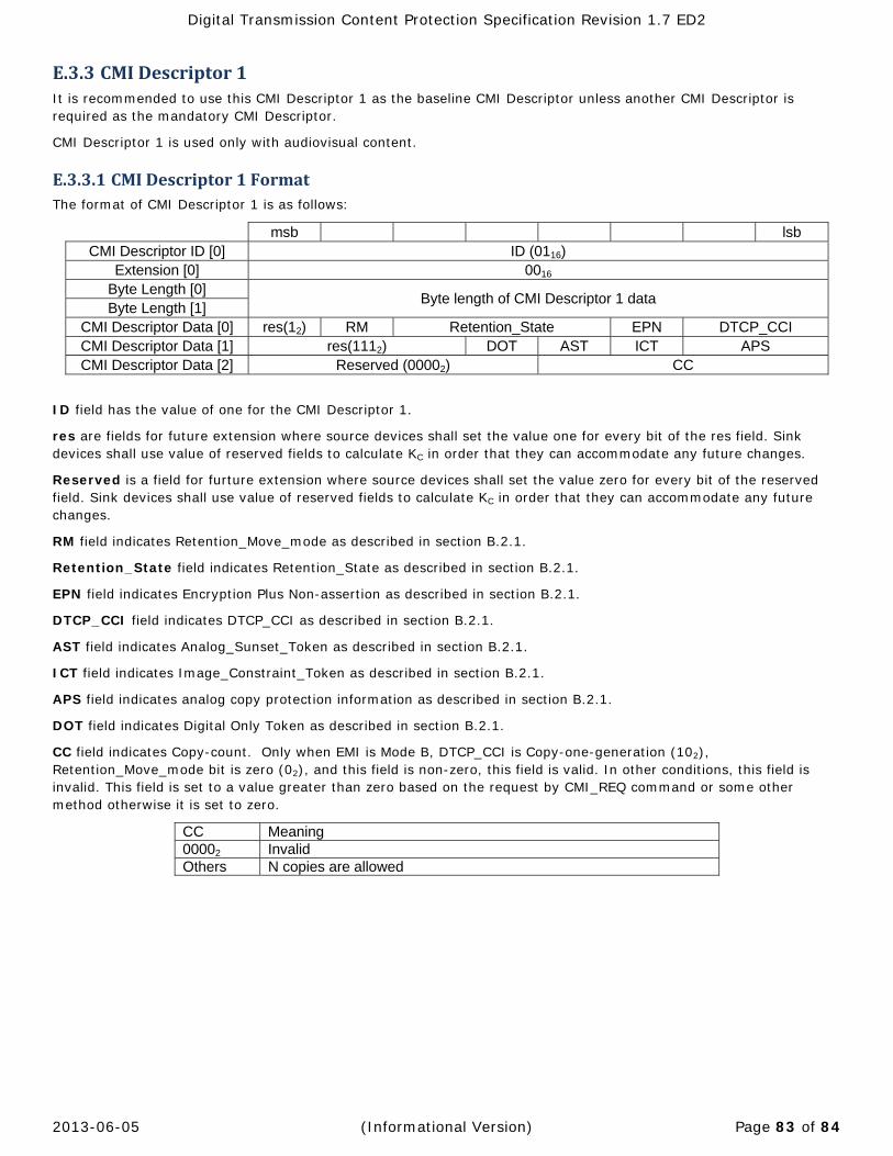
Digital Transmission Content Protection Specification Revision 1.7 ED2
2013-06-05 (Informational Version) Page 83 of 84
E.3.3 CMIDescriptor1It is recommended to use this CMI Descriptor 1 as the baseline CMI Descriptor unless another CMI Descriptor is required as the mandatory CMI Descriptor.
CMI Descriptor 1 is used only with audiovisual content.
E.3.3.1 CMIDescriptor1FormatThe format of CMI Descriptor 1 is as follows:
msb lsb CMI Descriptor ID [0] ID (0116)
Extension [0] 0016 Byte Length [0]
Byte length of CMI Descriptor 1 data Byte Length [1]
CMI Descriptor Data [0] res(12) RM Retention_State EPN DTCP_CCI CMI Descriptor Data [1] res(1112) DOT AST ICT APS CMI Descriptor Data [2] Reserved (00002) CC
ID field has the value of one for the CMI Descriptor 1.
res are fields for future extension where source devices shall set the value one for every bit of the res field. Sink devices shall use value of reserved fields to calculate KC in order that they can accommodate any future changes.
Reserved is a field for furture extension where source devices shall set the value zero for every bit of the reserved field. Sink devices shall use value of reserved fields to calculate KC in order that they can accommodate any future changes.
RM field indicates Retention_Move_mode as described in section B.2.1.
Retention_State field indicates Retention_State as described in section B.2.1.
EPN field indicates Encryption Plus Non-assertion as described in section B.2.1.
DTCP_CCI field indicates DTCP_CCI as described in section B.2.1.
AST field indicates Analog_Sunset_Token as described in section B.2.1.
ICT field indicates Image_Constraint_Token as described in section B.2.1.
APS field indicates analog copy protection information as described in section B.2.1.
DOT field indicates Digital Only Token as described in section B.2.1.
CC field indicates Copy-count. Only when EMI is Mode B, DTCP_CCI is Copy-one-generation (102), Retention_Move_mode bit is zero (02), and this field is non-zero, this field is valid. In other conditions, this field is invalid. This field is set to a value greater than zero based on the request by CMI_REQ command or some other method otherwise it is set to zero.
CC Meaning 00002 Invalid Others N copies are allowed

Digital Transmission Content Protection Specification Revision 1.7 ED2
2013-06-05 (Informational Version) Page 84 of 84
E.3.3.2 RulesforSourceDevicesWhen source devices do not use CC field, they shall set CC field to zero.
When source devices send this CMI Descriptor, they may transmit MPEG-TS content without DTCP_descriptors unless the other CMI Descriptor requires insertion of DTCP_descriptor67.
Source devices shall not use this CMI Descriptor when transmitting MPEG-TS content with DTCP descriptor and value of this CMI Descriptor is inconsistent with value of DTCP_descriptor in combination with EMI (for example when the MPEG-TS content consists of multiple programs or the content consists of a single program that includes multiple DTCP_descriptors).
E.3.3.3 RulesforSinkDevicesWhen sink devices receive a content stream with invalid condition about CC field as specified in E.3.3.1, they shall ignore CC field.
E.3.4 CMIDescriptor2
E.3.4.1 CMIDescriptor2FormatThe format of CMI Descriptor 2 is as follows:
msb lsb CMI Descriptor ID [0] ID (0216)
Extension [0] 0016 Byte Length [0]
Byte length of CMI Descriptor 2 data Byte Length [1]
CMI Descriptor Data [0] CC Reserved (00002)
ID field has the value of two for the CMI Descriptor 2.
CC field indicates CC as described in section E.3.3.1
Reserved field is the area for future extension. Source devices shall set zero to every bit in this field. Sink devices shall use value of reserved field to calculate KC in order that they can accommodate any future changes.
E.3.4.2 RulesforSourcesDevicesSource devices shall not insert this CMI Descriptor except when transmitting content stream in MPEG-TS format. When source devices use this CMI Descriptor source devices shall insert the DTCP_descriptor in the content stream in accordance with the Appendix B. For clarification, both CMI Descriptor 1 and CMI Descriptor 2 may be sent in the CMI Field.
When source devices do not use CC field, they shall set CC field to zero. The CC field shall not be used for content other than audiovisual content.
Source devices shall use this CMI Descriptor 2 when transmitting content in MPEG-TS format with DTCP_descriptor.
E.3.4.3 RulesforSinkDevicesWhen sink devices use this CMI Descriptor, associated content shall be handled based on the usage rule information contained in the DTCP_descriptor in accordance with the Appendix B.
CC field shall be handled as it is contained in the DTCP_descriptors within every program info loop of the PMT. When sink devices receive a content stream with a CC field indicates invalid condition as specified in E.3.3.1 they shall ignore CC field.
If neither the DTCP_descriptor nor Embedded CCI is detected, sink devices shall not use this CMI Descriptor.
67 Note that there are technologies that require the DTCP output to set the DTCP_descriptor. In that case the CMI Descriptor 2 is also used (see E.3.4.2).

![RadioVIS Technical Specification · An existing specification allows the transmission of slideshow over DA Digital Radio [1]. The present document defines a similar methodology based](https://static.fdocuments.in/doc/165x107/5e7989ce0b513b2c04485443/radiovis-technical-specification-an-existing-specification-allows-the-transmission.jpg)