BB Torrentula Manual
61
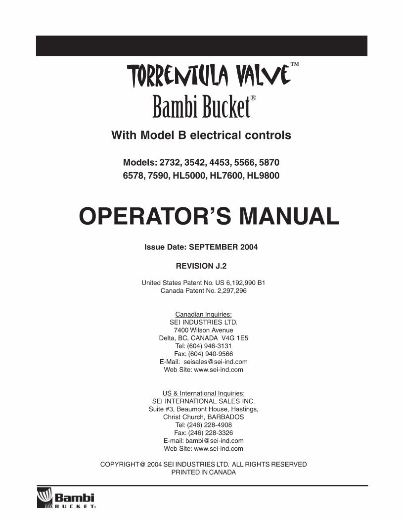
T T Tor or or or orren ren ren ren rentula V tula V tula V tula V tula Val al al al alv v ve e e Bambi Bucket With Model B electrical controls OPERATOR’S MANUAL TM ® Issue date: SEPTEMBER 2004 REVISION J.2
-
Upload
nuno-rodrigues -
Category
Documents
-
view
219 -
download
11
Transcript of BB Torrentula Manual
TTTTTorororororrenrenrenrenrentula Vtula Vtula Vtula Vtula ValalalalalvvvvveeeeeBambi Bucket
With Model B electrical controls
OPERATOR’S MANUAL
TM
®
Issue date: SEPTEMBER 2004REVISION J.2
TTTTTorororororrenrenrenrenrentula Vtula Vtula Vtula Vtula ValalalalalvvvvveeeeeBambi Bucket
With Model B electrical controls
Models: 2732, 3542, 4453, 5566, 58706578, 7590, HL5000, HL7600, HL9800
OPERATOR’S MANUALIssue Date: SEPTEMBER 2004
REVISION J.2
United States Patent No. US 6,192,990 B1Canada Patent No. 2,297,296
Canadian Inquiries:SEI INDUSTRIES LTD.
7400 Wilson AvenueDelta, BC, CANADA V4G 1E5
Tel: (604) 946-3131Fax: (604) 940-9566
E-Mail: [email protected] Site: www.sei-ind.com
US & International Inquiries:SEI INTERNATIONAL SALES INC.
Suite #3, Beaumont House, Hastings,Christ Church, BARBADOS
Tel: (246) 228-4908Fax: (246) 228-3326
E-mail: [email protected] Site: www.sei-ind.com
COPYRIGHT@ 2004 SEI INDUSTRIES LTD. ALL RIGHTS RESERVEDPRINTED IN CANADA
TM
®
TABLE OF CONTENTS
Page #
1. INTRODUCTION TO THE BAMBI BUCKET 1
2. PREFLIGHT SAFETY CHECK 2
3. DEPLOYING THE BAMBI BUCKET 33.1 Attaching to Cargo Hook3.2 Interfacing with the aircraft power supply3.3 Operator’s control interface3.4 Installation of non-standard breakaway connectors3.5 Pilot-operated controls3.6 Longline conductor specifications3.7 Conversion of Model “A” electrical controls to Model “B” protocol
Fig 3.1 Bambi Bucket suggested installation diagram 6
3.8 Checking suspension cable length - Avoid Tailrotor Strikes!3.9 Instant Deployment System, IDS
4. FLYING THE BAMBI BUCKET 94.1 Flying empty4.2 Flying full
5. FILLING THE BUCKET 105.1 Variable fill capability5.2 Adjusting the IDS adjustment chain5.3 Shallow fill capability5.4 Filling from a Fireflex Tank or Heliwell Tank
6. USING FOAM 126.1 Sacksafoam foam injection system6.2 Interfacing with the Torrentula Valve Controller
7. DUMPING THE BUCKET 137.1 Dump pattern7.2 Dump speed7.3 Operation of the dump valve
8. LANDING 14
9. PACKING THE BUCKET 15
10. STORING THE BUCKET 17
11. MAINTENANCE & TROUBLESHOOTING 1811.1 Introduction11.2 Description of Torrentula Valve and actuating
mechanism11.3 Torrentula Valve electrical system description11.4 Routine maintenance procedures11.5 Unscheduled maintenance
Fig 11.2 Troubleshooting Chart 23
11.6 Electrical controls troubleshooting

TABLE OF CONTENTS
Page #
12. SHELL & SUSPENSION LINE MAINTENANCE 2912.1 Suspension line replacement12.2 M-Strap replacement12.3 Bucket patching12.4 Bucket patching with a hot air gun12.5 Bucket patching with repair clamps12.6 IDS hub/spokes replacement
13. WARRANTY 33
14. SPECIFICATIONS 34
15. CONTROL HEAD PARTS 35
16. TORRENTULA VALVE PARTS, MODELS HL5000 - HL9800 37
17. TORRENTULA VALVE PARTS, MODELS 5566 - 7590 39
18. TORRENTULA VALVE PARTS, MODELS 2732 - 4453 41
19. WIRING DIAGRAMS 43
20. ELECTRICAL CONTROLS PARTS 48
21. BAMBI BUCKET SHELL PARTS 51
22. IDS SYSTEMS 53
23. RIGGING 55
24. PACKAGING 57
1
This manual provides helicopter operators with information on the operation and maintenance of the BambiBucket with the Torrentula valve.
Since its introduction in 1983, the Bambi Bucket has become the industry standard for helicopter firefightingfor over 1000 commercial operators and government agencies worldwide. This acceptance by the industryis a result of the effectiveness, reliability, simplicity and ease of use of the Bambi Bucket. Adding the newTorrentula Valve model to the already renowned Bambi Bucket family boosts fire suppression capabilities,thus making it an indispensable tool for attacking wildland and urban fires.
The Bambi Bucket with the Torrentula Valve features revolutionary new dump control technology. By simplyactuating a switch to open or close the Torrentula Valve the operator can get a variable flow and/or multipledrops of water from the bucket. The bucket can be bottom filled easily by holding the valve in the “openposition”. No prior experience is required to quickly master operation of the Torrentula valve. The bucketrequires no assembly. Once airborne, the operator quickly becomes familiar with the flight characteristicsof the bucket. Several fills will provide familiarity with the variable fill capability of the bucket as well as withthe variable, multiple dump capability of the Torrentula Valve.
Introduced in June 2003 are the new Model B electrical controls for the operation of the dump valve. ModelB controls feature a number of upgrades, including: microprocessor-based control logic, all aluminumenclosure, Mil-W-22759/16 wiring, Mil-C-5809 Circuit protection and convenient, all unique, Mil-C-5015wire harness connections.
Available for retrofit or factory installation on all Torrentula Valve Bambi Buckets is the new PowerFill Ishallow draft pumping system. The addition of the PowerFill I pumps gives the operator the ability to performrapid and complete bottom fills from sources a shallow as 18” (0.46m) deep. The new Model B electricalcontrols have accomodations for the modular addition of the PowerFill I system.
Please read this manual prior to flying the bucket, particularly the sections on deploying, filling and dumping.If you experience problems, please refer to the manual. Sections 11 and 12, Maintenance andTroubleshooting, may be especially helpful.
For your own protection and for longer bucket life, always read the instructions and warnings. Ignoringthem could result in personal injury, bucket or aircraft damage. The warning notices are divided by theseverity of the outcome into WARNING and CAUTION.
WARNING: Hazards or unsafe practices which could result in personal injury or death
CAUTION: Hazards or unsafe practices which could result in minor personal injury orproperty damage
SEI offers complete parts supply and repair facilities for the Bambi Bucket. For maintenance and repairpurposes, parts diagrams and descriptions are provided in Sections 15 to 22. SEI also offers the BambiBucket Repair Assessment Manual as a guidline for determining the ongoing operational status of theBambi Bucket.
When ordering parts, please provide the Model and Serial number of your Bambi Bucket.
Additional copies of this manual are available from SEI Industries Ltd.
1. INTRODUCTION TO THE BAMBI BUCKET

2
Just as the pilot preflights his aircraft, he should alsopreflight his Bambi Bucket each day.
1) Check the bottom chain and look for anytears in the fabric straps; check thelockwire or tie wraps on the shackles
2) Check for loose bolts around the bucketshell: IDS brackets at the top, FCAS(Cinch Strap) brackets at the mid point,wear strips at the bottom.
3) Check the diagonal “M-straps” thatconnect the suspension cables to the topof the bucket and examine for any wear.
4) Visually check the multi-dump valve,particularly the seals.
5) Visually check valve guard structure forbending or cracks.
6) Check the internal or external Frusto-conical Arrest System (FCAS or “cinchstrap”).
7) Check the suspension cables for frays,kinks or loose swages.
8 Check that the solid metal ballast bars aresecurely attached.
9) Check the control head for secure fittings.
CAUTION: Make sure the Bambi Bucket shelldoes not rub against the valve on the inside ofthe bucket. This may impede the movement ofthe valve, and may damage the valve and/orcontrol head.
2. PREFLIGHT SAFETY CHECK
CAUTION: Never operate the bucketwith the control head cover removed.
3
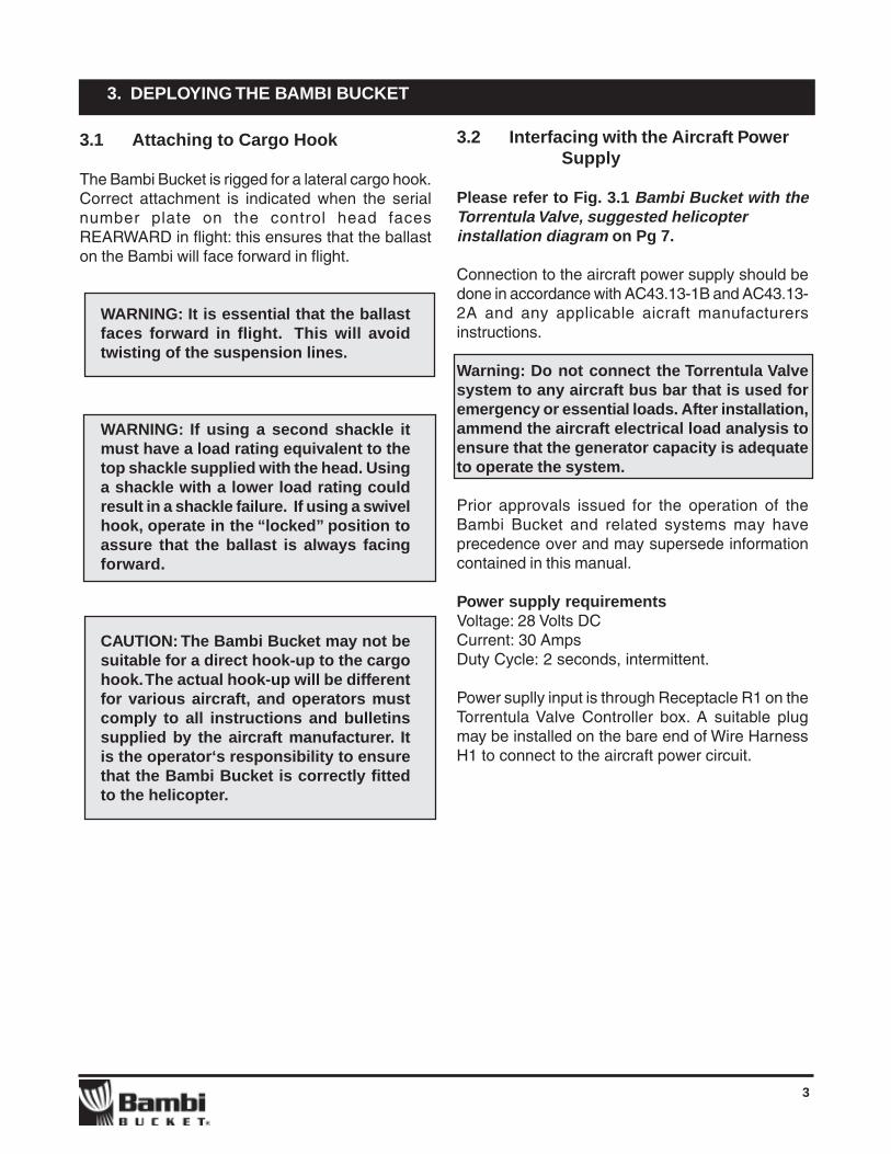
3.2 Interfacing with the Aircraft PowerSupply
Please refer to Fig. 3.1 Bambi Bucket with theTorrentula Valve, suggested helicopterinstallation diagram on Pg 7.
Connection to the aircraft power supply should bedone in accordance with AC43.13-1B and AC43.13-2A and any applicable aicraft manufacturersinstructions.
Warning: Do not connect the Torrentula Valvesystem to any aircraft bus bar that is used foremergency or essential loads. After installation,ammend the aircraft electrical load analysis toensure that the generator capacity is adequateto operate the system.
Prior approvals issued for the operation of theBambi Bucket and related systems may haveprecedence over and may supersede informationcontained in this manual.
Power supply requirementsVoltage: 28 Volts DCCurrent: 30 AmpsDuty Cycle: 2 seconds, intermittent.
Power suplly input is through Receptacle R1 on theTorrentula Valve Controller box. A suitable plugmay be installed on the bare end of Wire HarnessH1 to connect to the aircraft power circuit.
3. DEPLOYING THE BAMBI BUCKET
3.1 Attaching to Cargo Hook
The Bambi Bucket is rigged for a lateral cargo hook.Correct attachment is indicated when the serialnumber plate on the control head facesREARWARD in flight: this ensures that the ballaston the Bambi will face forward in flight.
WARNING: It is essential that the ballastfaces forward in flight. This will avoidtwisting of the suspension lines.
WARNING: If using a second shackle itmust have a load rating equivalent to thetop shackle supplied with the head. Usinga shackle with a lower load rating couldresult in a shackle failure. If using a swivelhook, operate in the “locked” position toassure that the ballast is always facingforward.
CAUTION: The Bambi Bucket may not besuitable for a direct hook-up to the cargohook. The actual hook-up will be differentfor various aircraft, and operators mustcomply to all instructions and bulletinssupplied by the aircraft manufacturer. Itis the operator‘s responsibility to ensurethat the Bambi Bucket is correctly fittedto the helicopter.

4
3. DEPLOYING THE BAMBI BUCKET
3.5 Pilot-operated controls
Where pilot control of the systems is specified, theoperator may wish to utilize existing switches onthe flight controls, or have them installed for easeof use by the pilot. SEI Industries can supply anoptional Pilot Controls Wire Harness for interfacewith the Torrenula Valve Controller if desired.
Before installation of pilot-operated controls, it isrecommended that you review the informationcontained in section 19.
All pilot controls wiring connected to receptacle R4should be #18 AWG or larger.
Required wiring
The function of the valve can be controlled withone +28 volts DC common lead, one lead for “open”and one lead for “close” (3 total). The switchconfiguration can consist of either a SPDT toggleswitch with center off, (on)-off-(on), or two pushbutton switches.
Valve position indicator lights
The wire harness may also include, where desired,leads for the indicator lights that indicate when thevalve is in the full “open” (green) or full “closed”(amber) positions.
PowerFill I controls
As standard equipment with all Torrentula electricalcontrols are accommodations for the operation ofthe optional PowerFill I pump system. If you arenot operating a PowerFill I system, you do not needto install the wiring specific to the operation of thepumps. However, you may want to consider thefuture addition of the pump system when doing theinitial installation for the operation of the valve.
3.3 Operator’s control interface
As standard equipment, all Torrentula ValveControllers are equipped with an Operator’sControl Grip that contains all the switches andindicators required for full operation of the dumpvalve and optional PowerFill I pump system.
The control grip is designed to fit comfortably ineither the left or right hand and is fully labelled asto the the function of each switch.
The control grip wire harness connects toreceptacle R4 on the Torrentula Valve Controllerbox face panel.
If pilot-operated controls are specified, thestandard control grip should be kept available formaintenance checks when the bucket system isremoved from the aircraft.
3.4 Installation of non-standard breakawayconnectorsSEI Industries supplies a single type of breakawayelectrical connectors for the connection of theTorrentula Valve electrical controls to the BambiBucket Control Head. The considerations forselection of these connectors included: availability,cost, ease of assembly and durability. Operatorsof Bambi Buckets may specify and install othertypes and makes of breakaway connectors to suittheir own specific operating requirements andconditions, provided:
1) The connectors are of a sufficient capacity toaccept the wire gauge as originally supplied withthe equipment, and/or larger wire gauges, as maybe required for extension of the electricalconductors for long line operations.
2) Where installed adjacent to and in conjunctionwith the load release mechanism, that they canseparate cleanly and with minimal force in theevent of an emergency jettison.
It is the responsibility of the operator to record,maintain and monitor any operator-specifiedmodifications to SEI Industries product.

5
3.6 Longline conductor specifications
Many operator’s of bucket systems use longlinelifting cables. For assistance in specifying theconductor cable assemblies for operating onlonglines, see fig 19.4 in Section 19.
3.7 Conversion of Model “A” electricalControls to Model “B” protocol
The Model “B” version of the Torrentula Valveelectrical controls was introduced in June of 2003.Many operators of Torrentula Bucket systems, whostill operate with the Model “A” controls may wishto upgrade their systems to be able to interfacethe buckets with the new Model “B” controls. Thisis a simple procedure that involves replacing theoriginal breakaway connectors with the new type,and modifying the pin protocol to match.
The power requirements and operationalprocedures are the same for both the old and thenew systems.
The information in this manual pertaining to theelectrical controls does not apply Model “A”systems. If you are operating a bucket with Model“A” controls, please refer to the operator’s manualoriginally supplied with the bucket.
Identification
All Model “A” controls are equipped with a greyPVC electrical enclosure, with attached powerleads.
Model “B” controls have a black aluminumenclosure with all detatchable wire leads.
With the exception of the breakaway connectors,there are no differences on the “bucket end” of thesystem.
See figure 19.5 in Section 19 for details on theconversion.
3. DEPLOYING THE BAMBI BUCKET

6
3. DEPLOYING THE BAMBI BUCKET
Fig 3.1 Bambi Bucket with the Torrentula Valve, suggested helicopter installation
7
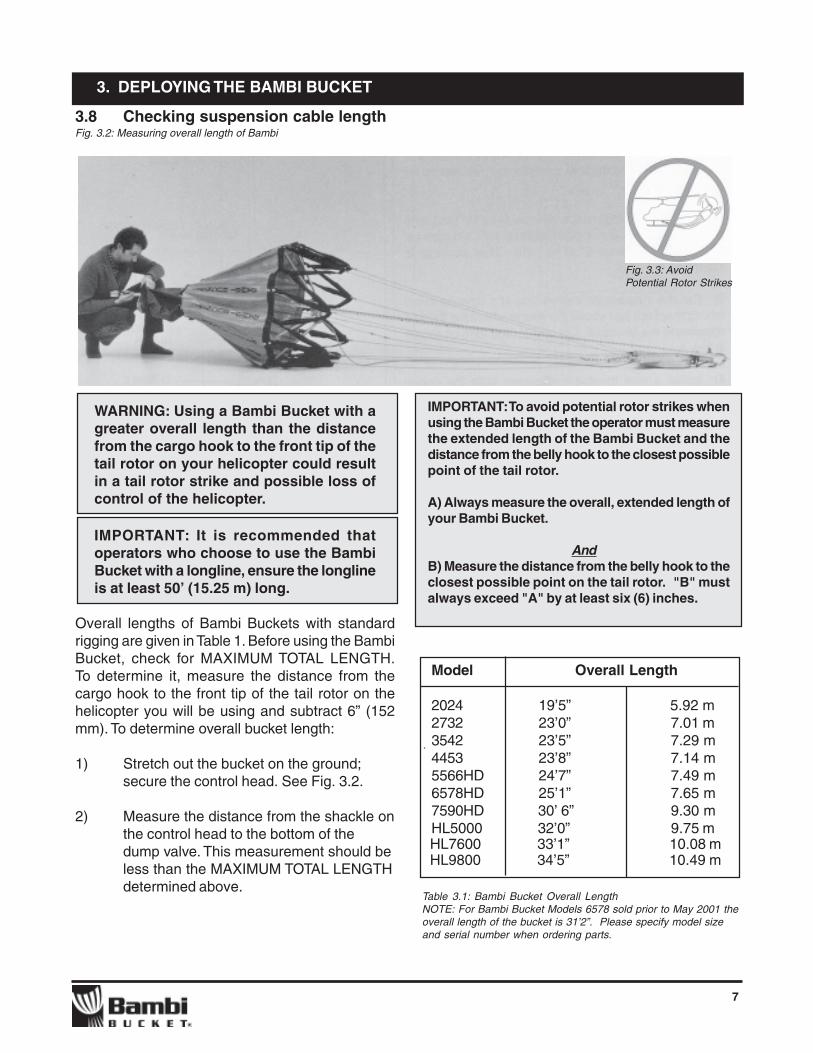
3.8 Checking suspension cable lengthFig. 3.2: Measuring overall length of Bambi
WARNING: Using a Bambi Bucket with agreater overall length than the distancefrom the cargo hook to the front tip of thetail rotor on your helicopter could resultin a tail rotor strike and possible loss ofcontrol of the helicopter.
IMPORTANT: It is recommended thatoperators who choose to use the BambiBucket with a longline, ensure the longlineis at least 50’ (15.25 m) long.
Overall lengths of Bambi Buckets with standardrigging are given in Table 1. Before using the BambiBucket, check for MAXIMUM TOTAL LENGTH.To determine it, measure the distance from thecargo hook to the front tip of the tail rotor on thehelicopter you will be using and subtract 6” (152mm). To determine overall bucket length:
1) Stretch out the bucket on the ground;secure the control head. See Fig. 3.2.
2) Measure the distance from the shackle onthe control head to the bottom of thedump valve. This measurement should beless than the MAXIMUM TOTAL LENGTHdetermined above.
3. DEPLOYING THE BAMBI BUCKET
Model Overall Length
2024 19’5” 5.92 m2732 23’0” 7.01 m3542 23’5” 7.29 m4453 23’8” 7.14 m5566HD 24’7” 7.49 m6578HD 25’1” 7.65 m7590HD 30’ 6” 9.30 mHL5000 32’0” 9.75 m
Table 3.1: Bambi Bucket Overall LengthNOTE: For Bambi Bucket Models 6578 sold prior to May 2001 theoverall length of the bucket is 31’2”. Please specify model sizeand serial number when ordering parts.
HL9800 34’5” 10.49 m
IMPORTANT: To avoid potential rotor strikes whenusing the Bambi Bucket the operator must measurethe extended length of the Bambi Bucket and thedistance from the belly hook to the closest possiblepoint of the tail rotor.
A) Always measure the overall, extended length ofyour Bambi Bucket.
AndB) Measure the distance from the belly hook to theclosest possible point on the tail rotor. "B" mustalways exceed "A" by at least six (6) inches.
HL7600 33’1” 10.08 m
Fig. 3.3: AvoidPotential Rotor Strikes

8
3.9 Instant Deployment System (IDS)
The instant deployment system (IDS) uses a huband spoke mechanism to automatically expand themouth of the bucket as soon as the suspensioncables take the weight of the Bambi.
On Torrentula Valve-equipped buckets, it isrecommended that the IDS should be deployedbefore flight so that a full function check of the valvecan be performed.
CAUTION: Operating the Torrentula valvewith the bucket collapsed may causedamage to the valve and/or control head.
When the bucket is full, the IDS Deployment Cableand hub Restrainer Cables should be slack; theyshould not bear any load. Their function is to positionthe hub and spoke mechanism to hold the bucketopen.
The main parts of the IDS are illustrated in Fig. 3.To deploy the IDS System on the ground, reachinto the bucket, grasp the hub of the IDS and pulloutward fully until the two cables from the hub tothe lower bucket shell are tight.
3. DEPLOYING THE BAMBI BUCKET
Fig. 3.4: Instant Deployment System, Main parts
9
4. FLYING THE BAMBI BUCKET
You may fly with the Torrentula Valve in the “open”or “closed” position, depending on your preference.
CAUTION: To protect the bottom valve seal, we recommend that the valve is closed during take-off and landing procedures.
4.1 Flying empty
The Bambi Bucket Has been flown at speeds to110 mph (176 kph) and has proven stable at allspeeds. Nevertheless, we suggest you build up tospeed slowly with your Bambi Bucket on yourhelicopter under the prevailing operating conditionsto determine a safe maximum speed.
4.2 Flying full
The dead weight of the load ensures differenthandling characteristics than when flying empty. Youwill notice that the Bambi Bucket does not “pulse”or “throb” under load in flight.

10
FCAS system
The Frusto-Conical Arrest System, FCAS, allowsthe operator to reduce the volume of the bucket toa preset percentage of maximum capacity.The FCAS is composed of a cinch strap attachedto the waist (vertical mid point) of the bucket.The cinch strap is marked with one or more loadlevels.
CAUTION: Do not tighten the cinch strappast the smallest load marking.Overtightening can damage the bucketshell.
Water volume can be adjusted on a Torrentula ValveBambi Bucket by opening and closing the valve torelease water. See Section 7: “Dumping theBucket”.
5. FILLING THE BUCKET
The Bambi Bucket with the Torrentula Valve canbe filled either by tipping the bucket with the valve“closed”, or by filling from the bottom up with thevalve “open”. The method used is based onoperator preference, speed of fill and the watersource.
The Torrentula Valve must be “closed” prior to lift-out from the source.
On the control panel, the green light will be onwhen the valve is in the “open” position; theamber light will be on when the valve is in the“closed” position.
It is not necessary to tow the Bambi Bucket tomake it sink.
WARNING: When filling the Bambi, donot execute an abrupt 90 degree pedalturn with the helicopter close to thewater while towing the bucket. In thisattitude there is the danger that theBambi suspension lines (as with anyother load) could get caught on a rearskid resulting in a dynamic rollover onliftout. This could cause personal injuryand helicopter damage. Check the loadand suspension cables with your mir-rors before liftout.
WARNING: Do not allow too much slackto occur on the Bambi Bucket suspen-sion lines when dipping. Lines couldsnag on submerged objects or parts ofthe bucket.
5.1 Variable fill capability
The pilot can vary the bucket’s volume, up to themaximum rated capacity, by the speed at which itis pulled from the water. As the submergedbucket is lifted, water pressure bends the bucketshell outward, increasing the bucket‘s volume.The greater the upward velocity, the greater thevolume of the bucket.
Fig. 5.1: Cinched Bucket, internal cinch strap

11
CAUTION: Snagging the Bambi onsubmerged objects could result inbucket shell damage.
5.4 Filling From a Fireflex orHeliwell Tank
The Heliwell tank is a transportable, field erectedwater tank of sufficient size to dip all models ofthe Bambi Bucket. The tank consists of tenaluminum panels with an internal vinyl fabric liner.There are 3 different sizes of Heliwell tanks:5,650; 9,425 and 14,900 USG.
The Fireflex TankTM is a self-supported open toptank that can be used as a dip tank for helicoptersequipped with the Bambi Bucket. See Table 5.1for recommended tank sizes for different modelsof the Bambi Bucket.
Bambi Bucket Empty Bucket Recommended Fireflex Tank
Model No. Height (in/mm) Tank Model Full Height
2024 39/.099 FFTF-2530 48/1.22 2732 43/1.09 FFTF-4048 60/1.52 3542 52/1.32 FFTF-5060 68/1.73 4453 52/1.32 FFTF-5060 68/1.73 5566 57/1.45 FFTF-80100 79/2.00 6578 58/1.47 FFTF-80100 79/2.00 7590 59/1.50 FFTF-80100 79/2.00 HL3800 72/1.83 FFTF-120144 93/2.36 HL5000 72/1.83 FFTF-120144 93/2.36 HL7600 86/2.18 FFTF-120144 93/2.36
Table 5.1: Fireflex Tank sizes for Bambi Bucket
5.3 Shallow Fill Capability
Filling the bucket from the bottom is an advantageof the Torrentula Valve model that the Standardmodels do not offer.
With the addition of the PowerFill I shallow draftpumping system, many previously inaccessiblewater sources such as ditches, ponds, streams,rivers, swamps, and relay tanks, can be utilized.
5.2 Adjusting the IDS adjustment chain
An IDS adjustment chain is fitted to all Torrentulavalve buckets. This chain must be adjusted whenusing the cinch strap to reduce bucket volume. Thechain is lengthened for lower fill settings (eg. 70%)to allow the IDS to rise and thereby reduce IDSstresses. This will avoid possible damage to theIDS. The chain is shortened for higher fill settings(eg. 90%) to retain the maximum bucket mouthdiameter and hence allow maximum filling effi-ciency. The recommended chain adjustments aresummarised in Fig. 5.2.
5. FILLING THE BUCKET
Fig.5.2: Adjusting the IDS Adjustment Chain
CAUTION: The lowest fill setting for allmodels is 70%. Overtightening thecinchstrap could damage the bucket.
12
The Bambi bucket is designed to be used with foam.All materials used in the manufacture of the BambiBucket are resistant to the chemical action of foam.
CAUTION: After using foam or retardant,cycle through several dumps with wateronly or hose down with fresh water. Thiswill prolong the bucket‘s life.
6.1 SACKSAFOAM Foam InjectionSystem
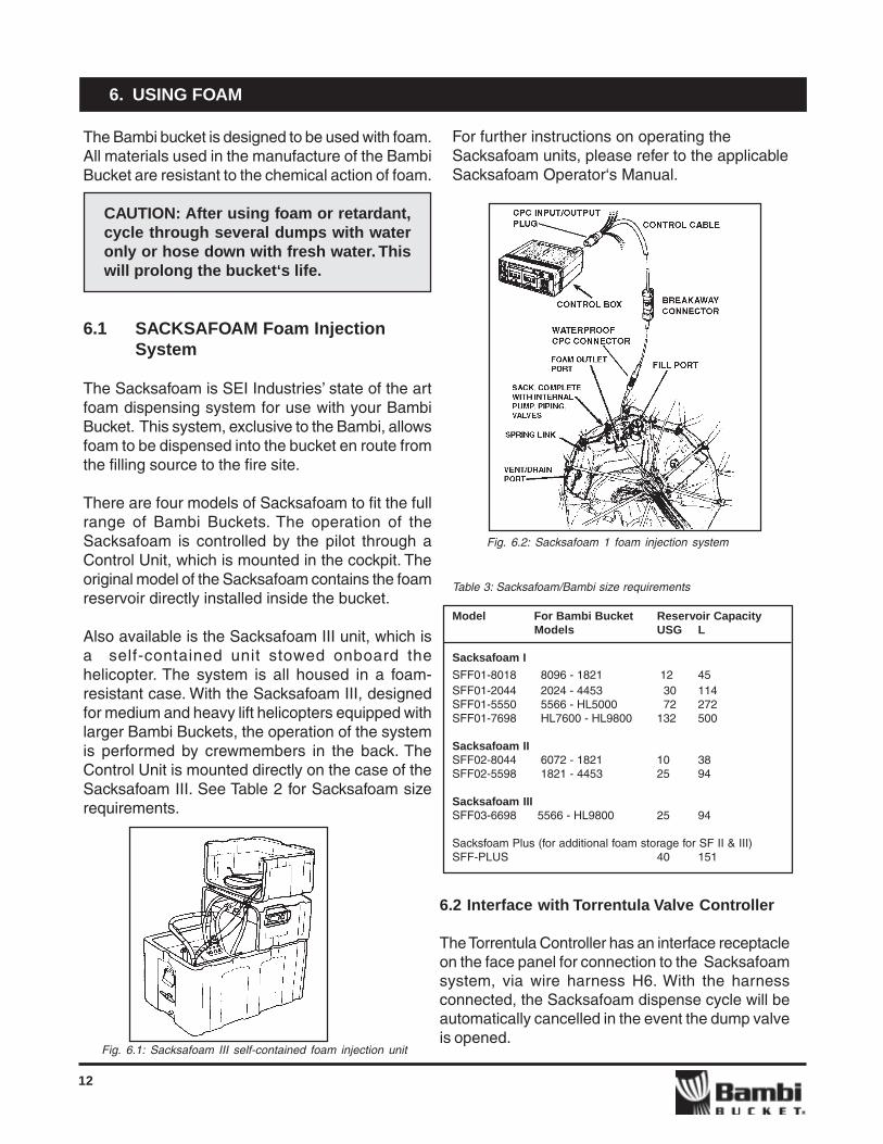
The Sacksafoam is SEI Industries’ state of the artfoam dispensing system for use with your BambiBucket. This system, exclusive to the Bambi, allowsfoam to be dispensed into the bucket en route fromthe filling source to the fire site.
There are four models of Sacksafoam to fit the fullrange of Bambi Buckets. The operation of theSacksafoam is controlled by the pilot through aControl Unit, which is mounted in the cockpit. Theoriginal model of the Sacksafoam contains the foamreservoir directly installed inside the bucket.
Also available is the Sacksafoam III unit, which isa self-contained unit stowed onboard thehelicopter. The system is all housed in a foam-resistant case. With the Sacksafoam III, designedfor medium and heavy lift helicopters equipped withlarger Bambi Buckets, the operation of the systemis performed by crewmembers in the back. TheControl Unit is mounted directly on the case of theSacksafoam III. See Table 2 for Sacksafoam sizerequirements.
6. USING FOAM
For further instructions on operating theSacksafoam units, please refer to the applicableSacksafoam Operator‘s Manual.
Fig. 6.2: Sacksafoam 1 foam injection system
Model For Bambi Bucket Reservoir CapacityModels USG L
Sacksafoam I
SFF01-8018 8096 - 1821 12 45SFF01-2044 2024 - 4453 30 114SFF01-5550 5566 - HL5000 72 272SFF01-7698 HL7600 - HL9800 132 500
Sacksafoam IISFF02-8044 6072 - 1821 10 38SFF02-5598 1821 - 4453 25 94
Sacksafoam IIISFF03-6698 5566 - HL9800 25 94
Sacksfoam Plus (for additional foam storage for SF II & III)SFF-PLUS 40 151
Fig. 6.1: Sacksafoam III self-contained foam injection unit
Table 3: Sacksafoam/Bambi size requirements
6.2 Interface with Torrentula Valve Controller
The Torrentula Controller has an interface receptacleon the face panel for connection to the Sacksafoamsystem, via wire harness H6. With the harnessconnected, the Sacksafoam dispense cycle will beautomatically cancelled in the event the dump valveis opened.

13
7. DUMPING THE BUCKET
7.1 Dump pattern
As with the Standard Valve Bambi Bucket, thedump pattern is affected by height and airspeed. Itis most concentrated at lower altitudes aboveground level (AGL) and at a hover. The pattern will“spread” with height and speed. Operators can takeadvantage of these characteristics to maximizeassault on the fire line.
WARNING: Never dump onto groundpersonnel as the water impact couldresult in injury.
7.2 Dump speed
It is suggested that you get familiar with flight char-acteristics while dumping from your particularhelicopter. Make dumps at slower speeds beforeprogressing to faster dumps.
NOTE: SEI does not recommend dumping atairspeeds above 50 knots.
7.3 Operation of the dump valve
To dump at 100% flow, push the “open” dump switchfor one to two seconds. To stop the water flow atany moment during dumping, push the “close”switch for one to two seconds. This operation canbe repeated several times until the bucket isemptied. After a few dumps, you will get accus-tomed to the process.
When the “open” switch is actuated briefly, the valvewill open part way. The valve can also be positionedpart way closed from the full “open” position. Thewater flow can be metered in this manner for anydesired flow rate up to the maximum.
The approximate time to fully open or close the valveis 0.75 seconds. This speed is fast enough toprovide clean “on” and “off” action, yet will allow theoperator to establish repeatable partial flow ratesas experience is gained.
Valve position indicator lights
When on, the green light on the control grip panelwill indicate that the valve is “open”.
When on, the amber light will indicate that the valveis “closed”.

14
Do not drag the Bambi over rough surfaces whenlanding or ground handling or land at high speeds.This may damage the bucket shell, Torrentula Valve,and the control head.
CAUTION: To protect the bottom valve seal, it is recommend that the valve be closed during take-off and landing procedures.
8. LANDING
The recommended landing procedure is to allowthe bucket to touch down ahead of the helicopterand then maintain tension on the suspension linesby backing up slightly, thereby keeping the controlhead at an angle while landing.
CAUTION: To avoid damage to helicopterswith low skids, never land on a verticalcontrol head. This could damage thehelicopter and/or the control head. Thehead is approximately 24” (610mm) inlength.
Do not release the control head from the cargo hookwhile hovering. This could damage the control head.If the control head must be released while hovering,have ground personnel support the control headbefore releasing.
CAUTION: If the control head has experi-enced a severe impact, it is necessary tovisually examine all three shackle bosseson the control head base to determine ifthey have been bent or otherwise dam-aged.
If any of the shackle bosses have beendamaged, the control head base requiresreplacement.
Operating with a damaged control headbase casting could result in failure andunintentional release of the bucket.
15
9. PACKING THE BAMBI BUCKET
To pack the Bucket:
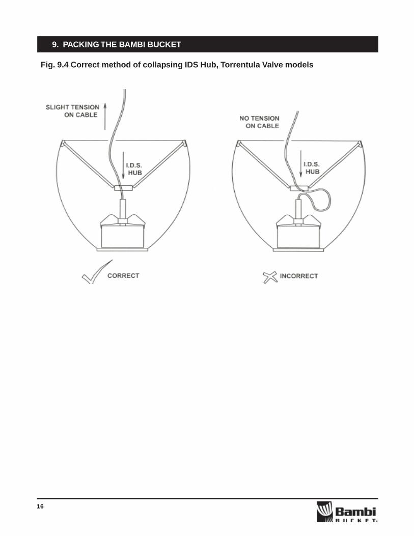
See fig. 9.4 for tips on the correct method ofcollapsing the IDS Hub, Torrentula Valve buckets
1) Collapse the Instant Deployment Systemby pushing the hub into the bucket. Keepslight tension on the actuator cable toavoid kinking the cable conduit at theconnection to the valve. Fig 9.4
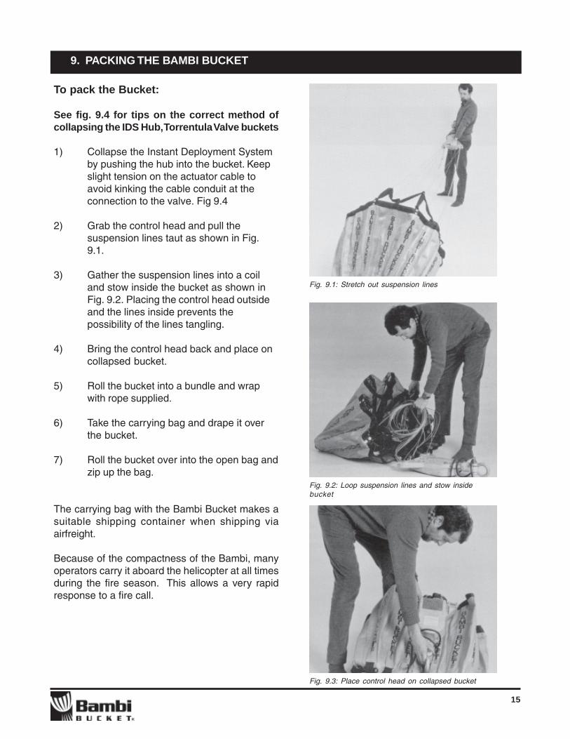
2) Grab the control head and pull thesuspension lines taut as shown in Fig.9.1.
3) Gather the suspension lines into a coiland stow inside the bucket as shown inFig. 9.2. Placing the control head outsideand the lines inside prevents thepossibility of the lines tangling.
4) Bring the control head back and place oncollapsed bucket.
5) Roll the bucket into a bundle and wrapwith rope supplied.
6) Take the carrying bag and drape it overthe bucket.
7) Roll the bucket over into the open bag andzip up the bag.
The carrying bag with the Bambi Bucket makes asuitable shipping container when shipping viaairfreight.
Because of the compactness of the Bambi, manyoperators carry it aboard the helicopter at all timesduring the fire season. This allows a very rapidresponse to a fire call.
Fig. 9.1: Stretch out suspension lines
Fig. 9.2: Loop suspension lines and stow insidebucket
Fig. 9.3: Place control head on collapsed bucket
16
9. PACKING THE BAMBI BUCKET
Fig. 9.4 Correct method of collapsing IDS Hub, Torrentula Valve models
9. PACKING THE BAMBI BUCKET

17
10. STORING THE BUCKET
We suggest that you follow these guidelines toensure the longevity of your Bambi Bucket:
1) Do not pile heavy objects on the bucket.
2) If foam has been used, wash the bucketprior to storing it.
3) Do not store a wet bucket. This will resultin the growth of mildew and corrosion ofaluminum and steel parts.
4) We recommend that you store the bucketin doors in an unfolded position, preferablyby suspending the main shackle from anoverhead hook. An alternative is to sus-pend the bucket upside down from itsbottom chain.
5) Before storing the bucket for an extendedperiod, perform the seasonal maintenaceprocedures as outlined in Section 11.
18
11. TORRENTULA VALVE SYSTEM MAINTENANCE & TROUBLESHOOTING
11.1 Introduction
The maintenance and repair of the Torrentula Valvesystem should only be undertaken by mechanics andtechnicians with a level of competencycommensurate with this class of product. Someproficiency with basic hand tools and knowledge ofbasic mechanical maintenance practices is essential.
If work on the Torrentula valve electrical controls isundertaken, further knowledge and experience inthe area of 28 volt DC electric circuitry is necessary.We have included in this manual a wiring diagram toassist operators in troubleshooting the electricalsystem. Before commencing work, we recommendthat technicians familiarize themselves with the wiringdiagram and the layout of the major components inthe system.
11.2 Description of the Torrentula valve andActuating Mechanism
System overview
The Torrentula Valve system consists of a variableflow sleeve valve mounted in the bottom of the BambiBucket shell. The valve is operated by an electro-mechanical actuator installed in the control head,located at the top junction point of the bucketsuspension lines. The control head also serves asthe main lifting member of the Bambi Bucket. Thevalve is linked to the actuator in the control head viaa fully-enclosed stainless steel pull cable. Theactuator provides the valve opening force, and theclosing forces are a combination of gravity, waterflow and constant force springs.
Valve operation: The Torrentula valve is essentiallya sleeve that moves vertically to expose an openannulus for the water in the bucket to flow through.The vertical position of the valve sleeve and the levelof water or “head” in the Bambi Bucket determinethe speed at which the water flows through. Thevertical position, or the valve opening, is fullycontrollable by the operator from 0 to 100% of theavailable valve travel.
The approximate transit time for the valve to movefrom the full “closed” position to the “full open” positionis 0.75 seconds. The fast transit time allows theoperator to distribute a single load of waterintoseveral full “open” drops. If desired, the operatormay also extend the length of a water drop byopening the valve partially.
Valve description
The Torrentula valve is mounted to a steel oraluminum ring that is bolted to the bottom of thebucket shell. This “base” ring supports pillars, at thetop of which a round aluminum plate or “top plate” isattached. To the center of the top plate is mountedan aluminum guide tube. The base ring, pillars, topplate, and guide tube form the “fixed” or rigid part ofthe valve on which the valve tube slides up and down.The large diameter valve tube has dual-durometerseals mounted top and bottom that prevent waterleakage when the valve is in the fully “closed”position. The sliding valve tube is supported at threepoints by engineered polymer bushings thatminimize sliding friction when the valve sleeve is intransit. The “top” bushing is mounted centrally in analuminum spider that is bolted to the valve sleeve,and the two “bottom” bushings are mounted in thelift bar assembly which doubles as the actuator cableattach point. Two of the support pillars in conjunctionwith the top guide tube serve to keep the valve sleevealigned with the fixed structure of the valve.
Actuator description
The actuator installed in the control head consistsof a motor/gear reducer unit to which an eccentriccable crank is mounted. The stainless steel actuatorcable is attached to the cable crank and serves toopen and close the Torrentula Valve by partial rotationof the crank in counter clockwise and clockwisedirections. The center of the gear reducer shaft iseccentric with the cable crank in order to providevariable leverage and speed to open the valveefficiently.

19
From the “closed” position, the cable crank hasmaximum leverage on the actuator cable, to providethe larger opening force to “crack” open the valve.The speed of opening the valve is increased by theprogressively longer leverage arm on the crank as itrotates counter-clockwise to the full “open” position.
The control head is designed to withstand moder-ate shock loads and temporary immersion in water.The front and rear covers are sealed to the controlhead body, and the electrical and a actuator cablespass into the control head via water-tight strainfittings.
11. TORRENTULA VALVE SYSTEM MAINTENANCE & TROUBLESHOOTING
11.3 Torrentula Valve electrical systemdescription
The Torrentula electrical system is designed to runon 28 volt DC electrical power supplied by the heli-copter, requiring a 30 amp circuit. The main compo-nents of the electrical system consist of: operator’scontrols, Printed Circuit card with controller logic, twopower relays, three position sensing limit switchesand a 28 volt dc actuator motor. The actuator switchesare enclosed in an operator’s control grip that alsohouses indicator lights for valve full “open” and valvefull “closed” indication. The printed circuit card andtwo power relays are contained in an enclosure towhich all the electrical connections are made.
The motor and limit switches are located in the controlhead. A 0.25 second delay is incorporated into thecontrol circuit to prevent sudden control reversalsfrom damaging the actuator motor while under load.Two limit switches in the control head act to stop theactuator motor when the full “open” and full “closed”limits are achieved. The actuator motor can bestopped at any point between full “open” and full“closed” by releasing the actuator switch. A third limitswitch in the control head acts as an over-travelsafety switch, to prevent damage to the actuatorcomponents in the event of failure of one of the otherlimit switches.

20
Seasonal inspectionsEvery 6 months
1) Remove any surface corrosion from aluminumparts with “Scotchbrite” or similar abrasive pad.
2) Thoroughly clean an dry the entire bucket andcontrol head, particularly if the bucket is beingput into storage.
3) Remove the rear cover and inspect the motor,gear reducer and electrical connections for cor-rosion and damage.
Preparation for storage(In addition to seasonal maintenance)
1) Perform all major repairs to the bucket andTorrentula Valve system before storage. This willensure operational readiness when the bucketis needed next
2) If the bucket is to be stored in a high-humidityenvironment, it is recommended that allaluminum and steel parts are given a light coatof corrosion preventative compound such asACF-50tm or WD-40tm
3) Place a small block of wood between the valvelift bar and base ring to lift the valve slightlyopen. This will prevent the seals from taking a“set” during storage.
It is highly recommended that the bucket bestored indoors when not in use. This willminimize deterioration of the bucketcomponents due to temperature change, UVlight, and atmospheric moisture.
4) The bucket should be hung upside down to dryout completely before being folded for storage.For maximum life, store the bucket in thedeployed position, away from direct sunlight. Thiswill ensure the bucket components remain dryfor the duration of storage.
11.4 Routine maintenance procedures
In addition to routine daily preflight inspections asoutlined in Section 2, Preflight Safety Check, thefollowing should also be performed when the bucketis in use:
Operational inspectionsEvery 20 hours or 3 days in continous use
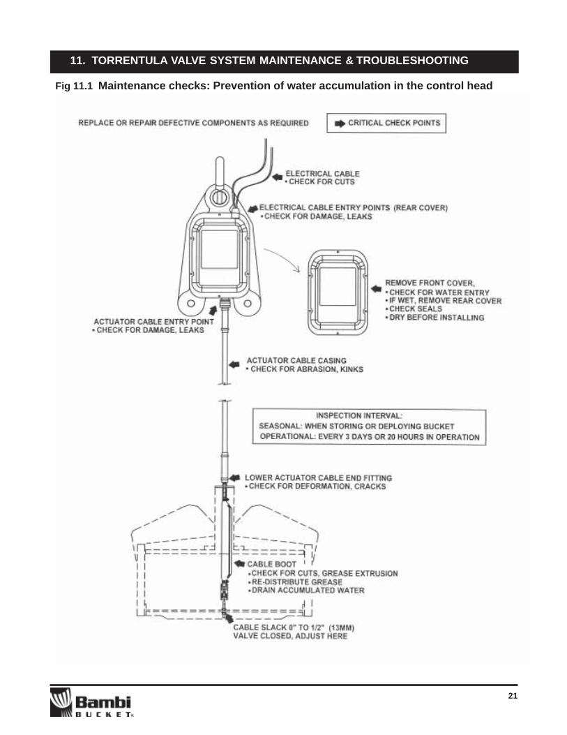
1) Check all parts of the control head for visibledamage or defects. Clean off all debris
2) Remove the front cover of the control head andcheck for water ingress and damage to internalcomponents. If water accumulation is apparent,remove the rear cover, wipe and allow to drycompletely. Inspect the cover seals for damageand re-secure the covers
See fig. 11.1 for detailed tips on how to preventmoisture accumulation in the control head.
3) Assess the function of the valve by manuallysliding the valve open from a fully closed position.Clean off debris
4) Inspect all electrical cables for damage5) Thoroughly inspect the top and bottom valve seals
for wear and damage.
11. TORRENTULA VALVE SYSTEM MAINTENANCE & TROUBLESHOOTING
21
11. TORRENTULA VALVE SYSTEM MAINTENANCE & TROUBLESHOOTING
Fig 11.1 Maintenance checks: Prevention of water accumulation in the control head

22
11. TORRENTULA VALVE SYSTEM MAINTENANCE & TROUBLESHOOTING
11.5 Unscheduled maintenance
Control head immersion in water
If the control head is repeatedly or continuallyimmersed in water during operation, it will benecessary to remove both front and rear coversof the control head to inspect for water ingress,even if the function of the control head does notappear to be impaired. If water is present insidethe control head it is necessary to thoroughly drythe components, with application of heat, forseveral hours before returning the unit to operation.
Actuator Cable replacement
Removal:1) Loosen and remove the bottom nut securing the bottom cable fitting to the valve lift bar2) Remove the two socket head allen screws securing the cable plate to the top slider tube3) Remove the control head front cover (the one
with the serial number plate)4) Remove cable guard plate5) Disconnect the top cable end from the cable
crank by removing the ¼” bolt6) Loosen the securing nuts at the top cable
adjuster bracket7) Remove the two bolts securing the cable guide
block8) Using water pump pliers, loosen the watertight
strain relief at the bottom of the control headhousing
9) Using a 12” crescent wrench, remove thewatertight fitting housing from the control headand pull the cable assembly free.
Installation:Installation is the reverse of removal, with thefollowing additional instructions:
1) Use waterproof pipe sealing compound orsilicone sealant to seal the threads of thewatertight strain relief housing
2) Tighten the jam nuts on the top cable fittingso that there are an equal number of threadsabove and below the nuts (in the middle ofavailable adjustment).
Actuator cable adjustment:1) Lay the bucket, suspension lines and control
head out in the deployed position with thesuspension lines pulled straight
2) Using aircraft power, cycle the valve actuatorto the “closed” position (confirm that the closedlight is “on”)
3) Adjust the two bottom nuts that secure thecable end to the valve lift bar so that there isslight tension it the cable. The valve seal shouldbe contacting the bottom plate, and you will beable to compress the valve seal slightly moreby pulling the lift bar towards the bottom of thebucket.
4) Cycle the valve open and closed several timesto ensure smooth movement and seating ofthe valve seals.
After several full load cycles a new cable willstretch approx. ¼” (6mm). A broken-in cable willhave a small amount of slack when felt above thelift bar. This is normal. However, excessiveamounts of slack will prevent full opening of thevalve, and if the cable is too tight, the valve maynot shut fully and will cause the valve to leak.
If insufficient adjustment is available on the cableend fitting, an additional 1/2”(13mm) adjustmentis available at the upper cable conduit fitting,located in the control head.
3) Check that the actuator cable rides about 1/16” to 1/8” (1.6mm – 3.2 mm) above the limitswitch cover when under tension. Adjust thetop cable fitting jam nuts to suit.

23
11. TORRENTULA VALVE SYSTEM MAINTENANCE & TROUBLESHOOTING
Problem Possible cause(s) Check/repair
Fig 11.2 Torrentula Valve Troubleshooting Chart
Check helicopter power supply for correctvoltage/polarity. Check circuit rating
Connect cables from Controller to controlhead, H2, H3
Ensure valve is free from obstruction bybucket shell when performing groundchecks.1) Adjust cable free length2) Adjust bottom bushings(See maintenance procedures for cablereplacement and bushing adjustment)1) Check limit switches for correctoperation. Replace as required2) Check power contactors for correctoperation. Replace as required
1) Check for obstruction of valve move-ment, cut or frayed electrical cables.Check rating of aircraft circuit breaker.Inspect condition of electrical components(See maintenance procedures for checkingelectrical components)2) Repair/replace actuator cable3) Replace actuator motor1) Repair/replace seal(s) as required2) Check cable free length and for correctvalve seating. (See maintenance proce-dures)Dry out control head. Check function ofcontrol head electrical components (seemaintenance procedures)Ensure control head seals are in goodcondition1) Repair/replace valve componentsas required2) Repair/replace control head componentsas required
1) Check the cable connections andcables for damage or corrosion2) Replace actuator motor
Incorrect connection toHelicopter power supply
Control cable, H2 notconnected.
Valve rubbing on inside ofBambi Bucket shell
1) Actuator cable free lengthis too short2) Valve bottom bushings arebinding on support rods
1) Limit switch failure ordamage2) Power contactor failure
1) Sudden short or circuitoverload2) Actuator cable failure3) Actuator motor failure
1) Valve seal or seals aredamaged2) Valve is not closing fully
Control head electricalcomponents damaged due tocontact with water
1) Bent or broken valvecomponents
2) Damaged or broken controlhead components
1) Poor electrical connection2) Actuator motor faulty, mayoccur if motor is immersed inwater
Valve will not work when firstconnected to helicopter
Valve will not work when firstconnected. “Open” and “closed”indicator lights both on
Valve moves slowly or roughlywhen tested
Valve does not close fully
Valve operates normally and thenstops in full “open” or full “closed”position
Valve operates normally and thensuddenly fails to operate
Valve leaks
Valve fails to operate after controlhead immersion in water
Valve fails to operate after suddenimpact with object or ground
Control head actuator motoroperates slowly or intermittently

24
11. TORRENTULA VALVE SYSTEM MAINTENANCE & TROUBLESHOOTING
Seal repair and replacement
Field repairs
If a top or bottom valve seal has been damaged, itmay be possible to perform a sufficient temporaryrepair, given that the damage is limited to small tearsor rips.1) If the area to be repaired is wet, dry thoroughly
with forced hot air2) Position the two sides of the tear or rip so that
the edges line up3) Apply a small quantity of cyanoacriliate adhe-
sive (SEI Industries will supply Locktite 495,other common Brands include Super Glue,Crazy Glue, Zap!, etc.) along the tear and pressgently together until a bond is achieved. Pleaseobserve the warning labels on the adhesivecontainer. See Fig. 11.2
4) If the edge of the glue joint is rough or protrudesabove the surface of the seal, it may be dressedlightly with medium-grit sandpaper.
Seal replacement is recommended if repairs fail torestore full seal function
Top seal replacement
NOTE: If the replacement valve seal comesprejoined, the seal may be replaced more easily byremoving the top spider assembly and springbrackets as one peice. If the seal comes as anunjoined length follow steps 1 through 9 below:
1) Prop the valve tube slightly open by pulling upon the valve spider and placing a block of woodbetween the spider and the top plate
2) Remove the four seal retaining clips along thetop edge of the valve
3) Pull the seal off the retaining ring, cut the sealand remove it from the valve
4) Position the new length of valve seal on the sealretaining ring. It will be necessary to “push” orcompress the seal as you install it on theretaining ring. This will ensure the new seal sitstight on the ring and will not slip off.
5) Check that the ends of the seal are pushedtogether snugly when the seal is fully seatedon the ring. If they are too tight, trim the sealback a bit with a sharp knife
6) When satisfied, pull the free ends of the sealseveral inches inward from the seal ring
7) Carefully mate the two ends of the seal. If theseal ends are not fully square, take the time totrim them, using a very sharp knife.
8) Apply Locktite 495 to one end of the seal andcarefully mate the seal ends to make a nearlyseamless joint. Apply pressure until a bond ismade - approx. 60 seconds. The joint may bedressed with medium grit sandpaper to re-move roughness
9) Push the seal fully onto the seal ring andreinstall the seal retaining clips.
Fig 11.3 Joining Seal Ends
25
11. TORRENTULA VALVE SYSTEM MAINTENANCE & TROUBLESHOOTING
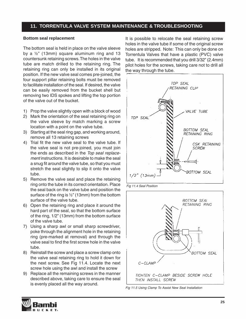
Bottom seal replacement
The bottom seal is held in place on the valve sleeveby a ½” (13mm) square aluminum ring and 13countersunk retaining screws. The holes in the valvetube are match drilled to the retaining ring. Theretaining ring can only be installed in its originalposition. If the new valve seal comes pre-joined, thefour support pillar retaining bolts must be removedto facilitate installation of the seal. If desired, the valvecan be easily removed from the bucket shell butremoving two IDS spokes and lifting the top portionof the valve out of the bucket.
1) Prop the valve slightly open with a block of wood2) Mark the orientation of the seal retaining ring on
the valve sleeve by match marking a screwlocation with a point on the valve tube.
3) Starting at the seal ring gap, and working around,remove all 13 retaining screws
4) Trial fit the new valve seal to the valve tube. Ifthe valve seal is not pre-joined, you must jointhe ends as described in the Top seal replace-ment instructions. It is desirable to make the seala snug fit around the valve tube, so that you muststretch the seal slightly to slip it onto the valvetube.
5) Remove the valve seal and place the retainingring onto the tube in its correct orientation. Placethe seal back on the valve tube and position thesurface of the ring is ½” (13mm) from the bottomsurface of the valve tube.
6) Open the retaining ring and place it around thehard part of the seal, so that the bottom surfaceof the ring, 1/2” (13mm) from the bottom surfaceof the valve tube.
7) Using a sharp awl or small sharp screwdriver,poke through the alignment hole in the retainingring (pre-marked at removal) and through thevalve seal to find the first screw hole in the valvetube.
8) Reinstall the screw and place a screw clamp ontothe valve seal retaining ring to hold it down forthe next screw. See Fig 11.4. Locate the nextscrew hole using the awl and install the screw
9) Replace all the remaining screws in the mannerdescribed above, taking care to ensure the sealis evenly placed all the way around.
It is possible to relocate the seal retaining screwholes in the valve tube if some of the original screwholes are stripped. Note: This can only be done onTorrentula Valves that have a plastic (PVC) valvetube. It is recommended that you drill 3/32” (2.4mm)pilot holes for the screws, taking care not to drill allthe way through the tube.
Fig 11.4 Seal Position
Fig 11.5 Using Clamp To Assist New Seal Installation
26
11. TORRENTULA VALVE SYSTEM MAINTENANCE & TROUBLESHOOTING
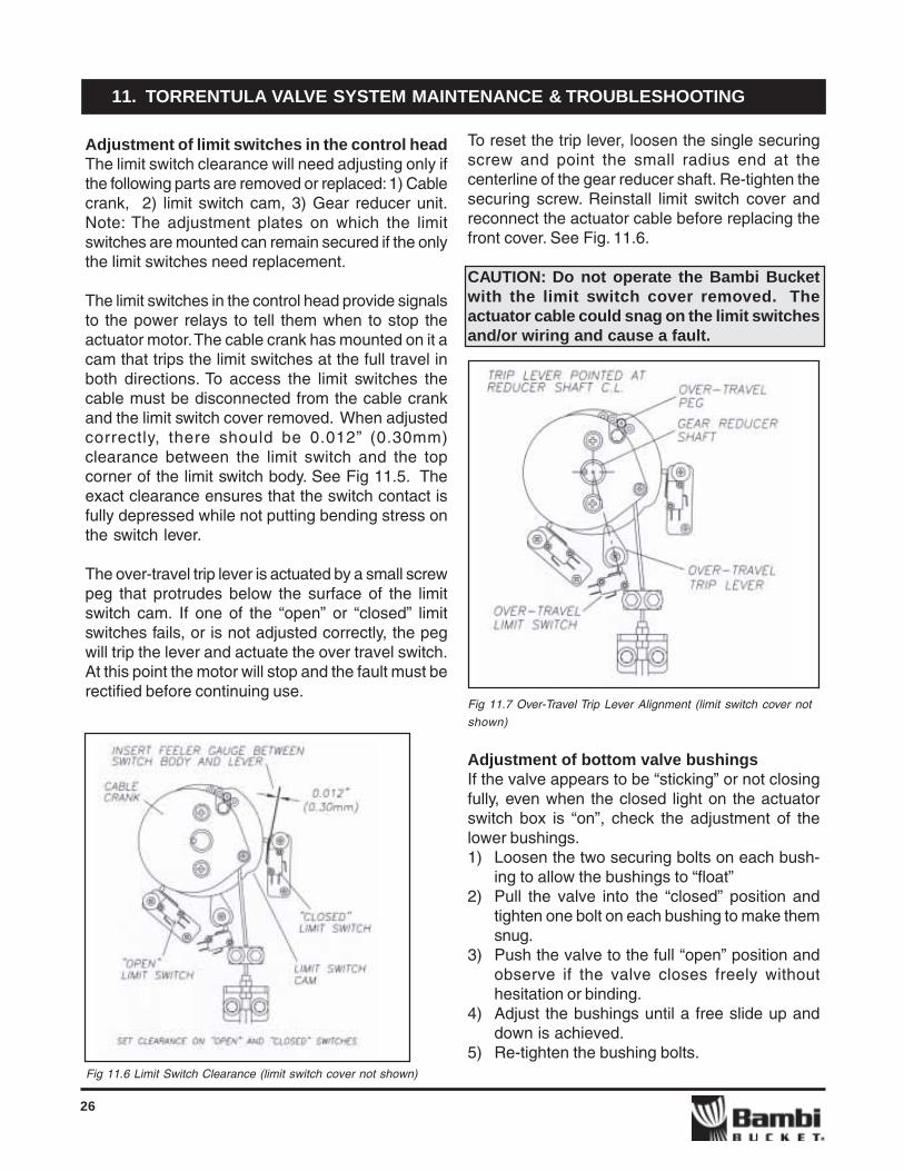
To reset the trip lever, loosen the single securingscrew and point the small radius end at thecenterline of the gear reducer shaft. Re-tighten thesecuring screw. Reinstall limit switch cover andreconnect the actuator cable before replacing thefront cover. See Fig. 11.6.
CAUTION: Do not operate the Bambi Bucketwith the limit switch cover removed. Theactuator cable could snag on the limit switchesand/or wiring and cause a fault.
Fig 11.7 Over-Travel Trip Lever Alignment (limit switch cover not
shown)
Adjustment of bottom valve bushingsIf the valve appears to be “sticking” or not closingfully, even when the closed light on the actuatorswitch box is “on”, check the adjustment of thelower bushings.1) Loosen the two securing bolts on each bush-
ing to allow the bushings to “float”2) Pull the valve into the “closed” position and
tighten one bolt on each bushing to make themsnug.
3) Push the valve to the full “open” position andobserve if the valve closes freely withouthesitation or binding.
4) Adjust the bushings until a free slide up anddown is achieved.
5) Re-tighten the bushing bolts.
Adjustment of limit switches in the control headThe limit switch clearance will need adjusting only ifthe following parts are removed or replaced: 1) Cablecrank, 2) limit switch cam, 3) Gear reducer unit.Note: The adjustment plates on which the limitswitches are mounted can remain secured if the onlythe limit switches need replacement.
The limit switches in the control head provide signalsto the power relays to tell them when to stop theactuator motor. The cable crank has mounted on it acam that trips the limit switches at the full travel inboth directions. To access the limit switches thecable must be disconnected from the cable crankand the limit switch cover removed. When adjustedcorrectly, there should be 0.012” (0.30mm)clearance between the limit switch and the topcorner of the limit switch body. See Fig 11.5. Theexact clearance ensures that the switch contact isfully depressed while not putting bending stress onthe switch lever.
The over-travel trip lever is actuated by a small screwpeg that protrudes below the surface of the limitswitch cam. If one of the “open” or “closed” limitswitches fails, or is not adjusted correctly, the pegwill trip the lever and actuate the over travel switch.At this point the motor will stop and the fault must berectified before continuing use.
Fig 11.6 Limit Switch Clearance (limit switch cover not shown)

27
11. TORRENTULA VALVE SYSTEM MAINTENANCE & TROUBLESHOOTING
11.6 Electrical controls troubleshooting
Troubleshooting faults in the electrical system willrequire at least a basic knowledge of DC electricaltheory and some understanding of the function ofswitches, relays, and electric motors. Someexperience in the art of troubleshooting is essential.For these reasons, we highly recommend that onlyqualified mechanics and or electrical techniciansattempt to repair the electrical system without theassistance of technical support from SEI Industries.
Electrical faults are usually simple and the result ofa discontinuity in electrical flow. The most likely placeto start is an inspection of all external electricalconduits, checking for breaks in wires or tell-taledamage. Also, check connectors for signs ofdamage or corrosion. If all external appearancesare normal, then an assessment of the function ofeach component may be required.
For troubleshooting we recommend you have onhand the following tools:1) Electrical Multi-meter for checking voltage,
resistance and continuity2) Some form of 24-28 volts DC power supply
(other than the aircraft power supply) forchecking individual component function.
Warning: Observe all reasonable precautions whentesting components with live DC power. Failure todo so could result in serious personal injury. Useextreme care when performing any disassemblyand re-assembly of the electrical system. Allconnections as shown on the wiring diagram arenon-negotiable - any missed connections will causefailure of the system in some way. Errors in wiringcan cause an infinite array of malfunctions, frombenign to disastrous – use caution and double checkyour work.
Keep the wiring diagram handy at all times whenworking on the electrical system. Before performingany checks, be sure to understand the function ofeach component within the system.
Electrical component function checks
Circuit breakersLocation: right hand side ofController box. Theplunger should be “in” for operation. If the breakerhas “tripped” and the plunger is “out”, immediatelydisconnect power and perform the function checkson each component in isolation. Check forcontinuity of the circuit breaker with the plunger “in”.
Power relays (aka contactors)Location: Right hand side of junction box, with lidoff, looking down. With power off, there should begood continuity (very low resistance) across theNC terminals. Check the resistance across the coilterminals with plug J4 removed from the circuitboard. The Resistance should be approximately 50ohms. With the relay isolated, apply power acrossthe coil contacts – if it is functioning correctly therewill be an audible “click”. With power across therelay coil there should be continuity across the NOterminals.
Caution: It is recommended that the actuator cablebe disconnected from the cable crank whenperforming function checks of the control headcomponents. This will eliminate the possibility ofdamage the actuator cable and or valve in the eventof a malfunction or mis-adjustment.
28
Printed circuit card
Location: rear of enclosure.Assessment of the printed circuit board is limited toa visulal inspection. Look for any obviousoverheated components or burnt solderconnections. If available, swap the suspect boardwith a known functioning one.
Limit switches (aka micro-switches)
Location: inside front cover of control headWith power off, the limit switch lever extended andthe leads disconnected, there should be continuityacross the NC and COM terminals. When the leveris depressed, there should be continuity betweenthe NO and COM terminals.
11. TORRENTULA VALVE SYSTEM MAINTENANCE & TROUBLESHOOTING
Actuator motor
Location: inside back cover of control headRemove the motor from the gear reducer unit byundoing the two securing screws and applyinggently prying force on either side of the motor.Apply power directly to the motor leads. The motorshould run smoothly with no grinding or rough-ness.
Caution: Applying power directly to the motor leadswhile it is still attached to the reducer will causeactuation of the over-travel trip lever, and willrequire re-setting (see maintenance procedures,Section 11.5, Adjustment of limit switches incontrol head)

29
Temporary patches using materials such as sili-cone sealant, roofing plastics etc. may spoil thesurface for future proper welded or heat-appliedpermanent repairs. A good quick way to repair thebucket is to apply a stitched on or bolted on patch.
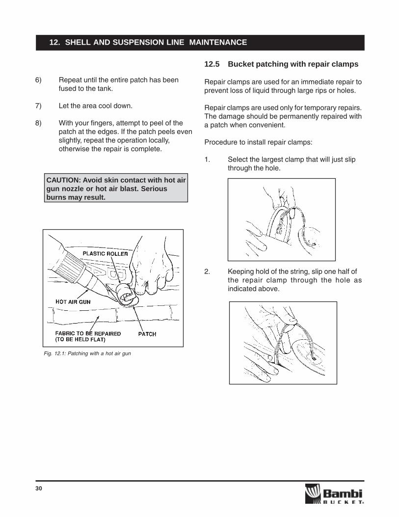
12.4 Bucket patching with a hot air gun
Tools and Materials Required:• SEI patching kit.• One plastic hand held roller• One hot air gun, Steinel HL 1800E, or
equivalent (120V-1500W; 200 to 1100° F;450 Lit. per min.)
• One wide surface nozzle• T.H.F. solvent or equivalent
Procedure:1) In a well-ventilated location, clean the area
to be repaired with T.H.F. or any othersolvent compatible with the fabric. SEI alsorecommends Isopropyl alcohol for cleaningthe damaged area.
2) Mount a wide surface air nozzle on the hotair gun so as to direct the heat flow in alarge pattern.
3) Turn the power ON, and set the tempera-ture in the low range first to let the hot airgun warm up. Increase the temperature asrequired during the operation.
CAUTION: Do not overheat or blacken thefabric.
4) Starting from the centre of the patch helddown by the roller as in Fig. 12, concentratethe heat flow equally to patch and fabric.Start applying a light pressure with theroller when the fabric starts melting.DO NOT OVERHEAT.
5) Roll the patch down to fuse it to the tankfabric, moving roller and gunsimultaneously.
12. SHELL AND SUSPENSION LINE MAINTENANCE
Available from SEI Industries is the new BambiBucket Repair Assessment Manual. This manualis intended to provide the user with information thatwill allow for the proper repair assessmentevaluation of the Bambi Bucket. Contact SEIIndustries for a copy, or download one from the SEIwebsite.
12.1 Suspension line replacement
Suspension lines should be replaced whenever theydisplay noticeable kinking or fraying. Factoryreplacement lines can be ordered with or withoutthe end thimbles swaged on. The incomplete linescan be swaged directly onto the fabric M-straps(as original equipment). Complete lines are attachedto the M-straps with shackles. When usingshackles, ensure that they are secured with a tiewrap or lock-wire before using bucket.
12.2 M-strap replacement
Replace the M-straps if they become noticeablyworn. M-straps can be repaired, if frayed, by meltingthe fray with a lighter to stop the fray from spreading.The length of the M-straps is critical to properfunctioning of the Bambi bucket and we recommendthat you replace worn straps with factory equipment.There are three types of straps: fabric long, fabricshort and chain. Fabric shorts are used for thevertical straps, fabric longs are used for the diagonalstraps and chains are used in the front of the largerBambi Buckets where abrasion due to dragging canoccur.
When replacing straps, do one set at a time to avoidconfusion. Cut off the old straps from the shackleand untie them from the top of the bucket shell.Attach replacement straps per the originals. To avoidunnecessary wearing, it is important that thestrapping be bound with tie wraps where it attachesto the shackles (observe originals). Secure theshackles with a tie wrap.
12.3 Bucket patching
30
Fig. 12.1: Patching with a hot air gun
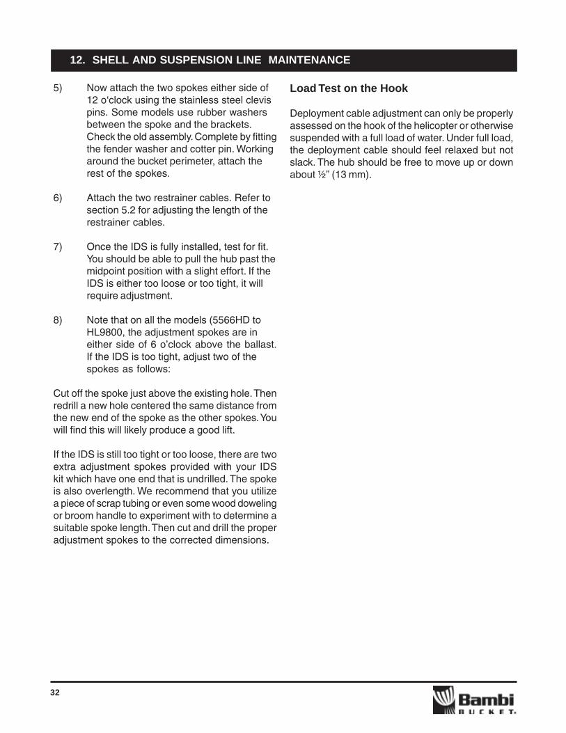
12.5 Bucket patching with repair clamps
Repair clamps are used for an immediate repair toprevent loss of liquid through large rips or holes.
Repair clamps are used only for temporary repairs.The damage should be permanently repaired witha patch when convenient.
Procedure to install repair clamps:
1. Select the largest clamp that will just slipthrough the hole.
2. Keeping hold of the string, slip one half ofthe repair clamp through the hole asindicated above.
12. SHELL AND SUSPENSION LINE MAINTENANCE
6) Repeat until the entire patch has beenfused to the tank.
7) Let the area cool down.
8) With your fingers, attempt to peel of thepatch at the edges. If the patch peels evenslightly, repeat the operation locally,otherwise the repair is complete.
CAUTION: Avoid skin contact with hot airgun nozzle or hot air blast. Seriousburns may result.

31
3. Pull the bolt up through the hole. Turn ituntil the clamp lines up with the hole.
4. Place the top of the clamp over the bolt
5. Tighten the nut by hand
CAUTION: Tightening the nut with toolsmay break the bolt away from the lowerclamp.
Leaving the string on makes it easier to removethe repair clamp when placing a permanent patchon the bucket.
This procedure is to be used for repairs whenhole(s) or small cuts occur. The size of the cut orhole will determine the size of the sealing clamp touse. Clamps may not form a leakproof repair if usedon or over a seam. Sealing clamps are availablefrom SEI Industries Ltd.
For a cut or hole up to 2” (5 cm) use a 3” (7.6 cm)clamp.
For a cut or hole up to 4” (10 cm), use a 5”(12.7cm) clamp.
For a cut or hole up to 6” (15 cm), use a 7.5” (19cm) clamp.
Slip the inside clamp through the cut in the bucketand rotate it until it is parallel with the cut.
Centre both clamps over the cut, tighten wing nutwith fingers and then, if necessary, lightly tightenwith pliers. The protruding cord may be cut off ifdesired. Overtightening can deform the clam andcause leaks.
12.6 IDS hub/spokes replacement
There are three different IDS hub sizes. The smallhub fits Bambi Bucket Models 6072 through 1821.The medium hub is found on Models 2024 through5566 and the large hub is found on Models 6578and larger.
You can purchase the IDS system either as acomplete kit or as individual pieces as required. Wewill describe here how to replace the entireassembly.
1) Start by removing the old IDS including theshell brackets and the old restrainer cablebrackets. You will have to disconnect thetrip line from the valve or control head sinceit passes through the hub.
2) For reassembly, first install the new shellbrackets. Install bolts through the bucketshell. Next, fit the fabric wear strips onto thebolts. Then fit the brackets to the bolts, andinstall and tighten the Nylock nuts.
3) Now install the two restrainer cablebrackets. One is found below the ballast andthe other is 6 o‘clock directly opposite. Nowear strips are required for the restrainercable brackets.
4) With the ballast oriented at the 6 o‘clockposition, rotate the IDS assembly so thatthe deployment cable faces upward and isat the 3 o‘clock (as it should be on allmodels 5566HD through HL9800).
12. SHELL AND SUSPENSION LINE MAINTENANCE
32
5) Now attach the two spokes either side of12 o‘clock using the stainless steel clevispins. Some models use rubber washersbetween the spoke and the brackets.Check the old assembly. Complete by fittingthe fender washer and cotter pin. Workingaround the bucket perimeter, attach therest of the spokes.
6) Attach the two restrainer cables. Refer tosection 5.2 for adjusting the length of therestrainer cables.
7) Once the IDS is fully installed, test for fit.You should be able to pull the hub past themidpoint position with a slight effort. If theIDS is either too loose or too tight, it willrequire adjustment.
8) Note that on all the models (5566HD toHL9800, the adjustment spokes are ineither side of 6 o’clock above the ballast.If the IDS is too tight, adjust two of thespokes as follows:
Cut off the spoke just above the existing hole. Thenredrill a new hole centered the same distance fromthe new end of the spoke as the other spokes. Youwill find this will likely produce a good lift.
If the IDS is still too tight or too loose, there are twoextra adjustment spokes provided with your IDSkit which have one end that is undrilled. The spokeis also overlength. We recommend that you utilizea piece of scrap tubing or even some wood dowelingor broom handle to experiment with to determine asuitable spoke length. Then cut and drill the properadjustment spokes to the corrected dimensions.
Load Test on the Hook
Deployment cable adjustment can only be properlyassessed on the hook of the helicopter or otherwisesuspended with a full load of water. Under full load,the deployment cable should feel relaxed but notslack. The hub should be free to move up or downabout ½” (13 mm).
12. SHELL AND SUSPENSION LINE MAINTENANCE

33
13. WARRANTY
SEI Industries Ltd. (The Company) agrees to granta Warranty for a period of one year from the date ofpurchase of Bambi Bucket systems on the followingconditions:
a) The Company’s sole obligation under thisWarranty is limited to repairing or replacing,at the Company‘s sole discretion, anyproduct proved to be defective.
b) The Company’s products are notguaran teed for any specific length of timeor measure or service, but are warrantedto be free from defects in workmanship andmaterial for a period of one year to theoriginal purchaser.
c) To the extent allowable under applicablelaw, the Company’s liability for consequen-tial and incidental damages is expresslydisclaimed. The Company’s liability in allevents is limited to, and shall not exceed,the purchase price paid.
d) This Warranty is granted to the originalpurchaser of Bambi Bucket systems anddoes not extend to a subsequent purchaseror assignee.
e) The Company must receive notification inwriting of any claims of Warranty from theoriginal purchaser who must give details ofthe claimed defect in the product.
f) Where the original purchaser is claimingunder Warranty, the product must bereturned to the Company for inspection withall transportation and duty charges prepaid.
g) The Warranty does not extend to anyproduct that has been accidentallydamaged, abraded, altered, punctured,abused, misused, or used for a purposewhich has not been approved by theCompany.
h) This Warranty does not apply to anyacessories used with the product that arenot supplied by the Company, and anyWarranty on such accessories must berequested from the manufacturer or dealerof the accessories.
i) In the event the original purchaser does notgive notice of a Warranty claim within oneyear of the original purchase of the product,it is understood that the purchaser haswaived the claim for Warranty and thepurchaser and/or any subsequentpurchaser must accept the condition of theproduct as it may be, without Warranty.
j) Any technical information supplied by theCompany regarding the product is not acondition of Warranty but rather isinformation provided by the Company to thebest of its knowledge.
k) There are no implied warranties nor is thereany Warranty that can be assumed fromany representation of any person, exceptthe Company itself.
Exclusions
l) This Warranty is void if the product is notinstalled, used and/or maintained inaccord ance with the Field Manual suppliedby SEI Industries Ltd.
m) All Bambi Buckets are designed andmanufactured with substantial safetymargins. It is the responsibility of the userto ensure that the bucket is maintained to asafe standard.

34
14. SPECIFICATIONS
Note: These are guidelines only.The helicopter operator must make the decision as to which model of Bambi Bucket is appropriate.
Torrentula Valve Bucket Specifications
Torrentula Model Gross Wt (lbs/Kg) Suggested Helicopters
BBT 2732 2845/1295 Bell 204, Sikorsky S-76A, S-76B, MD Explorer
BBT 3542 3660/1665 Augusta AB 212 & AB 412, Bell 204B, 205, 212 & 412 SP, Huey UH-1H
BBT 4453 4580/2080 Aerospatiale Puma, California/Sikorsky S58T, W3 Sokol
BBT 5566 5777/2600 Aerospatiale Puma, Bell 214B & 214 St., Kawasaki- Boeing KV107, Sikorsky UH 60-A (Black Hawk), MI-8, MI-17
BBT 6578 6818/3068 MI-26
BBT 7590 7747/3486 Agusta AS-61N-1, Aerospatiale Super Puma & Super Frelon, Sikorsky S-61
BBT HL5000 11362/5112 Boeing Vertol CH46, EH101, MI-38, KA-32
BBT HL7600 17087/7690 Sikorsky S-64 Skycrane
BBT HL9800 22152/9968 Boeing Vertol 234/CH47 (Chinook), Sikorsky CH53E
ModelUSG IMP. GAL. Liters Lb. Kg. Lb. Kg
BBT 2732 315 265 1190 2845 1295 183 83 BBT 3542 410 345 1555 3660 1665 197 89 BBT 4453 520 435 1960 4580 2080 217 98 BBT 5566 HD 640 535 2400 5777 2600 425 191 BBT 5870 HD 680 566 2574 6124 2778 451 204 BBT 6578 HD 760 635 2850 6818 3068 476 214 BBT 7590 HD 880 735 3300 7747 3486 495 225 BBT HL5000 1300 1080 4900 11362 5112 510 230 BBT HL7600 2000 1665 7570 17087 7690 585 263 BBT HL9800 2600 2165 9840 22152 9968 650 292
Capacity Gross Weight Empty Weight

35
15. CONTROL HEAD PARTS ALL MODELS
Figure 15.1 Control Head Parts, ALL Models

36
Table 15.1 Control Head Parts List, ALL Models
15. CONTROL HEAD PARTS ALL MODELS
Item # Part # Description Qty.
209 FTAG-005 SHACKLE, 5566 TO 9800 1208 CABLE GUARD STAND-OFF, 15/16" LG. 3205 SILICONE SEALANT AS REQ.204 FRA 002 RIVET, SELF SEALING, 1/8" 4203 FSN 250 M/S COVER STAND-OFF, 13/16" LG. 3202 MOTOR SHAFT KEY, 3/16" SQ. X 1" LG. 1201 BAD1652 GEAR MOTOR 1116 FBSC 010406 HEX HD CAP SCREW 2115 FWS 0504 SPLIT LOCK WASHER, 1/4" ID 19114 FWS 0100 PLAIN WASHER, #4 ID 6113 FWN 0303 PLAIN WASHER, NYLON, 3/16" ID 1112 FWS 060306 PLAIN WASHER, 3/16" ID, 3/4" OD 3111 FWS 0204 PLAIN WASHER, 1/4" ID, 5/8" OD 7110 CSK PHIL SCREW, 1/4-20 X 1-1/4" LG 7109 FBSC 020005 SOC HD CAP SCREW, 4-40 X 5/8" 6108 FPPC 030204 HEX DRIVE CSK SCREW, 8-32 X 1/2" 1107 BADZ 46107 HEXDRIVE SET SCREW, 1/4-20 X 3/8" 2106 FBSC 040305 PAN PHIL SCREW, 10-24 X 5/8" 15105 FBSC 040314 CSK PHIL SCREW, 10-24 X 2-1/4" 3104 FBSC 010410 HEX HD CAP SCREW, 1/4-20 X 1-1/4" 3103 FBSC 010416 HEX HD CAP SCREW, 1/4-20 X 1-3/4" 2102 FBSC 010406 HEX HD CAP SCREW, 1/4-20 X 3/4" 14101 FBPC 010610 HEX HD BOLT, 3/8-16 X 1" 320 SPECIFY MODEL, S/N CABLE CRANK SHIM 119 BAB 334 CRANK SPACER 118 BAB 333 CABLE GUARD PLATE 117 LB 001E S/N PLATE 116 BAB 262 CABLE BRACKET 115 BAB 261 CABLE GUIDE PLATE 114 BAB 260 CABLE GUIDE 113 SPECIFY MODEL, S/N MICROSWITCH COVER 112 BAB 257 OVERTRAVEL TRIP LEVER 111 BAB 256 MICROSWITCH MOUNT PLATE 210 BAB 255 MICROSWITCH CAM 19 BAB 254 CABLE CRANK 18 BB0571M CAST MOTOR COVER 17 BAD2827 COVER 0-RING SEAL 26 BB0570M CAST FRONT COVER 15 SPECIFY MODEL, S/N FRONT COVER STAND OFF 14 SPECIFY MODEL, S/N HEAD PLATE 13 SPECIFY MODEL, S/N CONTROL CABLE ASSEMBLY 12 BB 597 HEAD ASSY. MODELS 2732 - 44531 BB 596 HEAD ASSY. MODELS 5566 - HL9800
37
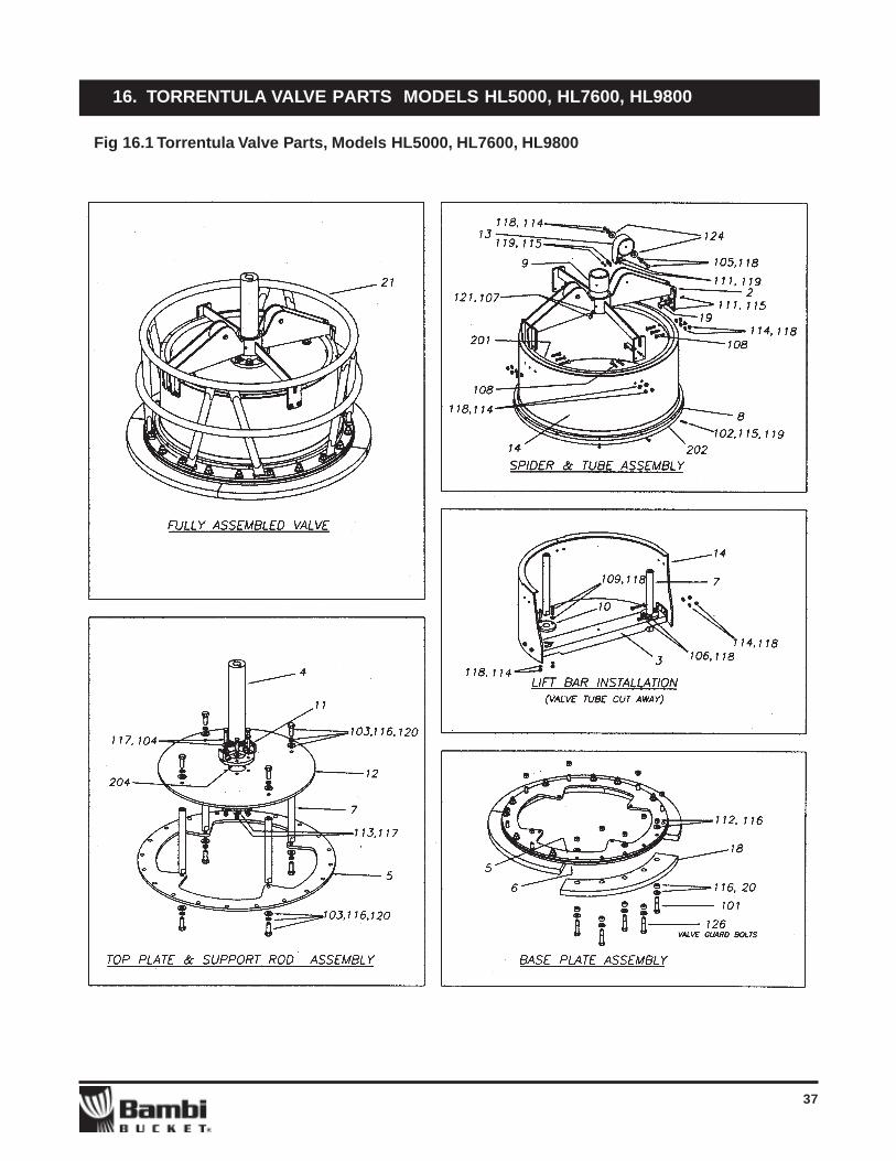
16. TORRENTULA VALVE PARTS MODELS HL5000, HL7600, HL9800
Fig 16.1 Torrentula Valve Parts, Models HL5000, HL7600, HL9800

38
16. TORRENTULA VALVE PARTS MODELS HL5000, HL7600, HL9800
Table 16.1 Torrentula Valve Parts List, Models HL5000, HL7600, HL9800
Item # Part # Description Qty.209 SILICONE SEALANT AS REQ.208 PP 020 SEALANT TAPE 14 FT.205 BAD 316205 ROD - BENT TO 27" 1204 PLA 001A 2" NPT FLANGE 1202 BAD 316202 BOTTOM SEAL, CUT 84.75" LG. 1201 BAD 316201 TOP SEAL, CUT 79.75" LG. 1126 HEX HD BOLT, 1/2UNC X 3” 8125 FWS 0104 FENDER WASHER, 1/4 ID X 3/4 OD 4124 FWS 0304 THICK WASHER, 1/4 ID X 1/8” THK. 4123 FWS 060306 FENDER WASHER, 4122 PANPHIL SCREW, 10-24 X 3/8” 4121 FWS 0504 SPLIT LOCK WASHER, 1/4 ID 2120 FWP 0508 SPLIT LOCK WASHER, 1/2 ID 8119 FWS 0203 PLAIN WASHER, 3/16 ID 8118 FWS 0204 PLAIN WASHER, 1/4 ID 24117 FWP 0106 PLAIN WASHER, 3/8 ID 12116 QTXNOW40 PLAIN WASHER, 1/2 ID 40115 FNSC 0203 NYLOC NUT, 10-24 21114 FNSC 0204 NYLOC NUT, 1/4UNC 20113 FNPC 0206 NYLOC NUT, 3/8UNC 6112 FNPC 0208 NYLOC NUT, 1/2UNC 20111 FBSC 040306 PAN PHIL SCREW, 10-24 X 3/4” 8110 FBSC 020406 SOC HD. CAP SCREW, 1/4UNC X 3/4” 2109 FBSC 020412 SOC HD. CAP SCREW, 1/4UNC X 1-1/4” 4108 FBSC 030410 CSK SOC HD. CAP SCREW, 1/4UNC X 1” 10107 FBSC 010406 HEX HD. BOLT, 1/4UNC X 1/2” 2106 FBSC 0101410 HEX HD. BOLT, 1/4UNC X 1” 4105 FBSC 010430 HEX HD. BOLT, 1/4UNC X 3” 2104 FBPC 010616 HEX HD. BOLT, 3/8UNC X 1-1/2” 6103 FBPC 010814 HEX HD. BOLT, 1/2UNC X 1-1/2” 8102 FBSC 030312 CSK PHIL SCREW, 10-24 X 1-1/4” 13101 FBPC010824 HEX HD. BOLT, 1/2UNC X 2-1/2” 1221 BAD 357 VALVE GUARD ASSEMBLY 120 RMA 6020 SPACER 2019 BAB 207 TOP SEAL CLIP 818 BAB 328 BUMPER BLOCK 417 BAB 162 LIFT BAR SHIM AS REQ.16 BAB 161 LARGE SPIDER SHIM AS REQ.15 BAB 161 SMALL SPIDER SHIM AS REQ.14 BAD 324 VALVE TUBE 113 BAB 158 SPRING ASSEMBLY 212 BAB 327 TOP PLATE 111 BAB 156 SPRING BRACKET 210 BAB 155 BOTTOM BUSHING 29 BAB 154 TOP SLIDER BUSHING 18 BAB 325 BOTTOM SEAL HOOP 17 BAB 150 SUPPORT ROD 46 BAB 323 CLAMP RING 15 BAB 322 BASE RING 14 BAB 144 SLIDER PIPE ASSEMBLY 13 BAB 321 LIFT BAR ASSEMBLY 12 BAD 317 LIFT SPIDER ASSEMBLY 11 BAD 316 VALVE ASSEMBLY

39
17. TORRENTULA VALVE PARTS MODELS 5566, 5870, 6578, 7590
Figure 17.1 Torrentula Valve Parts, Models 5566, 5870, 6578, 7590

40
17. TORRENTULA VALVE PARTS MODELS 5566, 5870, 6578, 7590
Table17.1 Torrentula Valve Parts List, models 5566, 5870, 6578, 7590
209 CLEAR SILICONE SILICONE SEALANT208 PP 020 SEALANT 14'205 BAD 316205 ROD - BENT TO 27" 1204 PLA 001A 2" NPT FLANGE 1202 BAD 134202 BOTTOM SEAL, CUT 76" LG. 1201 BAD 134201 TOP SEAL, CUT 69" LG. 1127 HEX HD. BOLT, 1/2UNC X 3” 8126 FSS 060212 PAN PHIL TAPPING SCREW, #8 X 5/8” 16125 FWS 0104 FENDER WASHER, 1/4 ID, 3/4 OD 4124 FWS 0304 THICK WASHER, 1/4 ID X 1/8” THK. 4123 FWS 060306 FENDER WASHER, 3/16 ID, 3/4 OD 4121 FWS 0504 SPLIT LOCK WASHER, 1/4 ID 2120 FWP 0508 SPLIT LOCK WASHER, 1/2 ID 8119 FWS 0203 PLAIN WASHER, 3/16 ID 4118 FWS 0204 PLAIN WASHER, 1/4 ID 24117 FWP 0106 PLAIN WASHER, 3/8 ID 12116 FWP 0108 PLAIN WASHER, 1/2 ID 40115 FNSC 0203 NYLOC NUT, 10-24 4114 FNSC 0204 NYLOC NUT, 1/4UNC 20113 FNPC 0206 NYLOC NUT, 3/8UNC 6112 FNPC 0208 NYLOC NUT, 1/2UNC 20111 FBSC 040306 PAN PHIL SCREW, 10-24UNC X 3/4” 4110 FBSC 020406 SOC HD. CAP SCREW, 1/4UNC X 3/4” 2109 FBSC 020412 SOC HD. CAP SCREW, 1/4UNC X 1-1/4” 4108 FBSC 030410 CSK SOC HD. CAP SCREW, 1/4UNC X 1-1/2” 10107 FBSC 010406 HEX HD. BOLT, 1/4UNC X 1/2” 2106 FBSC 0101410 HEX HD. BOLT, 1/4UNC X 1-1/4” 4105 FBSC 010430 HEX HD. BOLT, 1/4UNC X 3” 2104 FBPC 010616 HEX HD. BOLT, 3/8UNC X 1-3/4” 6103 FBPC 010814 HEX HD. BOLT, 1/2UNC X 1-1/2” 8102 FBSC 030312 CSK PHIL TAPPING SCREW, #8 X 1-1/4” 16101 FBPC 010824 HEX HD. BOLT, 1/2UNC X 2-1/2” 1222 BAD 356 VALVE GUARD ASSEMBLY 121 BAB 233 TOP SEAL RING 420 RMA 6020 SPACER 2019 BAB 179 TOP SEAL CLIP 418 BAB 328 BUMPER BLOCK 417 BAB 162 LIFT BAR SHIM, AS REQ.16 BAB 161 LARGE SPIDER SHIM, AS REQ.15 BAB 161 SMALL SPIDER SHIM, AS REQ.14 BAD 324 VALVE TUBE 113 BAB 158 SPRING ASSEMBLY 212 BAB 327 TOP PLATE 111 BAB 156 SPRING BRACKET 210 BAB 155 BOTTOM BUSHING 29 BAB 154 TOP SLIDER BUSHING 18 BAB 325 BOTTOM SEAL HOOP 17 BAB 150 SUPPORT ROD 46 BAB 323 CLAMP RING 15 BAB 322 BASE RING 14 BAB 144 SLIDER PIPE ASSEMBLY 13 BAB 321 LIFT BAR ASSEMBLY 12 BAD 317 LIFT SPIDER ASSEMBLY 11 BAD 134 GENERAL ASSEMBLY
Item # Part # Description Qty.

41
18. TORRENTULA VALVE PARTS MODELS 2732, 3542, 4453
Figure 18.1 Torrentula Valve Parts, Models 2732, 3542, 4453

42
18. TORRENTULA VALVE PARTS MODELS 2732, 3542, 4453
Table 18.1 Torrentula Valve Parts Models 2732, 3542, 4453
207 SILICONE SEALANT AS REQ.206 PP 020 SEALANT 10'205 FTAG 001 SHACKLE 1204 RMCG 001 UTILITY CHAIN 1203 PLA 001A 2" NPT TT FLANGE 1202 BAD 134201 BOTTOM SEAL, CUT 51" LG. 1201 BAD 134201 TOP SEAL, CUT 43-3/4" LG. 1125 PLAIN WASHER, 3/8 ID X 5/8 OD 8124 HEX HD. BOLT, 3/8UNC X 2" 8123 FSS 060205 PAN PHIL TAPPING SCREW, #8 X 5/8" 16122 FSS 030212 CSK PHIL TAPPING SCREW, #8 X 1-1/4" 13121 FWS 0104H THICK WASHER, 1/4 ID, 3/4 OD X 1/8" THK 4119 FWS 0504 SPLIT LOCK WASHER, 1/4 ID 2118 FWS 0508 SPLIT LOCK WASHER, 1/2 ID 8117 FWS 0203 PLAIN WASHER, 3/16 ID X 3/4 OD 8116 FWS 01040 PLAIN WASHER, 1/4 ID X 7/16 OD 4115 FWS 01040 PLAIN WASHER, 1/4 ID X 5/8 OD 20114 FWS 0306 PLAIN WASHER, 3/8 ID 44113 FWS 0308 PLAIN WASHER, 1/2 ID 8112 FNSC 0203 NYLOC NUT, 10-24 UNC 4111 FNSC 0204 NYLOC NUT, 1/4-20UNC 16110 FNPC 0206 NYLOC NUT, 3/8-16UNC 22109 FBSC 040306 PAN PHIL SCREW, 10-24UNC X 3/4" 4108 FBSC 020406 SOC HD. CAP SCREW, 1/4-20UNC X 3/4" 2107 FBSC 020412 SOC HD. CAP SCREW, 1/4-20UNC X 1-1/4" 4106 FBSC 0304144 CSK SOC HD. CAP SCREW, 1/4-20UNC X 1-1/4" 6105 FBSC 010140 HEX HD. BOLT, 1/4-20UNC X 1/2" 2104 FBSC 010142 HEX HD. BOLT, 1/4-20UNC X 1-1/4" 4103 FBSC 010430 HEX HD. BOLT, 1/4-20UNC X 3" 2102 FBSC 010616 HEX HD. BOLT, 3/8-16UNC X 1-3/4" 14101 FBSC 010810 HEX HD. BOLT, 1/2-13UNC X 1" 819 BAD 453 VALVE GUARD 118 BAD 209 LIFT SPIDER ASSEMBLY 117 BAD 207 TOP SEAL CLIP 416 BAB 204 TOP SEAL RING 415 BAB 203 BOTTOM SEAL HOOP 114 BAB 201 TOP PLATE 113 BAB 199 VALVE TUBE 112 BAB 197 LIFT BAR ASSEMBLY 111 BAB 196 BUMPER BLOCK 410 BAD 195 BASE RING 19 BAB 162 LIFT BAR SHIM, AS REQ.8 BAB 161 LARGE SPIDER SHIM, AS REQ.7 BAB 158 SPRING ASSEMBLY 26 BAB 156 SPRING BRACKET 25 BAB 155 BOTTOM BUSHING 24 BAB 154 TOP SLIDER BUSHING 13 BAB 150 SUPPORT ROD 42 BAB 144 SLIDER PIPE ASSEMBLY 11 GENERAL ASSEMBLY
Item # Part # Description Qty.

43
19. WIRING DIAGRAMS
Figure 19.1 Wiring diagram

44
19. WIRING DIAGRAMS
Figure 19.2 Controller Box receptacle pin-outs
45
19. WIRING DIAGRAMS
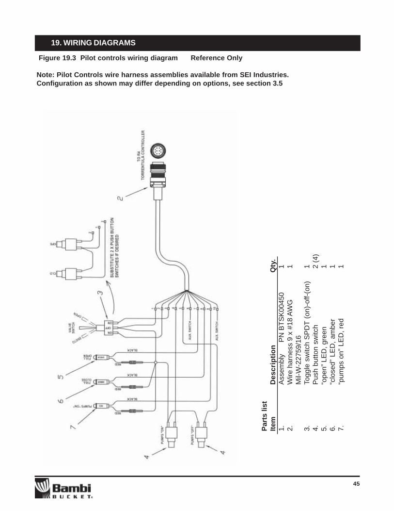
Figure 19.3 Pilot controls wiring diagram Reference Only
Note: Pilot Controls wire harness assemblies available from SEI Industries.Configuration as shown may differ depending on options, see section 3.5
Part
s lis
tIte
mD
escr
iptio
n
Qty
.1.
Ass
embl
y
PN
BTS
K00
450
12.
Wire
har
ness
9 x
#18
AW
G1
Mil-
W-2
2759
/16
3.To
ggle
sw
itch
SP
DT
(on)
-off-
(on)
14.
Pus
h bu
tton
switc
h2
(4)
5.“o
pen”
LE
D, g
reen
16.
“clo
sed”
LE
D, a
mbe
r1
7.“p
umps
on”
LE
D, r
ed1
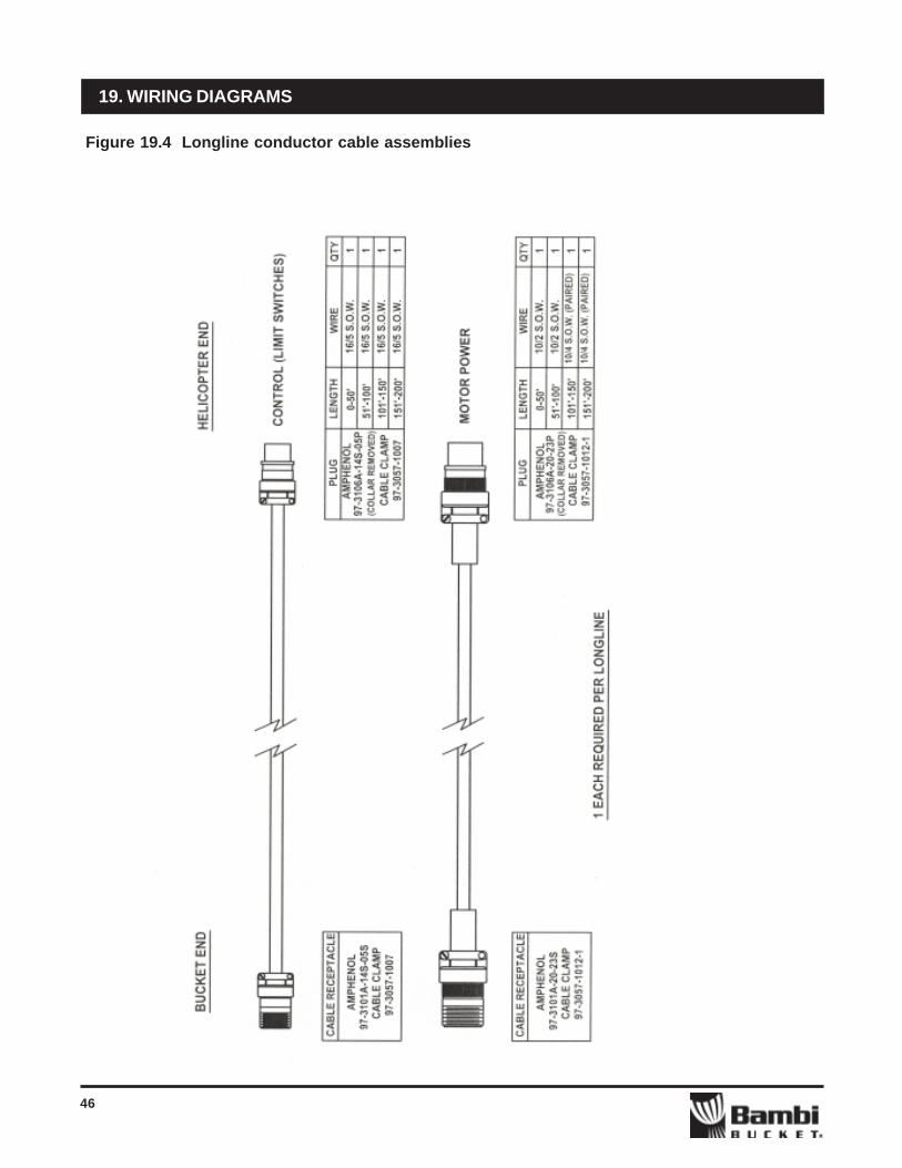
46
19. WIRING DIAGRAMS
Figure 19.4 Longline conductor cable assemblies

47
19. WIRING DIAGRAMS
Figure 19.5 Breakaway plugs conversion to Model “B” pin plugs and pin protocol

48
Figure 20.1 Controller Box Parts
20. ELECTRICAL CONTROLS PARTS ALL MODELS

49
20. ELECTRICAL CONTROLS PARTS ALL MODELS
Figure 20.2 Controller Box wire harnesses, top view lid removed

50
Table 20.1 Electrical Controls Parts List, ALL Models
20. ELECTRICAL CONTROLS PARTS ALL MODELS
1 BTSK00405 Electrical Controls Assembly2 BTSA00406 Torrentula Controller Box 13 BTSP00420 Base, Enclosure 14 BTSP00421 Lid, Enclosure 15 BTSP00423 Plate, enclosure face, with graphics 16 BTSP00424 Plate, options blank 17 BTSP00426 Tag, machine 18 BTSA00407 Control Grip assembly 19 BTSA00501 Wire Harness W1 110 BTSA00502 Wire Harness W2 111 BTSA00503 Wire Harness W3 112 BTSA00504 Wire Harness W4 113 BTSA00505 Wire Harness W5 114 BTSA00506 Wire Harness W6 115 BTSA00507 Wire Harness W7 116 BTSA00520 Wire Harness W20 217 BTSA00521 Wire Harness W21 218 BTSA00522 Wire Harness W22 119 BTSA00523 Wire Harness W23 120 BTSA00551 Wire Harness H1 121 BTSA00552 Wire Harness H2 122 BTSA00553 Wire Harness H3 123 BTSA00530 Wire Harness W30 (not shown) 124 BTSA00531 Wire Harness W31 (not shown) 125 BTSK00440 Limit Switch Kit (not shown) 1101 FBSC040305 Screw, panphil 10-24UNC x 5/8 8102 FBSC040203 Screw, panphil, 8-32UNC x 3/8 16103 FBSC030204 Screw, CSKphil, 8-32UNC x 1/2 4104 FBSC040112 Screw, panphil, 6-32UNC x 1-1/4 6105 FBSC040104 Screw, panphil, 6-32UNC x 1/2 10106 FBSF04005 Screw, panphil, 4-40UNC x 5/8 24107 FBSF04003 Screw, panphil, 4-40UNC x 3/8 4108 FNSC0203 Nylock nut, 10-24UNC 10109 FNSC0202 Nylock nut, 8-32UNC 20110 FNSC0201 Nylock nut, 6-32UNC 16111 FNSF0200 Nylock nut, 4-40UNC 28112 FNSC0204 Nylock nut, 1/4-20UNC 4113 FWS060306 Washer, plain #10 ID, 3/4 OD 4115 FWS0502 Washer, split lock #8 14201 BTSA00430 PC board Torrentula controls, model B 1202 EBRE0205 Circuit breaker, 25 amp 1203 EBRE025 Circuit breaker, 5 amp 1204 EREL011 Contactor, DPST 2205 LED indicator light, red, 24V 1206 PP013 Clamp, 3/8" ID 2207 PP014 Clamp, 5/8" ID 2208 PP265 Tie down eye strap, 2" 2209 PP722 Rubber pad 4210 FSN243 Spacer, #6 hole x 5/8" lg. 6211 PP261 Striker plate 4212 PP001 Cable Tie, nylon 2213 Receptacle cap #14 shell 1214 Receptacle cap #10 shell 1
Item # Part # Description Qty.

51
21. BAMBI BUCKET SHELL PARTS ALL MODELS
(Standard model valve shown, See Section 16, 17,18 for Torrentula Valve parts diagrams)
Figure 21.1 Bambi Bucket Shell Parts, ALL Models
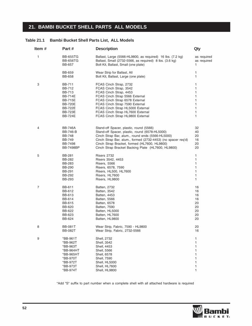
52
21. BAMBI BUCKET SHELL PARTS ALL MODELS
Table 21.1 Bambi Bucket Shell Parts List, ALL Models
Item # Part # Description Qty
1 BB-655TG Ballast, Large (5566-HL9800, as required) 16 lbs. (7.2 kg) as requiredBB-656TG Ballast, Small (2732-5566, as required) 8 lbs. (3.6 kg) as requiredBB-657 Bolt Kit, Ballast, Small (one plate) 1
BB-659 Wear Strip for Ballast, All 1BB-658 Bolt Kit, Ballast, Large (one plate) 1
3 BB-711 FCAS Cinch Strap, 2732 1BB-712 FCAS Cinch Strap, 3542 1BB-713 FCAS Cinch Strap, 4453 1BB-714E FCAS Cinch Strap 5566 External 1BB-715E FCAS Cinch Strap 6578 External 1BB-720E FCAS Cinch Strap 7590 External 1BB-722E FCAS Cinch Strap HL5000 External 1BB-723E FCAS Cinch Strap HL7600 External 1BB-724E FCAS Cinch Strap HL9800 External 1
4 BB-746A Stand-off Spacer, plastic, round (5566) 32BB-746-B Stand-off Spacer, plastic, round (6578-HL5000) 40BB-748 Cinch Strap Bar, alum., round ends (5566-HL5000) 20BB-749 Cinch Strap Bar, alum., formed (2732-4453) (no spacer req'd) 16BB-7498 Cinch Strap Bracket, formed (HL7600, HL9800) 20BB-7498BP Cinch Strap Bracket Backing Plate (HL7600, HL9800) 20
5 BB-281 Risers 2732 1BB-282 Risers 3542, 4453 1BB-283 Risers, 5566 1BB-290 Risers, 6578, 7590 1BB-291 Risers, HL500, HL7600 1BB-292 Risers, HL7600 1BB-293 Risers, HL9800 1
7 BB-611 Batten, 2732 16BB-612 Batten, 3542 16BB-613 Batten, 4453 16BB-614 Batten, 5566 16BB-615 Batten, 6578 20BB-620 Batten, 7590 20BB-622 Batten, HL5000 20BB-623 Batten, HL7600 20BB-624 Batten, HL9800 20
8 BB-081T Wear Strip, Fabric, 7590 - HL9800 20BB-082T Wear Strip, Fabric, 2732-5566 16
9 *BB-961T Shell, 2732 1*BB-962T Shell, 3542 1*BB-963T Shell, 4453 1*BB-964HT Shell, 5566 1*BB-965HT Shell, 6578 1*BB-970T Shell, 7590 1*BB-972T Shell, HL5000 1*BB-973T Shell, HL7600 1*BB-974T Shell, HL9800 1
*Add "S" suffix to part number when a complete shell with all attached hardware is required

53
22. IDS SYSTEMS ALL MODELS
IDS System Parts Diagram
Figure 22.1 IDS systems parts
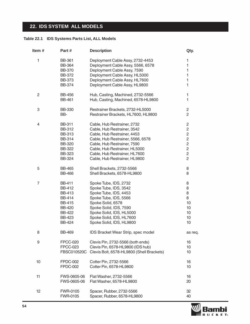
54
22. IDS SYSTEM ALL MODELS
Table 22.1 IDS Systems Parts List, ALL Models
Item # Part # Description Qty.
1 BB-361 Deployment Cable Assy, 2732-4453 1BB-364 Deployment Cable Assy, 5566, 6578 1BB-370 Deployment Cable Assy, 7590 1BB-372 Deployment Cable Assy, HL5000 1BB-373 Deployment Cable Assy, HL7600 1BB-374 Deployment Cable Assy, HL9800 1
2 BB-456 Hub, Casting, Machined, 2732-5566 1BB-461 Hub, Casting, Machined, 6578-HL9800 1
3 BB-330 Restrainer Brackets, 2732-HL5000 2BB- Restrainer Brackets, HL7600, HL9800 2
4 BB-311 Cable, Hub Restrainer, 2732 2BB-312 Cable, Hub Restrainer, 3542 2BB-313 Cable, Hub Restrainer, 4453 2BB-314 Cable, Hub Restrainer, 5566, 6578 2BB-320 Cable, Hub Restrainer, 7590 2BB-322 Cable, Hub Restrainer, HL5000 2BB-323 Cable, Hub Restrainer, HL7600 2BB-324 Cable, Hub Restrainer, HL9800 2
5 BB-465 Shell Brackets, 2732-5566 8BB-466 Shell Brackets, 6578-HL9800 8
7 BB-411 Spoke Tube, IDS, 2732 8BB-412 Spoke Tube, IDS, 3542 8BB-413 Spoke Tube, IDS, 4453 8BB-414 Spoke Tube, IDS, 5566 8BB-415 Spoke Solid, 6578 10BB-420 Spoke Solid, IDS, 7590 10BB-422 Spoke Solid, IDS, HL5000 10BB-423 Spoke Solid, IDS, HL7600 10BB-424 Spoke Solid, IDS, HL9800 10
8 BB-469 IDS Bracket Wear Strip, spec model as req.
9 FPCC-020 Clevis Pin, 2732-5566 (both ends) 16FPCC-023 Clevis Pin, 6578-HL9800 (IDS hub) 10FBSC010520C Clevis Bolt, 6578-HL9800 (Shell Brackets) 10
10 FPDC-002 Cotter Pin, 2732-5566 16FPDC-002 Cotter Pin, 6578-HL9800 10
11 FWS-0605-06 Flat Washer, 2732-5566 16FWS-0605-06 Flat Washer, 6578-HL9800 20
12 FWR-0105 Spacer, Rubber, 2732-5566 32FWR-0105 Spacer, Rubber, 6578-HL9800 40
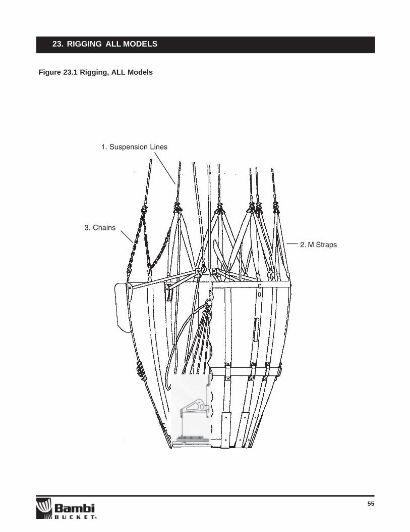
55
23. RIGGING ALL MODELS
1. Suspension Lines
3. Chains
2. M Straps
Figure 23.1 Rigging, ALL Models

56
23. RIGGING ALL MODELS
Item # Part # Description Qty.
1 BB-836 Suspension Line Set, 2732-4453 4 pairs/setBB-837 Suspension Line Set, 5566 4 pairs/set
BB-838 Suspension Line Set, 6578-HL5000 4 pairs + 2 singles/setBB-842 Suspension Line Set, HL7600 4 pairs + 2 singles/setBB-844 Suspension Line Set, HL9800 4 pairs + 2 singles/set
2 BB-677 M-Strap, 2732-4453, Loop 8BB-678 M-Strap, 2732-4453, Straight 8BB-679 M-Strap, 5566, Loop 8BB-680 M-Strap, 5566, Straight 8BB-681 M-Strap, 6578, 7590, Loop 10BB-682 M-Strap, 6578, 7590, Straight 10BB-683 M-Strap, HL 5000, Loop 10BB-684 M-Strap, HL 5000, Straight 10BB-685 M-Strap, HL 7600, Loop 10BB-686 M-Strap, HL 7600, Straight 10BB-687 M-Strap, HL 9800, Loop 10BB-688 M-Strap, HL 9800, Straight 10
3 BB-782 Chain Top, 18-1/2”, 2732-5566 2BB-783 Chain Top, 20-1/2”, 2732-5566 2BB-783S Chain Top, Set 2732-5566(2XBB-782, 6XBB783) 1BB-784 Chain Top, 19 ½”, 6578-7590 2BB-785 Chain Top, 20 ¾, 6578-7590 2BB-786 Chain Top, 17 ½, HL 5000 2BB-787 Chain Top, 21 ½, HL 5000 2BB-788 Chain Top, 26", HL 7600 2BB-789 Chain Top, 28", HL 7600 2BB-789S Chain Top, Set, HL7600(2XBB-788, 3XBB-789) 1BB-790 Chain Top, 32", HL 9800 2BB-791 Chain Top, 34", HL 9800 2
Table 23.2 Rigging Parts List, ALL Models
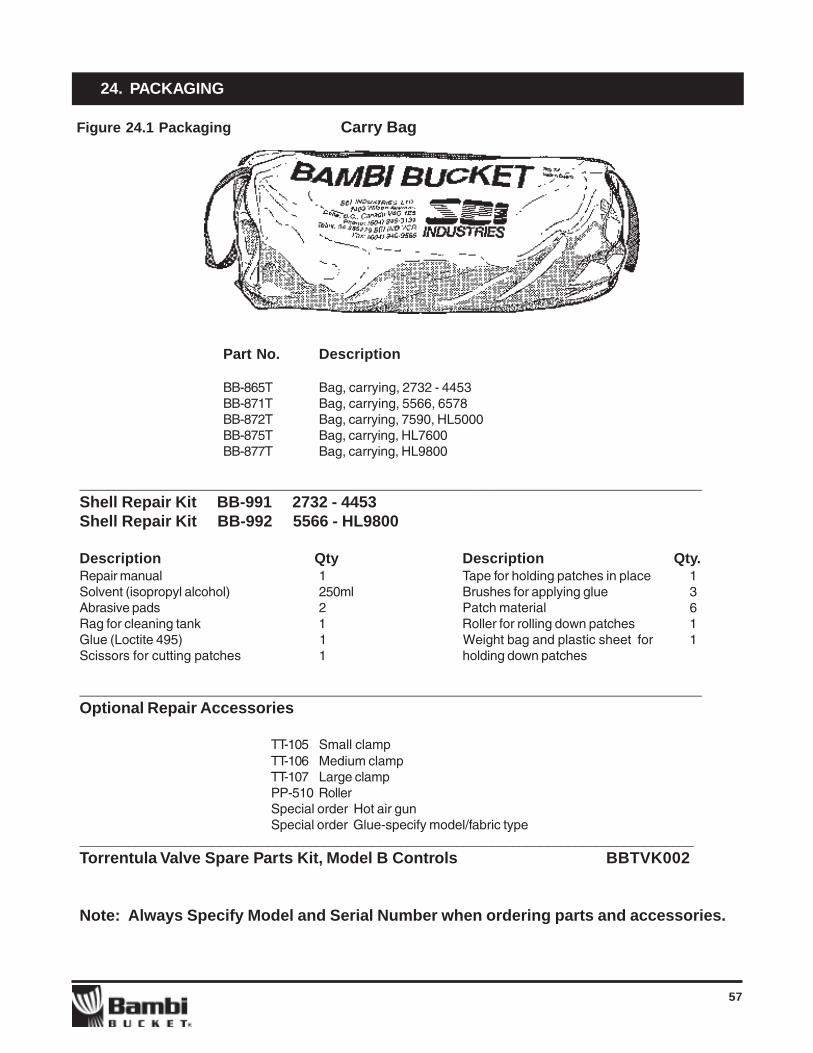
57
24. PACKAGING
Part No. Description
BB-865T Bag, carrying, 2732 - 4453BB-871T Bag, carrying, 5566, 6578BB-872T Bag, carrying, 7590, HL5000BB-875T Bag, carrying, HL7600BB-877T Bag, carrying, HL9800
______________________________________________________________________________Shell Repair Kit BB-991 2732 - 4453Shell Repair Kit BB-992 5566 - HL9800
Description Qty Description Qty.Repair manual 1 Tape for holding patches in place 1Solvent (isopropyl alcohol) 250ml Brushes for applying glue 3Abrasive pads 2 Patch material 6Rag for cleaning tank 1 Roller for rolling down patches 1Glue (Loctite 495) 1 Weight bag and plastic sheet for 1Scissors for cutting patches 1 holding down patches
______________________________________________________________________________Optional Repair Accessories
TT-105 Small clampTT-106 Medium clampTT-107 Large clampPP-510 RollerSpecial order Hot air gunSpecial order Glue-specify model/fabric type
________________________________________________________________________________________Torrentula Valve Spare Parts Kit, Model B Controls BBTVK002
Note: Always Specify Model and Serial Number when ordering parts and accessories.
Figure 24.1 Packaging Carry Bag


![BB Instructor Manual for Release 8[1]](https://static.fdocuments.in/doc/165x107/577dab811a28ab223f8c8417/bb-instructor-manual-for-release-81.jpg)