BASS BASIN, TASMANIA DRILLING PROGRAM WHITE...
117
534COt T/18P BASS BASIN, TASMANIA DRILLING PROGRAM WHITE IBIS·1 APRIL 1998 REV 0 01<- 04-378
Transcript of BASS BASIN, TASMANIA DRILLING PROGRAM WHITE...

534COt
T/18P
BASS BASIN,TASMANIA
DRILLING PROGRAMWHITE IBIS·1
APRIL 1998REV 0
01<- 04-378

White Ibis-I Dry Hole DriIIing Program
PREMIER OIL AUSTRALASIADRILLING PROGRAM
EXPLORATION WELL WHITE IBIS-I
DISTRIBUTION
53 L1002
Carol Bacon x 2A NadjiRichard GrayDermot O'KeeffeJohn Begg, General ManagerMark Pogson, Bass Basin Team LeaderBlaine M Uhner, Operations ManagerGordon Hnnter, Project Drilling Eng.Drilling SnpervisorDavid Evans, Operations GeologistWellsite GeologistRick White, Logistics SnpervisorAngns GuthrieRig ManagerRig ToolpusherSpare copies at rig x 2IS Coordinator
Ref Ops/BasslWhile Ibis/Drilling Program
Minerals & Resources TasmaniaDME, VictoriaPremier SingaporePremier LondonPremier Oil AustralasiaPremier Oil AustralasiaPremier Oil AustralasiaPremier Oil AustralasiaPremier Oil AustralasiaPremier Oil AustralasiaPremier Oil AustralasiaPremier Oil AustralasiaBoral Energy Resources LtdNorthern Explorer illNorthern Explorer IIINorthern Explorer IIISchlumberger
April 1998Rev 0
White Ibis·I Dry Hoi. Drilling Program
WHITE IBIS-l
DRY-HOLE DRILLING PROGRAM
534C03
REVISION ISSUE
DATE ISSUED
PREPARED BY
APPROVED BY
APPROVED BY
AUTHORISED BY
Ref Ops/BasslWhit. Ibis/Drilling Program
if
o
APRIL 1998
April /998Rev 0

While Ibis-l Dry Hole Drilling Program
CONTENTS
1. OPERATIONS ORGANOGRAM
2. SECURlTY OF INFORMATION POLICY
3. WELL SUMMARY
4. LOCATION MAPS
5. WELL OBJECTIVES
5.1 Safety and Environmental
5.2 Geological & Reservoir Objectives
5.3 Drilling Engineering Objectives
6. GEOLOGICAL INFORMATION
6.1 Predicted Section
6.2 Formation Description
6.3 Shallow Gas
6.4 Pore Pressure Gradients
6.5 Fracture Gradients
6.6 Temperature Gradients
6.7 Anticipated Hydrocarbons / C02 / H2S
7. DRILLING TIME DEPTH CURVE
8. WELL PLAN OUTLINE
9. RIG MOVE & ANCHOR PLAN
9.1 Environmental Conditions in the Bass Straits
9.2 Anchor Location
9.3 Anchor Plan
9.4 Rig Positioning
10. DRILL 914MM (36") HOLE - RUN 762MM (30") CASING
11. DRILL 444MM (17Y2") HOLE - RUN 340MM (13'/.") CASING
12. DRILL 311MM (12'1.") HOLE - RUN 244MM (9'/.") CASING
Ref Ops/BassIWhite Ibis/Drilling Program
1
2
3
4
66
66
7
78
9
9
9
910
11
12
1313
13
1314
16
22
27
April 1998Rev 0

White Ibis-] Dry Hole Drilling Program
APPENDICES
Appendix A Geology Summary & Formation Evaluation
AppendixB Drilling Fluid Program
AppendixC Cementing Program
AppendixD Casing Design Parameters
AppendixE Blowout Preventer Pressure Testing
AppendixF Wel1head Stack-Up Diagram
AppendixG Reference Documents
AppendixH Support Services
AppendixJ Contact Listing
Ref OpslBassfWhite Ibis/Drilling Program
534C03
April i998Rev 0

White Ibis-I Dry Hole Drilling Program
1. OPERATIONS ORGANOGRAM
53,H~OG
Pagel
PremierOilAustralasia
SINGAPORE
BASS BASIN ORGANOGRAM
OPERATIONSMANAGER
SINGAPORERG
PERTH GENERALMANAGER
JB
IFINANCE
TEAMLEADER .... ---"~'" ---._.. ----.. -----,
MH · .MP
: IOPERATIONS MANAGER · . .___ .L ___ • ______ •••• ___ •••• L
o
___ '
BMU · .· .· .· .· .· .· .· .· .Operations Petroleum OperationsAccountant Engineer Geologist
MC TBA DE
SHOREBASE PROJECT DRILLINGENGINEER
loS. LogisticsCo-ordinator RW
RIG SITE
DRILLINGSUPERVISOR
lineWellslteDrlliing Engineer Geologistfunction
Operations Manager: Blaine Ulmer (BMU)
Project Drilling Engineer:
Team Leader:
(Bass Basin)
(Bass Basin)
Gordon Hunter
Mark Akers (MA)IMark Pogson (MP)
MHJBBMUSH
Mark HancockJohn BeggBlaine UhnerStuart Harrison
DE Dave Evans
Ref Ops/BassiWhite Ibis/Drilling Program April 1998Rev 0

White Ibis-I Dry Hole Drilling Program
2. SECURITY OF INFORMATION POLICY
~ ""1 " '\~j .0 L . ~,) 'J
Pagel
Normal security measures will be taken to ensure that all information gained from drilling
White Ibis-! will be kept confidential, To accomplish this, the following procedures will beobserved.
1. Information should not be transferred to any person other than Premier personnel
and service staff directly involved in the planning, drilling and testing of this well,
2. No unauthorised personnel to be allowed on the rig.
3. Only the drilling crews, Service Company personnel and Premier personnel are
allowed on the rig site. No visitors will be allowed unless authorised by the PremierProject Drilling Engineer in Geelong.
4. Daily drilling information will be distributed to partners by the office in Perth. If
requests are made for information, this request should be referred to the Premier
Team Leader in Perth.
5. The logging operations will be supervised by Premier Oil personnel,
6. The logging information will be kept confidential, Only information which will help
the Drilling Supervisor, Toolpusher and Wellsite Geologist perform more efficiently
and maintain well control will be kept onboard the rig.
7. Only personnel authorised by the Drilling Supervisor and Well Site Geologist will
have access to the logging unit during logging operations.
8. No public announcements will be made except as written and authorised by the Perth
office of Premier OiL
9. All service personnel, particularly Mud Loggers, Wireline Logging Engineers and
Cementing Engineers, should have the above emphasised at the time of their arrival
at the rig, and also at the time of their departure.
10. The Joint Venture partner after proper notification to Premier, will have full & open
access for their representative(s) to monitor the drilling operations including wireline
logging, coring and testing.
Ref Ops/Bass/White Ibis/Drilling Program April/998Rev 0
While Ibis-I Dry Hole Drilling Program
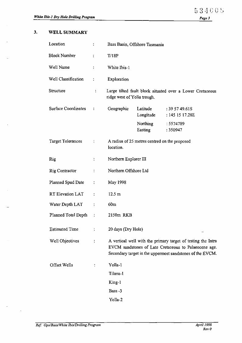
3. WELL SUMMARY
Location
Block Number
Well Name
Well Classification
Structure
~ 3- /1 i\ n (,.} . "1 '.I V~,
Page3
Bass Basin, Offshore Tasmania
TIl8P
White Ibis-l
Exploration
Large tilted fault block situated over a Lower Cretaceousridge west of Yolla trough.
Surface Coordinates Geographic Latitude
Longitude
Northing
Easting
: 39 57 49.61S
: 145 IS 17.28E
: 5574789
: 350947
Target Tolerances
Rig
Rig Contractor
Planned Spud Date
RT Elevation LAT
Water Depth LAT
Planned Total Depth
Estimated Time
Well Objectives
Offset Wells
ReI Ops/BasslWhite Ibis/Drilling Program
A radius of 25 metres centred on the proposed
location.
Northern Explorer ill
Northem Offshore Ltd
May 1998
12.5m
60m
2150m RKB
20 days (Dry Hole)
A vertical well with the primary target of testing the Intra
EVCM sandstones of Late Cretaceous to Palaeocene age.
Secondary target in the uppermost sandstones of the EVCM.
Yolla-I
THana-l
King-I
Bass -3
Yolla-2
April 1998Rev 0

White Ibis-l Dry Hole Drilling Program
4. LOCATION MAPS
Ref Ops/BasslWhite [bisIVrilling Program
534CODPage 4
April 1998RevO

•
144o E:NDIGO
o S:YMOUR
.. ,-~
534C10
1 •-:
,,• o EALLARAT VICTORiA
I'!
..,'-
PrcmierOilAcstrgi2.Sla
THE eASS PROJECT
WELL AND ;;::iMIT LCCATiCNS
c
Scm
I.. @ MELBOURNE,....-...... ~..,/' '''"\
I, G::LONG~: )
I'; SLACKROCK~ :' ;-:;'=", /, , ,.~ e, "A ./
I -,,-' " ~ --:=-' /,,- -' ~,,I I' e-..,a...:~- ~, ,.. -, d
" --'" ',..r?,' ~...'I ~ .~ ~~;::;,;.-" _':"t.... ..~:.:,,-'I ;...: ,,\,-.,...; ;:I ;-., ~ I:,----- - -- -- --- ---------- - _...::- -- --~ -- - --- ----_ ... -- - -j!:
!! -, ll-j.... L. ~ 11! 'I' .~ t T/18?r JIJr. I EI:\lE?SISL.-\\~..;-"'~' Ii!\ _:; L ' I _ ......., -- ·~o i,1
, I "'t""- Rl"":'G IS!..A.....O 'L I~ J <'-:..,,,:;;. !,! !III U'I -. ~----~:. q..= " ._.,........... 1'1
'.,J I. i ...-:."~ .:.,.... :,...,------ ~
II I ',.J !' ~./ ~ I:~, ~-.,.:::..':::. T!2S? " ,_ .. __ .. r-- .;f' :1 ;
..
'1,1 1 .....~~-~._~ .! ~ / -.~~ I i~ - • .. j- --.- ":, '
9",: t"'G~T Lt..1TA '-ot.-. ..:w' / "':j !
~ q _, t-I'~J"- ..~~ ~./ ,;,;\:1 j
I" " :_~,,'.I= - . J--' ... E=' I ='v 1'1
I \.I \,11 )'" ~"ho-':j ..-..;.-=.~ --- _f"'\. Ij
.. II, '\ .:..~, 11
~ !II <:\ TASrvL~NIA S ii~.,
"l!f
"FIGURE 1

534Cl1z
145 15 E 145 30 E 14545 E~'"~
en +:;l +co'"
Z
+ + + ~"*"CORM RANT 1 N
'""*"KING '"
PremierOilAustralasia
...,
o!
5 10 15! !
KILOMETRES
Scm
20 THE BASS PROJECT
WELL AND PERMIT LOCATIONS
-,-

White Ibis-I Dry Hole Drilling Program
5. WELL OBJECTIVES
5.1 Safety and Environmental
• Incur no lost time accidents for the duration of the welL
• Successfully utilise water based mud throughout the welL
• Implement H2S procedures if required,
5.2 Geological & Reservoir Objectives
-"'1"~ ;)' 'j
Page 6
The detailed geological summary and fonnation evaluation programme is enclosedin Appendix A.
The geological objective is planned to be drilled in the 3llmm (12Y.") hole section,Planned ID for the well is 2150 m RKB,
The primary objective is to appraise the hydrocarbon bearing potential of the EasternView Coal Measures,
• Run a full suite of electric logs and, dependent upon shows, run the following
optional logs: MDT, FMS and CMR or equivalent.
5.3 Drilling Engineering Objectives
• Successfully drill well with modified casing program, avoiding need for drilling
hole to ID in 216mm (8 W') hole,
• Drill all hole sections with WBM and avoid any stuck pipe occurrences,
• Minimise fonnation damage particularly in the reservoir section,
• Implement Anchoring Analysis to minimise anchor handling time,
• Drill well under AFE and within 20 days
Ref Ops/Bass/White Ibis/Drilling Program Apri/1998Rev 0

White Ibis-I Dry Hole Drilling Program
6. GEOLOGICAL INFORMATION
6.1 Predicted Section
Ref Ops/BasslWhite Ibis/Drilling Program
534C1:":Page 7
April 1998Rev 0

53 L r. ,1~
PremierOilAustralasia
T/Rl1 • BASS BASIN
PREDICTED SECTION
WHITE IBIS - 1
SP 1139 on line BHB96-10739°57'49.61"S145°15'17.2S"E 5 em12.5 metres 1100.._---=:::.-----11»00-11
PTD 2150mSS
seismic Line °
Latitude °
Longitude °
K.B. Elevation °
LOCATION:
STRATIGRAPHY LITHOLOGY REMARKS DEPTHmetres melres lWT
Seismic Marker * below t<-B. subsea (msoc)
"56. Floor' I- 73 - - 60
'FIec8nt,Mid Miocene'
Iz "-::::>w00w a: I- 713 - - 700a:: " -L -L
0 >-... -L -L> W «z ::::> -L -L ..L-
a: w 000 a: -L -L -
c:( :E 0IJ- - -....
..L-_ -:-_ "Mid Miocene"- -
I-f;...;:'- -L -
r.::;:::' ..L- ..L-
a: - -..L- -L -
, 1-1163- f- 1150W - --
,...L .I- -- -- ~ ~
, L
- ..L -'r ,
*.~
I- 1441 - f- 1428 - I- 1297--- - .:z:: "Demons Bluff- - - Formation"_.- - -
>----- *- .=:c..;.... I- 'TopEVCM o I- 1595- f- 1582 - I- 1393-w .
z*
. ,.
I- 1647- f- 1634 - I- 1424-w "- 'Top Lower
8 ::::> - - - N.asperus"0w a:
" - - --
~_. -- .'
w -Middle~
- 1---=--=-- I- 1564-> * I- M.diversus" I- 1904- f- 1891 -z *' . ,
'Top I- 1937- I- 1924 - I- 1601 -w z Palaeocene"0 a: * "Jntra I- 1988- I- 1975 - 1-1630 -fa w Palaeocene":5 ....
*--- --I- "Late I- 2058- f- 2045 - I- 1668--_._- ---_._----.. U> ...... . Crataceous"
Q. « *. - "New Top 1-2113- f- 2100 - I- 1695-0 w -' .. Bassmant·
2163 2150TOw;I<!li Apri,l998mil,;,;;';:_~.;:;:'u"""'=""""',"""J-----------------------------------J

White Ibis-] Dry Hole Drilling Program
6.2 Formation Description
Torguay Group: Seabed - 1440m RKB
Recent to Middle Miocene
Page 8
Upper carbonate section and a lower claystone section with the change occurring at
around 700m. The claystone is calcareous and is soft to firm and can be highly
dispersive in parts.
Angahook Formation
This formation is not expected to be intersected in White Ibis-I
Demons Bluff Formation; 1440 - 1594m RKB
Late Eocene
Claystone with thin interbeds of sandstone and dolomitic limestone.
Eastern View Coal Measures: 1594 - 2112m RKB
Late Eocene to Early Palaeocene
The contact between the EVCM and the overlying Demons Bluff Formation is
gradational with shales becoming more silty and sandy.
Using Bass-3 offset data the first major sand package in the EVCM is a very fine to
fine grained with minor medium to very coarse grained intervals, are glauconitic
with an argillaceous matrix and show very minor cementation by mictite or dolomite
elements.
The next thick section of interbedded sandstones, siltstones and shales at Bass-3
coincided with the intersection of the first clean consolidated sandstone and a series
of interbedded coals from 1767m to 1898m. The sandstone, possibly a channel sand,
has coarse to granule sized, milky to clear, sub rounded to rounded quartz grains
with minor associated pyrite. However the dominant sandstones within this interval
are micaceous and very fine to fine grained with a white (kaolinite?) matrix These
sandstones are typically interbedded with brown to black carbonaceous shales. The
coals tend to be black in colour with a brilliant lustre, brittle and exhibiting a
conchoidal fracture.
From 1900m until the next major sandy interval at 2054m the section at Bass-3
comprises a series of coal-dominated terrestrial deposits with lesser amounts of shale
and minor sands interfingering with interbedded pyritic clacareous claystones,
fossiliferous shale, and glauconitic, very fine grained sandstone with a clay matrix.
Between 2054mand 2158m a series of well sorted medium to coarse grained
Ref' Ops/BassIWhite IbislDrilling Program April 1998Rev 0

White Ibis-] Dry Hole Drilling Program Page 9
sandstones and friable quartz sands interbedded with brown to grey micaceous andsilty shales were intersected. The sandstones at 2054m from which hydrocarbonswere recovered via a FIT, exhibited a slight odour but did not fluoresce.
Between 2158m and the base of the EVCM at 2375m in Bass-3, the sedimentarypackage comprises an interbedded sequence of sandstone, siltstone and shale.Individual bed thickness is variable with no particular rock-type showing overalldominance. The sandstones are typically light grey, matrix supported and show arange in grain size from fine grained to granule sized. Weathered feldspar content ishigher compared with sands higher up in the EVCM. The grains are typically subangular to rounded and poorly sorted. Matrix may also include minor amounts ofmica and carbonaceous shale. The siltstones are generally light brown to light grey,argillaceous in part, micaceous and pyritic. The shale is light to mid grey,occasionally silty and micaceous. Coal may be present, but usually only in traceamounts
Basement: 2112 2150m RKB (TD)
A metamorphic interbedded sequence of quartzite, recrystallised siltstone, finegrained sandstone and black meta shales. White Ibis-l is expected to penetrate up to50m ofbasement.
6.3 Shallow Gas
Shallow gas has not been encountered in any of the offset wells and is not expectedon White Ibis-I.
6.4 Pore Pressure Gradients
Offset data indicates that all the formations are expected to be normally pressured,with a seawater gradient 1.042 s.g. EMW. RFT data from Yolla-I gives formationpressures of 1.040 s.g. at 2820m. Background gas is not expected until 950m.
6.5 Fracture Gradients
In the primary offset wells Leak-Off tests were not performed, however FormationIntegrity Tests have been performed in both the Torquay Group and the DemonsBluff Formation. These have given up to 1.83 s.g. EMW at 416m and 1.75 s.g.EMW at 1660m respectively (Tilana-I, Yolla-I gave 1.5 s.g EMW at 400m. and1.63 s.g. EMW at 1752m for the same formations). No leak off has been recorded inany of the offset wells.
6.6 Temperature Gradients
The geothermal gradient for White Ibis-I is expected to be 3.16 deg CllOOm. with aBHT of 85 deg C (assumes a mud line temp of 14 deg C). Gradient based on offsetlogging .data.
Ref Ops/BasslWhite IbislDrilling Program April 1998Rev 0

White Ibis-I Dry Hole Drilling Program
6.7 Anticipated Hydrocarbons / C02 / H2S
53LJG1:' PagelO
Bass-3 the nearest offset well produced hydrocarbon from sandstones at 2054m
RKB
CO, In the control wells C02 contamination of the drilling fluid has been aproblem, and C02 can be expected in the White Ibis-l well. Offsets suggest that the
C02 can be expected below l700m, however using a KCl/polymer/PHPA mudsystem for the 31lmm (l2Y.") section should avoid any related problems.
H,S H2S has not been recorded in any of the control wells and is not expected in
the White Ibis-l well.
Ref" OpslBasslWhite Ibis/Drilling Program April 1998Rev 0

While lbis-l Dry Hole Drilling Program
7. DRILLING TIME DEPTH CURVE
Ref OpslBasslWhite Ibis/Drilling Program
534GPagell
April 1998Rev 0

53 LIC1!)
Premier Oil AustralasiaWhite Ibis-l
Preliminary time-depth prognosis, excluding contingency
1
~• Position rig I ru anchors ( 2 day). • Drill 914mm (3 ") hole ( 0,25 da s)- Run PGB & 76 mm(30") Cso ( ( .75 days)
\ - Drill 444mm (1 1/2") hole ( 2 d, ys)- Run 340mm C g & N/U BOPs (' days)
4 f • Drill 311 mm (1 2 1/4") hole (9.5 ( ays)- Log, run 244 (I 5/8") mm Csg ( .5 days)
1\" \
\\
1\ 6
\0
\0
\ ..•
1\\ ,
0
0
o
250
500
750
2,50
2,25
2,000
1,75
~ 1,000
=,sg< 1,250
'"0
1::E 1 50
a 5 10 15Days from spud
20 25
Scm

White Ibis-l Dry Hole Drilling Program
8. WELL PLAN OUTLINE
Ref OpslBass/White Ibis/Drilling Program
53LIC20Page 11
April /998Rev 0

White lbis-l : WELL PLAN OUTLINE534021
BLOCKSURFACE LOCATIONTDPROVISIONAL SPUD DATE
Till', .... Stnlu39dq; sr 49.61"5' 145dq U' 11.2'''£21,,- ...d RKB15oM.y-"
WELL CLASSmCATIONRICWATER DEPTHRTE (ab.", N' inrI)
EJp"'gt""Drill'blp • Npdhm I:,plprtr PIu.s........ '_'I T... ... ,........ Potrall.. H'" c...."e'lIIl. w.. ....... ... '-- J:nludoa DrlIU•• .... --- c_nO '-- '........ 'rannProI\Ic,- I~_-
161_lit., 'hi bdow ML ka...,",.~""T....., 1·1·1 wiNO N_ " 161_ l'lI~) 4ft "- CR • ST-1 ...eo- Sl""7 •.".hi W............... ... Sa_tr. III oil......
~"""'I""'I.'"T• ...,.,. •.,. te 150-
J.1·1 N_ ...- ~~~:'::~=-~\(
11 Jl4~....., lo.OOOpIl"'11la 10'....,
MltdWTI.I.I.l,.
'OC"(I r..) '%KOfPoIy_
f-!!!!- PH'A."~,.
,
f--
.~I--- .,',
. Talililany 1'"101400M, Sdf 1luI1•• 1oIHI..- for ""'b1r PST 1.I:VCM
"" ••N~
,..._- PI"'" hprmN~
'.: ie-.. ..s,..c....-.. T.,&VCM _.-
So., N~n,
I CM_
- ,- ~
ntS-~s.k
MDTCOIC...·--.-
VS,
- If
1.,....,
.' , <Sf
"",U:
HOT "'" W_..TO
SCAU
I .)11- ~"".,7t..ap uo. New VA.\(J VAM ACE • $pecbI Drift
e-""
,IWEUmATJ/jQIl~ u I.: ... u u
ro""'. DDtaCTlO!'IAL stlJtnys 1Mw,'".Mw,'"
914mJl1 : Allderdrirt444.... : Aadtrdrin .ntb EMS.I JtctlOIl TO311mllll : Aadtrdrtn tritlli EMS at TO
",n".I. All depths and formation lOps an m tvd RKB PCRM w"" nucL The: primary obje:c:llvn of Ihe well arc Intra EVeM sandslones of Palaeoce:ne to Early Eoccne ace ........ WT ....J. The: K<ondary obje:c:t1ves of the: we:1I arc the: upper most sands of the: Eastcrn View Coal Measures
'"-'... ......-- ....... ltta1W..,",U'"
Scm
-----

White Ibis-] Dry Hole Drilling Program
9. RIG MOVE & ANCHOR PLAN
9.1 Environmental Conditions in the Bass Straits
53 L1G22Page 13
Wind roses for the months April through July for the Bass Straits indicate apredominant westerly wind with a tendency towards the northwest and becomingpredominantly northwest in July. These winds account for some 40% of the time.Wave roses for the same period show a predominant southwesterly direction with atrend towards west and northwest. This southwesterly tendency accounts for some25% to 30% for April to June and then tends towards west and northwest in July.
Currents in the Bass Straits are understood to be relatively weak in the area aroundthe White Ibis-I location. Although tidal currents of around I m/s occur at bothentrances (east and west) to the Bass Strait, they occur to all intents simultaneouslyand cancel one another out in the area concerned. Wind driven currents are said to beof the order of 2% of wind speed, and are therefore very weak.
On the basis of this information it would appear that a heading of 265deg wouldappear best in order to satisfy all the above elements. It is understood from themaster of the Northern Explorer III that the heading can be adjusted by up to 20degby manipulation of the mooring lines. This would allow for the vessel to stem anyviolent winds from 245deg round 285deg.
In July the wind as stated tends to be mainly from the northwest at around 15m/sec,but the waves remain predominantly from west by south with significant heights ofaround 3m. This would put the wind some 50deg on the starboard bow and the swell45deg on the port bow. Adjustment of heading would then have to be towards themore violent of the elements, and some downtime whilst waiting on weather isbound to occur.
9.2 Anchor Location
White Ibis-I location : 39deg 57' 49.61"8 145deg 15'17.28"E
Water Depth:
9.3 Anchor Plan
60m
It is understood that the anchors for the Northern Explorer III are numberedsequentially clockwise from the after port bow anchor, i.e. #Iand #2 anchors are onthe port bow. '
The master has expresses a desire to opt for a 35deg anchor separation at the bowand similar at the stern.
This will allow for flexibility in the heading adjustment and at the same timeposition the bow anchors in the direction of the prevailing wind and waves.
Ref' Ops/BasslWhite Ibis/Drilling Progrom April 1998Rev 0

White Ibis-l Dry Hole Drilling Program Page 14
Anchors would therefore, if the recommended heading of 265deg is used, be placedas fonows :-
#1
#5195
015#2
#6230050
#3#7
300120
#4#8
335155
Each anchor leg will consist of the fonowing :-
Maximum outreach of2.75" rig anchor wire to750ft of 3" ORQ Stud link chain400ft of2.75" wire pennant
25 links 00" ORQ chainI x 9 MT Stevpris anchor
400ft of2.75" wire pennantsurface marker buoy
The chain win be in 250ft lengths and this win require 2 Kenter Joining Links peranchor leg i.e. 16 kenters. A further 8 kenters should be available as spares. (Thepractice of hammering cold lead plugs into the locking pin aperture should be
discouraged as it has been found on occasions that these can fail molten lead shouldbe poured into the locking pin aperture)
Other shackles in the system should be consistent with the breaking load of the wire.
The test certificates for an the above should be available, and the ART should note
and record the identifying number and exact positions of an the shackles in use inthe system. This is particularly important in the case of any accident or incident that
may result in an injury.
9.4 Rig Positioning
Prior to commencing run-in to new location, if time and weather permit;- a gyrocalibration/check should be performed.
Distance and bearing to intended location and first anchor drop are to be displayedcontinuously, together with speed, heading, CMG, position quality, off track
distance and position of rig in geographical and grid co-ordinates. As the first anchordrop position of the relevant anchor fairlead in relation to the run-in line to be clearly
seen. The system win, if selected, track the appropriate fairlead as opposed to the
rig's datum. A fix is to be taken when the anchor is dropped and the GNS anchorlocation file updated accordingly.
As the rig continues towards location, comparison is to be made between distance
travened from the anchor drop point and the amount of chain veered to detect any
anchor drag or excess of chain.
ReI Ops/BassIWhite Ibis/Drilling Program April 1998Rev 0

White Ibis-l Dry Hole Drilling Program Pagel5
As the rig continues towards location, comparison is to be made between distance
travelled from the anchor drop point and the amount of chain veered to detect anyanchor drag or excess of chain.
During pre-tensioninglballasting operations, the rig's position is to be monitored
When the rig has been accepted by the Premier Survey representative and Drilling
Representatives as being within the required positioning tolerance for the location a
Final Fix Analysis is to be performed within GNS.
As a minimum, I hour of observations, at a 10 second interval (approx. 360 samples)
is to be obtained for all positioning systems. For DGPS the observation period
should include at least three constellations with PDOP less than 4 and with five or
more SV's.
Before collecting DGPS data for the final fix, the satellite availability for AII-In
View PDOP vs Time should be consulted and/or made using Mission Planning
software with a recent almanac (Note: Almanacs should be valid for 3 months from
date of down load). The prediction should be made with an elevation mask of 15 0
and the appropriate curtains for the drilling rig's derrick. From the All-In-View
PDOP vs Time prediction, a suitable period for collecting the final fix DGPS data is
to be selected and advised. The minimum elevation mask to be set during the
collection of the final fix DGPS data is 100 and if MultiFix 2 is in use a delta of 50
is to be set.
On completion of final fix analysis, the Premier Survey Rep and Drilling
Representatives shall be advised of the rig's drill stem location in relation to the
intended location and position tolerance. Graphic screen dumps should be used to
ensure that all relevant personnel are fully aware of the drill stem's location.
Ref Ops/Bass/White Ibis/Drilling Program Apri/1998Rev 0

White Ibis-I Dry Hole Drilling Program
10. DRILL 914MM (36") HOLE - RUN 762MM (30") CASING
53L}C~J
Page 16
This program and the procedures outlined herein are intended as a guide. The DrillingSupervisor will hold a regular morning meeting with contractor personnel to review plannedoperations during the next 24 hours. This project is a team effort and all personnel areexpected to participate on this basis. Ideas on how to improve procedures which will result ina more efficient and safer operation will be encouraged at all times by the DrillingSupervisor.
Objective
Drill sufficient 914mm (36") hole to provide 2.4m (8') from top of the 762mm (30")WH to the mud line.
Use lightest weight on bit reasonable to safeguard against developing hole angle.
914mm (36") Hole Preparation
• Mix sufficient pre·hydrated gel mud for section and Guar Gum Hi-Vis sweeps.
• Make up 914mm (36") drilling assembly.
• Install the bullseye on the PGB.
• Paint the bottom of the 762mm (30") shoe joint white and paint 1m spacing lines on the
bottom Sm of the shoe joint.
• Paint 1m spacing lines on the top Sm of the 762mm (30") below the housing joint.
• Paint the bottom of the 340mm (133/,"), shoe joint white and paint 1m spacing lines on
the bottom Sm of the shoe joint.
• Pressure test the BOP's/choke manifold/standpipe.
• Ensure 762mm (30") elevators fit around 762mm (30'') conductor.
• MIU 762mm (30") running tool and rack back in derrick.
• Dispatch water samples to Cement Contractor for lab testing.
Bit Program for 914mm (36") Hole Section
lADe In/Out m WOB RPM AvROP Hourskg m/hr
1-1-1660mrn Seabed 62 Sk - 10k 80 40 1.5(26") + /132
914mrn (36")hole opener
Ref Ops/Bass!White Ibis/Drilling Program April 1998Rev 0

White Ibis·] Dry Hole Drilling Program Page 17
A detailed hydraulics plan will be issued prior to spud, however general guidelines are:
Nozzles:
Pump Pressure:
Flow Rate:
Bit - 3 x 22, I x 20 : Hole opener - 4 x 16
12500 kPa
4500lpm
Drilling Fluid Program
Refer to Drilling Fluids Program in Appendix B for details.
Mud Type: Seawater with Hi vis sweeps (Guar Gum & Bentonite Gel)
914mm (36") Hole Recommended BHA
Component SizeOD Number Approx. Commentsmm length
26" Bit 660 I 0.536" Hole opener 914 1.5
Bit sub 203 I 0.5 Bored for float; 7 5/8"Regboxlbox
XJO 203 I 0.75 7 5/8" Reg x 6 5/8" Reg8" Anderdrift 203 I 2.54 65/8" Reg
Totco ring I -8"DC 203 9 84.6XJO 203 I 0.7 6 5/8" Reg x NC50
HWDP 127 I 9.4HDIS I
BHA Total 100.49mHWDP 127mm 14 131.60m
Survey Program
Anderdrift survey at spud and throughout section.
Potential Drilling Hazards
No problems have been reported on any of the control wells which set 762mm (30") casing
at 190 - 200m depths. No problems are foreseen for this section.
914mm (36") Drilling Procedure
I. RlH with 914mm (36") BHA and tag seabed. Record the water depth, corrected for tide, and
the air gap measurement on the IADC report noting the date and time of day.
2. Drill using hi vis Guar Gum mud sweeps and seawater. Spud the well with a maximum of4500kg (lO,OOOlbs) of bit weight, 70rpm and pumps at halfspeed until the first drill collar is
Ref Ops/BasslWhite Ibis/Drilling Program April 1998Rev a
White Ibis-I Dry Hole Drilling Program PagelS
buried, then increase pumps to 4500lpm (l200gpm). The seabed survey shows the seabed to
be made up of sand/shell fragments with no channelling features or debris at time of survey.
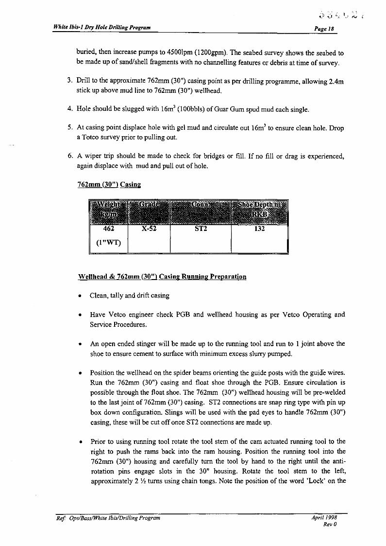
3. Drill to the approximate 762mm (30 n) casing point as per drilling programme, allowing 204m
stick up above mud line to 762mm (30n) wellhead.
4. Hole should be slugged with 16m' (lOObbls) of Guar Gum spud mud each single.
5. At casing point displace hole with gel mud and circulate out 16m' to ensure clean hole. Dropa Totco survey prior to pulling out.
6. A wiper trip should be made to check for bridges or fill. If no fill or drag is experienced,again displace with mud and pull out of hole.
762mm (30") Casing
(1 "WT)
Wellhead & 762mm (30") Casing Running Preparation
• Clean, tally and drift casing
• Have Vetco engineer check PGB and wellhead housing as per Vetco Operating andService Procedures.
• An open ended stinger will be made up to the running tool and run to 1 joint above the
shoe to ensure cement to surface with minimum excess sluny pumped.
• Position the wellhead on the spider beams orienting the guide posts with the guide wires.Run the 762mm (30 n
) casing and float shoe through the PGE. Ensure circulation is
possible through the float shoe. The 762mm (30n) wellhead housing will be pre-welded
to the last joint of 762mm (30n) casing. ST2 connections are snap ring type with pin up
box down configuration. Slings will be used with the pad eyes to handle 762mm (30n)
casing, these will be cut off once ST2 connections are made up.
• Prior to using running tool rotate the tool stem of the cam actuated running tool to theright to push the rams back into the ram housing. Position the running tool into the
762mm (30n) housing and carefully turn the tool by hand to the right until the anti
rotation pins engage slots in the 30n housing. Rotate the tool stem to the left,approximately 2 Y, turns using chain tongs. Note the position of the word 'Lock' on the
Ref Ops/BasslWhite Ibis/Drilling Program Apri/1998Rev 0
White lbis-l Dry Hole Drilling Program
~ 3 '1 (\ ." \.~Y L ~,' f.,., '--~
Page 19
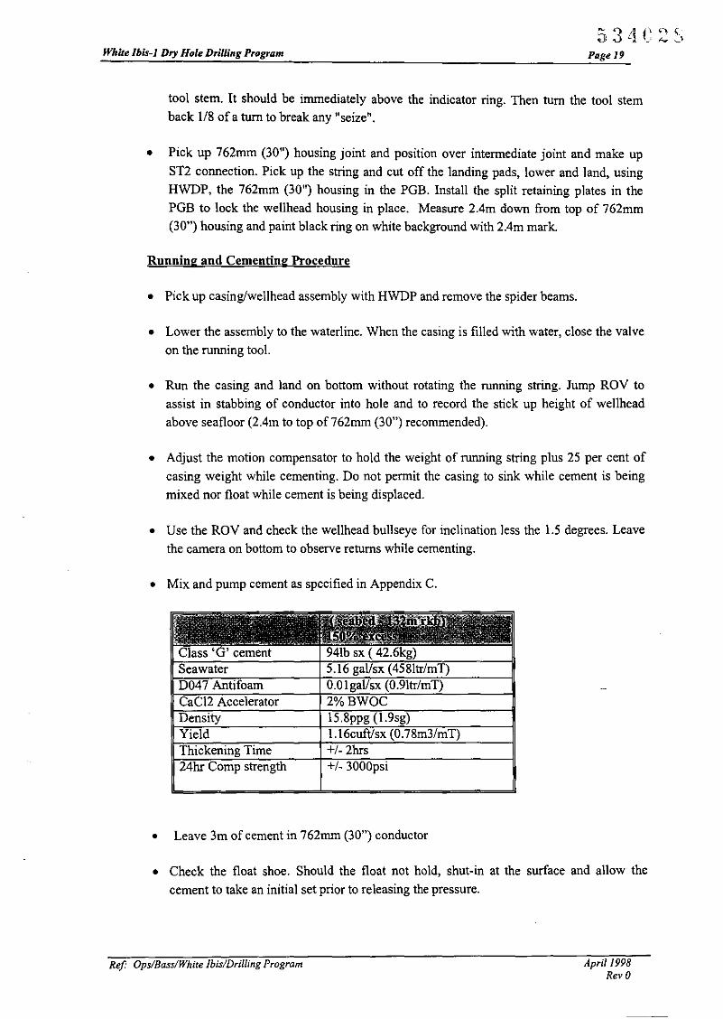
tool stem. It should be immediately above the indicator ring. Then turn the tool stem
back 1/8 of a turn to break any "seize".
• Pick up 762mm (30") housing joint and position over intermediate joint and make up
ST2 connection. Pick up the string and cut off the landing pads, lower and land, using
HWDP, the 762mm (30") housing in the PGB. Install the split retaining plates in the
PGB to lock the wellhead housing in place. Measure 2.4m down from top of 762mm
(30") housing and paint black ring on white background with 204m mark.
Running and Cementing Procednre
• Pick up casing/wellhead assembly with HWDP and remove the spider beams.
• Lower the assembly to the waterline. When the casing is filled with water, close the valve
on the running tool.
• Run the casing and land on bottom without rotating the running string. Jump ROV to
assist in stabbing of conductor into hole and to record the stick up height of wellhead
above seafloor (204m to top of 762mm (30") recommended).
• Adjust the motion compensator to hold the weight of running string plus 25 per cent of
casing weight while cementing. Do not permit the casing to sink while cement is being
mixed nor float while cement is being displaced.
• Use the ROV and check the wellhead bullseye for inclination less the 1.5 degrees. Leave
the camera on bottom to observe returns while cementing.
• Mix and pump cement as specified in Appendix C.
lass 'G' cementSeawaterD047 AntifoamCaCI2 AcceleratorDensityYieldThickening Time24hr Comp strength
941b sx ( 42.6kg)5.16 gallsx (458Itr/mT)0.0 I gal/sx (0.9Itr/mT)2% BWOC15.8ppg (1.9sg)1.16cuftisx (0.78m3/mT)+/- 2hrs+/- 3000psi
• Leave 3m of cement in 762mm (30") conductor
• Check the float shoe. Should the float not hold, shut-in at the surface and allow the
cement to take an initial set prior to releasing the pressure.
Ref Ops/Bass/White Ibis/Drilling Program April 1998Rev 0

White Ibis-I Dry Hole Drilling Program
534C2DPage 10
• Back off the running tool, by rotating to the right approximately 2 Y, turns. When tool
disengages or releases from wellhead housing the compensator will stroke closed. Pick up
carefully until stinger is clear ofwellhead housing and pull out of the hole.
Ref Ops/BasslWhite Ibis/Drilling Program April 1998Rev 0

White Ibis-J Dry Hole Drilling Program
Materials & Equipment for 914mm (36") hole.
53 11C30PagelJ
Item Description Q!yI Vetco housing assembly, 762mm (30") with full 762mm (30") x 1.5" WT 1
casing joint wI ST-2 box down2 762mm (30") x 1"WT intermediate joint with ST-2 pin up and ST -2 box down 33 762mm (30") x 1"WT shoe joint with ST-2 pin up and single valve float shoe 1
down4 Vetco SG-5 Permanent Guide base, removable, plates & studs 15 Slope indicator on PGB 16 Bit 660mm (26") 1-1-1 withjets 17 Bit breaker plate, 660mm (26") 18 914mm (36") four arm hole opener with jets 19 Drill collars 8",6 5/8" b x p reg conns. 910 O-ring for 762mm (30") running tool 111 Rig positioning equipment 1 set
ReI Ops/Bass/White Ibis/Drilling Program April 1998RevO
White Ibis-! Dry Hole Drilling Program
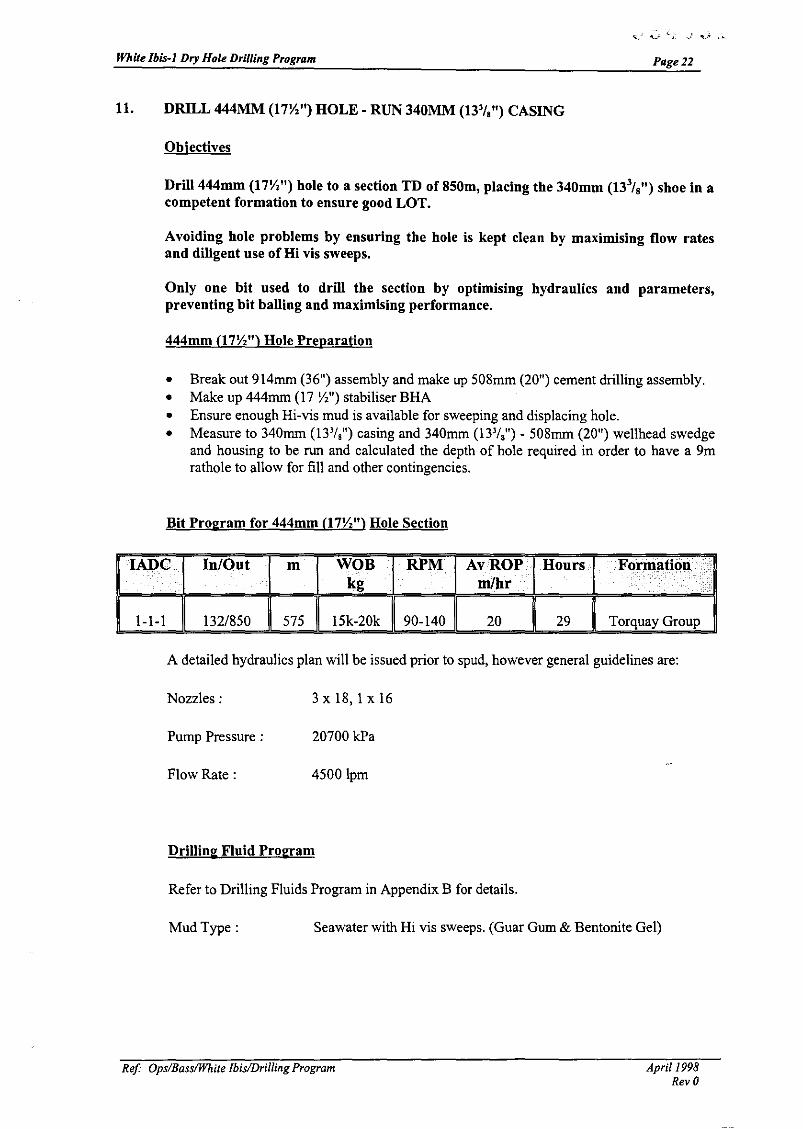
11. DRILL 444MM (17Y.") HOLE - RUN 340MM (13'1,") CASING
Objectives
Page 22
Drill 444mm (17Y.") hole to a section TD of 850m, placing the 340mm (133/ 8") shoe in a
competent formation to ensure good LOT.
Avoiding hole problems by ensuring the hole is kept clean by maximising flow ratesand diligent use of Hi vis sweeps.
Only one bit used to drill the section by optimising hydraulics and parameters,preventing bit balling and maximising performance.
444mm (l7Y.") Hole Preparation
• Break out 914mrn (36") assembly and make up 508mm (20") cement drilling assembly.• Make up 444mrn (17 Y,") stabiliser BHA• Ensure enough Hi-vis mud is available for sweeping and displacing hole.• Measure to 340mrn (13'1,") casing and 340mrn (13'1,") - 508mrn (20") wellhead swedge
and housing to be run and calculated the depth of hole required in order to have a 9mrathole to allow for fill and other contingencies.
Bit Program for 444mm (l7Y.") Hole Section
lADe
1-1-1
InlOut
132/850
m
575
WOBkg
15k-20k
RPM AvROP Hoursmlb.r .
90-140 20 29
Formationl
Tmq~YGro;lA detailed hydraulics plan will be issued prior to spud, however general guidelines are:
Nozzles:
Pump Pressure:
Flow Rate :
3 x 18, I x 16
20700 kPa
4500lpm
Drilling Fluid Program
Refer to Drilling Fluids Program in Appendix B for details.
Mud Type: Seawater with Hi vis sweeps. (Guar Gum & Bentonite Gel)
Ref' Ops/BassIWhite Ibis/Drilling Program Apri/!998Rev 0

White Ibis-I Dry Hole Drilling Program
444mm fl7Y,") Hole Recommended BHA
Pagel3
Component SizeOD Number Approx. Commentsmm length
Bit 444 I 0.517 y," NBS wlfloat 444 I 1.0
Anderdrift 203 I 2.54 65/8" Reg8" ponyNMDC 203 I 3.0
17 \'," String Stab 444 I 2.4 6 5/8" RegTotco ring I -8"NMDC 203 I 9.4
17 Y," String Stab 444 I 2.4 6 5/8" Reg8"DC 203 6 56.4
Jar 203 I 3.08"DC 203 3 28.2X/O 203 I 0.7 6 5/8" Reg x NC50
HWDP 127 I 9.4HDIS I
BHA Total 118.94 mHWDP 127mm 8 75.2m
This BHA will be used to drill out the 762mm (30") shoe with 660mm (26") bit and then todrill the 444mm (17\',") hole section.
Survey Program
Anderdrift throughout section.
Electronic Multi-shot survey at section TD.
Potential Drilling Hazards
Hazard•••••••••
Solution LComment• ••
Drag I Bridging Hole should be slugged with 5m' (35bbls) ofviscous mud prior to making connections. Increaseslug size ifproblem not resolved.Wiper Trip at section TD I ream if necessary
660 mm (26") Cement Drilling Procedure
I. RIH with 660m (26") cement drilling assembly and tag cement. Record the depth, drillout of the 762mm (30") casing using low parameters and circulating with seawater. Drill
new formation. Work bit through drilled out float shoe.
2. Make up 18 3/4" wellhead & running tool clw cement plugs and stand back in derrick.Lower the running tool into the high pressure wellhead housing, rotate the tool stem to
the left approximately five times until it stops (lock), do not force. Verify that the word'lock' is just visible above the housing. Run on HWDP
3. POOH and lay down 660mm (26") bit and pick up 444mm (l7Yz") bit.
ReI Ops/Bass/White Ibis/Drilling Program April/998Rev 0

White Ibis·] Dry Hole Drilling Program
444mm (17\1,") Drilling Procedure
1. RIH with 444mm (17 \1,") BRA tag new fonnation.
Page 24
2. When string stabiliser is out of shoe drill using parameters shown above with hi vis mud
sweeps and seawater with returns to seabed. Slug a 5m3 (35bbls) viscous Guar Gummud pill every single.
3. Drill to the section TO as calculated.
4. At section TO displace hole with a weighted gel mud 1.14sg.
5. A wiper trip should be made to check for bridges or fill. If no fill or drag is experienced,
run back to bottom, check for fill, drop EMS and pump BHA out carefully ensuring hole
stays full of weighted mud. Pump rate should be sufficient to keep hole full and nomore.
340mm (13 '/~ Casing
101 L80 NewVAM 850 14400 15900 17400
Centraliser Placement ;- 2 per joint for shoe track and I per two joints up to 700 m R.KB
340mm (13 '/~ Casing Running Preparation
• Clean, tally and drift casing.
• Paint 340mm (13'/,") shoe white to aid identifying the location of the shoe on TV while
stabbing into the 762mm (30") housing. Soft line guides to be attached to the float shoe
to aid stab in.
• Prior to using running tool rotate the shaft of the running tool to the right (unlock) and
push the dogs into place.
Running and Cementing Procedure
• Bakerlok the threads on the shoe track.
• Run a string of 340mm (13'/,") 00 10lkglm casing with New VAM connectors.
• Fill the casing with water as run. Ascertain that circulation is possible through the shoe.
ReI Ops/Bass/White Ibis/Drilling Program April 1998Rev 0
While Ibis-] Dry Hole Drilling Program PagelS
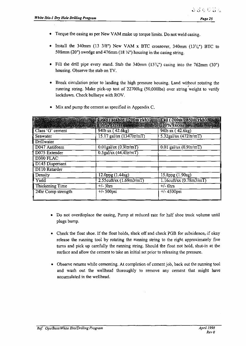
• Torque the casing as per New VAM make up torque limits. Do not weld casing.
• Install the 340mm (13 3/8") New VAM x BTC crossover, 340mm (13'/,") BTC to
508mm (20") swedge and 476mm (18 \4") housing in the casing string.
• Fill the drill pipe every stand. Stab the 340mm (13'/,") casing into the 762mm (30")housing. Observe the stab on TV.
• Break circulation prior to landing the high pressure housing. Land without rotating theJ
running string. Make pick-up test of 22700kg (50,OOOlbs) over string weight to verify
lockdown. Check bullseye with ROV.
• Mix and pump the cement as specified in Appendix C.
Class 'G' cementSeawaterDrillwaterD047 AntifoamD075 ExtendermOOFLACDl45 DispersantD 110 RetarderDensityYieldThickening Time24hr Comp strength
94lb sx ( 42.6kg)15.17 gal/sx (1347Itr/mT)
O.Olgal/sx (0.91tr/mT)O.5gal/sx (44.4ltr/mT)
12.0ppg (l.44sg)2.55cuft/sx (1.69m3/mT)+/- 3hrs+/- 500psi
Yo941b sx ( 42.6kg)5.32gal/sx (472ltr/mT)
om gal/sx (0.91tr/mT)
15.8ppg (1.90sg)1.16cuftlsx (0.78m3/mT)+/- 6hrs+/- 4500psi
• Do not overdisplace the casing, Pump at reduced rate for half shoe track volume until
plugs bump.
• Check the float shoe. If the float holds, slack off and check PGB for subsidence,· if okay
release the running tool by rotating the running string to the right approximately five
turns and pick up carefully the running string. Should the float not hold, shut-in at the
surface and allow the cement to take an initial set prior to releasing the pressure.
• Observe returns while cementing. At completion of cement job, back out the running tool
and wash out the wellhead thoroughly to remove any cement that might have
accumulated in the wellhead.
Ref OpsiBasslWhile IbislDrii/ing Program April /998Rev 0

White Ibis-I Dry Hole Drilling Program
Materials & Equipment for 444mm 07 Y, II) hole.
53·1C3SPage 26
Item Description Q!yI Vetco 18 %" high pressure wellhead housing with housing extension I
508mrn(20") x 1"WT crossed over 13 3/8" BTC pin down2 340mrn (13 3/8") BTC box to 340mrn (13 3/8") New VAM pin crossover 13 340mrn (133/8") 101kglm L80 New VAM Casing 644 340mrn (13 3/8") 101kg/m L80 New VAM Casing shoe joint 15 340mrn (13 3/8") 101kg/m L80 New VAM Casing collar joint 16 Centralisers 340mrn (13 3/8") bow type 107 660mrn(26")bit,I-I-1 18 444mrn (17 y,") bit 1-1-1 withjets 19 Bit breaker plate 660mm 110 Bit breaker plate 444mrn I11 Anderdrift 8", with 6 5/8" reg conns. 112 NMDC 8" + 2 * 8" ponyNMDC I13 444mrn (17 y,") string stabiliser 214 8" drilling jars 315 Klampon protectors 444mm 316 Running tool for high pressure wellhead housing I
17 AX gasket 218 O-ring for 18 %" wellhead housing running tool spare 1
19 Wear bushing for 18 %" housing 120 Combination running and testing tool for running WB and testing 18 %" I
housing22 O-ring for running and testing tool I23 Tam packer with 340mrn (13 3/8") element 124 Hevi Wate DP 5" 30
Ref Ops/BasslWhite Ibis/Drilling Program April 1998Rev 0

White Ibis-! Dry Hole DriUing Program
12. DRILL 311MM (12'1.") HOLE - RUN 244MM (9'1,") CASING
Objective
- 3 j~ l\ ~-. {:.J! ,t..J {j v U
Page 27
• Minimise formation damage through good mud mauagement and trippingpractices i.e. avoiding the need to back ream.
• Minimise open hole exposure by drilling as quickly and safely as possible.• Achieve good hole quality for extensive wireline logging program.
Function Testing the BOP stack
Ram position to be as follows, top down:- Blind/shear, 127mm (5") pipe, Variable bore,l27mm (5") Pipe.
Function test BOP's prior to running. Note gallons to function and closing time.
Complete the BOP test and inspection affidavits and send to shore for filing.
Running the Stack and Riser
The pressure and function test will be completed outside the critical path. Other preparations
for running the BOP will proceed simultaneously in order to have the stack ready to run as
soon as possible after cementing the 340mm (13'/,") casing,
• Position the BOP stack on the spider beams. Insert the guide lines in the posts of the BOP
stack.
• Install and lock the lower marine riger package onto the 476mm (18 %") BOP stack with
a new standard AX ring gasket.
• Install a new standard AX ring in the wellhead connector. Clean and grease with proper
lubricant. Function test all preventers, failsafe valves, and the WH connector from both
pods while BOP is sitting on spider beams.
• Insert the guide lines in the marine riser guide frame.
• Place the marine riser handling spider on the rotary table.
• Pick up a double joint of marine riser that has been previously racked back in the derrick
using the marine riser handling sub. Lower the marine riser joint through the marine riser
handling spider and make up to top of the ball joint.
• Pick up the BOP stack, remove the spider beams and lower the marine riser joint until it
can be landed on the marine riser handling spider. Continue to run the marine riser
spacing out as necessary. Test the choke and kill line to 34.5MPa (5000psi), as run.
Ref Ops/BassIWhite Ibis/Drilling Program April 1998Rev 0

White Ibis-I Dry Hole Drilling Program Page2S
• Pick up the telescopic joint (locked in the closed position) and attach to the nser
assembly.
• Remove the pins that lock the slip joint in the closed position.
• Stroke out the slip joint inner barrel and pick up entire assembly. Remove the marine riser
handling spider and the lower slip joint through the rotary table until the riser tensioning
cables can be installed on the riser tensioning ring on the outer barrel of the slip joint.
Adjust the tension on the cables to support approximately 125 percent of the weight of
the marine riser.
• Install the air operating line to the slip joint packing gland; 5 to 10 psi (34kPa - 68kPa) is
normally sufficient pressure to maintain an effective seal against the hydrostatic head of
the drilling fluid. Install the choke line to the terminal fitting on the slip joint. Install the
diverter package.
• Tension the guide wires for landing the BOP stack.
• Lower the riser and the BOP stack until the wellhead connector of the BOP stack is
landed in the wellhead housing. Observe the landing with the TV.
Note: The wellhead connector should be open when the connector is on the spider beams and
the control valve maintained in the open position until it is landed on the wellhead housing.
Lock the BOP stack on the wellhead housing with 10.3MPa (150Opsi). A pick up test of
22.6k kg (50,000lbs) above stack weight should be performed to ensure the connector is
latched.
• Land and lock the diverter housing.
• Reduce the tension in the guide wires to 34.4MPa (5000psi). Set riser tension to +1- l8.lk
kg (40,000Ibs).
• Run in hole and land test plug. Test BOPs to 3.4/34.4 MPa (500/5000psi) for 5/10minutes. Re-check permanent datum (top of 476mm (18 'I.") housing) and ram space out
with painted test joint.
• Run the 476mm (18%") nominal seat protector.
• Prior to drilling out cement, close the diverter bag on the drill pipe and function test the
system. Check and record choke line friction and check hang off space out. Perform
hang-off on second pipe rams from the bottom.
311mm (12'1.") Hole Preparation
• Break out 444mm (17Yz") BHA and make up 311mm (12 Y.") drilling assembly• Install the 476mm (18%") BOP stack and marine riser• Pressure test the BOP stack on the test stump
Ref Ops/BasslWhite Ibis/Drilling Program April 1998Rev 0

White Ibis-I Dry Hole Drilling Program
'- ,'\ '.~) 0 ~~: I_i ..j __l
Page 29
• Ensure adequate mud is mixed to drill the section• Measure 244mm (9'1,") casing and wellhead housing to be run and calculated the depth
of hole required in order to have a 9m rathole to allow for fill and other contingencies.• Test the casing against the blind/shear ram to 7MPa (IOOOpsi) prior to drilling out.• Pump through choke and kill line at 45 and 90 SPM to measure the circulating pressure
loss. Record along with mud weight.• Remove lock down ring from 244mm (9 5/8") hanger.
Well Control
The following abnormal pressure indicators will be monitored below surface casing :-
DxC exponent
Cuttings morphology in shales
Gas Levels
ROP
Mud properties
Conduct well control drills routinely in line with Northern Offshore policy & procedures and
the Petroleum (Submerged Lands) Act
Test BOP's after setting each casing string or every 14 days operations.
Run and report slow pump rates daily.
Bit Program for 311mm (12'1.") Hole Section
lADe InlOut m WOBi. RPM AvROP Hours Formation y
kg rWhr••••••••
BD447 850/2150 1300 8-15k 12/140 15 50 Torquay, DemonsBluff, Eastern
View CoalMeasures EVCM
BD447 is a Hughes Christensen Black Diamond PDC bit
A detailed hydraulics plan will be issued prior to spud.
Ref Ops/Bass/While Ibis/Drilling Program April 1998Rev 0

White lbis-J Dry Hole Drilling Program
Drilling Fluid Program
Refer to Drilling Fluids Program in Appendix B for details.
Freshwater KCII PHPN Polymer
Page 30
5 or as hole +1- 9
conditions
dictate
311mm (12'1.") Hole Recommended BHA
<6%
vlv<71.5 6-8
Component SizeOD Number Approx. Commentsmm length
12 V."Bit 311 I 0.512 v." NBS wlfloat 203 I 1.0
8" Anderdrift 203 I 2.54 65/8" Reg8"ponyNMDC 203 I 3.0
12 v." String Stab 311 1 2.4 6 5/8" RegTotco ring 1 -8"NMDC 203 1 9.4
12 v." String Stab 311 1 2.4 6 5/8" Reg8"DC 203 6 56.4
Jar 203 1 3.08"DC 203 3 28.2X/O 203 1 0.7 6 5/8" Reg x NC50
HWDP 127 1 9.4HDIS 1
BHA Total 118.94 mHWDP 127mm 8 75.2 m
_.
Survey Program
Anderdrift throughout section.Electronic Multi-shot survey at section TD.
Ref Ops/Bass/White Ibis/Drilling Program April 1998Rev 0
White lbis-l Dry Hole Drilling Program
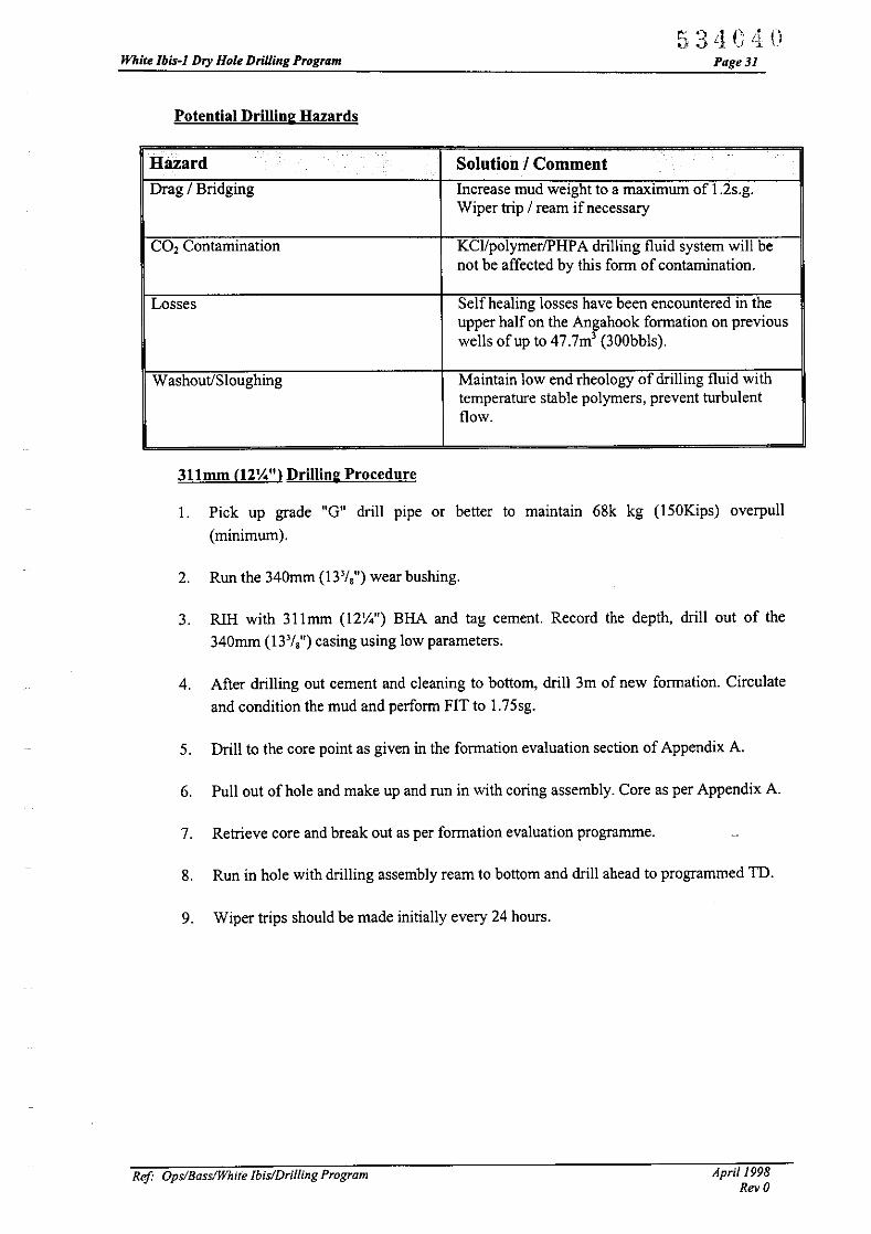
Potential Drilling Hazards
534C LIOPage3l
Hazard .. Solution I CommentDrag 1Bridging Increase mud weight to a maximum of 1.2s.g.
Wiper trip 1ream ifnecessary
CO, Contamination KCl/polymer/PHPA drilling fluid system will benot be affected by this form of contamination.
Losses Self healing losses have been encountered in theupper half on the Angahook formation on previouswells of up to 47.7mJ (300bbls).
Washout/Sloughing Maintain low end rheology of drilling fluid withtemperature stable polymers, prevent turbulentflow.
311mm (12\4") Drilling Procedure
I. Pick up grade "G" drill pipe or better to maintain 68k kg (I50Kips) overpull
(minimum).
2. Run the 340mm (13'/8") wear bushing.
3. RIH with 311mm (12\4") BHA and tag cement. Record the depth, drill out of the
340mm (13'/8") casing using low parameters.
4. After drilling out cement and cleaning to bottom, drill 3m of new formation. Circulate
and condition the mud and perform FIT to 1.75sg.
5. Drill to the core point as given in the formation evaluation section of Appendix A.
6. Pull out of hole and make up and run in with coring assembly. Core as per Appendix A.
7. Retrieve core and break out as per formation evaluation programme.
8. Run in hole with drilling assembly ream to bottom and drill ahead to programmed TD.
9. Wiper trips should be made initially every 24 hours.
Ref' Ops/BassIWhite lbis/Driiiing Program Aprill998Rev 0
White Ibis-I Dry Hole Drilling Program
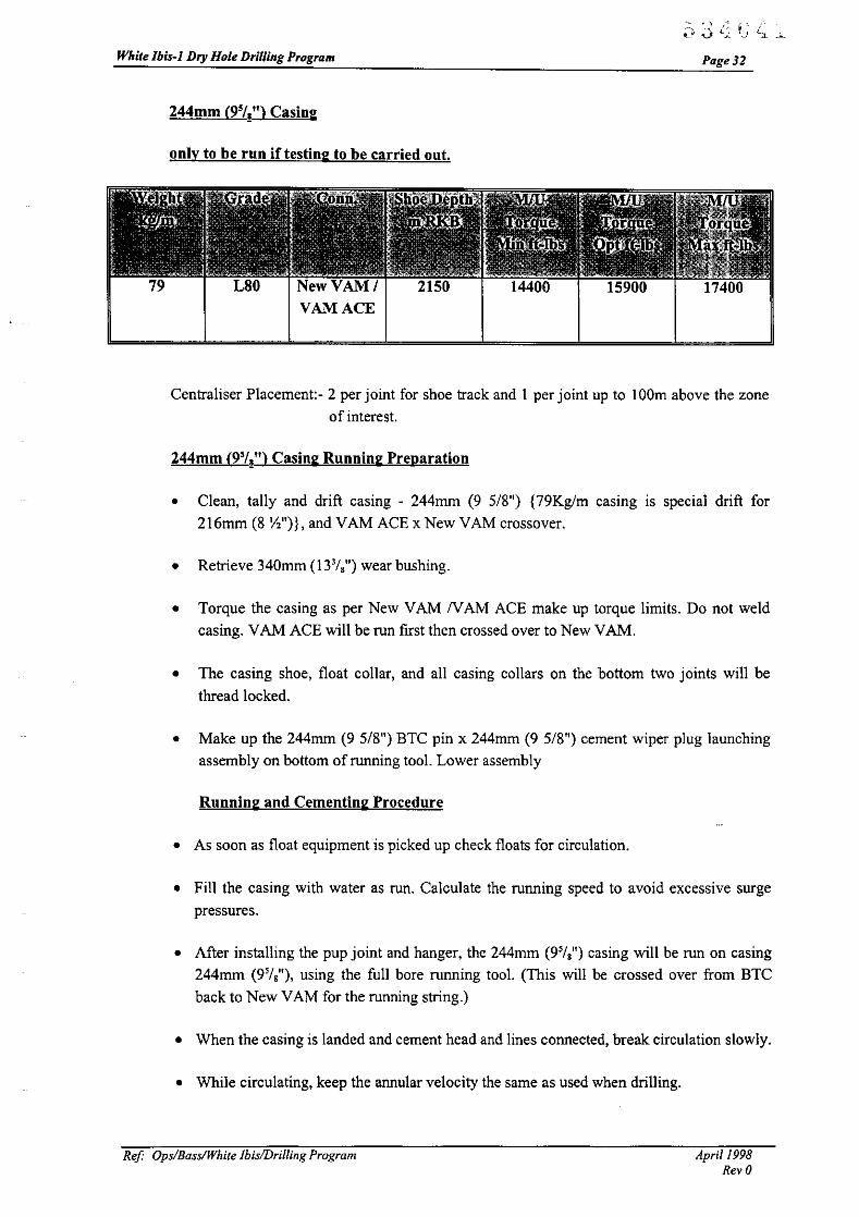
244mm (9'lt) Casing
only to be run if testing to be carried out.
14400 15900
.~ ., ..1 • ,. :
~y .,) lj t~! L:t ~
Page 31
17400
Centraliser Placement:- 2 per joint for shoe track and I per joint up to 100m above the zone
of interest.
244mm (9'lt) Casing Running Preparation
• Clean, tally and drift casing - 244mm (9 5/8") {79Kg/m casing is special drift for216mm (8 Yz")}, and VAM ACE x New VAM crossover.
• Retrieve 340mm (13 3/,") wear bushing.
• Torque the casing as per New VAM N AM ACE make up torque limits. Do not weldcasing. VAM ACE will be run first then crossed over to New VAM.
• The casing shoe, float collar, and all casing collars on the bottom two joints will be
thread locked.
• Make up the 244mm (9 5/8") BTC pin x 244mm (9 5/8") cement wiper plug launchingassembly on bottom of running tool. Lower assembly
Running and Cementing Procedure
• As soon as float equipment is picked up check floats for circulation.
• Fill the casing with water as run. Calculate the running speed to avoid excessive surgepressures.
• After installing the pup joint and hanger, the 244mm (9'/,") casing will be run on casing244mm (9'/,"), using the full bore running tool. (This will be crossed over from BTC
back to New VAM for the running string.)
• When the casing is landed and cement head and lines connected, break circulation slowly.
• While circulating, keep the annular velocity the same as used when drilling.
Ref Ops/Bass/White Ibis/Drilling Program April 1998Rev 0

White Ibis-] Dry Hole Drilling Program
• Mix and pump cement as per Appendix C.
534CL1;~Page 33
Class 'G' cementSeawaterDrillwaterD047 AntifoamD075 ExtenderD300FLACDI45 DispersantD II 0 RetarderDensityYieldThickening Time24hr Comp strength
94 b sx ( 42.6kg)9.75 gal/sx (865Itr/mT)
O.Olgal/sx (0.9Itr/mT)0.35gal/sx (31.1ltr/mT)
0.25gal/sx (22.2Itr/mT)13.2ppg (1.58sg)1.86cuftlsx (1.24m3/mT)+/- 5.5hrs+/- 1000psi
3.99gal/sx (354Itr/mT)0.03 gal/sx (2.7Itr/mT)
0.90gal/sx (79.9Itr/mT)0.25gal/sx (22.2Itr/mT)0.03gal/sx (2.7Itr/mT)15.8ppg (1.90sg)1.16cuftlsx (0.78m3/mT)+/- 4hrs+/- 4200psi
• Do not overdisplace the casing, Pump at reduced rate for half shoe track volume until
plugs bump. Check the float.
• Observe returns while cementing. At completion of cement job, back out the running tool
and wash out the wellhead and BOP's thoroughly to remove any cement that might have
accumulated in the wellhead, BOP's or riser.
Setting and Testing the 244mm (9'/~ Seal Assembly
• Have wellhead service engineer on board to set 244mm (9'/,") seal assembly. Run on
203mm (8") drill collars and HWDP. Have spare seal on board.
• Test seal assembly to 34.5MPa (5000psi). Do not collapse the 244mm (9'/,") casing.
• Test the BOP stack and choke manifold to 34.5MPa (5000psi), and the annular to
17.6MPa (2500psi) prior to cleaning out the 244mm (9'/,") casing.
Testing
The testing programme will be issued separately.
Ref Ops/Bass/White IbislDriliing Program April 1998Rev 0

.~ ~) ,; I: L'l.~ V '-). ~. .t L'White Ibis-I Dry Hole Drilling Program Page 34
Materials & Equipment for 311mm (12 '/.i") hole.
Item Description Q!yI Vetco casing hanger 18 %" x 244mm ( 9 5/8") made up on a pup joint of I
244mm ( 9 5/8") New VAM casing
2 Vetco full bore running tool for 18 %" x 244mm ( 9 5/8") casing hanger with I
244mm (9 5/8") BTC box up
3 O-ring for 18 %" x 244mm ( 9 5/8") full bore running tool I
4 Vetco seal assembly, torque set for 244mm (95/8") casing I
.5 O-ring for 244mm (9 5/8") seal assembly I
6 Running tool for seal assembly I
7 Test tool, lands in 244mm ( 9 5/8") seal assembly I
8 Wear bushing, 18 %" x 244mm (95/8") for torque set seal assembly I
9 244mm (9 5/8") 79kg/m L8D Special drift VAM ACE shoe joint I
ID 244mm (9 5/8") 79kg/m L8D Special drift VAM ACE collar joint I
11 244mm (9 5/8") 79kg/m L8D Special drift VAM ACE casing I
12 244mm (9 5/8") 79kg/m L8D Special drift VAM ACE casing 175
13 244mm (9 5/8") 79kg/m L8D Special drift New VAM box x VAM ACE pin I
crossover
14 244mm (9 5/8") 79kg/m L8D Special drift New VAM box x BTC pin I
crossover
IS Centralisers, bow type 55
16 Klampon protectors 244mm I
17 Tam packer with 244mm (9 5/8") element I
18 311mm (12 '/.i") bits 4
19 Bit breaker plate 311mm I
2D Anderdrift 8", with 6 5/8" reg coons. 1
22 NMDC8" 1
23 311mm (12 '/.i") string stabiliser 3
24 8" drilling jars 3
25 Sidetrack package I set
26 Fishing tools as req'd
27 Surface plug set equipment including ball and dart launching manifold I
Ref OpslBasslWhite IbislDril/ing Program April /998Rev 0

APPENDIX A
GEOLOGY SUMMARY
&
FORMATION EVALUATION
53 '1("'1It L. j Ll'::..t

While Ibis-I Dry Hole Drilling Program
CONTENTS
1. WELL OBJECTIVES
2. GEOLOGY
2.1. General
2.2. Structure
2.3. Reservoir Stratigraphy
2.4. Predicted Section
2.5. Mud Logging
3. CONVENTIONAL WIRELINE LOGGING
3.1. Wireline Logging & Testing Program
3.2. VSP Data Processing
3.2.1. Air Consumption
3.2.2. Downhole receiver
4. LOGGING WIDLE DRILLING (LWD)
5. PROPOSED CORING PROGRAM
5.1. Objectives
5.2. Intended Core Intervals
5.3. Correlation and coring guidelines
5.4. Core 1
5.5. Post Coring
6. DATA DISTRIBUTION
6.1. Cuttings
6.2. Cores
6.3. Geochemistry Samples
6.4. Sidewall Cores
6.5. Wireline Logs
6.6. Mudlog
6.7. Hydrocarbon Samples
7. REPORTING REQUIREMENTS
7.1. Geological
7.1.1. Geological Reporting
7.1.2. Mud Logging and Wireline Logs
r:;3'1i'~~:Ui /.. . ' ..j L1: tJ
1
1
1
1
2
2
2
3
4
5
5
6
6
6
6
6
6
7
7
7
7
7
7
7
8
8
8
9
9
9
9
FIGURES
APPENDICES
ENCLOSURES
Ref Ops/BassIWhite Ibis/Final Geoprog.doc April 1998

Geological Prognosis White Ibis. Bass Basin
1. WELL OBJECTIVES
Pagel
The primary objective of White Ibis 1 is to evaluate a series of Late Cretaceous to
Palaeocene intra Eastern View Coal Measures (ECVM) stacked shoreline and delta plain
reservoir seal couplets in a fault dependent closure situated over a basement high west ofthe Yolla Trough
The secondary objective of the well is to test a fault dependent structural closure at the Top
ECVM top-sealed by the Late Eocene Demons Bluff Formation.
2. GEOLOGY
2.1. General
The White Ibis 1 well is to be drilled approximately 45 metres updip and
approximately 4300 metres northwest along strike from Bass-3, an exploration well
drilled by Esso in 1967. Bass-3 was plugged and abandoned after a Formation
Integrity Test (FIT) recovered 29cf of gas, 800cc of condensate and 12259cc ofdiscoloured water.
2.2. Structure
The basement high over which the White Ibis prospect lies formed during Early
Cretaceous rifting between the Australian and Antarctic plates. During and post
deposition of the overlying EVCM sediments, drape, compaction and growth
faulting comprised the major mechanisms forming the positive structural feature at
White Ibis.
Seismic data acquired since the drilling of Bass-3 has produced improved images at
depth. These data have revealed that Bass-3 was drilled "off structure" leaving
approximately 45 metres of updip potential at White Ibis.
In the Palaeocene primary target, seismic reflection data over the White Ibis
structure has revealed distinct amplitude, AVO and acoustic impedance anomalies
at an equivalent stratigraphic level to the FIT in Bass-3. Additionally, the AVO
anomaly appears to conform with the structure suggesting that the anomaly could
be a DH!.
Fault - seal analysis on the major bounding fault has been undertaken at White Ibis.
Calibration with data from Yolla suggests a high probability that the White Ibis
fault is sealing.
The smaller, secondary target at White Ibis has been mapped as a fault-independent
four way dip closure at the Top EVCM. Hydrocarbons have been encountered at
this level in both Cormorant-l in T/18P and Yolla-l in the adjoining TIRLI permit.
Ref OpsiBasslWhile Tbis/Final Geoprog.doc April/998
Geological Prognosis White Ibis, Bass Basin
2.3. Reservoir Stratigraphy
Pagel
The primary reservoir targets at White Ibis-l are the shoreface and fluvial
sandstone beds of the Palaeocene and Late Cretaceous Eastern View CoalMeasures.
The intra-EVCM sands were deposited in a combination of terrestrial and shoreface
subaqueous/subaerial environments. Therefore, sand development and reservoirquality and continuity constitute significant risks in the Bass Basin. While it is
possible to correlate regional sand trends within a gross sequence at the objective
level, poor well control and the depositional history of individual sand packagesmakes correlation difficult at smaller scales.
AMOCO in 1987 interpreted logs and core from the Late Cretaceous and
Palaeocene reservoir sands at Bass-3 to be interbedded lacustrine or estuarine silts,
shales and channel sands overlain by stacked shoreface, delta plain channels,
crevass splay and marsh sequences. These interbedded channel and shoreface
sands and shales have an average porosity of 20% and measured perrneabilities
ranging from <lmd to >300md and represent a series of stacked reservoir/seal
couplets analogous to the stacked reservoirs found at Yolla-l.
The sediments present at the Top EVCM in Bass-3 were interpreted to have been
deposited in a lower to upper shoreface setting. Porosity and permeability
measured from core at this level in Bass-3 shows an average porosity of 25% and
permeability ranging from <1 to >250 md.
Reservoir risk is considered to be low at White Ibis-l based on core data and the
FIT recovery of hydrocarbons at Bass-3. Evidence of the lateral continuity of
major sand and shale packages, albeit showing variances in thickness and reservoir
quality across the basin, is demonstrated by correlation between Bass-3,
Koorkah- 1, Aroo-l, Yolla-l and Tilana-l (Figure 1).
2.4. Predicted Section
See accompanying Figure 2.
2.5. Mud Logging
Geoservices will provide a state of the art computerised mudlogging and engineering data
acquisition service comprising a data engineer and mud logger on each 12 hour tour.
Services will include:-
• A full well pressure monitoring service
• Continuous monitoring of drilling and geological parameters
ReI Ops/Bass/White Ibis/Final Geoprog.doc April 1998

Geological Prognosis White Ibis. Bass Basin
• Calculated data analysis as required
• Daily and interval reporting
• Logs and graphs of drilling parameters vs time and/or depth
Page 3
• Mudlog to be electronically transmitted in digital form on a daily basis to Premiers Perth
office
Drilling parameters only will be recorded down to the 13.3/8" casing shoe at approximately
850m MD. Cuttings will be collected when the BOP's and marine riser are connected prior
to drilling the 121/4" hole.
The mud loggers will bag, pack and distribute the samples as follows:
Sample Hole Section Fre(lUenC~ IT",''ashed ('nnashed \\ashed WashedDistribution (III) (Sets) (Quantit~ ) aud Dried and Dried
(Sets) (Quantit~ )Premier Oil 5m to I 300g I 100gAustralasia 121
/." Hole 1750m I 300g I 100g3mtoTD
Boral I 300g I 100g121
/." Hole as above I 300g I 100g
Mineral I 100gResources 121
/." Hole . not - I 100gTasmania requiredBRS I 100g
121/." Hole - not - 1 100g
required
Additionally one Samplex sample tray will be collected over the above intervals and
retained at the wellsite until the completion of the drilling campaign.
3. CONVENTIONAL WIRELINE LOGGING
It is the intention of the Operator to have a fit for purpose and cost effective wireline
logging program comprising a firm logging package and optional tools for additional
evaluation should they be required. The table below outlines the logging program and the
objectives the Operator hopes to achieve by using these tool combinations. Maximum tool
combinability has been achieved in order to cut down on logging runs and hence rig time.
ReI Ops/BasslWhite Ibis/Final Geoprog.doc April 1998

Geological Prognosis White Ibis. Bass Basin
3.1. Wireline Logging & Testing Program
PROPOSED LOGGING RUNS IF SIGNIFICANT HYDROCARBON SHOWS ARE ENCOUNTERED DURING DRILLING
Logs will be run from TD to the 133/8" casing shoe. The 171/2" hole will be logged behind the 133/8" casing when the final TD logs are run, therefore no
intermediate logging suite is envisaged to be run. Should 95/8" casing be run prior to reaching TD and before intersecting the zones of interest the Operator
proposes to run a PEX-Sonic logging string for intermediate petrophysical data.
FINAL LOGGING SUITE Indicate if Firm or Yolla-2Optional
Run I. PEX-CMR* Firm Conventional logging tools will be used as backup,CMR contingent
Run 2. FMS*-Array Sonic Firm FMS will to obtain structural & stratigraphic dipinformation, sedimentary analysis and depth matching!orientation of cores. Sonic will provide porosity, shearseismic, thin-bed and sand strength information
Objective to obtain baseline formation pressure profileRun 3. Modular Dynamics Formation Tester (MDT)* and Firm in reservoir sands, to confirm hydraulic continuity andNGT* correlation tool to sample zones of interest( up to 40 pressures and 3
samples)
Run 4. VSp* Firm A maxtmum of 50 levels to obtain velocityinformation and time correlation to surface seismicopen hole (could also be run in cased hole if required)
Contingent on core recovery, and/or hydrocarbonRun 5. CST (Sidewall Cores) : Optional evaluation (contact definition) and/or age dating.
Anticipate 30 shots
Ref Ops/Bass/White Ibis/Final Geoprog.doc April 1998

White Ibis-lDry Hole Drilling Program Page 5
*CMR is contingent on its successful use in Yolla-2 and on significant hydrocarbon showsin drilling returns during the drilling of White Ibis. If CMR is not used the Array Sonic willbe combined with the PEX tool.
*FMS will not be run if no significant hydrocarbon shows are encountered during drilling.An SHDT dipmeter tool will be on board the rig for collecting structural dip informationshould it be required. The SHDT tool is part of the Schlumberger contracted "Bundle ofTools"
*MDT a program will be undertaken if significant hydrocarbon shows are encounteredduring drilling. An NGT spectral gamma ray tool may be utilised with the MDT dependingon its usefulness in Yolla-2.
*VSP is contingent on significant hydrocarbon shows. If hydrocarbons are not encountereda simple velocity check shot survey will be conducted.
3.2. VSP Data Processing
VSP data processing will include paper prints of VSP/Synthetic Seismogramcomposite displaying:-
• Corridor stack
• Synthetic Seismogram
• Drift curve
• Drift corrected sonic log
• Density Log
• Reflection Coefficient Log
• Acoustic Impedance Log
• Gamma ray, caliper, resistivity and any other selected log
• T-D listing of drift corrected check shots
Each composite wi1l be displayed in Zero Phase SEG negative. For each phase,three different filter versions are required.
Digital VSP data in SEG-Y format is required and should include the unsealed,
unfiltered, corridor stack and the scaled, filtered corridor stack, with possibly threedifferent filters applied. Digital data in SEG-Y format of the SyntheticSeismogram is also required.
3.2.1. Air Consumption
A G or GI gun array is to be used as the seismic energy source. Air will be supplied fromcompressed nitrogen bottles.
Ref Ops/BassIYolla/Dri//ing Program April /998Rev 0

.)-(:'" .. :-\ 1..,1 •• _
Premier 011 Australia Pty LimitedIACN 075 609 728)4S Ord StrelJI (P.O, Box: 1649)W<?:s,t Pert~ WA 6872
PremierOilAustralasia
FACSIMILE
Telephone 61894804100Facsimilo 61 89324 1212Email @prelTlier;:;r.lJ~.com.iillJ
._-_.•...•........_-------
RRF:eIRe
DATE:
TO:
fROM:
Op.IB..s1DrillinglR,O80/Y012.02/DE/j.BU/MIMT
4 June 1998
Boral Energy ResourcesCalEnergyMineral & Petroleum Ops, VicMineral Resources TasmaniaPremier Oil, SingaporeNothern Explorer TIT
David Evans
Angus Guthrie (08) 8223 1851Jane Duncan 44 171 208 1620Ahmed Nadji (03) 9412 5152Carol Bacon (03) 6233 8338Richard Gray 65 733 7651Company Men! 0015872 3636 683320WeJlsite/Gcologist
NO. OF PAGES: 2(including this pag.t')
SUBJECT: Coring Philosophy Addendum White Ibis-I
Appendix A, page 6 & 7, section 5.2, 5.3-5.4, or the White Tbis Drilling Program has beenmodified in light of the lessons learnt during the Yolla-2 coring program, and sh(luld read:
5.2 Intended Core Intervals
The Operator will utilise an antiwhirl face dis<:harge bit in the coring BHA tominimise corc damage during cutting and optimise core re<:overy. A disposablealuminium inner core barrel will also be used. This will act as a ready made con:transportation system.
One 18 metre core will be cut in he Palaeocene to Early Eocene reservoir sequence ifdeveloped and hydrocarbon hearing in White tbis-I. This sequence (l<:curs over theapproximate interval1950-2lS0m MJ) in Bass-3.
I\. good "hydrocarbon show" is defined here as all interval of at least 4m with cviden<:eof sufficient porosity, penneability, and hydrocarbon saturation that it would be likelyto produce if tested.
5.3 - 5.4 Correlatiun and coring guidelines
Bass-3 offset data will he utilised in choosing coring point. Continuous correlation orWhite Ibis mudlog data with the Bass-3 mudlog and wireline log data should bcmaintained during drilling.

j"\:\'_:"\ 1..,) •• _
2
06/04 '9808:45 NO.797 02/02
The most likely gas bearing reservoir is the Yolla Zone 3 (Z3) Sandstone equivalent.There are approximately 15m of claystone section above the Z3 sand in Bass-3. Theequivalent section in Yolla 1 and 2 was much thicker. The top 13 sands in 13ass-3 ace moreblocky and less interbedded in nature than in Yolla 1 & 2. It is anticipated that a positivedrilling break will occur when entering the top Z3 sand.
Regards
DAVID EVANSOperations Geologist

White Ibis-!Dry Hole Drilling Program Page 6
3.2.2. Downhole receiver
A dual Combinable Seismic Acquisition Tool (CSAT) configuration will be used to recordthe seismic wavefield at predetermined downhole locations. The decoupled sensor moduleof the CSAT prevents the signal distortion inherent in conventional open hole verticalseismic profiling tools.
4. LOGGING WHILE DRILLING (LWD)
LWD tools will not be utilised in White Ibis 1. An Anderdrift MWD tool will beincorporated in the drilling assembly to provide inclination data
5. PROPOSED CORING PROGRAM
5.1. Objectives
The objectives of the coring program are to provide core samples for direct measurement of
reservoir properties using conventional and special core analysis techniques with which to
calibrate electrical log measurements and to provide core for sedimentological analysis.
5.2. Intended Core Intervals
The Operator will utilise an antiwhirl face discharge bit in the coring BRA to minimise
core damage during cutting and optimise core recovery. A disposable aluminium inner
core barrel will also be used, this will act as a ready made core transportation system.
One 18 metre core will be cut in the Palaeocene to Early Eocene reservoir sequence
(ideally the Z3S2973 sand equivalent in Yolla-I if developed and hydrocarbon bearing in
White Ibis-I). This sequence occurs over the interva12053-210Om MD in Bass-3
A "good hydrocarbon show" is defined here as an interval of at least 2m with evidence of
sufficient porosity, permeability, and hydrocarbon saturation that it would be likely to
produce if tested.
Bass-3 offset data will be utilised in choosing coring point.
5.3. Correlation and coring guidelines
Continuous correlation of White Ibis mudlog data with the Bass-3 mudlog and wireline log
data should be maintained during drilling.
The proposed cores are described below, however if correlation with Bass-3 is poor or if
sandstones are poorly developed at the proposed coring points there may be a need to
modify the objectives of the coring program as drilling progresses.
ReI Ops/BassIYoJla/Drilling Program April !998RevO

White Ibis-1Dry Hole Drilling Program
5.4. Core 1
>v ~-" .'1 (\ ...- 1;) ,j '1 _' ;) .c.l
Page 7
Coring of the S2973 sandstone should commence after drilling 8-10 metres of thesandstone and establishing the presence of a good hydrocarbon show. If the S2973
sandstone is absent or poorly developed a core should be taken in the next hydrocarbonbearing sandstone with good shows, if developed.
5.5. Post Coring
Once the core is cut, brought to the surface, marked up and cut into 1 metre sections,
the wellsite geologist can take rock chips from each end of the core for lithological
and show evaluation, after which the core will be "resinated". Non fluorescing resin
is poured down the annulus of the 1 metre sections to further stabilise the core for
transportation and reduce fluid evaporation.
The core will then be carefully packed and shipped in a normal sea container as soon
as possible to the Operator's shore base facility for forward air freighting to the
Operators Core analysis Laboratory in Perth
6. DATA DISTRIBUTION
6.1. Cuttings
Sets of cuttings will be distributed at the conclusion of drilling. Addresses will be
advised.
6.2. Cores
The one meter lengths of aluminium and resin encapsulated core will be carefullypacked and shipped in a normal sea container as soon as possible to the Operator's
shore base facility for forward shipment to the Operators Core analysis Laboratoryin Perth.
6.3. Geochemistry Samples
When spot samples of cuttings, core chips, rig lubricants or mud are taken forgeochemical analysis, send them to Premier Oil, Perth, attention Operations
Geologist.
6.4. Sidewall Cores
Sidewall cores are to be delivered or hand carried to Premier Oil, Perth, attention
Operations Geologist.
Ref OpslBasslYalla/Drilling Program April 1998Rev 0

White Ibis- IDry Hole Drilling Program
6.5. Wireline Logs
For each suite:
Page 8
An ASCII file of principle logs sampled at .1524m will be created on floppy disk
and transmitted digitally to Premier Oil. The file should be prepared andtransmitted between logging runs.
Fax a print of each log over the reservoir section (I :500) to Premier Oil as soon as
possible.
Copies of all logs will be dispatched to Premier Oil, Perth as follows:
Film:
Paper Prints:
Digital Tape:
I copy at I :500 and 1:200
5 copies of each film
I tape LIS format
Some processing ofFMS, VSP and CMR data may be required. Five copies of
each report will required.
At the conclusion, an edited tape for the well will be generated.
6.6. Mudlog
The mudlog is to be brought up to date at 0600 hours (perth time) each morning
with the information available at that time. The mudlog for the previous 24 hours
progress is to be faxed to Premier Oil, Perth by 0730 hours - attention Operations
Geologist.
An ASCII file of drill rate, chromatograph and other relevant curves for the same
period will be prepared and transmitted to Premier Oil at the same time.
At the conclusion of drilling the following copies of the Mudlog, Pressure .1.:-og and
Gas Ratio Log are required:
Film:
Prints:
31/2" disk:
I copy
5 copies
I copy ASCII file of relevant logs
A full report (5 copies) will be provided after the conclusion of the well.
6.7. Hydrocarbon Samples
Water and gas samples from DSTs and all fluid samples recovered from the MDT
will be retained by Premier Oil for analysis.
ReI Ops/BassIYollalDriliing Program April 1998RevQ

White lbis-JDry Hole Drilling Program
7. REPORTING REQUIREMENTS
5 ') '1 (\ ~' ('~L·~.<V_'
Page 9
The reporting requirements are summarised in the table below. All daily reports to partners
will be sent at about 0900 hours from the Perth office. All times refer to Perth time.
7.1. Geological
7.1.1. Geological Reporting
The Daily Geological Report covering the samples available in the
period 0600 to 0600 hours is to be sent to Premier Oil, Perth by 07:30
hours - attention Operations Geologist. Status report to be made by
telephone to Operations Geologist at 1600 hours.
7.1.2. Mud Logging and Wireline Logs
See sections 5.6, 5.7 and 5.8 above.
Ref Ops/BasslYol/aiDrilling Program April 1998
Rev 0
APPENDIXB
DRILLING FLUID PROGRAM

White Ibis·} Dry Hole Drilling Program
DRILLING FLUID PROGRAM
9I4MM (36") HOLE /762mm (30") CASING TO 132 M (RKB)
444MM (17Yz "l HOLE /340mm (133/85 CASING TO 850 M (RKBl
SYSTEM DISCUSSION
Page Jl
These sections are to be drilled with seawater, slugging the hole on connections with high
viscosity !high yield point fluid. No shallow gas has been encountered on offset wells.
To provide adequate lifting capacity and ensure clean hole, high volume, high viscosity
pills are to be pumped every single or as deemed necessary - 120+ vis, 8 -12 m3. This pill
volume is sufficient to cover ca. 20 M annular volume. The frequency of these pills should
be increased ifthere is any indication of poor hole cleaning, eg fill on connections.
For the 444mm (17Yz") section, the same system is to be used. The volume of hi-vis pills is
reduced, 5 m3 every single.
To reduce drill water requirements and provide a more economical fluid, guar gum rather
than bentonite is to be used to build the hi-vis sweeps.
Prior to check trip and also the conductor/casing run, the open hole is to be over-displaced
with viscous bentonite mud to minimise fill. The final displacement mud is to be un
weighted.
Sufficient chemicals are to be onboard to spud the well twice.
A contingency stock of drilling detergent should be held in the event of bit balling. 2% v/v
is recommended in all sweeps pumped should this occurrence be noted.
SPUD SYSTEM
9I4mm (36") Hole /762mm (30") Casing to 132 M (RKB)
444mm (17Yz") Hole /340mm (133/8") Casing to 850 M (RKBl (Cont'd)
SYSTEM FORMULATION PER CUBIC METRE
ill-VIS SWEEPS
Sea Water:
GuarGum:
0.99 m3
10.0 kg/m3
Ref Ops/BasslYol/a1Drilling Program April 1998
Rev 0
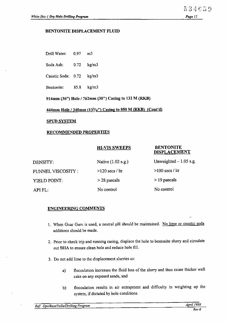
White Ibis-J Dry Hole Drilling Program
BENTONITE DISPLACEMENT FLUID
Drill Water: 0.97 m3
Soda Ash: 0.72 kg/m3
Caustic Soda: 0.72 kg/m3
53'lCJGPage 12
Bentonite: 85.8 kg/m3
914mm (36") Hole 1762mm (30") Casing to 132 M (RKB)
444mm Hole 1340mm 033/8") Casing to 850 M (RKB) (Cont'd)
SPUD SYSTEM
RECOMMENDEDPROPERTffiS
HI-VIS SWEEPS BENTONITEDISPLACEMENT
DENSITY: Native (1.02 s.g.) Unweighted - 1.05 s.g.
FUNNEL VISCOSITY: >120 sees / Itr >100 secs IItr
YIELD P01NT: > 28 pascals > 19 pascals
APIFL: No control No control
ENGINEERING COMMENTS
I. When Guar Gum is used, a neutral pH should be maintained. No lime or caustic soda
additions should be made.
2. Prior to check trip and running casing, displace the hole to bentonite slurry and circulate
out BHA to ensure clean hole and reduce hole fill.
3. Do not add lime to the displacement slurries as:
a) flocculation increases the fluid loss of the slurry and thus cause thicker wall
cake on any exposed sands, and
b) flocculation results in air entrapment and difficulty in weighting up the
system, if dictated by hole conditions.
Ref Ops/BasslYolla/Dril/ing Program April J998
Rev 0

White Ibis-J Dry Hole Drilling Program
Drilling Fluid Procedure (Cont'd)
311 mm (12 '/..") HOLE 1 244mm (95/S") CASING TO 2,150 M ffiKB)
KCIIlDBOND PHPA POLYMER SYSTEM
Reactive and dispersible shale fonnations will be encountered in this interval.
53 11CGOPage /3
A KCI 1 IDBOND polymer is recommended to provide the level of inhibition required forsuccessful drilling.
Based on offset well experience, a level of 5% w/w ofpotassium chloride is recommended.
Nevertheless, cuttings must be carefully examined for any signs of hydration (lack of
inhibition) and appropriate corrective action initiated, if necessary.
The inhibitive effect of the potassium ion will be supplemented by additions of IDBOND,
PHPA polymer. This polymer encapsulates drilled cuttings, minimising their dispersion
and improving solids control efficiency. Dilution rates will therefore be lowered.
IDBOND also "plasters" off the wellbore, minimising filtrate invasion and enhancing
wellbore stability. Additions will be stopped prior to reaching the prognosed depth of the
reservOIr.
Like all non-dispersed water-based fluids, this system is sensitive to the levels of entrained
drilled solids. These must be carefully monitored and controlled at a maximum of 6% vlv
to control the rheology, particularly the gel strengths in the desired ranges.
Fluid yield point is to be 18-22 kg/100ft2 in this section to ensure good hole cleaning at the
anticipated high rates ofpenetration.
Of critical importance to the successful completion of this interval is mud weight.
Mud density should be controlled initially at 1.1 s.g., and raised as hole conditions dictate.
Mud weights up to 1.20 s.g. have typically been used by section TD.
Lost circulation has been observed to siltstones and sandstones below the 340mm (133/8")
casing shoe. Any increase in mud weight should be made only in response to hole
conditions.
Differential sticking in the reservoir is always a potential occurrence, though it has not been
encountered on offset wells.
The fluid loss must be strictly controlled below 6mls to minimise the possibility of
differential sticking. Filter cake thickness must be carefully monitored and maintained as
thin and tough as possible.
No high temperature products or high temperature stabilisers will be required.
Ref Ops/BassIYalia/Drilling Program April /998
Rev 0
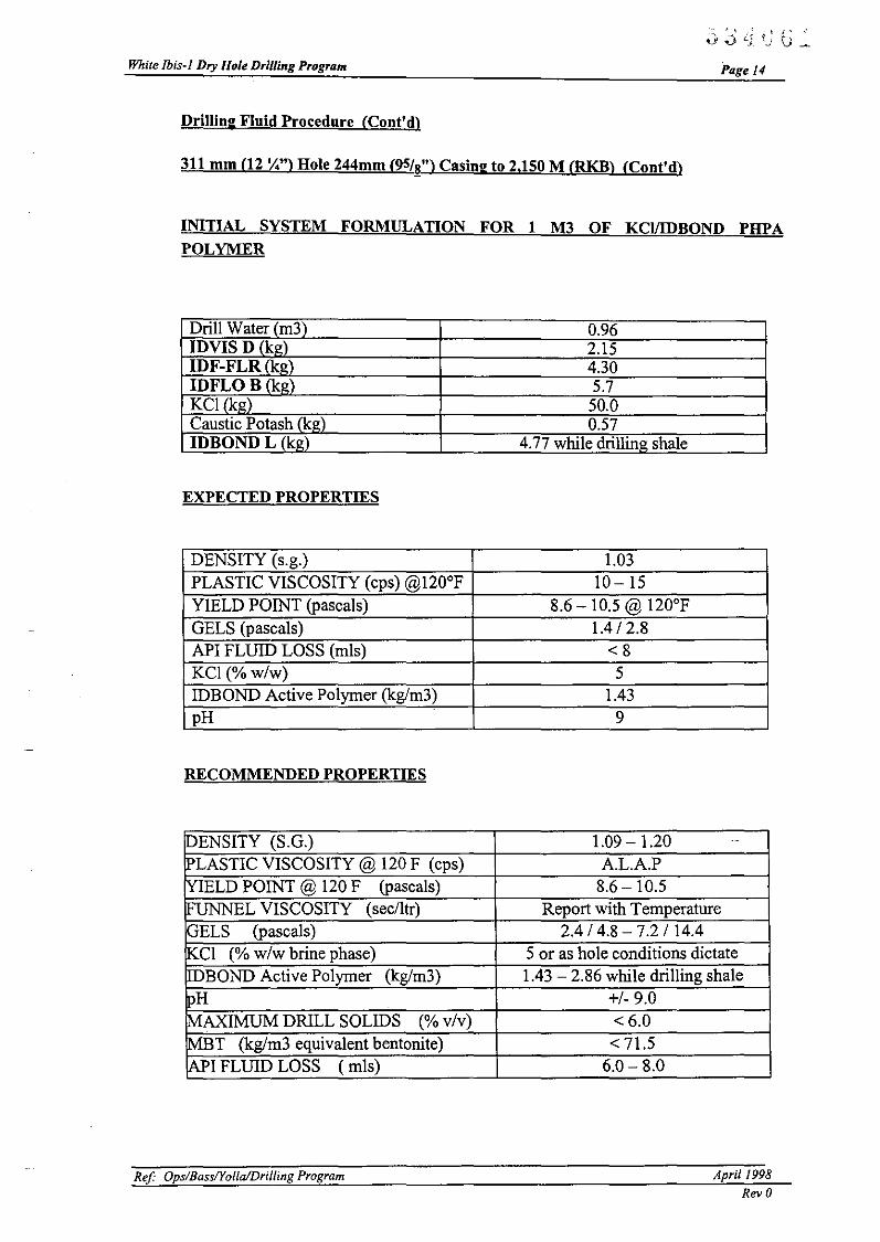
White lbis-l Dry Hole Drilling Program
Drilling Fluid Procedure (Cont'd)
311 mm (12 ';..") Hole 244mm (95/8") Casing to 2,150 M (RKB) (Cont'd)
Page 14
INITIAL SYSTEM FORMULATION FOR 1 M3 OF KCIIIDBOND PHPAPOLYMER
Drill Water (m3)IDYlS D (kg)IDF-FLR (kg)IDFLO B (kg)KCI (kg)Caustic Potash (kg)IDBOND L (kg)
EXPECTED PROPERTIES
0.962.154.305.7
50.00.57
4.77 while drilling shale
DENSITY (s.g.) 1.03PLASTIC VISCOSITY (cps)@120°F 10-15YIELD POINT (pascals) 8.6 - 10.5 @ 120°FGELS (pascals) 1.4/2.8API FLUID LOSS (mls) <8KCI(%w/w) 5IDBOND Active Polymer (kg/m3) 1.43pH 9
RECOMMENDED PROPERTIES
pENSITY (S.G.) 1.09 - 1.20 _.
IPLASTIC VISCOSITY @ 120 F (cps) A.L.A.PIYIELD POINT @ 120 F (pascals) 8.6 - 10.5IFUNNEL VISCOSITY (sec/ltr) Report with TemperatureGELS (pascals) 2.4 / 4.8 - 7.2 /14.4KCI (% w/w brine phase) 5 or as hole conditions dictateDBOND Active Polymer (kg/m3) 1.43 - 2.86 while drilling shale
pH +/- 9.0MAXIMUM DRILL SOLIDS (% v/v) < 6.0MET (kg/m3 equivalent bentonite) <71.5~I FLUID LOSS ( mls) 6.0- 8.0
Ref Ops/BassIYolla/Drilling Program April 1998
Rev 0

White Ibis-J Dry Hole DrilUng Program
Drilling Fluid Procedure (Cont'd)
311 mm (12 '/4") HOLE SECTION
SPECIFIC ENGINEERING COMMENTS
1. DRILLING OUT SHOE
Page 15
Drill out the shoe and clean out the rat hole using seawater and viscous pills (using fluid
displaced from inside 340mm (133/8") casing). This will eliminate cement contamination of
the new polymer fluid and subsequent conditioning.
2. RESERVE VOLUME
The properties of all water-based muds can deteriorate much more rapidly than oil-based
muds due to their greater degree of interaction with formation drilled.
Frequent checking of the active system is essential. Premix volume of approximately 25
30% of the active volume must be available at all times in the event of major whole mud
dilution being required to control mud properties.
3. STOCK LEVELS
Dilution rates of up to 0.3 m3/M can be expected.
It remains essential that sufficient stocks of materials are available to cope with these
estimated dilution rates.
Suggested minimum stock levels to start this section are:
120 Sx240 Sx320 Sx
80 Sx80 Dm
250 MT24 Dm32 Dm16 Dm
192 Dm
IDYlS D polymerIDF-FLRIDFLOBIDF-FLRXLCaustic PotashBariteIDCIDELDEFOAMERDRILLING DETERGENTIDBOND
4. MUD WEIGHT
Initial mud weight is to be controlled at 1.1 s.g. - use of a lower density will probably result
in tight hole and even caving formation. Increases in mud weight are to be made ONLY in
response to tight hole conditions and/or caving formation due to the possibility of losses to
siltstone and sandstone formation below the 340mm (133/8") casing shoe.
Ref' Ops/BasslYolla/Drilling Program April 1998Rev 0

While Ibis-I Dry Hole Drilling Program Page 16
Losses and differential sticking in the reservoir are potential occurrences. Increases in mud
density are to be made ONLY in response to alleviate tight hole and/or caving formation orcontrol formation pressures and are to be made incrementally.
STRICT CONTROL IS REQUIRED. Only use a tru-weight (pressurised) mud balance..
5. INHIBITION LEVELAn ion selective electrode is to be used to determine the potassium ion level in the fluid.
On no account is the chloride level to be used as an indication of the potassium ion
concentration. The potassium concentration should be maintained either by direct addition
ofKCI powder to the active system or by suitably dosed premixes.
Should bit balling occur, inhibition levels should be reviewed. As a temporary measure,
addition of 1.0% v/v Drilling Detergent (I x 200 It dm per 20 m3 of mud) is recommended.
The inhibition of the system can be increased by incremental increases of potassium
chloride of 5 ppb.
AlI premixes are to be formulated with 4.77 kg/m3 IDBOND Liquid PHPA.
AlI maintenance additions of PHPA are to be made using IDBOND liquid PHPA
DIRECTLY to the active system. Use of the liquid product will provide for easier and more
effective addition while drilling.
An excess ofIDBOND of 1.43 - 2.86 kg/m3 is to be maintained. As a guideline, 2 drums
of IDBOND liquid PHPA will have to be added directly to the active for every 30 M of
hole drilled.
6. ill!
The pH is to be maintained at ca.9 to reduce corrosion but also minimise dispersion of
claystone.
Caustic potash is to be used for pH control rather than caustic soda which will provide
additional potassium ions and so aid inhibition.
7. FLUID LOSS
API filtrate is to be controlled between 6 - 8mls down to the prognosed depth of the top of
the reservoir.
Prior to drilling ahead through the reservoir, the API fluid loss must be lowered to below 6
mls to minimise the potential for differential sticking. This fluid loss must be maintained at
this level to TO. Should any increases in mud density have to be made, say 0.05 s.g. and
more, the fluid loss should be lowered further to caAmls.
Ref Ops/BassIYollaiDrilling Program April 1998
Rev 0

White Ibis-J Dry Hole Drilling Program
8. SOLIDS CONTROL EOUIPMENT
Page J7
Once the polymers have been sheared, the finest possible screens must be utilised on the
shale shakers.
Mud cleaner / desilter is to be run only in the event of problems with shaker screen
blinding.
9. BIOCIDE TREATMENT
Test slides are to be used on a daily basis to determine the level of bacteria present in the
mud. Close monitoring of filtrate loss and pH in conjunction with the results of "bug" tests
will determine whether treatment with biocide, IDCIDE L, is necessary. The use of biocide
treated starch, IDFLO B should minimise, if not eliminate the need for any biocide
treatment.
10. CARBONATE CONTAMINATIONCarbon dioxide contamination has been encountered on offset wells below 1700 M. A
Garret Gas Train will be used to monitor the drilling fluid for the presence of carbonates.
Treatment with lime or calcium chloride may be required, depending on the pH of the
drilling fluid.
Ref Ops/BassIYalia/Drilling Program April J998
Rev a

APPENDIXC
CEMENTING PROGRAM
53LIC6~

White lbis-l Dry Hole Drilling Program
Cementing program 762 mm (30") Conductor
Objective:
534G6GPage 19
Required TOC is at seabed. Case off the unconsolidated formation by setting the 30" (762 mm)
casing 60m below the seabed at 151m RKB. A tail pipe below the casing running tool will be used
to ensure cement to surface with minimum excess slurry pumped.
Well considerations:
No hydrocarbons are expected and formation pressures are hydrostatic at 1.02 sg equivalent.
BRST/BRCT=27/27 degrees Celsius
The maximum expected ECD for this job is 1.3 sg (referenced to sealevel) at the 30" (762 mm)
shoe. Based on this value losses are unlikely to occur. If total losses do seem to occur, it should be
attempted to reduce the pumprate. If total losses occur, a topfin job may be attempted through
spaghetti tubing.
Centralisation:
The wen is planned vertical and for this short section no centralisers should be required. Also
indications from the attached simulations show that even at minimum casing stand-off the slurry
will still efficiently displace any fluid in front of it.
Slurry considerations:
A single 1.90 sg Class 'G' slurry is proposed with the fonowing composition:
Class 'G' cementSeawaterD047 AntifoamCaCI2 AcceleratorDensityYieldThickening time24 hr. compo Strength
Slurry volume:
sk of 94 Ibs (42.6 kg)5.16 gal/sk (458 Jtr/mT)0.01 gal/sk (0.9ltr/mT)2% BWOC15.8 ppg (1.90 sg)1.16 cuftlsk (0.78 m3/mT)+/-2 hrs+/-3000 psi
The estimated slurry volume is based on 30" (762 rom) casing in 36" (914 rom) open hole plus 150
% excess.
Ref Ops/BasslYo/la/Drilling Program April 1998
Rev 0
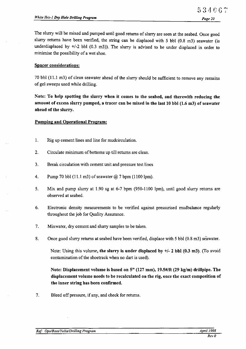
White Ibis-J Dry Hole Drilling Program Page 20
The slurry will be mixed and pumped until good returns of slurry are seen at the seabed. Once good
slurry returns have been verified, the string can be displaced with 5 bbl (0.8 m3) seawater (is
underdisplaced by +/-2 bbl (OJ m3)). The slurry is advised to be under displaced in order tominimise the possibility of a wet shoe.
Spacer considerations:
70 bbl (11.1 m3) of clean seawater ahead of the slurry should be sufficient to remove any remainsof gel sweeps used while drilling.
Note: To help spotting the slurry when it comes to the seabed, and therewith reducing the
amount of excess slurry pumped, a tracer can be mixed in the last 10 bbl (1.6 m3) of seawaterahead of the slurry.
Pumping and Operational Program:
I. Rig up cement lines and line for mudcirculation.
2. Circulate minimum ofbottoms up till returns are clean.
3. Break circulation with cement unit and pressure test lines
4. Pump 70 bbl (11.1 m3) of seawater @ 7 bpm (1100 Ipm).
5. Mix and pump slurry at 1.90 sg at 6-7 bpm (950-1100 Ipm), until good slurry returns are
observed at seabed.
6. Electronic density measurements to be verified against pressurised mudbalance regularly
throughout the job for Quality Assurance.
7. Mixwater, dry cement and slurry samples to be taken.
8. Once good slurry returns at seabed have been verified, displace with 5 bbl (0.8 m3) seawater.
Note: Using this volume, the slurry is under displaced by +/. 2 bbl (0.3 m3). (To avoid
contamination of the shoetrack when no dart is used).
Note: Displacement volume is based on 5" (127 mm), 19.5#/ft (29 kg/m) drillpipe. The
displacement volume needs to be recalculated on the rig, once the exact composition of
the inner string has been confirmed.
7. Bleed offpressure, if any, and check for returns.
Ref' Ops/Bass/YollaJDriiiing Program Aprii 1998
Rev 0
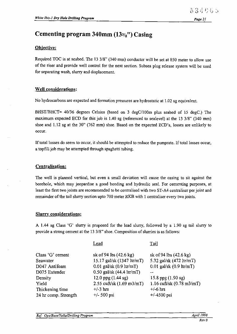
White Ibis-} Dry Hole Drilling Program
Cementing program 340mm (133/8") Casing
Objective:
Page2!
Required TOC is at seabed. The 13 3/8" (340 mm) conductor will be set at 850 meter to allow use
of the riser and provide well control for the next section. Subsea plug release system will be usedfor separating wash, slurry and displacement.
Well considerations:
No hydrocarbons are expected and formation pressures are hydrostatic at 1.02 sg equivalent.
BHST/BHCT= 40/36 degrees Celsius (based on 3 degCIIOOm plus seabed of 15 degC.) The
maximum expected ECD for this job is lAO sg (referenced to sealevel) at the 13 3/8" (340 mm)
shoe and 1.12 sg at the 30" (762 mm) shoe. Based on the expected ECD's, losses are unlikely to
occur.
If total losses do seem to occur, it should be attempted to reduce the pumprate. If total losses occur,
a topfill job may be attempted through spaghetti tubing.
Centralisation:
The well is planned vertical, but even a small deviation will cause the casing to sit against the
borehole, which may jeopardise a good bonding and hydraulic seal. For cementing purposes, at
least the first two joints are recommended to be centralised with two ST-A4 centraliser per joint and
remainder of the tail slurry section upto 700 meter RKB with I centraliser every two joints.
Slurry considerations:
A 1.44 sg Class 'G' slurry is proposed for the lead slurry, followed by a 1.90 sg tail slurry to
provide a strong cement at the 13 3/8" shoe. Composition of slurries is as follows:
Class 'G' cementSeawaterD047 AntifoamD075 ExtenderDensityYieldThickening time24 hr camp. Strength
Ref OpslBassIYo/la/Dril/ing Program
sk of941bs (42.6 kg)15.l7 gal/sk (1347Itr/mT)0.01 gal/sk (0.9Itr/mT)0.50 gal/sk (44.4 Itr/mT)12.0 ppg (1.44 sg)2.55 cuft/sk (1.69 m3/mT)+1-3 hrs+1- 500 psi
sk of941bs (42.6 kg)5.32 gal/sk (4721tr/mT)0.01 gal/sk (0.9 Itr/mT)
15.8 ppg (1.90 sg)1.16 cuft/sk (0.78 m3/mT)+1-6 hrs+1-4500 psi
April!998Rev 0

White Ibis-J Dry Hole Drilling Program
Slurry volume:
Page 22
The estimated slurry volume is based on 13 3/8" (340 rom) casing in 17 112" (445 mm) open hole
plus 100% excess. The excess may be increased depending on hole conditions. The volume based
on 100% works out at 690 bbl (100 m3) of slurry: 122 bbl (19.5 m3) of tail slurry to cover 150meter annular length and 568 bbl (80.5 m3) oflead slurry to take TOC to seabed.
Spacer considerations:
70 bbl (11.1 m3) of clean seawater ahead of the slurry should be sufficient to remove any remainsof gel sweeps used while drilling.
Note: To help spotting the slurry when it comes to the seahed, and therewith reducing the
amount of excess slurry pumped, a tracer can he mixed in the last 10 bhl (1.6 m3) of seawaterahead of the slurry.
Pumping and Operational Program:
1. Rig up subsea cement head, cement lines and line for mudcirculation.
2. Circulate minimum ofbottoms up till returns are clean.
3. Break circulation with cement unit and pressure test lines
4. Pump 70 bbl (11.1 m3) of seawater @ 7 bpm (I 100 Ipm).
5. Release ball for bottom plug
6. Mix and pump 568 bbl (80.5 m3) of 1.44 sg lead slurry at 7-8 bpm (1100-1270
Ipm)
7. Mix and pump a minimum 125 bbl (19.9 m3) of 1.90 sg tail slurry at 6-7 bpm (950
1100Ipm).
8. Electronic density measurements to be verified against pressurised mudbalance
regularly throughout the job for Quality Assurance.
9. Mixwater, dry cement and slurry samples to be taken.
10. Release dart for top plug
II. Displace with mud at minimum 15 bpm (2385 Ipm). The first 10 bbl (1.6 m3)
should be pumped at reduced rate in order to get a positive pressure indication
when the dart lauches the top plug.
ReF Ops/Bass/Yolla/Drilling Program April 1998
Rev 0
White lbis-/ Dry Hole Drilling Program Page 23
12. Slow down to 5 bpm (795 lpm) for the last 10 bbl (1.6 m3) in order to have a
controlled bumping of the plug.
13. Bump plug and pressure test casing as required
14. Bleed off pressure and check for returns.
Ref Ops/BassIYalia/Drilling Program April/99B
Rev 0

White Ibis-J Dry Hole Drilling Program
Cementing program 244mm (95/8") Casing
Objective:
534C71Page 24
Required TOC is at 1400 meter (+/-200 meter above shallowest expected hydrocarbon bearing zone
at EVCM). The 244mm (9 5/8") production casing will be set at 2150 meter. 9 5/8" casing will be
run to surface and full bore plugs will be used for separating spacer, slurry and displacement.
Well considerations:
Hydrocarbons are expected and formation pressures are at this point unknown but not expected to
be highly over pressured. BHSTIBHCT= 80/ degrees Celsius (based on 3 degC/lOOm plus seabed
of IS degC.). Top of zone of interest is 1400 meter.
The maximum expected ECD (based on static cement column) for this job is 1.44 sg (referenced to
rigfloor) at the 9 5/8" (244 mm) shoe.
If total losses occur during the job, it should be attempted to reduce the pumprate. As V-tubing will
occur during this job, a temporary reduction of returns should not be confused with losses.
Centralisation:
The well is planned vertical, but even a small deviation will cause the casing to sit against the
borehole, which will jeopardise a good bonding and hydraulic seal. For a good seal and bonding
across the reservoir section, the first two joints are recommended to be centralised with two ST-A3
centralisers per joint, and a further 850 meter (upto 100 meter above zone of interest) should be
centralised with one centraliser per joint.
If prevention of annular flows and/or pressures is a concern in this area, ST-A3 centralisers should
be run at I per 2 joints upto required TOC at 1400 meter.
Ref Ops/BassIYalia/Drilling Program April 1998Rev 0

White Ibis-! Dry Hole DrUling Program
Slurry considerations:
Page 25
Because the operator is not expecting the bottom hole static temperature to be above 90 degreesCelsius, the slurry designs are without silica. No lead slurry is required. A 1.90 sg Class 'G' filler
slurry is proposed for the tail slurry to provide a strong cement across the zone of interest. Theslurry compositions are as follows:
Class 'G' cementSeawaterDrillwaterD047 AntifoamD075 ExtenderD300FLACD145 DispersantDII0 RetarderDensityYieldThickening time24 hr compo Strength
Slurry volume:
Leadsk of 94 Ibs (42.6 kg)9.75 gallsk (865 Itr/mT)
0.01 gallsk (0.9ltr/mT)0.35 gallsk (31.1ltr/mT)
0.25 gallsk (22.2 ltr/mT)13.2 ppg (1.58 sg)1.86 cuft/sk (1.24 m3/mT)+1- 5.5 hrs+1- 1000 psi
Tailsk of941bs (42.6 kg)
3.99 gallsk (354 Itr/mT)0.03 gallsk (2.7 Itr/mT)
0.90 gallsk (79.9ltr/mT)0.25 gallsk (22.2 ltr/mT)0.03 gallsk (2.7 ltr/mT)15.8 ppg (1.90 sg)1.16 cuft/sk (0.78 m3/mT)+1- 4 hrs+1- 4200 psi
The slurry volume should be based on caliper log plus 10% excess. For planning purposes thevolume is based on 9 5/8" (244 mm) casing in 12 1/4" (311 mm) open hole plus 50% excess. For
TOC at 1400 meter, the total required slurry volume is 205 bbl (33 m3) of slurry to take TOC to1400 meter.
Spacer considerations:
To thin and remove mud from the annulus, it is advised to pump 70 bbl (11.1 m3) of turbulent
Chemical wash to thin the mud and breakdown the filtercake (if formation pressures allow, morewash may be pumped). The chemical wash will be followed by 60 bbl (9.5 m3) of weightedMudpush spacer to remove the filtercake.
Pumping and Operational Program:
I. Make up cement head to casing.
2. Rig up cement lines and line for mudcirculation.
3. Circulate minimum ofbottoms up till returns are clean.
4. Break circulation with cement unit and pressure test lines
5. Pump 70 bbl (11.1 m3) of Chemical wash@ 7-8 bpm (1100-1270 Ipm).
Ref OpslBasslYolla/Drilling Program April!998
Rev 0

White lbis-l Dry Hole Drilling Program
6. Pump 60 bbl (9.5 m3) of Mudpush spacer@ 7-8 bpm (l100-1270Ipm)
7. Release bottom plug
Page 26
8. Mix and pump a minimum 205 bbl (33 m3) of 1.90 sg tail slurry at 6-7 bpm (950
11001pm)
9. Electronic density measurements to be verified against pressurised mudbalance
regularly throughout the job for Quality Assurance.
10. Mixwater, dry cement and slurry samples of each stage to be taken.
II. Release top plug
12. Displace with mud at IS bpm (2385 Ipm). Slow down to 5 bpm (795 Ipm) for the
last 10 bbl (1.6 m3) in order to have a controlled bumping of the plug.
13. Bump plug and pressure test casing as required
14. Bleed offpressure and check for returns.
Ref Ops/BossIYolla/Drilling Program April 1998Rev 0

APPENDIXD
CASING DESIGN

White Ibis-J Dry Hole Drilling Program
Casing Design Summary
API minimum Design Safety Factors:-
BURST 1.1COLLAPSE 1.05TENSION 1.6
Casing Size OD (mm) 762 340 244
Hole Size (mm) 914 444 311
Shoe Depth (m RKB ) 125 850 2150
Casing Grade GRB L80 L-80
Casing Weight (kg/m) 462 101 79.6
Casing Connection ST-2 NewVAM New VAM IVAMACE
Casing Size ID (mm) 711 315 216.8
Casing Drift (mm) 311.4 216 - special
drift
Minimum Internal Yield (kPa) 33987 54669
Collapse Resistance (kPa) 15649 45638
Tensile Strength (1000 kg) 3431 2743
Burst Design Factor 2.08 2.66
Collapse Design Factor 1.60 2.37
Tension Design Factor 6.38 2.56
Pressure Test (kPa) 5500 28000
Comments Conductor Surface Production
Page 28
Ref OpsiBassIYollaiDri/ling Program AprilJ99828Rev 0

WHITE ISIS - 1CASING PROGRAMME (R.K.S.)
Water Depth 79.4m
JTorquay Group @ seabed
Angahook Formation - not expected
Demons Bluff Formation @ 1440 m
Eastern View Coal Measures @ 1594 m
•• Formation tops based on Yolla-1
'iii Scm
L 762mm Casing462kg/m GR B RL4@132m
340mm Casing101kg/m LBO VAM@B50m
244mm Casing
79kg/m LBO, VAM ACE@2150m
./

·White Ibis-1
WHITE 181S-1 Casing & Running Strings
30- 13318" 9518-
_ Wlhead housing -
5" G or$135 drill pipe
-PGB
IRiiiTooh18314" W/head
_ W/head housing-
5" G or 5135 drill pipe
~PGBIRiii T0011
16314" Wlhead
-5" G or 5135 drill pipe
'Rig Tool I_ Wlhead housing ~
~ ~PGB
I--
I-----j30" GR B RL4 W/Head Extension
1-__-130" GR B RL4 intermediate joint
Crossover
L.... r- 20" x 13 318" swedge
I-- 13 3/8" aTC Pin
13 318" aTe Box
13318: NewVAMPin
1-__~9 518" New VAM Pup joint
9518" New VAM Box
I-__~ 95/8" VAM ACE Pin
95/8" VAM ACE Casing
9518" VAM ACE Casing
1-__--j30" GR B RL4 intermediate joint
t----- 133/S" NewVAM casing 9 51S" VAM ACE Casing
9518" VAM ACE Casing
1-__-130" GR 8 RL4 intermediate joint
_ 133fS" NewVAM casing
r--- 13318" Float Collar 1-__----j9 516" Float Collar
Shoe track _ 13318" New VAM casing Shoe Track 1-__-19518" VAM ACE Casing
L __....J30· GR B RL4 shoe joint Shoe track _ 13318" New VAM casing
L....- 133(8" Float Shoe
Shoe Track 1-__-19518" VAM ACE Casing
L-__-l9 518" Float Shoe
Page 15cm

BHA LENGTH
4 MAA.S.P.:
CURRENT DEPTH ·lVD:
5 MAX SHOE PRESSURE
1.20 s.g.
311 mm
127 mm203 mm
1.60 s.g.
123.3 m
850.00 m
2150 m
2.7 kPa/m
1176.7 m
123.3 m
5.4 m374.5 m3
3334.0 kPa
13336.1 kPa
15297.3 kPa
25299.4 kPa
368.3 m
23.3 m3
12.3 m3
5.4 m3
232.5 m
It
It
It
It
It
in
in
in
ppg
ppg
psi/It I
8.0
0.12
7054
5.00
404.5
13.34
12.25
10.00
404.55
2788.85
33.83 Bbls468.61 Bbls
483.61 psi
1.934.45 psi
2.218.93 psi
3.669.77 psi
1,208.34 It
146.7 Bbls
77.31 Bbls
33.83 Bbls
762.82 It
3.860.75
BHA IN OPEN HOLE
DRILL PIPE IN OPEN HOLE
INFLUX GRADIENT:
LAST CASING I LINER SET AT • lVD:
CURRENT MUD WT. =
3 ANNULAR VOLUME OF O.H.Due to BHADue to D.P.
DRILL PIPE 0.0.BHA ( COLLARS) 0.0.
L.O.T.· E.M.W. =
CURRENT HOLE SIZE =
7 ESTiMATED PORE PRESSUREAssumes Mud weight only just overbalance
8 HEIGHT OF INFLUX @ SHOE
9 INFLUX VOLUME @ SHOE
6 OH PRESSURE DUE TO MUD
2
1
12 HEIGHT OF INFLUX@ TD
10 INFLUX VOLUME @TD
11 VOLUME AROUND COLLARS
Page 2

ISURFACE CASING DESIGN - 339.725 mm
CSG DES Surf
White Ibis - I
Selected casing specifications J
Proposed Casing Reference Number:Outside Diameter: Cod 13.375 in 340 nunWeight: Wt 68.0 Ib/ft 101.2 kg/mGI1lde : L-80Minimum Internal Yield pressure: Miy 4,930 psi 33,987 kPaCollapse Resistance: Coli 2.270 psi 15,649 kPaTensile Strength : Ten 1,556 k.lbs 3,431 k.kgInternal Diameter: Cid 12.415 in 315.3 nunCasing Connection: NewVAM
Design Safety Factor SummaryBurst Collapse Tensile
Required OSF 1.10 1.05 1.60Actual DSF 2.08 1.60 6.38Meets Design Requirements? Yes Yes Yes
Design Considerations IDepth ofcasing shoe Osh 2.789 ft 850 mMud density behind casing Rmb 10.00 ppg 1.20 sg
Top ofcement Otoe o ft OmCement slurry design : Oemlt I Oemlb I
Lead slurry CmI 12.6 ppg from 0 to 2;297 ftTail slurry Cmt 15.8 ppg from 2,297 to 2,789 ft
Oemtt ·1 Oemtb ·1Next Hole section TO Otd 7,054 ft 2,150 m
Max pore pressure in next hole section Rf 8.7 ppg 1.042 sgMax mud weight in next hole section Rm 10.0 ppg 1.200sgLeak-offat shoe Rsh 13.3 ppg 1.60 sg
Gas gradient Rg 0.12 psilft 2.71 kPaimWater depth Ow 197 ft 60 mRotary table elevation Orte 41 ft 12.5 mSeawater gradient Rsw 0.45 psilft 10.18 kPaimCasing Pressure tested to : Cpt 800 psi 5.515 kPaim
Burst Design I
Intemalloading condition:
Extemalloading condition:
Gas column to surface with influx at TD.
Water Depth
Expected Pore Pressure: 10.0 ppg 1.20 sg from offset data I
Burst at Casing Head: (Otd*R!"0.052)-((Old-Ow-Orte)*Rg)
Burst design factor:
Pbst
Miy I Pbst
I 2,369 psi
2.08
Page 3
16,329 kPa
,

CSG DES Surf
Collapse Design I
Intemal10ading condition: Drilling at section TO and losses result in mud level dropping to 50%orhole depth
Extemal10ading condition: Hydrostatic pressure exerted by the column ofmud behind casing
Mud weight: I 10.0 ppg 1.20 sg IMud level = I 3,527 ft 1 1,075 m
Dmcp Maximum collapse pressure is at I 2,789 ft 1 850 m
Max collapse pressure: {(Dmep - (Dw + Drte)) x Rmb x 0.052} + (Dw x Rsw)
Peolt =1 1,416 psi I 9,760 kPa
Collapse design factor: Coli / Peoll = 1 1.60 I
Collapse Cementing Check I
Intemal10ading condition: Evacuated to seawater
Extemalloading condition: Hydrostatic pressure due to a cement column 10% above programmedweight
Collapse pressure at shoe: {(Demtb - Demtt) x (Cm! x 110% x 0.052) + (Dw x Rsw)
+ {(Deml! - Dw - Drte) x Rmb x 0.052}
+ (Demlb - Demit) x (Cml x 110% x 0.052)}
- «Dsh - (Dw + Drte)) x Rsw}
Pealc =I 917 psi I 6,322 kPa
Collapse design factor: Coli / Peole = I 2,48 IWorst case collapse design factor: = I 1.60 I
53,lG80
Tension Design
Loading condition:
Mudweight:
Buoyancy Factor BF :
Tension at mudline :due to weight:
due to press test:
Tension design factor:
I
Weight ofcasing string in mud plus pressure test assuming no cementaround outside ofcasing
----:1.:.,:O.O'---"pp"'g'--_1 1,-_..;.1.,;;,;20;,.;s",-g_.....J
0.847
Wt x (Dsh-Dw-Drte) =1 147,012 lbs 66,672 kg+
Cpt x «Cid/2)"2 x PI) =1 96,844 Ibs 43,920 kg
Tmax =1 243,856 Ibs 110,592 kg
Ten I Tmax I 6.38
Page 4

IPRODUCTION CASING DESIGN - 9.62510
eSG DES Prod
White Ibis· 1
Selected casing specifications IProposed Casing Reference Number:Outside Diameter: Cod 9.625 in 244.5 romWeight: Wt 53.5 lb/ft 79.6 kg/mGrade: L·80Minimum Internal Yield pressure : Miy 7,930 psi 54,669 kPaCollapse Resistance: Coli 6,620 psi 45,638 kPaTensile Strength: Ten 1,244 klbs 2,743 kkgInternal Diameter: Cid 8.535 in 216.8 mmCasing Connection: NewVAM/VAMACE
Design Safety Factor Summary
Burst Collapse Tensile
Required DSF 1.10 1.05 1.60Actual DSF 2.66 2.37 2.56
Meets Design Requirements? Yes Yes Yes
Design Considerations IHole section TO Dtd 7,054 ft 2,150.0 m
Depth of casing shoe Dsh 7,054 ft 2,150.0 mMud density behind casing Rmb 10.0 ppg 1.20 s.g
Max pore pressure Rf 8.7 ppg 1.042 s.g
Max mud weight Rm 10.0 ppg 1.20 s.g
Packer depth Dpk 5,578 ft 1,700.0 m
Testing kill fluid density Rtkf 10.8 ppg 1.30 s.g
Pore pressure at packer depth Rfte 8.7 ppg 1.042 s.g
Top of cement Dtoc 4,593 ft 1,400.0 m
Cement slurry design : Demit I Dcmlb ILead stuny Cml 12.8 ppg from 1,400 to 1,400 ft
Tail slurry Cmt 15.8 ppg from 1,400 to 7,054 ft
Dcmtt I Dcmtb IGas gradient Rg 0.12 psi/ft 2.7 kPaim
Water depth Dw 197 ft 60.0 m
Rotary table elevation Drte 41 ft 12.5 m
Seawater gradient Rw 0.45 psi/ft 10.2 kPaim
Casing Pressure tested to : Cpt 3,100 psi 21,371.4 kPa
Burst Design J
Internal loading condition:
External loading condition:
Burst at Casing Head:
A tubing leak at surface while testing, applying reservoir pressure on top ofa colunm ofkill weight fluidPore pressure at packer setting depth
((Dtd-Dw-Drte) x Rfx 0.052) - (Dtd x Rg)
Burst design factor:
Pbst
Miy I Pbst
2,233 psi
_.....;3;;;.5;;;5:.........J1 (shoe)
Burst at Packer: «(Dtd·Dw-Drte) x Rfx 0.052) - (Dtd x Rg) + (Dpk x Rtkf x 0.052) • (Dtoe x Rmb x 0.052)
Pbst 2,987 psi
Burst design factor;
Worst Case burst design factor:
Miy I Pbst
Page 5
2,66
2.66
(shoe)

eSG DES Prod
Collapse Design I
Intemalloading condition: Perforations plugged during testing and surface pressure bled to zero with
full column of gas inside tubingExternal loading condition: Hydrostatic pressure exerted by the column of mud behind casing
Max collapse pressure: «Osh-Ow-Orte) x Rmb x 0.052) + {Ow x Rsw) -(Old x Rg)(at shoe) Peoll = I 2,788 psi I
Collapse design factor: Coll / Peoll = I 2.37 I
Collapse Cementing Check I
Intemalloading condition: Hydrostatic pressure exerted by the column of water
Extemal10ading condition: Hydrostatic pressure due to a cement column 10% above programmed
weight
Collapse pressure at shoe: {Oemlt x Rmb x 0.052}+{(Demlb - Oemlt) x (Cmt x 110% x 0.052)}+ {(Demlb - DemIt) x (Cml x 110% x 0.052)} - (Osh x Rw)
Pecic =1 2,664 psi I.
Collapse design factor: Coli / Pealc = I 2.49 IWorst case collapse design factor: = I 2.37 I
Tension Design
Loading condition:
Mud weight:
Buoyancy Factor BF :
Tension at mudline :due to weight:
I
Weight ofcasing string in mud plus pressure test assuming no cement
around outside of casing
10.0 ppg
0.85
WI x (Osh-Ow-Drte) x BF= I 309,056 Ibs
+due to press test;
Tension design fador :
Cpt x «Cidl2)A2 x PI)
Tmax
Ten I Tmax
= 1L-_L-17-'.7::;,,3.:;62:....;.lb;.:s _
= 1L.__4.;;g;.;;6;.:,4.;;18::..;,lb;;;s,-__
1_...:2:::;.5;;.,6-
Page 6

APPENDIXE
BLOWOUT PREVENTER PRESSURETESTING

White Ibis-J Dry Hole Drilling Program
BOP PRESSURE TESTING
534C81Page 41
Annular Preventer
Pipe Rams
Blind Ram
Choke / Kill Lines
Choke Manifold
All pressures in kPa.
1400/24100
1400/27600
1400/27600
1400/27600
1400/27600
BOP's, choke manifold and other well control equipment will be tested at the following
intervals, whichever comes first:
• after each new string of casing is run
• every 14 days regardless of the operation in progress
Before testing, ensure the casing annulus valve is opened to prevent casing collapse in the
event of a wellhead seal leak.
Casing will be pressure tested, prior to drilling out the casmg shoe, to the following
pressures:
340mm (133/8") Casing
244mm (95/8") Casing
5500 kPa
28000 kPa
The 340mm (13 3/8") casing pressure test is based on a surface pressure in excess of that
required to breakdown the 340mm (133/8") casing shoe with the casing fully evacuated to
gas.
The 244mm (95/8") casing pressure test is based on a surface pressure in excess of that
expected if the well is fully evacuated to gas at TD of the 216mm (8W') hole section with a
1.04 SG equivalent formation pressure.
Ref Ops/BassfYolla/Drilling Program April 1998Rev 0

APPENDIXF
WELLHEAD STACK-UP
DIAGRAMS

11 I ; 6 ,J I 2 I I
o
1<I
i!
1-,I
II,
i"ro
I,I,
I::C';'~''''.
I I I I I
II
"-
18-3/.' 10.Coo ?$ SC-lv.£!.LHEAQ S'.lC< 1.9. 30"x 20" (S·/IACC: 0'7CN)X 1.)-J/8· X ~;/8'
2
I ,]; LL' -f1 AlBa Ve!o:l Grav r
i F'lCPCS\l1 SS'4€ ,
I I
_..---
\
/
Scm
- -3 F1
- -. F""T
~-5 FT
~ -I F1
L. -6 FT
~ -2 FT
::: ~ R)'--OF""T--I_.- - - __ --Ji {;~~~ .
1 l I~ ~- ---f-'-;----- ,a-l/",~ YCI.H(.lo HOJS><C
24.r!' i ~~~.H~N~'t~~~ l0=01'\1 ~ i W/ cw H~t------------+++---------j,~'~;;::::: Ir_--:---;-7---- PAexCf'F' ASSE).lBlY.
125-1/2" ,J/2" ill :3 ~ I=:~ ill l8-l/", SG-l'"
I FFi (+\, l~' 0 ~ -L~.t......,,, GJC( B.<S< 1
1
~,'-+'I ~ -7 i~.: ~ .. t: rr1ii"1 ! .IlJ~1 II ~~,.•. I _ • • , I
CASI'C -'NG8. SG-;. , = ~I ~ __' ~ , , "---'la-l/" • 1J-l/a" ~
, A;J1j'-:- I11: ~[ll ~'!'~,,'ii?l'--- ='NC HAN<L', s.;...s,JO' oe.'-"E"l HeUSNC -------,---....-;:-: ,. " 0' II ~ 'a-l/4', g-~/a'
ffi r c('J'11 'I Ii ""lll"- I r'l0 ~ f&\m..O'URY c;.,eE eASE -:(0 )' I I,!' : I i,
.L...- -+I_I-__-----'-·..;::~::::::::..;.I , i 1'f-r--"l~I -1==== ·~Yk"- .1
lip, III i ""1'~1---20' ....T-2 ae.I I '! I ,.Jf'~Ii· I
JO' =Ne-__IIi LI
20' CASlNe----_,I.,..,-'i U0
II d i 20' ( 'J-l/a'
Il-l/S' <:.\SNe II :1 I CROSSO'.{il s·••~ •
---'7-;;-j11i I' III I
g-S/S'CASNO III I)I!Iii ,I rU'ifI. ,I .;" 'I 0,~. iIi
...J.;.--.'---'
o
c
e
C>
1-
1-
L
)
IIIIIIIIIII
•

APPENDIX G
REFERENCE DOCUMENTATION
53 tlC87
Reference Documentation
The following documents/information shall be available on the rig. Contact the Perth office
if any of this information is required:
• PremierOil Australasia, Drilling Operations and HSE Manual
• PremierOil Australasia, Bass Basin Emergency Response Manual
• PremierOil Australasia, Bass Basin Oil Spill Contingency Plan
• PremierOil Australasia, Bass Basin Enviromental Assessment
• PremierOil Australasia, Wellsite Geology Manual
• PremierOil Australasia, Bridging Document
• PremierOil Australasia, Well Control Procedures Manual
• Northern Explorer III Vessel Safety Case
• Northern Offshore Safety Management System
• Northern Offshore Emergency Response Manual
APPENDIX H
SUPPORT SERVICES
534csa
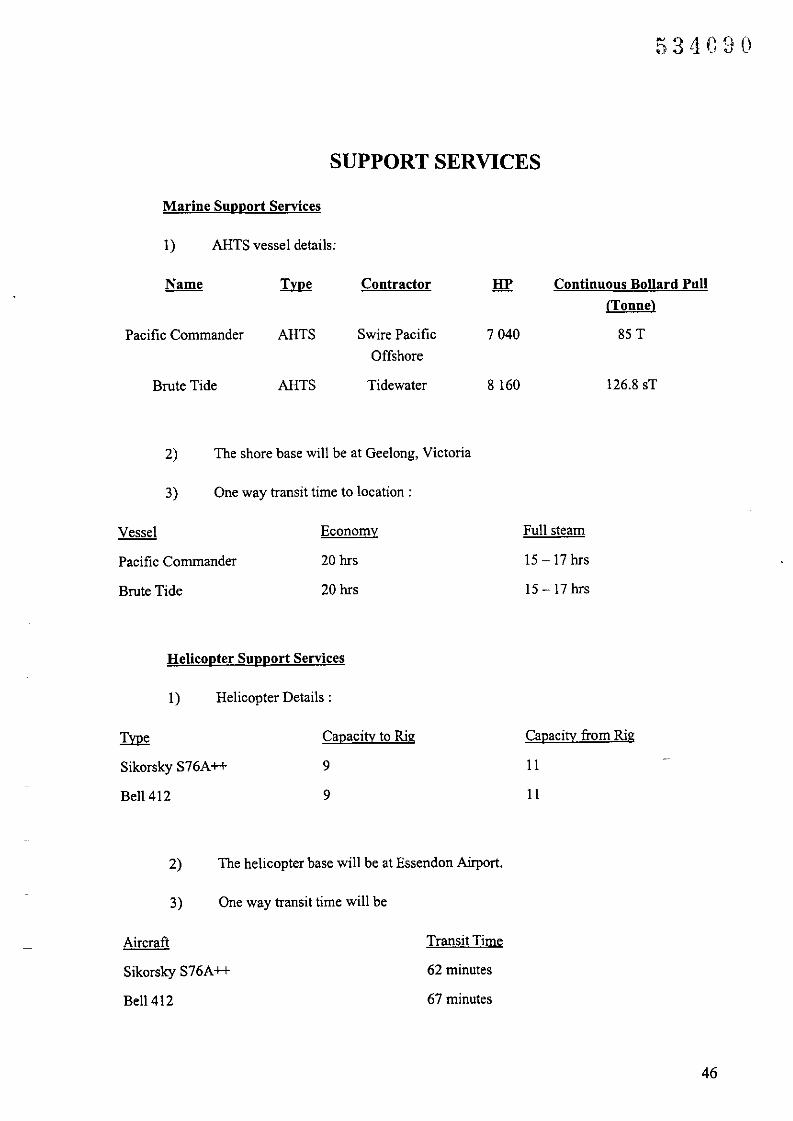
53 LIC30
SUPPORT SERVICES
Marine Snpport Services
I) ARTS vessel details:
Pacific Commander
Brute Tide
ARTS
ARTS
Contractor
Swire Pacific
Offshore
Tidewater
7040
8160
Continuous Bollard Pull(Tonne)
85 T
126.8 sT
2) The shore base will be at Geelong, Victoria
3) One way transit time to location:
Vessel
Pacific Commander
Brute Tide
Economy
20 hrs
20 hrs
Full steam
15-17hrs
15-17hrs
Helicopter Support Services
I) Helicopter Details:
~
Sikorsky S76A++
Bell 412
Capacity to Rig
9
9
Capacity from Rig
II
II
2)
3)
The helicopter base will be at Essendon Airport.
One way transit time will be
Aircraft
Sikorsky S76A++
Bell 412
Transit Time
62 minutes
67 minutes
46

APPENDIX J
CONTACT DIRECTORY
47

..,.': I .. : \ '....' •• _ VblV4 70 4:j' ~O.oOd 0"/0'
PremierOilAustralasia
FACSIMILE
Premier 011 Australia I'ly LimitedlACN 07.\ 609 72AI45 Or'd Slrl:!~LlP.O. Su" 1649)W~~t Perth WA 6872
Telephone 61 S9~R04100
Facsimile 61893241212Email @prp.mier.1LJ;:;.COm.ilU
872 3636 68320
0011 44 171 208 1620(08) 8223 1851
RH:eIRe
DATE:
TO:
FROM:
Rc08tIWIBI.02/1J":;.i~
JB/MTillM ll/PC
4 June 1998
Mineral & Resources TasmaniaDME, VictoriaPremier Oil Far EastPremier Oil pIcPremier Oil, Geelong
Northern Explorer III
CaiEnergyBora! Energy Resources
David Evans
Caroll3acon (03) 6233 8338Ahmed Nadji (03) 9412 5152Richard Gray 0011 65 733 7651Dermol O'Keefe 0011 44171 7304696Gordon Hunler (03) 5272 2058Rick WhiteDrilling SupervisorWellsite GeologistRig ToolpusherJane DuncanAngus Guthrie
NO. OF PAGES: 3(including: this p~gc)
SUBJECT: Amendments To White Ibis-] Drilling Program
Please find attached amendments to Appendix 'J' • Conlacl Directory - in Premier Oil's BassBasin Tasmania Drilling Program White Ibis-I Manual.
Regards
DAVID EVANSOperations Gcologist
Ene.

~ "( :., •• : 'l, :..... _
1
CONTACT DIRECTORY
Premier Oil & Joint Venture Partners
534(;93
Work After HOllrs Emergency Mobile FacsimileI Pager
Premier Oil
Link Emergency Response (08)CommuDicatioDs Providcr
94805134
Operations Office -Geelong(+-Hi} 3)
Project Drilling EngineerGordon Hunter 52722101 017 813 071 5272 2058
Logistics Co-ordinatorRick White 5272 2045 52419441 019 liS 285 5272 2058
Northern Explorer III
Drilling Supervisor 0011 872 0011 872761342771 761342772
Pertb Offiee (+-Hit 8)
General ManagerJohn Begg 94804100 94886316 0419903268 93241212
Bass Basin Team LeaderMark Tringham 94804100 93800835 0412559852 93241212
Operations ManagerBlaine Ulmer 9324 1855 0412557331 93241851
Operations GeologistDavid Evans 9324 1855 93872614 0412179506 93241851
Operations AccountantNoel O'Connor 9324 1855 9272 2213 9324 1851
Drilling EngineerStuart Harrison 9324 1855 93414375 93241851
Rev. Nu 3 n ....... r>_.:_~.J ,',,. r

1
CONTACT DIRECTORY
Premier Oil & Joint Venture PartnersWork After Hours Emergency Mobile Facsimile
I Pager
Joint Venture Partners
Boral Energy Resources Ltd<IDD ++618)
Angus Guthrie 8235 3737 0417864255 83231851
CalEnergy Gas ml{) Ltd
Jane Duncan 001144171 0802250750 0011441712081600 208 1620Ext: 1223
Rev. No 3

1
CONTACT DIRECTORY
Premier Oil & Joint Venture Partners
534C9G
Work After Hours Emergency Mobile Facsimile/ Pager
Premier Oil
Link Emergency Response (08)Communications Provider
94805134
Operations Office -Geelong(++613)
Project Drilling EngineerGordon Hunter 5272 2101 017 813 071 5272 2058
Logistics Co-ordinatorRick White 5272 2045 5241 9441 019115285 5272 2058
Northern Explorer ill
Drilling Supervisor0011 872 0011 8727613 42771 7613 42772
Perth Office (++61 8)
General ManagerJohn Begg 94804100 94886316 0419903268 93241212
Bass Basin Team LeaderMarkPogson 94804100 9272 6863 0412575162 93241212
Operations ManagerBlaine Ulmer 9324 1855 0412557331 93241851
Operations GeologistDavid Evans 93241855 93872614 0412 179506 93241851
--
Operations AccountantMartin Cotton 9324 1855 93241851
Drilling EngineerStuart Harrison 9324 1855 93414375 93241851
Rev. No2Date Issued 06-May-98
Date Printed: 06-May-98p:\opsbass\smslcomQct Dir3/_4.doc
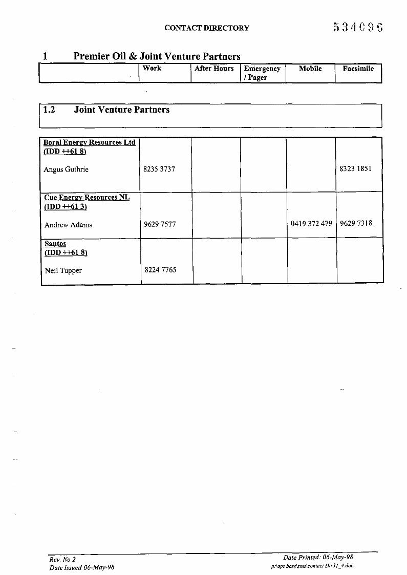
1
CONTACT DIRECTORY
Premier Oil & Joint Venture Partners
53 LIC9G
Work After Hours Emergency Mobile Facsimile/ Pager
Joint Venture Partners
Bora) Energy Resources Ltd(JDD ++618)
Angus Guthrie 82353737 83231851
Cue Energy Resources NLODD++613)
Andrew Adams 96297577 0419372 479 96297318.
Santos(JDD ++618)
Neil Tupper 82247765
Rev. No]Date Issued 06-May-98
Date Printed: 06-May-98p:I,OpS bass\smslcofltact Didl_4.doc
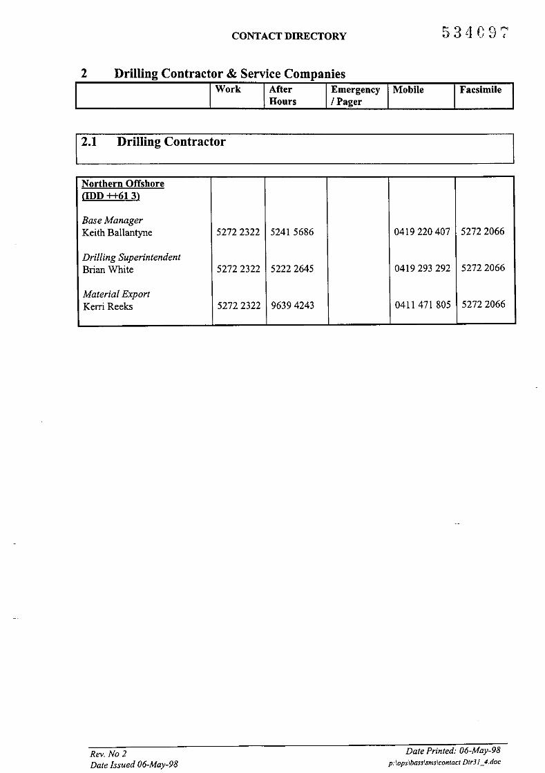
CONTACT DIRECTORY 53L1097
Drilling Contractor & Service Companies2Work After Emergency Mobile Facsimile
Honrs / Pager
Drilling Contractor
Northern OffshorelIDD ++613)
Base ManagerKeith Ballantyne 5272 2322 5241 5686 0419220407 5272 2066
Drilling SuperintendentBrian White 5272 2322 52222645 0419293292 5272 2066
Material ExportKerri Reeks 5272 2322 96394243 0411 471 805 5272 2066
Rev. No 2Date Issued 06-May-98
Date Printed: 06-May-98p:\opslbass\smslconract Dir31_4.doc

CONTACT DIRECTORY 534C98
2 Drilling Contractor & Service CompaniesWork After Emergency Mobile Facsimile
Hours I Pager
12.2 Service Companies
Schlumberger
Integrated ServiceCo-ordinator (03) (03)Paul Crerar 5272 2101 0411043049 5272 2058
Junior Drilling Engineer (03) (03)Peter Hoenninger 5272 2101 5272 2058
Cementing (08) (08)Leen Viot 94552144 94551728
Drilling Fluids (08) (08)Joe Barker 94552144 9455 1728
Wireline (03)Ryan Daniel 51432242
Testing (08) (08)Willie Ritchie 9353 1144 0419918654 93533450
Directional Survey/Drilling (03) (03)Jack Robertson 96966266 96900309
Mud Logging ( Geoservices) (08) (08)David Angus 92502010 92502715
Drill Bits ( Hughes) (08) (08)Stephen Lewis 94803724 0418128986' 93228082
Supply Vessels
Mermaid Marine (08) (08)Jim Carver 94317431 0418904317 94317432
Mermaid Raider 0145 0145117 240 217 240
Tidewater (08) (08)Reg McNee 92213865 0418335242 92213865
Rev, No 2Date Issued 06-May-98
Date Printed: 06-May-98p:\opslbass1sms\contact DirJ/_4. doc

CONTACT DIRECTORY 534G9D
2 Drilling Contractor & Service CompaniesWork After Emergency Mobile Facsimile
Hours I Pager
Helicopters
LloydsPerth - Graham Bowles (08) (08)
92682523 92682529
Adelaide - John Boag (08) (08). 83730700 0419828099 8373 3366
ROV
Australian UnderwaterContractors (08) (08) (08)Tim Gillingham 94307218 93898835 93407290Weather Reportin2
(03)Rob Cowie 98993140Oil Spill Advisor
(07) (07) (07)Terry Hayes 49394711 49394711 49394769Environmental Advisor
Dames & Moore (03) (03)Melbourne - David Gwyther 95105050 95105858
(08) (08)Perth - Ian Le Provost 9221 1630 9221 1639
Rental Tools
Austoil (08) (08)Wayne Watkins 9331 1444 93313087
Oilserv (TAM Packer) (08) (08)Keith McRae 94195933 94192250
Bits
Varel- Colin Hunter (08) (08)9331 1444 9331 3087
Hycalog - Tasman (08) (08)93306155 9330 1502
Reed - Tasman (08) (08)93306155 93301502
Reportin2 SoftwareIDS (08) (08)John Hanson 83592655 83592688
Rev. No 2Date Issued 06-May-98
Date Printed: 06-May-98p:\opslbasslsms\comact Did/_4.doc

CONTACT DIRECTORY
2 Drilling Contractor & Service CompaniesWork After Emergency Mobile Facsimile
Hours I Pager
Rig Positioning
Racal Survey (08) (08)Bryan Claridge 93447166 93448783
Casing Running
Premium Casing Services (08) (08) (08)Dave Littleton 9417 8411 94173364 0419944664 9417 7385
Wellhead Supplier
ABB Vetco (08) (08)Don Kunath 94796000 0412271621 94796111
Survey Equipment
Andergauge (08) (08)
John Grullis 93583383 0412074572 9356 1003
Testing Engineering
AWT (08) (08)
Cameron Manifold 92218144 0412000912 92218084
Fire Fighting Consultant
Boots & Coots Inc. (Houston) 00111713931 8884
Rev. No 2Date Issued 06-May-98
Date Printed: 06-May-98p:\ops\bass\smslcontact Dir31_4.doc

CONTACT DIRECTORY
3. Government Authorities
534101
Work After IEmergency! Mobile FacsimileHours Pager
3.1 Federal Authorities
Australian MaritimeSafety Authority !Australia Search andRescue(AusSAR) ODD ++61 2)
RCC - Aviation 62306899 1800815 62306868(24 hrs) 257 (24 hrs) 1800622 153
RCC - Maritime 62306811 1800641 62306868(24 hrs) 792 (24 hrs)
Canberra ODD ++61 2)Switchboard 62795000 1800641 62795866
(24 hrs) 792 (24 hrs)Manager Operations
Lipscombe, Ray 62795929 62306811 62690800 0418633 107 62795076Operations Coordinator
Beck, Greg 62795868 62690799 0418623353Senior Project andEnvironmental Officer
Wilde, Shayne 62795873 0419484446 62795866
Melbourne ODD ++61 3)Mackay, Bob 96855757
Airservices Anstralia -Flight ServicesAdelaide ODD ++61 8)
Switchboard 82387838 82344174(24 hrs)
Bureau of Air SafetyInvestigation fBASDBrisbane ODD ++ 61 7)
Air Safety InvestigatorCavenagh, Mike 3831 0628 1800011
034 (24 hr,)Melbourne ODD ++61 3)Air Safety Investigator
Sonneveld, John 96853606 1800011 9685 3611034 (24 hr,)
ACF Coastal SurveillanceODD++612)
Switchboard 1800061800 6275627562756000(24 hrs)
Rev. No 2Date Issued 06-May-98
Date Printed: 06-May-98p:opslbasslsms\cQntacl Didl_4. doc

CONTACT DIRECTORY
3. Government AuthoritiesWork After Emergency! Mobile I Facsimile
Hours Pager
3.1 Federal Authorities
Civil Aviation SafetvAuthority (CASA)Canberra aDD ++61 2)Acting Director
Pike, John 62171001National NumberODD++6l)
Switchboard 131 757CSIRO Division ofWildlife and EcologyCanberra aDD ++61 2)
Switchboard 62421600 6241 3343Department of PrimaryIndustries and EnergyCanberra ODD ++61 2)Assistant Secretary forExploration/Development
Lee, Mike 6272 4595 62310646 6272 4137Director Exploration,Petroleum and Fisheries
Furnell, Geoff 6272 4695 6272 4137Mineral ResourcesTasmania aDD ++61 3)
Switchboard 62338333 62338338
Bacon, Carol 62338326 6233 8338
3.2 Victorian State Authorities
Bureau of MeteorologyMelbourne aDD++61 3) .-
Switchboard 19001553363
Conservation and NaturalResources MelbourneaDD++613)
Switchboard 96378080Portland ODD ++61 3)
Switchboard 55233232 552348665523 1395
Country Fire Authority(CFA) Melbourne000++613)
Switchboard 92628444 000 (24 hrs)Fire DepartmentMelbourne aDD++61 3)
Switchboard 96622311 000 (24 hrs)
Rev. No 2Date Issued 06-May-98
Date Printed: 06-May-98p:'opslbasslsmslcontacl Dir31_4.doc

CONTACT DIRECTORY 53 LI103
3.2 Victorian State Authorities cont...
3. Government AuthoritiesWork After
Hours IEmergency! IMobilePager
IFacsimile ll
p
Police HeadquartersMelbourne @D++61 3) 11444 000 (24 hrs)
Department of NaturalResources andEnvironment.Agriculture. Energy andMineralsMelbourne (lDD++61 3)
Switchboard 96378000
\
Manager (Minerals andPetroleum)
King, Robert 94125069 015360773 94125152
Principal DrillingEngineer
Nadji, Ahmed 94125089 98482935 0412 110997 9412515298488905
Petroleum Engineer (ath)
(Emergency Response)Arvidson, Graham 94125012 97824323 94125152
EnvironmentalProtection AuthorityGeelong (++61 3)
Switchboard 52264825Melbourne @D++61 3)
Duty Officer 96285777
Emergency ..Response 016030Coordinator 96285777
#344 388Geelong PortGeelong (lDD ++61 3)
Switchboard 5221 5855Marine Supervisor
Trezise, Ian 52266220 0417391 794 5221 6883
Marine Controllers 52266300(24 hrs)52266341(24 hrs)
State EmergencyServiceColac @D ++61 3)
Switchboard 52312535
Rev. No 2Date Issued 06.May·98
Date Pnnted: 06·May-98p:\opslbasslsms\contaci Dir31_4.doc

CONTACT DIRECTORY
3. Government AuthoritiesWork After
HoursEmergency/ MobilePager
Facsimile
3.2 Victorian State Authorities cont...
Geelong ODD++61 3) 52264771Switchboard
Melbourne ODD++61 3)State Headquarters 96846659Switchboard 98900069
Marine Board ofVictoriaMelbourne ODD++61 3)
Director, MarinePollution and NavigationSafety
Turnbull, Capt. John 96559783 017 815 838 96556611
Victorian ChannelsAuthorityMelbourne ODD++61 3)
Emergency/Oil 96142861Pollution (24 hrs)
Head Office 96123512
Navigation ServicesManager
Muir, Tim 9612 3540 98085105 016030 018358301 96123550# 372 881
Paulusz, Charles 96123542 95805082 018345496 96123350
3.3 Victorian Local Authorities (Police and Shire Councils)..
Police HeadquartersGeelong ODD++61 3)
District Office 52253245 000 (24 hrs)
Melbourne ODD++61 3)
Switchboard 92476666 000 (24 hrs)City of Greater GeelongODD++613)
Switchboard 52270270Surfcoast CouncilTorquay ODD ++61 3)
Switchboard 5261 0600 0418524429 (24 hrs)
Rev. No 2Date Issued 06-May-98
Date Printed: 06-May-98p: lopslbasslsms\contact DidJ_4.doc

CONTACT DIRECTORY
3. Government Authorities
534105
Work After IEmergency! IMobile IFacsimileHonrs Pager
13.4 Tasmanian State Authorities
Anstralian MaritimeSafety AnthorityDevonport @D ++61 3)
Switchboard 6424 1597 64248009Burean of MeteorologyMelbourne ODD++61 3)
Weather by Fax 1800061437
Department ofEnvironmental & LandManagement North West@D++613)
Switchboard 6458 1100 018 142617 6458142064581415
Prospect ODD++61 3)Sal1ans, Steve 63365328 6344 8109
Environmental PollutionIncidents andComplaints - Burnie TAS@D++613)
1800005Switchboard 141 (24hrs)
Fire DepartmentBurnie ODD ++61 3)
Switchboard 64346700 000 (24 hrs)
Marine Board TasmaniaODD++613)
Switchboard 6461 1155Parks and Wildlife --
Burnie TAS ODD++61 3)
Switchboard 6233 8011Police HeadquartersHobart TAS@D++613)
Switchboard 62302111Port Authorities - BurnieTAS ODD ++61 3)
Switchboard 64347300 64347373
Devonport @D ++61 3)
Harbour Authority 64240911 64240911
Nasat Marine Supervisor 64240911State Security ServiceTasmania @D++61 3)
Switchboard 6437 1274 0418303447
Rev_ No 2Date Issued 06-May-98
Date Printed: 06-May-98p:lopslbasslsmslcontact Didl_4.doc
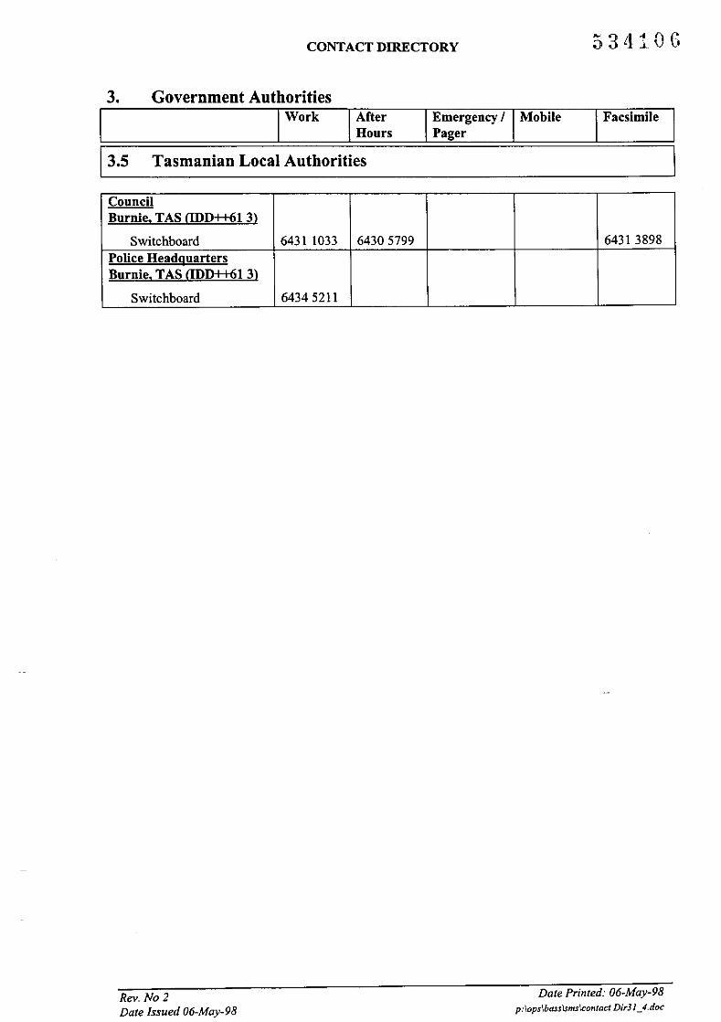
3.
CONTACT DIRECTORY
Government Authorities
53 tll0G
Work AfterHours
Emergency I MobilePager
Facsimile
13.5 Tasmanian Local Authorities
CouncilBurnie. TAS (IDD++61 3)
Switchboard 6431 1033 64305799 64313898Police HeadquartersBurnie. TAS (IDD++613)
Switchboard 64345211
Rev. No 2Date Issued 06-May-98
Date Printed: 06-May-98p:\opslbass\sms\contact Dir31_4.doc

4.
CONTACT DIRECTORY
Oil Spill Agencies and Specialists
534107
Work AfterHours
[4.1 NATPLAN/State Combat Committee
Emergency / MobilePager
Facsimile
Australian Maritime SafetyAuthorityCanberra ODD++61 2)Manager MarineEnvironment Protection Unit
Lipscombe, Ray 62795929 62306811 62690800 0418633 107 62795076Acting General Manager
Baird, David 62795935 62690843 0418822824 62795076Senior Project andEnvironmental Officer
Wilde, Shayne 62795873 0419484446 62795866
Admin Clerk/PAStiller, Cheryl 62795069
Melbourne (lDD ++61 3)Mackay, Bob 96855757
Geelong PortGeelong (lDD++61 3)
Switchboard 5221 5855
Marine SupervisorTrezise, Ian 52266220 0417391 794 52216883
Marine Controllers 52266300(24 hrs)52266341(24 hrs)
4.2 AMOSC
AMOSC (AustralianMarine Oil Spill Centre) ..Geelong (lDD ++61 3)
Switchboard 5272 1555 5272 1839
Duty Officer 5272 1555 016379328 5272 1839
Manager/Overall Industry(24 hrs)
CoordinatorBlackmore, Don 5272 1555 016379328 0418398363 5272 1839
4.3 Oilmap Spill Trajectory Model
GEMSMelbourne (lDD ++61 3)Oil Spill TrajectoryModelling Consultant
Hubbert, Grahame 98440535 0418366336 98442630(24hrs)
Rev. No 2Date Issued 06-May-98
Date Printed: 06-May-98p:\opslbass\sms\contact Dir3J_4.doc

4.
CONTACT DIRECTORY
Oil Spill Agencies and Specialists
-3'1~O\i;) L-.l. :..-)
Work AfterHours
Emergency! MobilePager
Facsimile
4.4 Oil Spill Operations and Management Specialists
Altona MarineMelbourne @D ++61 3)Manager (24 hrs)
Peins, Alf 93982026 0419566250 93892026Capricorn EnvironmentalYapoon (lDD ++61 7)
Switchboard 49394711 49394769(24 hrs)
Hayes, Terry 49394711 019631206 49394769
Hartec - United States- Anchorage Alaska(lDD++l)
Hartley, Brett 907 9075223031 5223494(24 hrs)
Switchboard9075223494
Oops Inc.Louisiana USA(lDD ++1504)
O'Brien, Jim 3689845 3680630(24 hrs)
Switchboard 3689845 3680630
Oest Consulting GroupMelbourne (lDD ++61 3)Manager EmergencyResponse
Rigby, Gary 96144133 52783121 0417 313 610 961451335277 2303(aIh)
Switchboard 96144133 96145133
4.5 Oil Spill Environment and Cleanup Specialists
Esso Australia Ltd lEAL)Melbourne (lDD ++61 3)
Switchboard 92703333 92703995
Acting EnvironmentalAdvisor
Terrens, Greg 92703509 95845550 016030 92703590#312023
John WardropMelbourne (lDD ++61 3)
Wardrop, John 52824074 015 83064352824075
Rev. No 2Date Issued 06-May-98
Date Printed: 06-May-98p:\ops\basslsmslcontact DidJ_4.doc

4.
CONTACT DIRECTORY
Oil Spill Agencies and SpecialistsWork After
HoursEmergency/ MobilePager
Facsimile
4.5 Oil Spill Environment and Cleanup Specialists
OCCSeattle, WashingtonUSA aDD ++1206)
Owens, Ed 8422951 8426255 8422861
Switchboard 8422951 8422861
4,6 Other Agencies
Australian Maritime SafetyAuthorityAustralia Search andRescue(AusSAR) aDD ++ 61 2)
RCC - Aviation 62306899 1800815257 62306868(24 hrs) (24hrs) 1800622153
RCC - Maritime 62306811 1800641792 62306868(24 hrs) (24 hrs)
Canberra aDD ++61 2)Marine EnvironmentProtection ServicesAustralian Maritime SafetyAuthorityPOBox 1108Belconnen, ACT 2616
Operations CoordinatorBeck, Greg 62795868 62690799 0418623353
Manager OperationsLipscombe, Ray 62795929 62306811 62690800 0418633 107 -62795076
Switchboard 62795000 1800641792 0419484446 62306868
Senior Project and(24hrs)
Environmental Officer
Wilde, Shayne 62795873 62795866
Rev. No 2Date Issued 06-May-98
Date Printed: 06-May-98p:\opslbasslsms\contact DirJ/_4.doc

CONTACT DIRECTORY
4. Oil Spill Agencies and Specialists
e:3;1~~(\~J 4- . ..J... 1.. -'
Work IAfter Emergency! IMobile FacsimileIHours Pager
14.6 Other Agencies
EARL fEast Asia ResponseLtd) Singapore anD++ 65)2 Jalan SamulunSingapore 2262
Manager for TechnicalServices (24 hrs)
Chew, Capt. J.K. 2661566 2662312
Manager - Centre ServicesOoi Beng Hong, Capt. (24 hrs)Patrick 2661566 2662312
CEOSeowhood, Jin 2661566 2662312
(24 hrs)
SwitchboardlDuty Off. 266 1566 2662312Oil Spill Response (OSR)Ltd Southampton UKanD ++44 1703)
Lower William StreetSouthampton SOl4 5 QEEngland
Switchboard 331 551 1523 523 523 331972(24 hrs) #604319
4.7 Bird Rehabilitation
Taronga Park Zoo -
Sydney aDD ++ 61 2)
Switchboard 99692777 9925 3911 018672 323 99697515# 299 011
Waldraven, Emma 9978 4609 98073558 9925 3911 019129956 99784613#299 Oil
Hall, Libbi 99784751 99079496 9978 4516Penguin ParadePhillip Island aDD ++61 3)
Switchboard 59568300 59568394
Rev. No 2Date Issued 06-May-98
Date Printed: 06-May-98p:\opslbass\smslcontact Did 1_4.doc
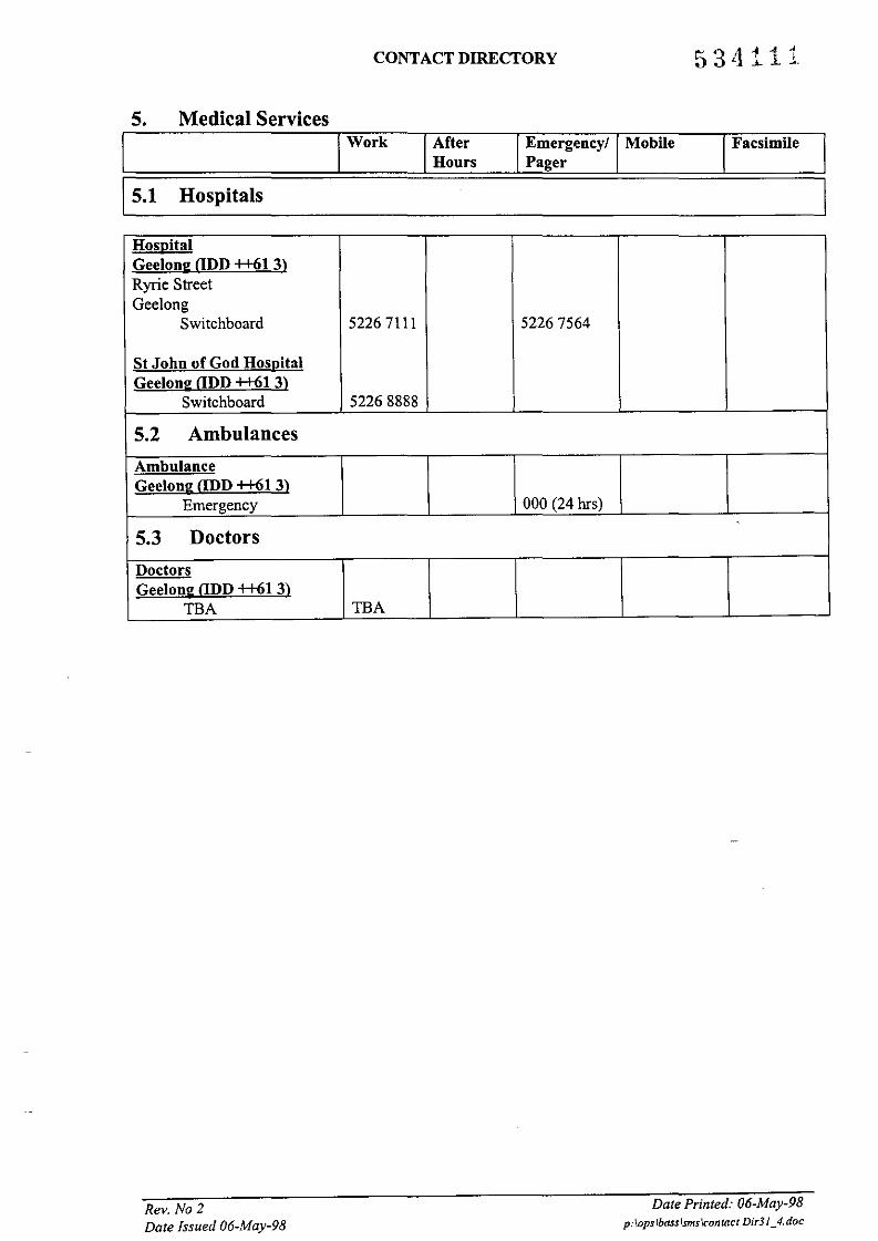
5. Medical Services
CONTACT DIRECTORY 534111
I Work IAfter IEmergency! IMobile Facsimile IHours Pager
IL5_,l__H_O_s_p_it_al_s 1
HospitalGeelong (lDD ++61 3)Ryrie StreetGeelong
Switchboard 52267111 52267564
St John of God HospitalGeelong (lDD ++61 3)
Switchboard 52268888
5.2 Ambulances
AmbulanceGeelong ODD ++61 3)
Emergency 000 (24 hrs)
5.3 Doctors
DoctorsGeelong (lDD ++61 3)
TBA TBA
Rev. No 2Date Issued 06-May-98
Date Printed: 06-May-98p:\opslbasslsms\contact Dir31_4. doc

CONTACT DIRECTORY
6. Aircraft Services
16.1 Helicopters
Work AfterHours I
Emergency/ I MobilePager
IFacsimile ~I
Aircraft Australia FlightServicesAdelaide (IDD++61 8)
Switchboard 82387838 82344174(24 hrs)
Perth (IDD ++61 8)Centre Coordination 94768609 94768606
(24 hrs)
94765926(24 hrs)
94768607Lloyd Helicopters GroupAdelaide Head Office(IDD ++618)Operations LogisticsManager
Martin, Doug 83730700 82705381 018855195 8373 1119
Operations Logistics OfficerBoag, John 83730700 8271 3242 018855195 8373 1119
Rev. No 1Date Issued 06-May-98
Date Printed: 06-May-98p:\opslbass\smslcontQct Dir3/_4.doc

CONTACT DIRECTORY
7. Marine ServicesWork IAfter
Hours IEmergency! IMobilePager
IFacsimile
Lewmarine Geelong@D++613)
Switchboard 5221 1577Tidewater Port JacksonPerth aDD ++61 8)
Switchboard 92212822
Acting Marine OperationsManager
Tyler, Ed 92217619 93159672 015334825 92213865Australian OffshoreServices MelbourneaDD++613)
Switchboard 92541666 92541546 016376434 96869279
Operations Manager
Hall, Richard 92541666 98441857 0412568780 96869279
Burgess, Dick 9254 1547 95285982 018369787 96869279
Homsey, Jack 92541666 94584237 0412458423 96869268
Rev. No2Date Issued 06-May-98
Date Printed: 06-May-98p:\opslbasslsmslcontact Dir3J_4.doc

CONTACT DIRECTORY
8. Petroleum Exploration and Production Companies and AssociationsIWork After Emergency! Mobile Facsimile I
Hours Pager
Apache Energy LtdPerth ODD ++61 8)Level 3256 St Georges TcePerth WA 6000
Switchboard 94227222 94227444Operations Manager
Lake, Bruce 94227206 94227445Boral Energy Resources LtdAdelaide ODD ++61 8)3rd Floor, Hospitality House60 Hindmarsh SquareAdelaide SA 5000
Switchboard 82353737 8223 1851
Manager for ExplorationAustralia West
Bouer, Jennie 8235 3737 82231851Manager for ExplorationAustralia South
Lovibond, Rod 82353737 8223 1851Manager ofOil and GasProduction
Wearne, Geoff 8235 3737 8223 1851
BPMelbourne ODD ++61 3)360 Elizabeth StreetMelbourne VIC 3000Terminals and DistributionManager
Watton, Mike 92683858 92683524
Esso Australia Ltd rEAL) -
Melbourne ODD ++61 3)
12 Riverside QuayMelbourne VIC 3006
Switchboard 92703333 92703995
Drilling Operations Manager 016030Jenkins, Bob 92703422 #310607 0417347499 92703593
Novus West Australia PILDampier Supply BaseODD ++618)
Switchboard 91444099 91444088
Board, Dal 91444099 91854194 018937518 9144 4088
Rev. No 2Date Issued 06-May-98
Date Printed: 06-May-98p:\opslbass1smslcontacl Dir3 J_4.doc

CONTACT DIRECTORY
8. Petroleum Exploration and Production Companies and AssociationsWork After Emergency! Mobile Facsimile
Hours Pager
Onslow Supply Base(lDD ++618)
Switchboard 91846092 91846196Mazneiu, Peter 91846192 91846196
Perth (lDD ++ 61 8)Switchboard 94867700 94869800
Emergency Response 94200746 94200748Centre (Voice mail)
Production SuperintendentHerrera, G 94867700 93060979 93244813 0411 757 874 94869800
Drilling ManagerMackay, Dave 94867700 93244813 94869800
Safety ManagerShand, J 94867700 93505768 93244813 0411 757864 94869800
Mobil Exploration andProducing Australia PtyLtd Perth ODD ++61 8)29th Floor, QVl Building250 St Georges TcePerth WA 6000
Switchboard 94249200 94249203Drilling Superintendent
Honore, Royal 94249403 94249566Operations Manager TeamLeader
Goodacre, Jack 94249273 94249544Phillips Australian Oil -CompanyMelbourne (lDD ++61 3)StaffDrilling Director
Curry, Bin 96526537 98735684 96526124Perth (lDD ++ 61 8)Level 2, 28-42 Ventnor AveWest Perth WA 6005
Switchboard 94236666 94236677General Manager
Storer, Fred 94236650 94236677Santos LtdAdelaide (lDD ++ 61 8)Santos House91 King William StAdelaide SA 5001Drilling Manager
Gamblen, Jeff 82247195 82247141
Rev. No 2Date Issued 06-May-98
Date Prznted: 06-May-98p:\opslbass\sms\contact Dir31_4. doc
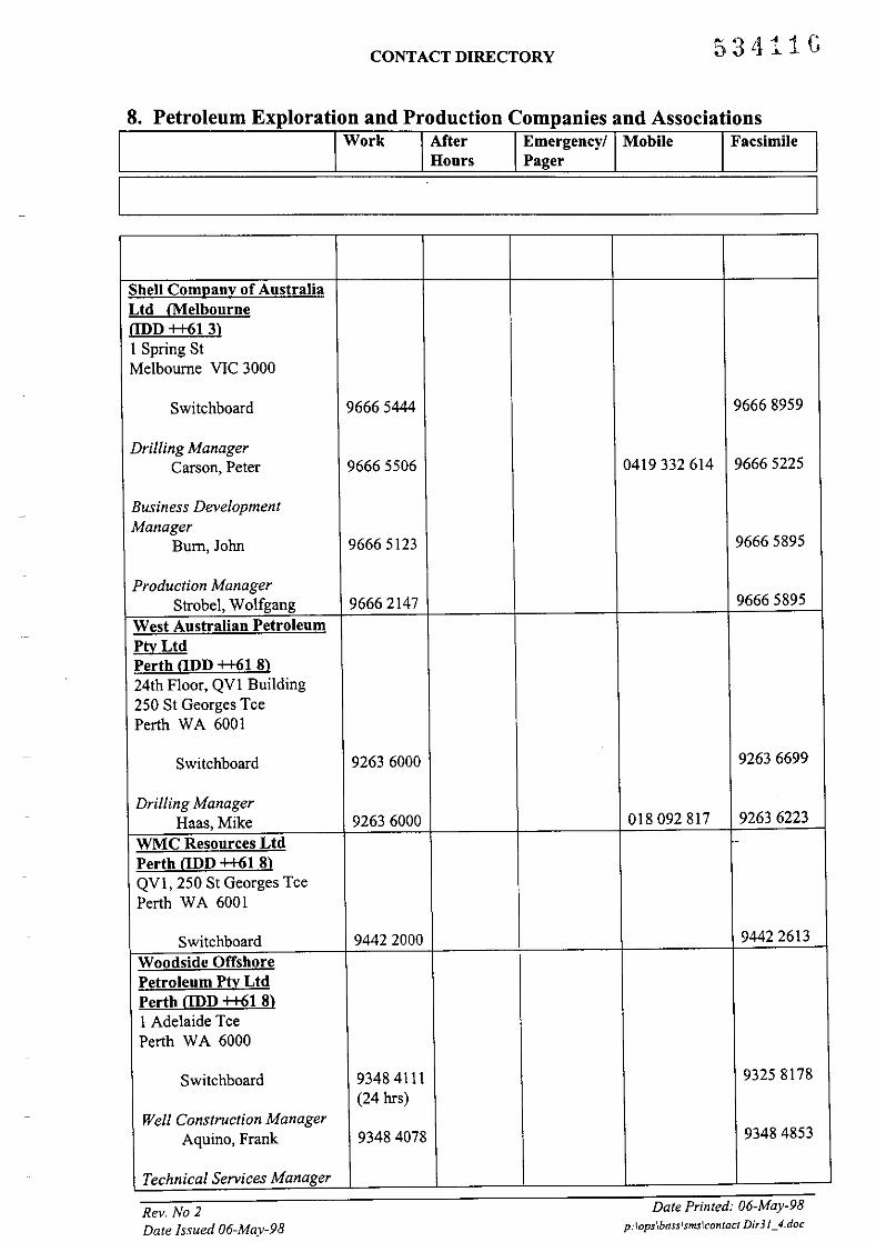
CONTACT DIRECTORY 53tl11G
8. Petroleum Exploration and Production Companies and AssociationsWork IAfter IEmergency! IMobile IFacsimile I
Hours Pager
'--- 1
Shell Company of AustraliaLtd <Melbourne@D++613)I Spring StMelbourne VIC 3000
Switchboard 96665444 96668959
Drilling ManagerCarson, Peter 96665506 0419332614 96665225
Business DevelopmentManager
Burn, John 96665123 96665895
Production ManagerStrobel, Wolfgang 96662147 96665895
West Australian PetroleumPtyLtdPerth aDD ++61 8)24th Floor, QVI Building250 St Georges TcePerth WA 6001
Switchboard 92636000 92636699
Drilling ManagerHaas, Mike 92636000 018092 817 92636223
WMC Resources Ltd -
Perth aDD ++61 8)QVI, 250 St Georges TcePerth WA 6001
Switchboard 94422000 94422613
Woodside OffshorePetroleum Pty LtdPerth aDD ++61 8)I Adelaide TcePerth WA 6000
Switchboard 93484111 93258178
(24 hrs)Well Construction Manager
Aquino, Frank 93484078 93484853
Technical Services Manager
Rev. No 2Date Issued 06-May-98
Date Prmted: 06-May-98p:\ops\basslsms\contQct Did!_4.doc

CONTACT DIRECTORY 534117
8. Petroleum Exploration and Production Companies and AssociationsTwork TAfter Emergency! Mobile Facsimile
Hours Pager
Woodall-Mason, Nick 93484088 93485082
Rev. No 2Date Issued 06-May-98
Date Printed: 06-May-98p:\ops\bass"smslcontact Dir31_4.doc