Basics to Electricity
56
Table of Contents Introduction .............................................................................. 2 Conductors and Insulators ........................................................ 3 Current, Voltage, and Resistance .............................................. 6 Ohm’s Law ............................................................................. DC Circuits.............................................................................. 3 Magnetism ............................................................................. 20 Alternating Current ................................................................. 23 Inductance and Capacitance ................................................... 30 Reactance and Impedance ..................................................... 35 Series and Parallel R-L-C Circuits............................................. 40 Power and Power Factor in an AC Circuit ................................ 43 Transformers ........................................................................... 47 Review Answers ..................................................................... 53 Final Exam .............................................................................. 56
-
Upload
makwanagaurav185779 -
Category
Documents
-
view
16 -
download
0
description
Every fundamental you need to know about the electricity and its concepts.
Transcript of Basics to Electricity
Table of Contents
Introduction...............................................................................2
Conductors.and.Insulators.........................................................3
Current,.Voltage,.and.Resistance...............................................6
Ohm’s.Law..............................................................................
DC.Circuits...............................................................................3
Magnetism..............................................................................20
Alternating.Current..................................................................23
Inductance.and.Capacitance....................................................30
Reactance.and.Impedance......................................................35
Series.and.Parallel.R-L-C.Circuits..............................................40
Power.and.Power.Factor.in.an.AC.Circuit.................................43
Transformers............................................................................47
Review.Answers......................................................................53
Final.Exam...............................................................................56
2
Introduction
Welcome.to.the.first.course.in.the.STEP.series,.Siemens.Technical.Education.Program.designed.to.prepare.our.distributors.to.sell.Siemens.Industry,.Inc..products.more.effectively..This.course.covers.Basics of Electricity.and.is.designed.to.prepare.you.for.courses.on.Siemens.Industry,.Inc..products.
Upon.completion.of.Basics.of.Electricity.you.will.be.able.to:
•. Explain.the.difference.between.conductors.and.insulators•. Use.Ohm’s.law.to.calculate.current,.voltage,.and.
resistance•. Calculate.equivalent.resistance.for.series,.parallel,.or.
series-parallel.circuits•. Calculate.voltage.drop.across.a.resistor•. Calculate.power.given.other.basic.values•. Identify.factors.that.determine.the.strength.and.polarity.of.
a.current-carrying.coil’s.magnetic.field•. Determine.peak,.instantaneous,.and.effective.values.of.an.
AC.sine.wave•. Identify.factors.that.effect.inductive.reactance.and.
capacitive.reactance.in.an.AC.circuit•. Calculate.total.impedance.of.an.AC.circuit•. Explain.the.difference.between.real.power.and.apparent.
power.in.an.AC.circuit•. Calculate.primary.and.secondary.voltages.of.single-phase.
and.three-phase.transformers•. Calculate.the.required.apparent.power.for.a.transformer
This.knowledge.will.help.you.better.understand.customer.applications..In.addition,.you.will.be.better.able.to.describe.products.to.customers.and.determine.important.differences.between.products..
After.you.have.completed.this.course,.if.you.wish.to.determine.how.well.you.have.retained.the.information.covered,.you.can.complete.a.final.exam.online.as.described.later.in.this.course..If.you.pass.the.exam,.you.will.be.given.the.opportunity.to.print.a.certificate.of.completion.from.your.computer.
3
Conductors and Insulators
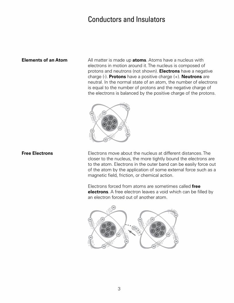
Elements of an Atom. All.matter.is.made.up.atoms..Atoms.have.a.nucleus.with.electrons.in.motion.around.it..The.nucleus.is.composed.of.protons.and.neutrons.(not.shown)..Electrons.have.a.negative.charge.(-)..Protons.have.a.positive.charge.(+)..Neutrons.are.neutral..In.the.normal.state.of.an.atom,.the.number.of.electrons.is.equal.to.the.number.of.protons.and.the.negative.charge.of.the.electrons.is.balanced.by.the.positive.charge.of.the.protons.
Free Electrons. Electrons.move.about.the.nucleus.at.different.distances..The.closer.to.the.nucleus,.the.more.tightly.bound.the.electrons.are.to.the.atom..Electrons.in.the.outer.band.can.be.easily.force.out.of.the.atom.by.the.application.of.some.external.force.such.as.a.magnetic.field,.friction,.or.chemical.action.
Electrons.forced.from.atoms.are.sometimes.called.free electrons..A.free.electron.leaves.a.void.which.can.be.filled.by.an.electron.forced.out.of.another.atom..
4
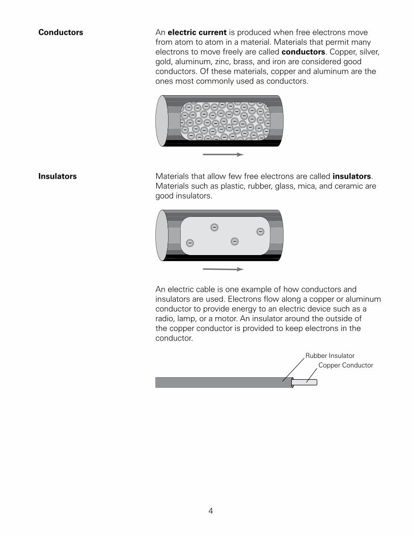
Conductors. An.electric current.is.produced.when.free.electrons.move.from.atom.to.atom.in.a.material..Materials.that.permit.many.electrons.to.move.freely.are.called.conductors..Copper,.silver,.gold,.aluminum,.zinc,.brass,.and.iron.are.considered.good.conductors..Of.these.materials,.copper.and.aluminum.are.the.ones.most.commonly.used.as.conductors..
Insulators. Materials.that.allow.few.free.electrons.are.called.insulators..Materials.such.as.plastic,.rubber,.glass,.mica,.and.ceramic.are.good.insulators.
An.electric.cable.is.one.example.of.how.conductors.and.insulators.are.used..Electrons.flow.along.a.copper.or.aluminum.conductor.to.provide.energy.to.an.electric.device.such.as.a.radio,.lamp,.or.a.motor..An.insulator.around.the.outside.of.the.copper.conductor.is.provided.to.keep.electrons.in.the.conductor.
Rubber InsulatorCopper Conductor
5
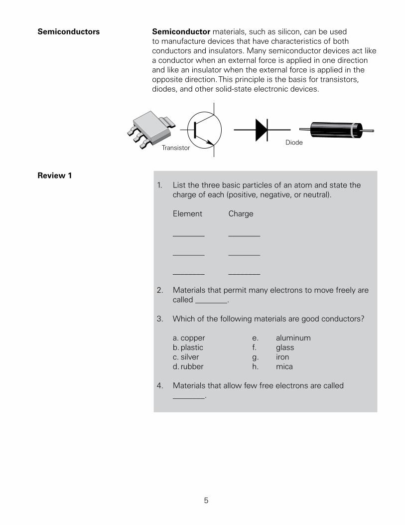
Semiconductors. Semiconductor.materials,.such.as.silicon,.can.be.used.to.manufacture.devices.that.have.characteristics.of.both.conductors.and.insulators..Many.semiconductor.devices.act.like.a.conductor.when.an.external.force.is.applied.in.one.direction.and.like.an.insulator.when.the.external.force.is.applied.in.the.opposite.direction..This.principle.is.the.basis.for.transistors,.diodes,.and.other.solid-state.electronic.devices..
TransistorDiode
Review 1.. List.the.three.basic.particles.of.an.atom.and.state.the.
charge.of.each.(positive,.negative,.or.neutral).... Element.. Charge. . . . .. ________. ________
. ________. ________
. ________. ________
2.. Materials.that.permit.many.electrons.to.move.freely.are.called.________.
3.. Which.of.the.following.materials.are.good.conductors?
. a..copper. . e.. aluminum
. b..plastic.. . f.. glass
. c..silver. . . g.. iron
. d..rubber.. . h.. mica
4.. Materials.that.allow.few.free.electrons.are.called. ________.
6
Current, Voltage, and Resistance
All.materials.are.composed.of.one.or.more.elements..An.element.is.a.material.made.up.of.one.type.of.atom..Elements.are.often.identified.by.the.number.of.protons.and.electrons.in.one.atom.of.the.element..A.hydrogen.atom,.for.example,.has.only.one.electron.and.one.proton..An.aluminum.atom.has.3.electrons.and.3.protons..An.atom.with.an.equal.number.of.electrons.and.protons.is.electrically.neutral..
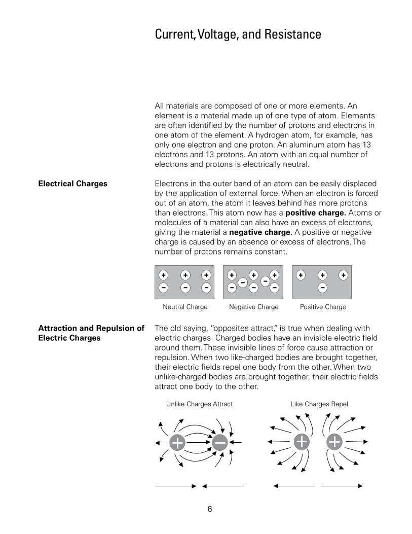
Electrical Charges. Electrons.in.the.outer.band.of.an.atom.can.be.easily.displaced.by.the.application.of.external.force..When.an.electron.is.forced.out.of.an.atom,.the.atom.it.leaves.behind.has.more.protons.than.electrons..This.atom.now.has.a.positive charge..Atoms.or.molecules.of.a.material.can.also.have.an.excess.of.electrons,.giving.the.material.a.negative charge..A.positive.or.negative.charge.is.caused.by.an.absence.or.excess.of.electrons..The.number.of.protons.remains.constant.
Neutral Charge Negative Charge Positive Charge
Attraction and Repulsion of. The.old.saying,.“opposites.attract,”.is.true.when.dealing.with.Electric Charges. electric.charges..Charged.bodies.have.an.invisible.electric.field.
around.them..These.invisible.lines.of.force.cause.attraction.or.repulsion..When.two.like-charged.bodies.are.brought.together,.their.electric.fields.repel.one.body.from.the.other..When.two.unlike-charged.bodies.are.brought.together,.their.electric.fields.attract.one.body.to.the.other..
Unlike Charges Attract Like Charges Repel
7
The.interaction.of.electrical.charges.is.dependent.upon.both.the.both.the.amount.of.each.charge.and.the.distance.between.charges..The.greater.the.amount.of.each.charge.the.more.charged.objects.attract.or.repel.one.another..However.this.interaction.is.inversely.proportional.to.the.square.of.the.distance.between.charges..
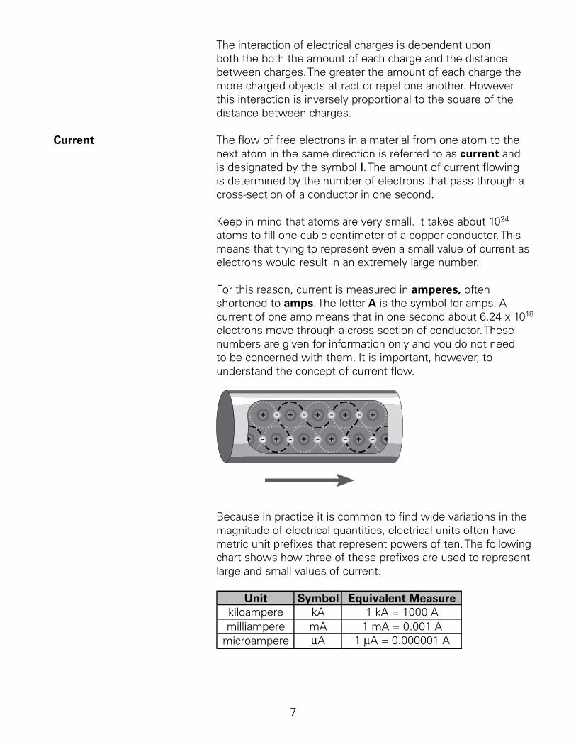
Current. The.flow.of.free.electrons.in.a.material.from.one.atom.to.the.next.atom.in.the.same.direction.is.referred.to.as.current.and.is.designated.by.the.symbol.I..The.amount.of.current.flowing.is.determined.by.the.number.of.electrons.that.pass.through.a.cross-section.of.a.conductor.in.one.second..
Keep.in.mind.that.atoms.are.very.small..It.takes.about.024.
atoms.to.fill.one.cubic.centimeter.of.a.copper.conductor..This.means.that.trying.to.represent.even.a.small.value.of.current.as.electrons.would.result.in.an.extremely.large.number.
For.this.reason,.current.is.measured.in.amperes,.often.shortened.to.amps..The.letter.A.is.the.symbol.for.amps..A.current.of.one.amp.means.that.in.one.second.about.6.24.x.08.electrons.move.through.a.cross-section.of.conductor..These.numbers.are.given.for.information.only.and.you.do.not.need.to.be.concerned.with.them..It.is.important,.however,.to.understand.the.concept.of.current.flow.
Because.in.practice.it.is.common.to.find.wide.variations.in.the.magnitude.of.electrical.quantities,.electrical.units.often.have.metric.unit.prefixes.that.represent.powers.of.ten..The.following.chart.shows.how.three.of.these.prefixes.are.used.to.represent.large.and.small.values.of.current.
Unit Symbol Equivalent Measurekiloampere kA 1 kA = 1000 Amilliampere mA 1 mA = 0.001 A
microampere µA 1 µA = 0.000001 A
8
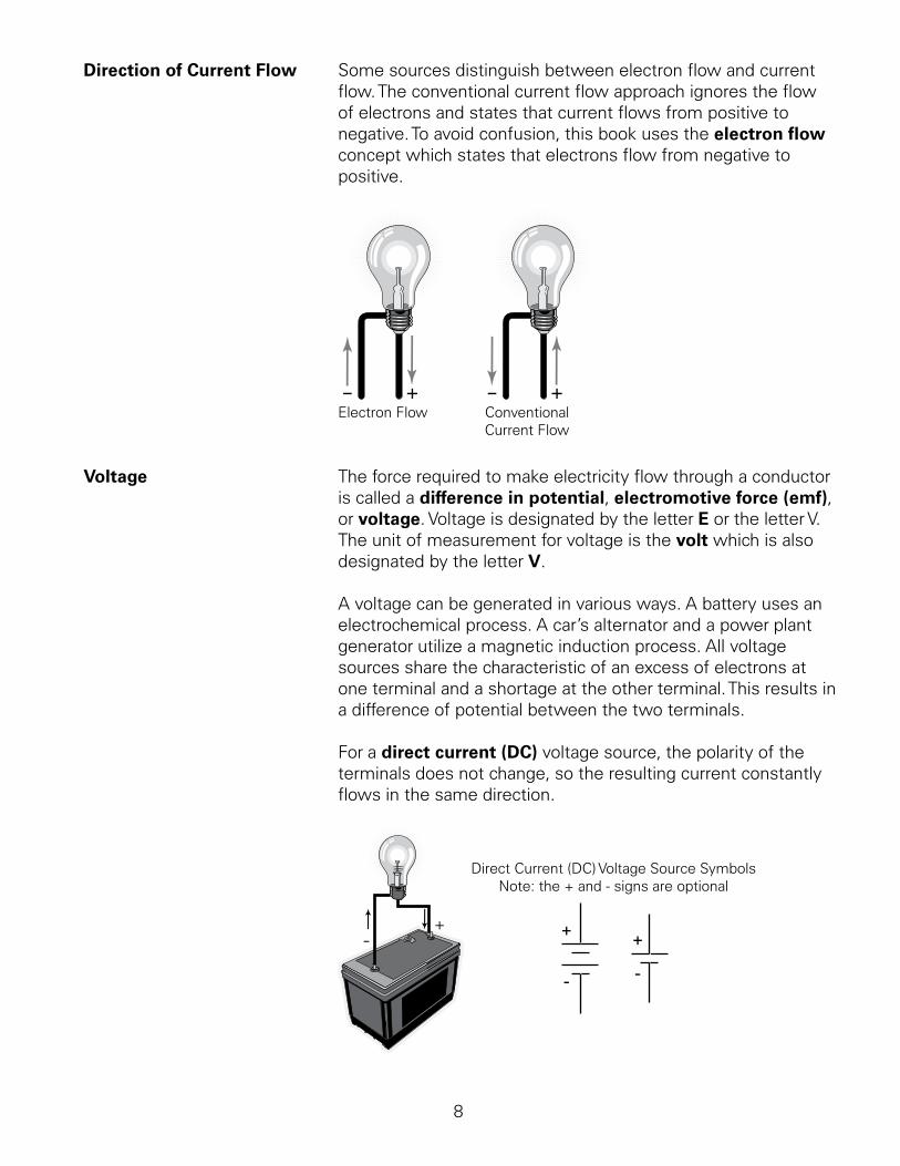
Direction of Current Flow. Some.sources.distinguish.between.electron.flow.and.current.flow..The.conventional.current.flow.approach.ignores.the.flow.of.electrons.and.states.that.current.flows.from.positive.to.negative..To.avoid.confusion,.this.book.uses.the.electron flow.concept.which.states.that.electrons.flow.from.negative.to.positive.
Electron Flow ConventionalCurrent Flow
Voltage The.force.required.to.make.electricity.flow.through.a.conductor.is.called.a.difference in potential,.electromotive force (emf),.or.voltage..Voltage.is.designated.by.the.letter.E.or.the.letter.V..The.unit.of.measurement.for.voltage.is.the.volt.which.is.also.designated.by.the.letter.V.
A.voltage.can.be.generated.in.various.ways..A.battery.uses.an.electrochemical.process..A.car’s.alternator.and.a.power.plant.generator.utilize.a.magnetic.induction.process..All.voltage.sources.share.the.characteristic.of.an.excess.of.electrons.at.one.terminal.and.a.shortage.at.the.other.terminal..This.results.in.a.difference.of.potential.between.the.two.terminals..
For.a.direct current (DC).voltage.source,.the.polarity.of.the.terminals.does.not.change,.so.the.resulting.current.constantly.flows.in.the.same.direction.
+
-
+
-
Direct Current (DC) Voltage Source SymbolsNote: the + and - signs are optional
-+
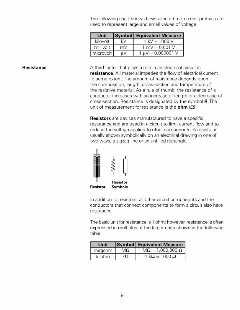
The.following.chart.shows.how.selected.metric.unit.prefixes.are.used.to.represent.large.and.small.values.of.voltage.
Unit Symbol Equivalent Measurekilovolt kV 1 kV = 1000 Vmillivolt mV 1 mV = 0.001 V
microvolt µV 1 µV = 0.000001 V
Resistance.. A.third.factor.that.plays.a.role.in.an.electrical.circuit.is.resistance..All.material.impedes.the.flow.of.electrical.current.to.some.extent..The.amount.of.resistance.depends.upon.the.composition,.length,.cross-section.and.temperature.of.the.resistive.material..As.a.rule.of.thumb,.the.resistance.of.a.conductor.increases.with.an.increase.of.length.or.a.decrease.of.cross-section..Resistance.is.designated.by.the.symbol.R..The.unit.of.measurement.for.resistance.is.the.ohm.(W)..
Resistors.are.devices.manufactured.to.have.a.specific.resistance.and.are.used.in.a.circuit.to.limit.current.flow.and.to.reduce.the.voltage.applied.to.other.components..A.resistor.is.usually.shown.symbolically.on.an.electrical.drawing.in.one.of.two.ways,.a.zigzag.line.or.an.unfilled.rectangle..
ResistorResistorSymbols
In.addition.to.resistors,.all.other.circuit.components.and.the.conductors.that.connect.components.to.form.a.circuit.also.have.resistance.
The.basic.unit.for.resistance.is..ohm;.however,.resistance.is.often.expressed.in.multiples.of.the.larger.units.shown.in.the.following.table.
Unit Symbol Equivalent Measuremegohm MΩ 1 MΩ = 1,000,000 Ωkilohm kΩ 1 kΩ = 1000 Ω
0
Review 2 .. A.material.that.has.an.excess.of.electrons.has.a. ________.charge.
2.. A.material.that.has.a.deficiency.of.electrons.has.a.________.charge.
3.. Like.charges.________.and.unlike.charges.________.
4.. ________.is.the.force.that,.when.applied.to.a.conductor,.causes.current.flow.
5.. Electrons.move.from.________.to.________.
6.. Identify.the.basic.unit.of.measure.for.each.of.the.items.shown.below.
. a..Resistance. ________
. b..Current. ________
. c..Voltage. ________
Ohm’s Law
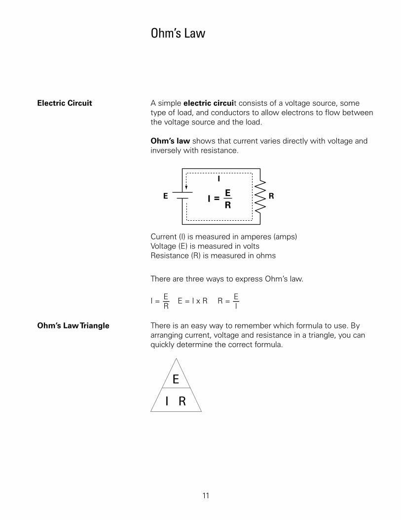
Electric Circuit. A.simple.electric circuit.consists.of.a.voltage.source,.some.type.of.load,.and.conductors.to.allow.electrons.to.flow.between.the.voltage.source.and.the.load.
Ohm’s law.shows.that.current.varies.directly.with.voltage.and.inversely.with.resistance.
Current (I) is measured in amperes (amps)Voltage (E) is measured in voltsResistance (R) is measured in ohms
I
RE IER
=
There.are.three.ways.to.express.Ohm’s.law..
I = ER
E = I x R R = EI
Ohm’s Law Triangle. There.is.an.easy.way.to.remember.which.formula.to.use..By.arranging.current,.voltage.and.resistance.in.a.triangle,.you.can.quickly.determine.the.correct.formula..
2
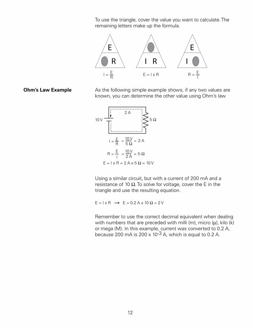
To.use.the.triangle,.cover.the.value.you.want.to.calculate..The.remaining.letters.make.up.the.formula.
I = ER
E = I x R R = EI
Ohm’s Law Example. As.the.following.simple.example.shows,.if.any.two.values.are.known,.you.can.determine.the.other.value.using.Ohm’s.law.
10 V 5 Ω
2 A
I = ER
= 2 A=10 V5 Ω
R =EI
= 5 Ω=10 V2 A
E = I x R = 2 A x 5 Ω = 10 V
Using.a.similar.circuit,.but.with.a.current.of.200.mA.and.a.resistance.of.0.W..To.solve.for.voltage,.cover.the.E.in.the.triangle.and.use.the.resulting.equation.
E = I x R E = 0.2 A x 10 Ω = 2 V
Remember.to.use.the.correct.decimal.equivalent.when.dealing.with.numbers.that.are.preceded.with.milli.(m),.micro.(m),.kilo.(k).or.mega.(M)..In.this.example,.current.was.converted.to.0.2.A,.because.200.mA.is.200.x.0-3.A,.which.is.equal.to.0.2.A.

3
DC Circuits
Series Circuits. A.series circuit.is.formed.when.any.number.of.devices.are.connected.end-to-end.so.that.there.is.only.one.path.for.current.to.flow..The.following.illustration.shows.five.resistors.connected.in.series..There.is.one.path.for.current.flow.from.the.negative.terminal.of.the.voltage.source.through.all.five.resistors.and.returning.to.the.positive.terminal.
11 kΩ 2 kΩ 2 kΩ 100 Ω 1k Ω
R1 R2 R3 R4 R5
Total Resistance = Rt = R1 + R2 + R3 + R4 + R5
Rt = 11,000 Ω + 2000 Ω + 2000 Ω + 100 Ω + 1000 Ω
Rt = 16,100 Ω = 16.1k Ω
Total Current (It) = I1 = I2 = I3 = I4 = I5
The.total.resistance.(Rt).in.a.series.circuit.can.be.determined.by.adding.all.the.resistor.values..Although.the.unit.for.resistance.is.the.ohm,.different.metric.unit.prefixes,.such.as.kilo.(k).or.mega.(M).are.often.used..Therefore,.it.is.important.to.convert.all.resistance.values.to.the.same.units.before.adding.
Current.in.a.series.circuit.can.be.determined.using.Ohm’s.law..First,.total.the.resistance.and.then.divide.the.source.voltage.by.the.total.resistance..This.current.flows.through.each.resistor.in.the.circuit..
The.voltage.measured.across.each.resistor.can.also.be.calculated.using.Ohm’s.law..The.voltage.across.a.resistor.is.often.referred.to.as.a.voltage.drop..The.sum.of.the.voltage.drops.across.each.resistor.is.equal.to.the.source.voltage..
4
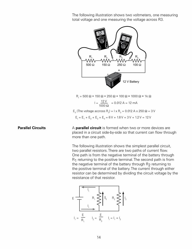
The.following.illustration.shows.two.voltmeters,.one.measuring.total.voltage.and.one.measuring.the.voltage.across.R3.
VOLTS OHMS
AMPSVOLTS OHMS
AMPS
VOLTSOHMSAMPS
VOLTSOHMSAMPS
-+
12 V Battery
R1 R2 R3 R4
250 Ω500 Ω 150 Ω 100 Ω
Rt = 500 Ω + 150 Ω + 250 Ω + 100 Ω = 1000 Ω = 1k Ω
I = 12 V1000 Ω
= 0.012 A = 12 mA
E3 (The voltage accross R3) = I x R3 = 0.012 A x 250 Ω = 3 V
Et = E1 + E2 + E3 + E4 = 6 V + 1.8 V + 3 V + 1.2 V = 12 V
Parallel Circuits. A.parallel circuit is.formed.when.two.or.more.devices.are.placed.in.a.circuit.side-by-side.so.that.current.can.flow.through.more.than.one.path..
The.following.illustration.shows.the.simplest.parallel.circuit,.two.parallel.resistors..There.are.two.paths.of.current.flow..One.path.is.from.the.negative.terminal.of.the.battery.through.R.returning.to.the.positive.terminal..The.second.path.is.from.the.negative.terminal.of.the.battery.through.R2.returning.to.the.positive.terminal.of.the.battery..The.current.through.either.resistor.can.be.determined.by.dividing.the.circuit.voltage.by.the.resistance.of.that.resistor.
It = I1 + I2
R1 R2I1 I2
It
It
E
I1 =E
R1
I2 =E
R2
5
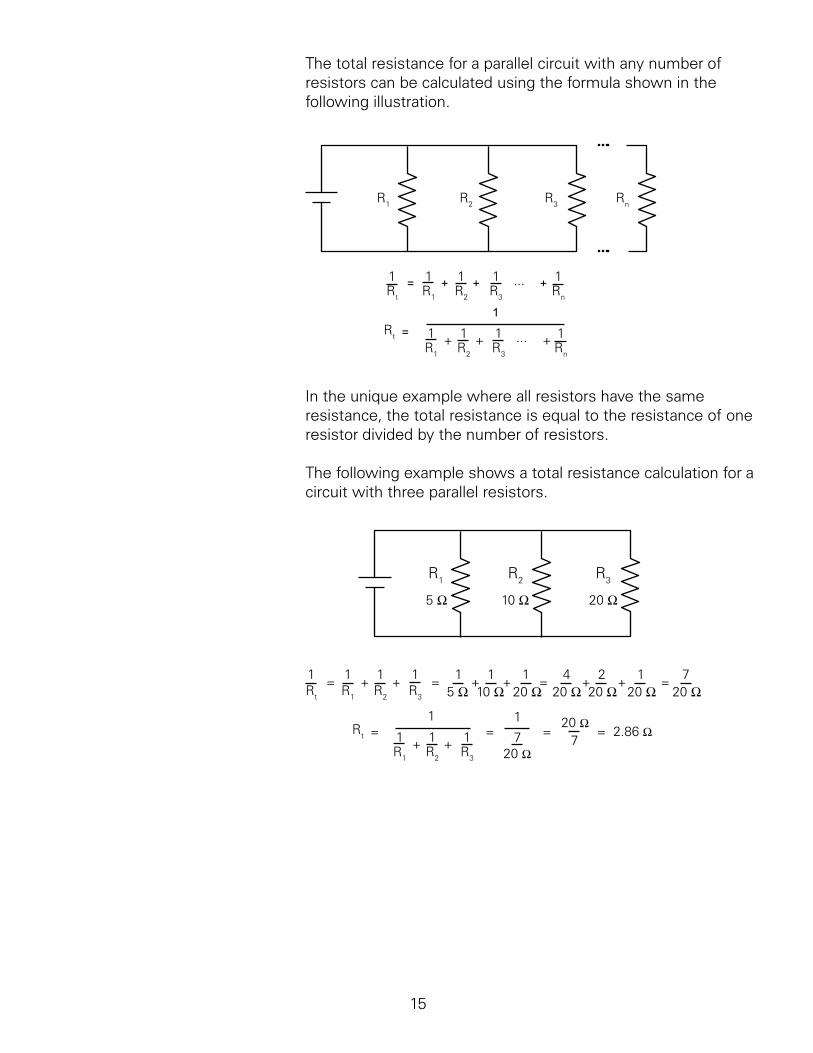
The.total.resistance.for.a.parallel.circuit.with.any.number.of.resistors.can.be.calculated.using.the.formula.shown.in.the.following.illustration.
1Rt R1 R2 R3 Rn
1 1 11= + ++ ...
Rt
R1 R2 R3 Rn
1 1 11+ ++ ...
1
=
R1 R2 R3 Rn
In.the.unique.example.where.all.resistors.have.the.same.resistance,.the.total.resistance.is.equal.to.the.resistance.of.one.resistor.divided.by.the.number.of.resistors.
The.following.example.shows.a.total.resistance.calculation.for.a.circuit.with.three.parallel.resistors.
R1 R2 R3
5 Ω 10 Ω 20 Ω
1Rt R1 R2 R3
1 1 1= + + = 1 1 1+ + = 4 2 1+ +5 Ω 10 Ω 20 Ω 20 Ω 20 Ω 20 Ω
= 720 Ω
Rt
R1 R2 R3
1 1 1+ +
1= =
1
720 Ω
=7
20 Ω= 2.86 Ω
6
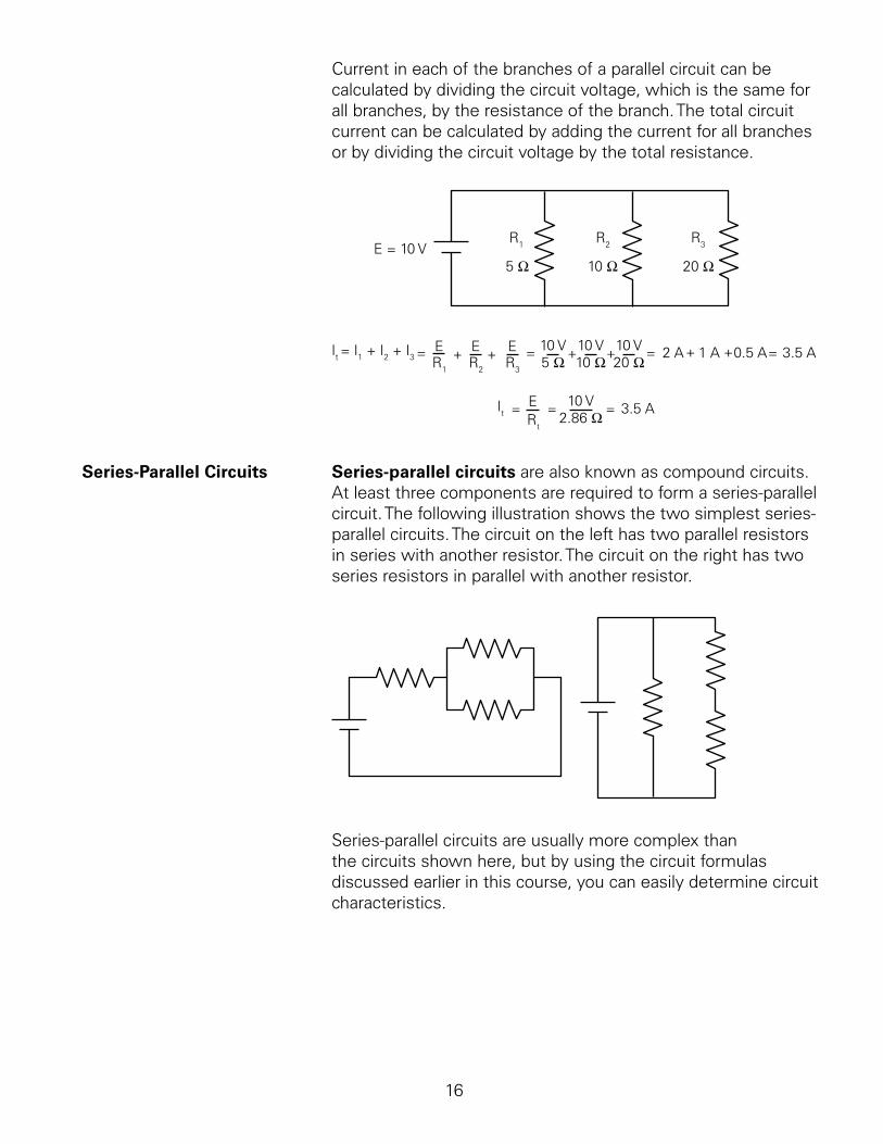
Current.in.each.of.the.branches.of.a.parallel.circuit.can.be.calculated.by.dividing.the.circuit.voltage,.which.is.the.same.for.all.branches,.by.the.resistance.of.the.branch..The.total.circuit.current.can.be.calculated.by.adding.the.current.for.all.branches.or.by.dividing.the.circuit.voltage.by.the.total.resistance.
R1 R2 R3
5 Ω 10 Ω 20 ΩE = 10 V
+ +R1
ER2
ER3
E =It = I1 + I2 + I3 = + +10 V5 Ω 10 Ω
10 V20 Ω10 V = + = +2 A 1 A 0.5 A 3.5 A
Rt
=It E =
2.86 Ω10 V = 3.5 A
Series-Parallel Circuits. Series-parallel circuits.are.also.known.as.compound.circuits..At.least.three.components.are.required.to.form.a.series-parallel.circuit..The.following.illustration.shows.the.two.simplest.series-parallel.circuits..The.circuit.on.the.left.has.two.parallel.resistors.in.series.with.another.resistor..The.circuit.on.the.right.has.two.series.resistors.in.parallel.with.another.resistor.
Series-parallel.circuits.are.usually.more.complex.than.the.circuits.shown.here,.but.by.using.the.circuit.formulas.discussed.earlier.in.this.course,.you.can.easily.determine.circuit.characteristics.
7
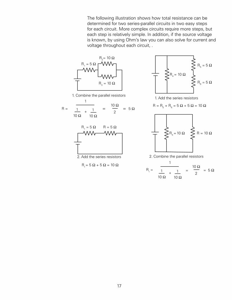
The.following.illustration.shows.how.total.resistance.can.be.determined.for.two.series-parallel.circuits.in.two.easy.steps.for.each.circuit..More.complex.circuits.require.more.steps,.but.each.step.is.relatively.simple..In.addition,.if.the.source.voltage.is.known,.by.using.Ohm’s.law.you.can.also.solve.for.current.and.voltage.throughout.each.circuit,...
R1 = 5 ΩR2= 10 Ω
R3 = 10 Ω
1. Combine the parallel resistors
R = 1
10 Ω1
10 Ω
1
=2
10 Ω= 5 Ω
R1 = 5 Ω R = 5 Ω
2. Add the series resistors
Rt = 5 Ω + 5 Ω = 10 Ω
1. Add the series resistors
R4 = 10 Ω
R5 = 5 Ω
R6 = 5 Ω
R = R5 + R6 = 5 Ω + 5 Ω = 10 Ω
R4 = 10 Ω R = 10 Ω
2. Combine the parallel resistors
Rt = 1
10 Ω1
10 Ω
1
=2
10 Ω= 5 Ω
+
+
8
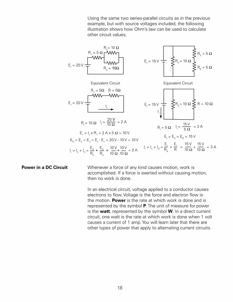
Using.the.same.two.series-parallel.circuits.as.in.the.previous.example,.but.with.source.voltages.included,.the.following.illustration.shows.how.Ohm’s.law.can.be.used.to.calculate.other.circuit.values.
R1 = 5 ΩR2= 10 Ω
R3 = 10ΩEt = 20 V
R1 = 5Ω R = 5Ω
Equivalent Circuit
Et = 20 VIt
Rt = 10 Ω It =20 V10 Ω = 2 A
E1 = It x R1 = 2 A x 5 Ω = 10 V
ER = E2 = E3 = Et - E1 = 20 V - 10 V = 10 V
It = I2 + I3 =ER
R2 R3
ER+ =10 V
+10 V
10 Ω 10 Ω= 2 A
Equivalent Circuit
R4 = 10 Ω
R5 = 5 Ω
R6 = 5 ΩEt = 15 V
R4 = 10 Ω R = 10 ΩEt = 15 V
Rt = 5 Ω It =15 V5 Ω
= 3 A
Et = E4 = ER = 15 V
It = I4 + IR = Et
R4
Et
R+ =
10 Ω15 V
+10 Ω15 V
= 3 A
It
Power in a DC Circuit. Whenever.a.force.of.any.kind.causes.motion,.work.is.accomplished..If.a.force.is.exerted.without.causing.motion,.then.no.work.is.done.
In.an.electrical.circuit,.voltage.applied.to.a.conductor.causes.electrons.to.flow..Voltage.is.the.force.and.electron.flow.is.the.motion..Power.is.the.rate.at.which.work.is.done.and.is.represented.by.the.symbol.P..The.unit.of.measure.for.power.is.the.watt,.represented.by.the.symbol.W..In.a.direct.current.circuit,.one.watt.is.the.rate.at.which.work.is.done.when..volt.causes.a.current.of..amp..You.will.learn.later.that.there.are.other.types.of.power.that.apply.to.alternating.current.circuits.
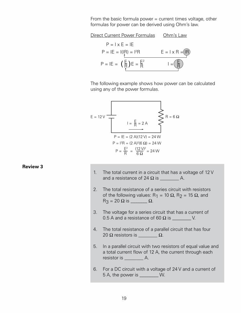
From.the.basic.formula.power.=.current.times.voltage,.other.formulas.for.power.can.be.derived.using.Ohm’s.law.
P = I x E = IE
E = I x R = IRP = IE = I(IR) = I2R
I = ER
Ohm’s LawDirect Current Power Formulas
P = IE = ER( )E = E2
R
The.following.example.shows.how.power.can.be.calculated.using.any.of.the.power.formulas.
R = 6 ΩE = 12 V
I = ER = 2 A
P = IE = (2 A)(12 V) = 24 W
P = I2R = (2 A)2(6 Ω) = 24 W
P = E2
R= (12 V)2
6 Ω= 24 W
Review 3.. The.total.current.in.a.circuit.that.has.a.voltage.of.2.V.
and.a.resistance.of.24.W.is.________.A.
2.. The.total.resistance.of.a.series.circuit.with.resistors.of.the.following.values:.R.=.0.W,.R2.=.5.W,.and.R3.=.20.W.is._______.W.
3.. The.voltage.for.a.series.circuit.that.has.a.current.of.0.5.A.and.a.resistance.of.60.W.is.________.V.
4.. The.total.resistance.of.a.parallel.circuit.that.has.four.20.W.resistors.is.________.W.
5.. In.a.parallel.circuit.with.two.resistors.of.equal.value.and.a.total.current.flow.of.2.A,.the.current.through.each.resistor.is.________.A.
6... For.a.DC.circuit.with.a.voltage.of.24.V.and.a.current.of.5.A,.the.power.is.________.W.
20
Magnetism
The.principles.of.magnetism.are.an.integral.part.of.electricity..In.fact,.magnetism.can.be.used.to.produce.electric.current.and.vice.versa.
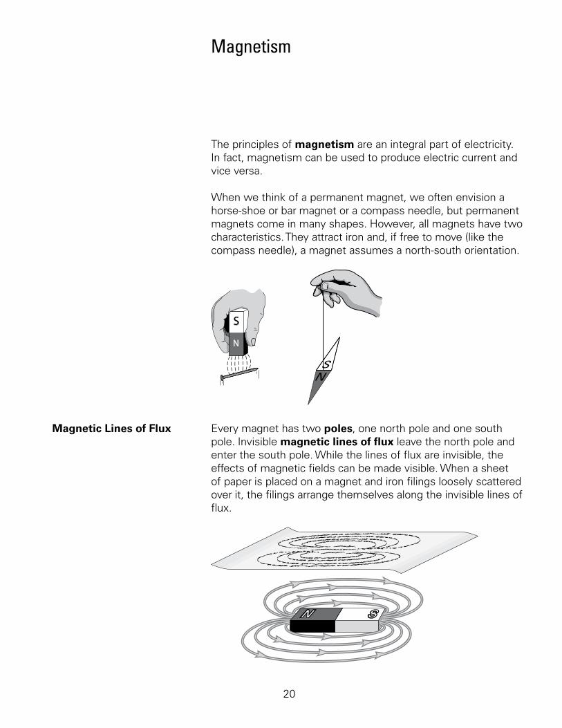
When.we.think.of.a.permanent.magnet,.we.often.envision.a.horse-shoe.or.bar.magnet.or.a.compass.needle,.but.permanent.magnets.come.in.many.shapes..However,.all.magnets.have.two.characteristics..They.attract.iron.and,.if.free.to.move.(like.the.compass.needle),.a.magnet.assumes.a.north-south.orientation..
N
S
Magnetic Lines of Flux. Every.magnet.has.two.poles,.one.north.pole.and.one.south.pole..Invisible.magnetic lines of flux.leave.the.north.pole.and.enter.the.south.pole..While.the.lines.of.flux.are.invisible,.the.effects.of.magnetic.fields.can.be.made.visible..When.a.sheet.of.paper.is.placed.on.a.magnet.and.iron.filings.loosely.scattered.over.it,.the.filings.arrange.themselves.along.the.invisible.lines.of.flux..
2
The.density.of.these.lines.of.flux.is.greatest.inside.the.magnet.and.where.the.lines.of.flux.enter.and.leave.the.magnet..The.greater.the.density.of.the.lines.of.flux,.the.stronger.the.magnetic.field.
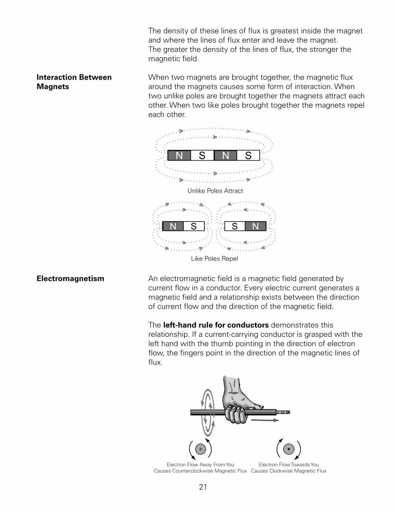
Interaction Between. When.two.magnets.are.brought.together,.the.magnetic.flux.Magnets. around.the.magnets.causes.some.form.of.interaction..When.
two.unlike.poles.are.brought.together.the.magnets.attract.each.other..When.two.like.poles.brought.together.the.magnets.repel.each.other.
Unlike Poles Attract
Like Poles Repel
Electromagnetism. An.electromagnetic.field.is.a.magnetic.field.generated.by.current.flow.in.a.conductor..Every.electric.current.generates.a.magnetic.field.and.a.relationship.exists.between.the.direction.of.current.flow.and.the.direction.of.the.magnetic.field..
The.left-hand rule for conductors.demonstrates.this.relationship..If.a.current-carrying.conductor.is.grasped.with.the.left.hand.with.the.thumb.pointing.in.the.direction.of.electron.flow,.the.fingers.point.in.the.direction.of.the.magnetic.lines.of.flux.
Electron Flow Away From YouCauses Counterclockwise Magnetic Flux
Electron Flow Towards YouCauses Clockwise Magnetic Flux
22
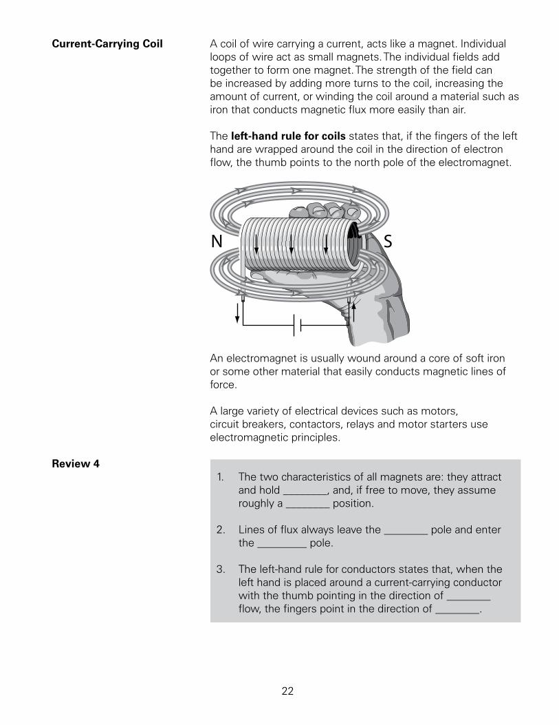
Current-Carrying Coil. A.coil.of.wire.carrying.a.current,.acts.like.a.magnet..Individual.loops.of.wire.act.as.small.magnets..The.individual.fields.add.together.to.form.one.magnet..The.strength.of.the.field.can.be.increased.by.adding.more.turns.to.the.coil,.increasing.the.amount.of.current,.or.winding.the.coil.around.a.material.such.as.iron.that.conducts.magnetic.flux.more.easily.than.air..
The.left-hand rule for coils.states.that,.if.the.fingers.of.the.left.hand.are.wrapped.around.the.coil.in.the.direction.of.electron.flow,.the.thumb.points.to.the.north.pole.of.the.electromagnet.
An.electromagnet.is.usually.wound.around.a.core.of.soft.iron.or.some.other.material.that.easily.conducts.magnetic.lines.of.force..
A.large.variety.of.electrical.devices.such.as.motors,.circuit.breakers,.contactors,.relays.and.motor.starters.use.electromagnetic.principles.
Review 4... The.two.characteristics.of.all.magnets.are:.they.attract.
and.hold.________,.and,.if.free.to.move,.they.assume.roughly.a.________.position.
2.. Lines.of.flux.always.leave.the.________.pole.and.enter.the._________.pole.
3.. The.left-hand.rule.for.conductors.states.that,.when.the.left.hand.is.placed.around.a.current-carrying.conductor.with.the.thumb.pointing.in.the.direction.of.________.flow,.the.fingers.point.in.the.direction.of.________.
23
Alternating Current
The.supply.of.current.for.electrical.devices.may.come.from.a.direct.current.(DC).source.or.an.alternating current (AC).source..In.a.direct.current.circuit,.electrons.flow.continuously.in.one.direction.from.the.source.of.power.through.a.conductor.to.a.load.and.back.to.the.source.of.power..Voltage.polarity.for.a.direct.current.source.remains.constant..DC.power.sources.include.batteries.and.DC.generators..
By.contrast,.an.AC.generator.makes.electrons.flow.first.in.one.direction.then.in.another..In.fact,.an.AC.generator.reverses.its.terminal.polarities.many.times.a.second,.causing.current.to.change.direction.with.each.reversal.
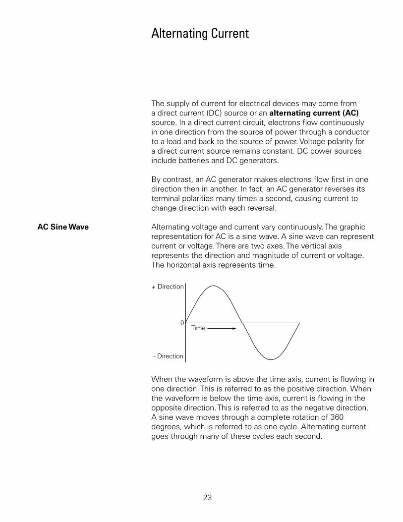
AC Sine Wave. Alternating.voltage.and.current.vary.continuously..The.graphic.representation.for.AC.is.a.sine.wave..A.sine.wave.can.represent.current.or.voltage..There.are.two.axes..The.vertical.axis.represents.the.direction.and.magnitude.of.current.or.voltage..The.horizontal.axis.represents.time.
+ Direction
- Direction
0Time
When.the.waveform.is.above.the.time.axis,.current.is.flowing.in.one.direction..This.is.referred.to.as.the.positive.direction..When.the.waveform.is.below.the.time.axis,.current.is.flowing.in.the.opposite.direction..This.is.referred.to.as.the.negative.direction..A.sine.wave.moves.through.a.complete.rotation.of.360.degrees,.which.is.referred.to.as.one.cycle..Alternating.current.goes.through.many.of.these.cycles.each.second..
24
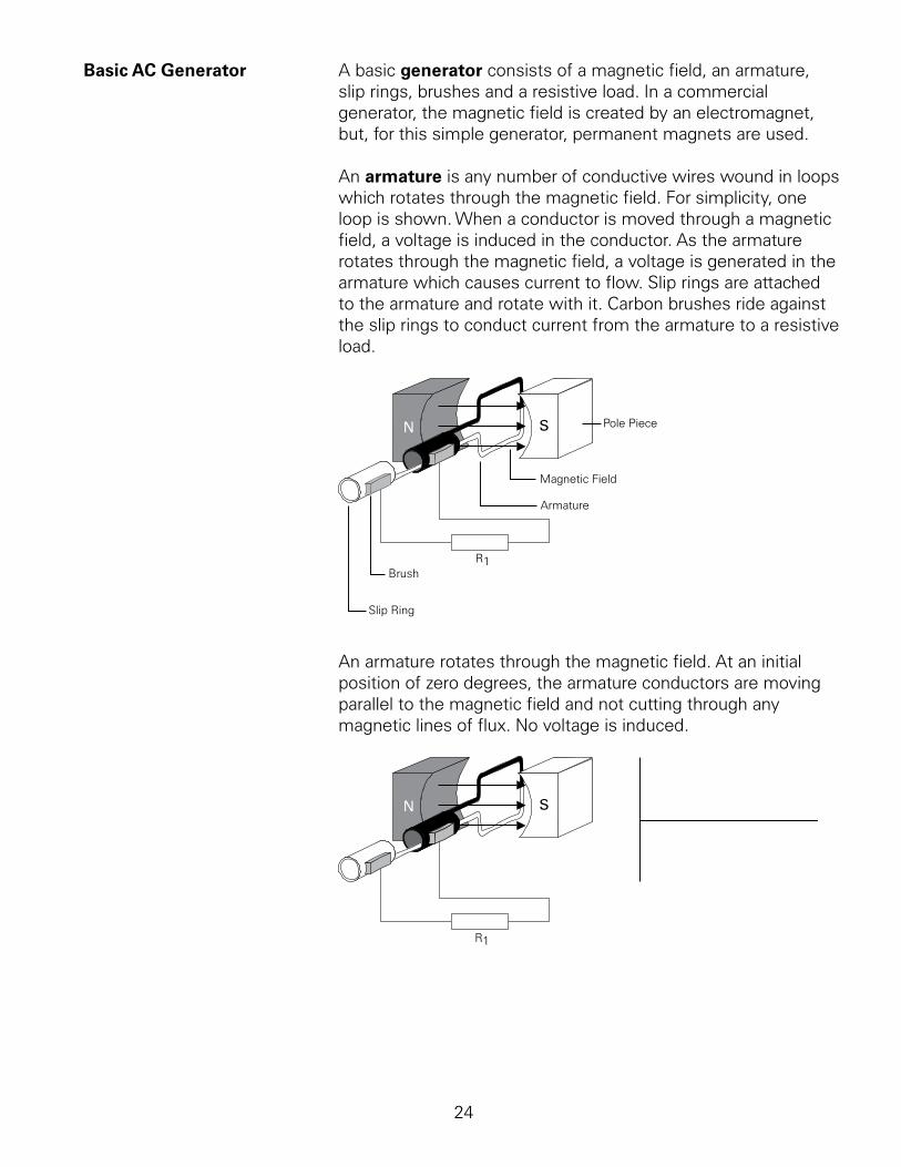
Basic AC Generator. A.basic.generator.consists.of.a.magnetic.field,.an.armature,.slip.rings,.brushes.and.a.resistive.load..In.a.commercial.generator,.the.magnetic.field.is.created.by.an.electromagnet,.but,.for.this.simple.generator,.permanent.magnets.are.used.
An.armature.is.any.number.of.conductive.wires.wound.in.loops.which.rotates.through.the.magnetic.field..For.simplicity,.one.loop.is.shown..When.a.conductor.is.moved.through.a.magnetic.field,.a.voltage.is.induced.in.the.conductor..As.the.armature.rotates.through.the.magnetic.field,.a.voltage.is.generated.in.the.armature.which.causes.current.to.flow..Slip.rings.are.attached.to.the.armature.and.rotate.with.it..Carbon.brushes.ride.against.the.slip.rings.to.conduct.current.from.the.armature.to.a.resistive.load.
Pole Piece
Magnetic Field
Armature
Brush
Slip Ring
R1
An.armature.rotates.through.the.magnetic.field..At.an.initial.position.of.zero.degrees,.the.armature.conductors.are.moving.parallel.to.the.magnetic.field.and.not.cutting.through.any.magnetic.lines.of.flux..No.voltage.is.induced..
R1
25
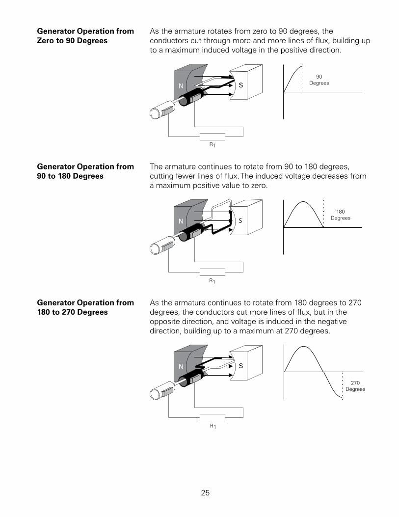
Generator Operation from. As.the.armature.rotates.from.zero.to.0.degrees,.the.Zero to 90 Degrees. conductors.cut.through.more.and.more.lines.of.flux,.building.up.
to.a.maximum.induced.voltage.in.the.positive.direction.
R1
90Degrees
Generator Operation from. The.armature.continues.to.rotate.from.0.to.80.degrees,.90 to 180 Degrees. cutting.fewer.lines.of.flux..The.induced.voltage.decreases.from.
a.maximum.positive.value.to.zero.
S
R1
180Degrees
Generator Operation from. As.the.armature.continues.to.rotate.from.80.degrees.to.270.180 to 270 Degrees. degrees,.the.conductors.cut.more.lines.of.flux,.but.in.the.
opposite.direction,.and.voltage.is.induced.in.the.negative.direction,.building.up.to.a.maximum.at.270.degrees.
R1
270Degrees

26
Generator Operation from. As.the.armature.continues.to.rotate.from.270.to.360.degrees,.270 to 360 Degrees. induced.voltage.decreases.from.a.maximum.negative.value.
to.zero..This.completes.one.cycle..The.armature.continues.to.rotate.at.a.constant.speed.causing.the.cycle.to.repeat.as.long.as.the.armature.rotates.
S
R1
One Revolution
360Degrees
Four-Pole AC Generator. An.AC.generator.produces.one.cycle.per.revolution.for.each.pair.of.poles..An.increase.in.the.number.of.poles,.causes.an.increase.in.the.number.of.cycles.completed.in.a.revolution..A.two-pole.generator.completes.one.cycle.per.revolution.and.a.four-pole.generator.completes.two.cycles.per.revolution..
R1
One Revolution
Frequency. The.number.of.cycles.per.second.of.voltage.induced.in.the.armature.is.the.frequency.of.the.generator..If.a.two-pole.generator.armature.rotates.at.a.speed.of.60.revolutions.per.second,.the.generated.voltage.have.a.frequency.of.60.cycles.per.second..The.recognized.unit.for.frequency.is.hertz, abbreviated.Hz...Hz.is.equal.to..cycle.per.second.
27
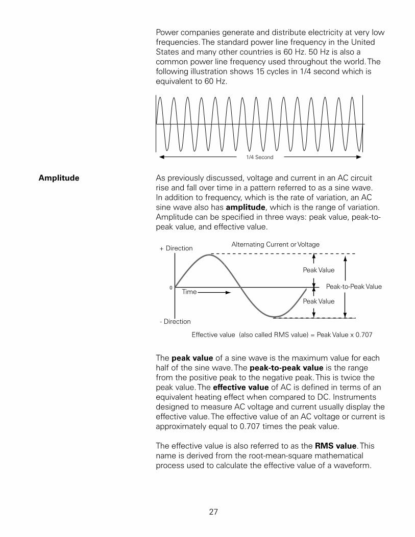
Power.companies.generate.and.distribute.electricity.at.very.low.frequencies..The.standard.power.line.frequency.in.the.United.States.and.many.other.countries.is.60.Hz..50.Hz.is.also.a.common.power.line.frequency.used.throughout.the.world..The.following.illustration.shows.5.cycles.in./4.second.which.is.equivalent.to.60.Hz.
1/4 Second
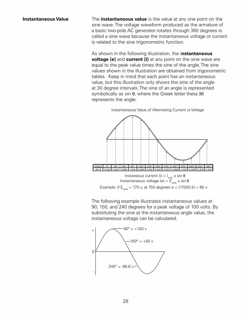
Amplitude. As.previously.discussed,.voltage.and.current.in.an.AC.circuit.rise.and.fall.over.time.in.a.pattern.referred.to.as.a.sine.wave..In.addition.to.frequency,.which.is.the.rate.of.variation,.an.AC.sine.wave.also.has.amplitude,.which.is.the.range.of.variation..Amplitude.can.be.specified.in.three.ways:.peak.value,.peak-to-peak.value,.and.effective.value.
Alternating Current or Voltage+ Direction
- Direction
0Time
Peak Value
Peak Value
Peak-to-Peak Value
Effective value (also called RMS value) = Peak Value x 0.707
The.peak value.of.a.sine.wave.is.the.maximum.value.for.each.half.of.the.sine.wave..The peak-to-peak value.is.the.range.from.the.positive.peak.to.the.negative.peak..This.is.twice.the.peak.value..The.effective value.of.AC.is.defined.in.terms.of.an.equivalent.heating.effect.when.compared.to.DC..Instruments.designed.to.measure.AC.voltage.and.current.usually.display.the.effective.value..The.effective.value.of.an.AC.voltage.or.current.is.approximately.equal.to.0.707.times.the.peak.value.
The.effective.value.is.also.referred.to.as.the.RMS value..This.name.is.derived.from.the.root-mean-square.mathematical.process.used.to.calculate.the.effective.value.of.a.waveform.
28
Instantaneous Value. The.instantaneous value.is.the.value.at.any.one.point.on.the.sine.wave..The.voltage.waveform.produced.as.the.armature.of.a.basic.two-pole.AC.generator.rotates.through.360.degrees.is.called.a.sine.wave.because.the.instantaneous.voltage.or.current.is.related.to.the.sine.trigonometric.function..
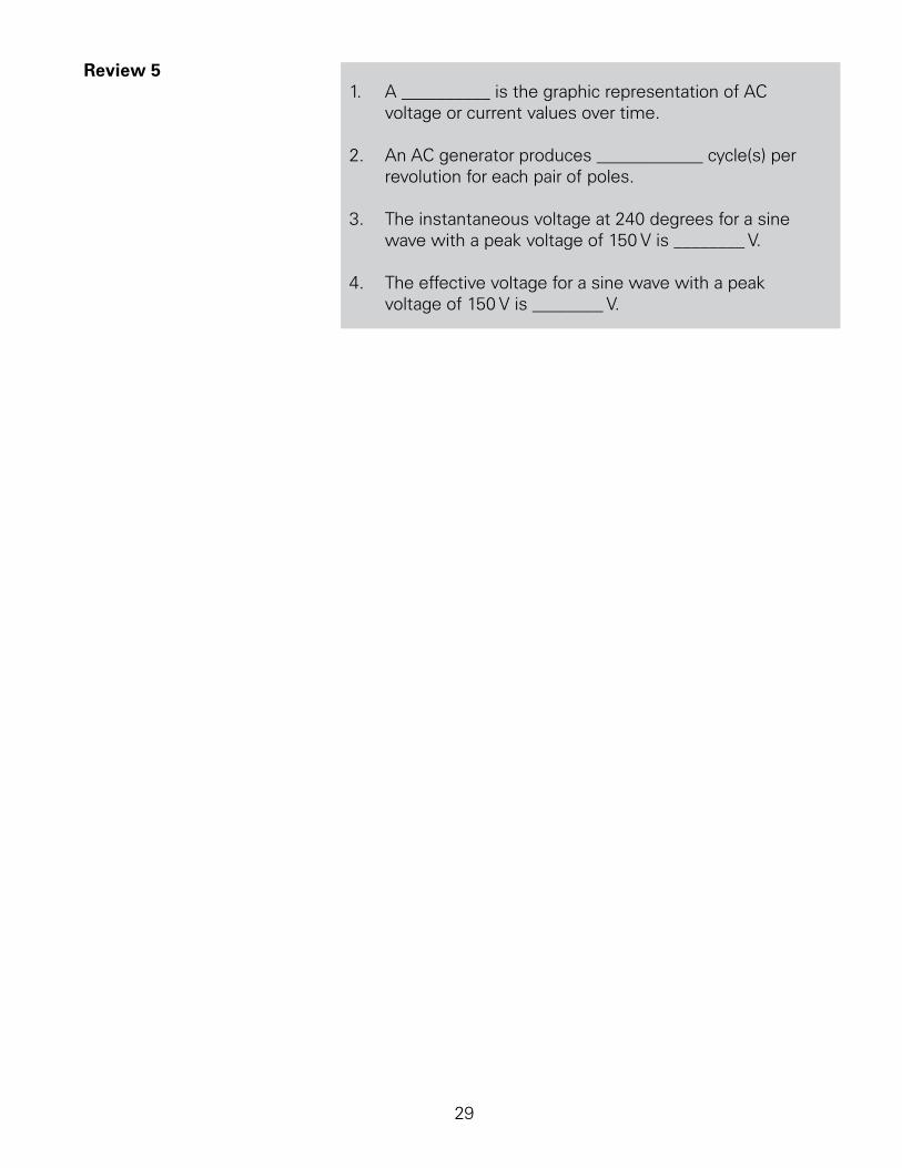
As.shown.in.the.following.illustration,.the.instantaneous voltage (e).and.current (i).at.any.point.on.the.sine.wave.are.equal.to.the.peak.value.times.the.sine.of.the.angle..The.sine.values.shown.in.the.illustration.are.obtained.from.trigonometric.tables...Keep.in.mind.that.each.point.has.an.instantaneous.value,.but.this.illustration.only.shows.the.sine.of.the.angle.at.30.degree.intervals..The.sine.of.an.angle.is.represented.symbolically.as.sin.q,.where.the.Greek.letter.theta.(q).represents.the.angle.
Instantaneous Value of Alternating Current or Voltage
Instantaneous voltage (e) = Epeak x sin θ
A ng le 0° 30° 60° 90° 120° 150° 180° 210° 240° 270° 300° 330° 360°S in θ 0 .000 0 .500 0 .866 1 .000 0 .866 0 .500 0 .000 -0 .500 -0 .866 -1 .000 -0 .866 -0 .500 0 .000
Instaneous current (i) = Ipeak x sin θ
Example: if Epeak = 170 v, at 150 degrees e = (170)(0.5) = 85 v
The.following.example.illustrates.instantaneous.values.at.0,.50,.and.240.degrees.for.a.peak.voltage.of.00.volts..By.substituting.the.sine.at.the.instantaneous.angle.value,.the.instantaneous.voltage.can.be.calculated.
90° = +100 v
150° = +50 v
240° = -86.6 v
+
0
-
2
Review 5 .. A.__________.is.the.graphic.representation.of.AC.
voltage.or.current.values.over.time.
2.. An.AC.generator.produces.____________.cycle(s).per.revolution.for.each.pair.of.poles.
3.. The.instantaneous.voltage.at.240.degrees.for.a.sine.wave.with.a.peak.voltage.of.50.V.is.________.V.
4.. The.effective.voltage.for.a.sine.wave.with.a.peak.voltage.of.50.V.is.________.V.
30
Inductance and Capacitance
Inductance. The.circuits.studied.to.this.point.have.been.resistive..Resistance.and.voltage.are.not.the.only.circuit.properties.that.effect.current.flow,.however..Inductance.is.the.property.of.an.electric.circuit.that.opposes.any.change.in.electric.current..Resistance.opposes.current.flow,.inductance.opposes.changes.in.current.flow..Inductance.is.designated.by.the.letter.L..The.unit.of.measurement.for.inductance.is.the.henry (h);.however,.because.the.henry.is.a.relatively.large.unit,.inductance.is.often.rated.in.millihenries.or.microhenries.
Unit Symbol Equivalent Measuremillihenry mh 1 mh = 0.001 h
microhenry µh 1 µh = 0.000001 h
Current.flow.produces.a.magnetic.field.in.a.conductor..The.amount.of.current.determines.the.strength.of.the.magnetic.field..As.current.flow.increases,.field.strength.increases,.and.as.current.flow.decreases,.field.strength.decreases.
Any.change.in.current.causes.a.corresponding.change.in.the.magnetic.field.surrounding.the.conductor..Current.is.constant.for.a.regulated.DC.source,.except.when.the.circuit.is.turned.on.and.off,.or.when.there.is.a.load.change..However,.alternating.current.is.constantly.changing,.and.inductance.is.continually.opposing.the.change..A.change.in.the.magnetic.field.surrounding.the.conductor.induces.a.voltage.in.the.conductor..This.self-induced.voltage.opposes.the.change.in.current..This.is.known.as.counter emf..
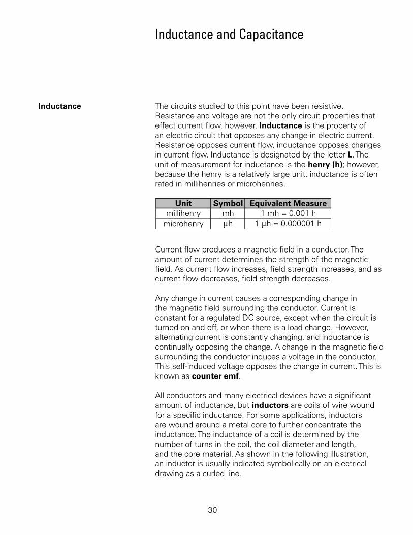
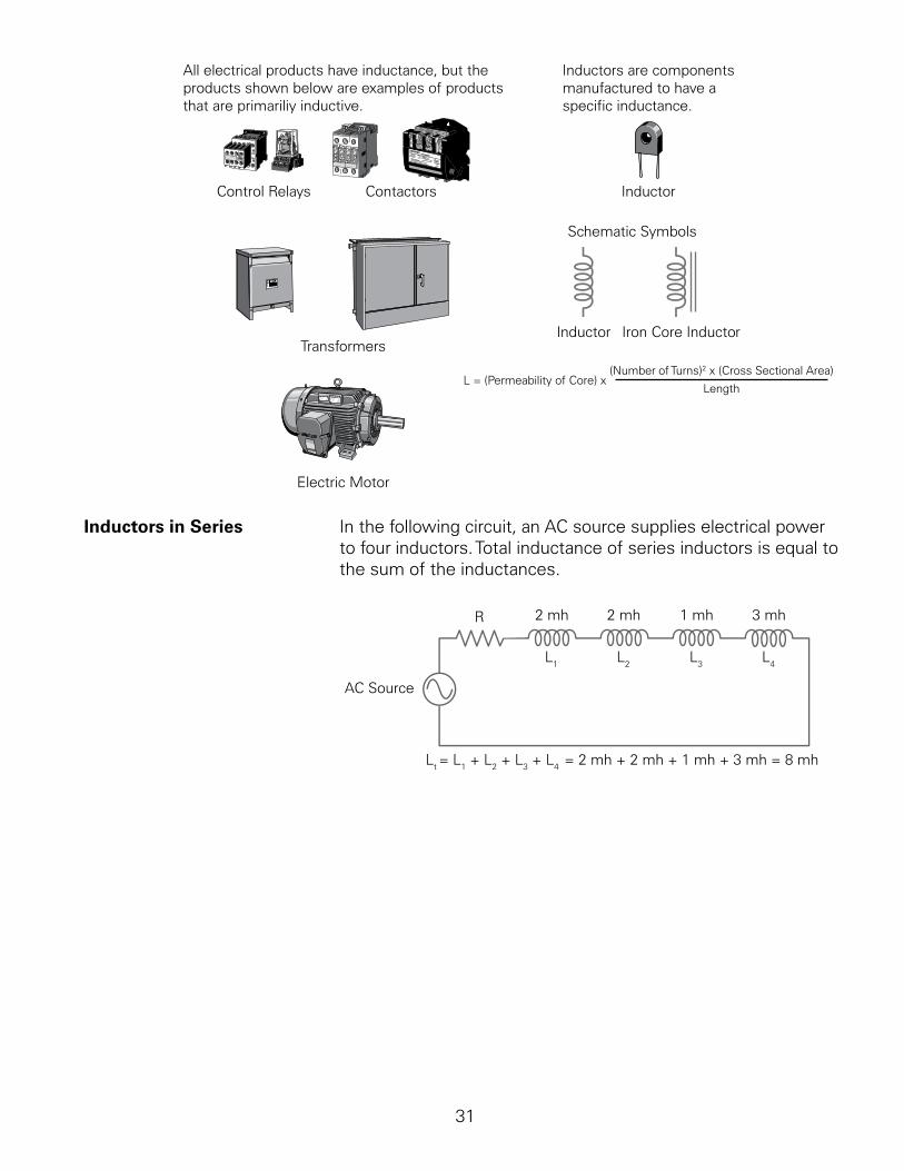
All.conductors.and.many.electrical.devices.have.a.significant.amount.of.inductance,.but.inductors.are.coils.of.wire.wound.for.a.specific.inductance..For.some.applications,.inductors.are.wound.around.a.metal.core.to.further.concentrate.the.inductance..The.inductance.of.a.coil.is.determined.by.the.number.of.turns.in.the.coil,.the.coil.diameter.and.length,.and.the.core.material..As.shown.in.the.following.illustration,.an.inductor.is.usually.indicated.symbolically.on.an.electrical.drawing.as.a.curled.line.
3
All electrical products have inductance, but theproducts shown below are examples of productsthat are primariliy inductive.
Control Relays Contactors
Transformers
Electric Motor
Inductors are componentsmanufactured to have a specific inductance.
Schematic Symbols
Inductor Iron Core Inductor
L = (Permeability of Core) x (Number of Turns)2 x (Cross Sectional Area)
Length
Inductor
Inductors in Series. In.the.following.circuit,.an.AC.source.supplies.electrical.power.to.four.inductors..Total.inductance.of.series.inductors.is.equal.to.the.sum.of.the.inductances.
AC Source
R 2 mh 2 mh 1 mh 3 mh
L1 L2 L3 L4
Lt = L1 + L2 + L3 + L4 = 2 mh + 2 mh + 1 mh + 3 mh = 8 mh

32
Inductors in Parallel. The.total.inductance.of.inductors.in.parallel.is.calculated.using.a.formula.similar.to.the.formula.for.resistance.of.parallel.resistors..The.following.illustration.shows.the.calculation.for.a.circuit.with.three.parallel.inductors.
AC Source
R
L1 L2 L3
5 mh 10 mh 20 mh
Lt L1 L2 L3
1 111= + + =
5 mh 10 mh 20 mh1 11
+ +20 mh
2 14+ +=
20 mh20 mh=
20 mh7
Lt
L1L2
L3
1 11+ +
=
1=
1
20 mh7 20 mh
7= = 2.86 mh
Capacitance and Capacitors. Capacitance.is.a.measure.of.a.circuit’s.ability.to.store.an.electrical.charge..A.device.manufactured.to.have.a.specific.amount.of.capacitance.is.called.a.capacitor..A.capacitor.is.made.up.of.a.pair.of.conductive.plates.separated.by.a.thin.layer.of.insulating.material..Another.name.for.the.insulating.material.is.dielectric.material..A.capacitor.is.usually.indicated.symbolically.on.an.electrical.drawing.by.a.combination.of.a.straight.line.with.a.curved.line.or.two.straight.lines.
Negative PlateDielectric Material
Positive Plate
Direct current cannot flow througha capacitor unless it is defective
53JZ 22UF
Schematic Symbols
Capacitors are components manufacturedto have a specific capacitance.
When.a.voltage.is.applied.to.the.plates.of.a.capacitor,.electrons.are.forced.onto.one.plate.and.pulled.from.the.other..This.charges.the.capacitor..Direct.current.cannot.flow.through.the.dielectric.material.because.it.is.an.insulator;.however,.the.electric.field.created.when.the.capacitor.is.charged.is.felt.through.the.dielectric..Capacitors.are.rated.for.the.amount.of.charge.they.can.hold..
33
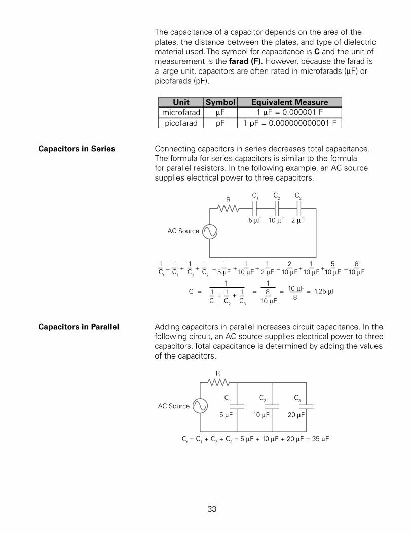
The.capacitance.of.a.capacitor.depends.on.the.area.of.the.plates,.the.distance.between.the.plates,.and.type.of.dielectric.material.used..The.symbol.for.capacitance.is.C.and.the.unit.of.measurement.is.the.farad (F)..However,.because.the.farad.is.a.large.unit,.capacitors.are.often.rated.in.microfarads.(mF).or.picofarads.(pF).
Unit Symbol Equivalent Measuremicrofarad µF 1 µF = 0.000001 Fpicofarad pF 1 pF = 0.000000000001 F
Capacitors in Series Connecting.capacitors.in.series.decreases.total.capacitance...The.formula.for.series.capacitors.is.similar.to.the.formula.for.parallel.resistors..In.the.following.example,.an.AC.source.supplies.electrical.power.to.three.capacitors..
AC Source
RC1 C2 C3
5 µF 10 µF 2 µF
Ct C1 C3 C2
1 111= + + =
5 µF 10 µF 2 µF1 11
+ +10 µF
1 52+ +=
10 µF10 µF=
10 µF8
1 1Ct
C1 C2 C3
1 11 + += =
10 µF8 10 µF
8 = = 1.25 µF
Capacitors in Parallel. Adding.capacitors.in.parallel.increases.circuit.capacitance..In.the.following.circuit,.an.AC.source.supplies.electrical.power.to.three.capacitors..Total.capacitance.is.determined.by.adding.the.values.of.the.capacitors.
C1 C2 C3
5 µF 10 µF 20 µFAC Source
R
Ct = C1 + C2 + C3 = 5 µF + 10 µF + 20 µF = 35 µF

34
Review 6.. The.total.inductance.for.this.circuit.is.________.mh..
.
4 mh 2 mh 3 mh 1 mh
L1 L2 L3 L4
2.. The.total.inductance.for.this.circuit.is.________.mh..
.
L1 L2 L3
5 mh 10 mh 10 mh
3.. The.total.capacitance.for.this.circuit.is.________.mF..
.
C1 C2 C35 µF 10 µF10 µF
4.. The.total.capacitance.for.this.circuit.is.________.mF..
.
C1 C2 C3
5 µF 10 µF 10 µF
35
Reactance and Impedance
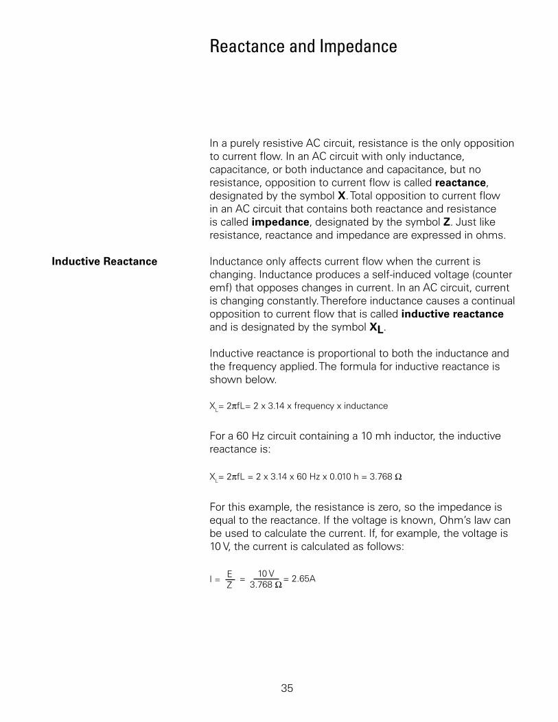
In.a.purely.resistive.AC.circuit,.resistance.is.the.only.opposition.to.current.flow..In.an.AC.circuit.with.only.inductance,.capacitance,.or.both.inductance.and.capacitance,.but.no.resistance,.opposition.to.current.flow.is.called.reactance,.designated.by.the.symbol.X..Total.opposition.to.current.flow.in.an.AC.circuit.that.contains.both.reactance.and.resistance.is.called.impedance,.designated.by.the.symbol.Z..Just.like.resistance,.reactance.and.impedance.are.expressed.in.ohms.
Inductive Reactance. Inductance.only.affects.current.flow.when.the.current.is.changing..Inductance.produces.a.self-induced.voltage.(counter.emf).that.opposes.changes.in.current..In.an.AC.circuit,.current.is.changing.constantly..Therefore.inductance.causes.a.continual.opposition.to.current.flow.that.is.called.inductive reactance.and.is.designated.by.the.symbol.XL..
Inductive.reactance.is.proportional.to.both.the.inductance.and.the.frequency.applied..The.formula.for.inductive.reactance.is.shown.below.
XL= 2πfL= 2 x 3.14 x frequency x inductance
For.a.60.Hz.circuit.containing.a.0.mh.inductor,.the.inductive.reactance.is:
XL= 2πfL = 2 x 3.14 x 60 Hz x 0.010 h = 3.768 Ω
For.this.example,.the.resistance.is.zero,.so.the.impedance.is.equal.to.the.reactance..If.the.voltage.is.known,.Ohm’s.law.can.be.used.to.calculate.the.current..If,.for.example,.the.voltage.is.0.V,.the.current.is.calculated.as.follows:
I = EZ
= 2.65A= 10 V3.768 Ω
36
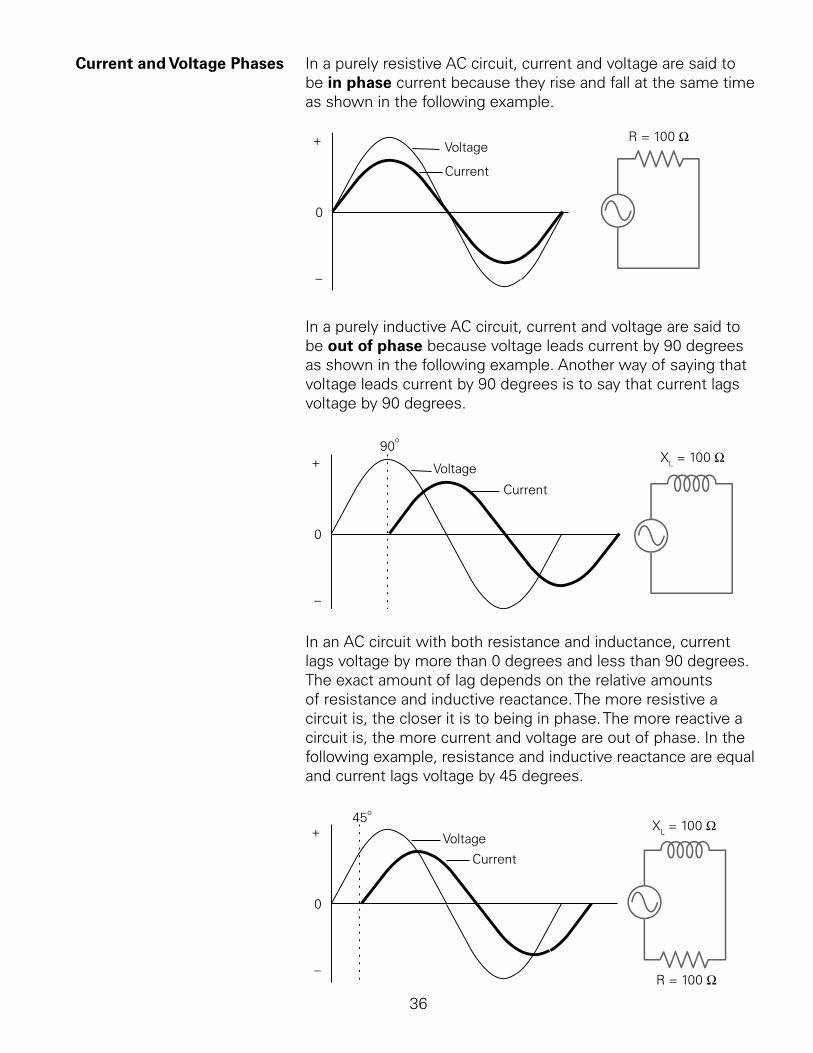
Current and Voltage Phases. In.a.purely.resistive.AC.circuit,.current.and.voltage.are.said.to.be.in phase.current.because.they.rise.and.fall.at.the.same.time.as.shown.in.the.following.example.
+
0
_
Voltage
Current
R = 100 Ω
In.a.purely.inductive.AC.circuit,.current.and.voltage.are.said.to.be.out of phase.because.voltage.leads.current.by.0.degrees.as.shown.in.the.following.example..Another.way.of.saying.that.voltage.leads.current.by.0.degrees.is.to.say.that.current.lags.voltage.by.0.degrees.
+
0
_
90o
Voltage
Current
XL = 100 Ω
In.an.AC.circuit.with.both.resistance.and.inductance,.current.lags.voltage.by.more.than.0.degrees.and.less.than.0.degrees..The.exact.amount.of.lag.depends.on.the.relative.amounts.of.resistance.and.inductive.reactance..The.more.resistive.a.circuit.is,.the.closer.it.is.to.being.in.phase..The.more.reactive.a.circuit.is,.the.more.current.and.voltage.are.out.of.phase..In.the.following.example,.resistance.and.inductive.reactance.are.equal.and.current.lags.voltage.by.45.degrees.
+
0
_
45o
Voltage
Current
R = 100 Ω
XL = 100 Ω
37
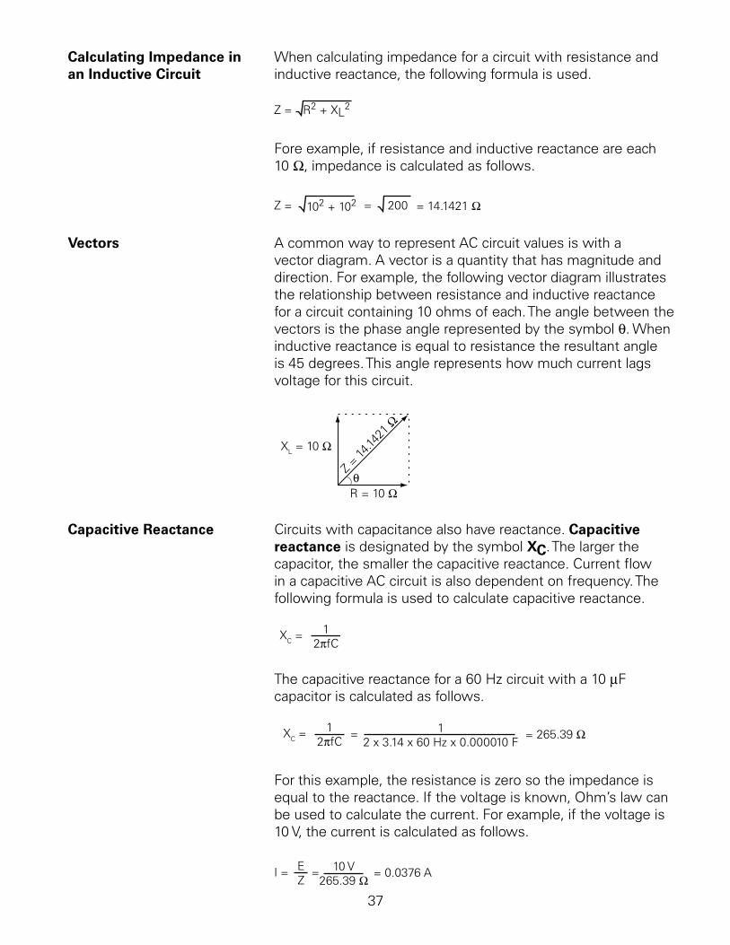
Calculating Impedance in. When.calculating.impedance.for.a.circuit.with.resistance.and.an Inductive Circuit. inductive.reactance,.the.following.formula.is.used.
Z = R2 + XL2
Fore.example,.if.resistance.and.inductive.reactance.are.each.0.W,.impedance.is.calculated.as.follows.
Z = 102 + 102 = = 14.1421 Ω 200
Vectors. A.common.way.to.represent.AC.circuit.values.is.with.a.vector.diagram..A.vector.is.a.quantity.that.has.magnitude.and.direction..For.example,.the.following.vector.diagram.illustrates.the.relationship.between.resistance.and.inductive.reactance.for.a.circuit.containing.0.ohms.of.each..The.angle.between.the.vectors.is.the.phase.angle.represented.by.the.symbol.q..When.inductive.reactance.is.equal.to.resistance.the.resultant.angle.is.45.degrees..This.angle.represents.how.much.current.lags.voltage.for.this.circuit.
θ
XL = 10 Ω
R = 10 Ω
Z = 14
.1421
Ω
Capacitive Reactance. Circuits.with.capacitance.also.have.reactance..Capacitive reactance.is.designated.by.the.symbol.XC..The.larger.the.capacitor,.the.smaller.the.capacitive.reactance..Current.flow.in.a.capacitive.AC.circuit.is.also.dependent.on.frequency..The.following.formula.is.used.to.calculate.capacitive.reactance.
XC = 1 2πfC
The.capacitive.reactance.for.a.60.Hz.circuit.with.a.0.mF.capacitor.is.calculated.as.follows.
XC = 12πfC
= 12 x 3.14 x 60 Hz x 0.000010 F
= 265.39 Ω
For.this.example,.the.resistance.is.zero.so.the.impedance.is.equal.to.the.reactance..If.the.voltage.is.known,.Ohm’s.law.can.be.used.to.calculate.the.current..For.example,.if.the.voltage.is.0.V,.the.current.is.calculated.as.follows.
= 0.0376 A I = E Z
= 10 V265.39 Ω
38
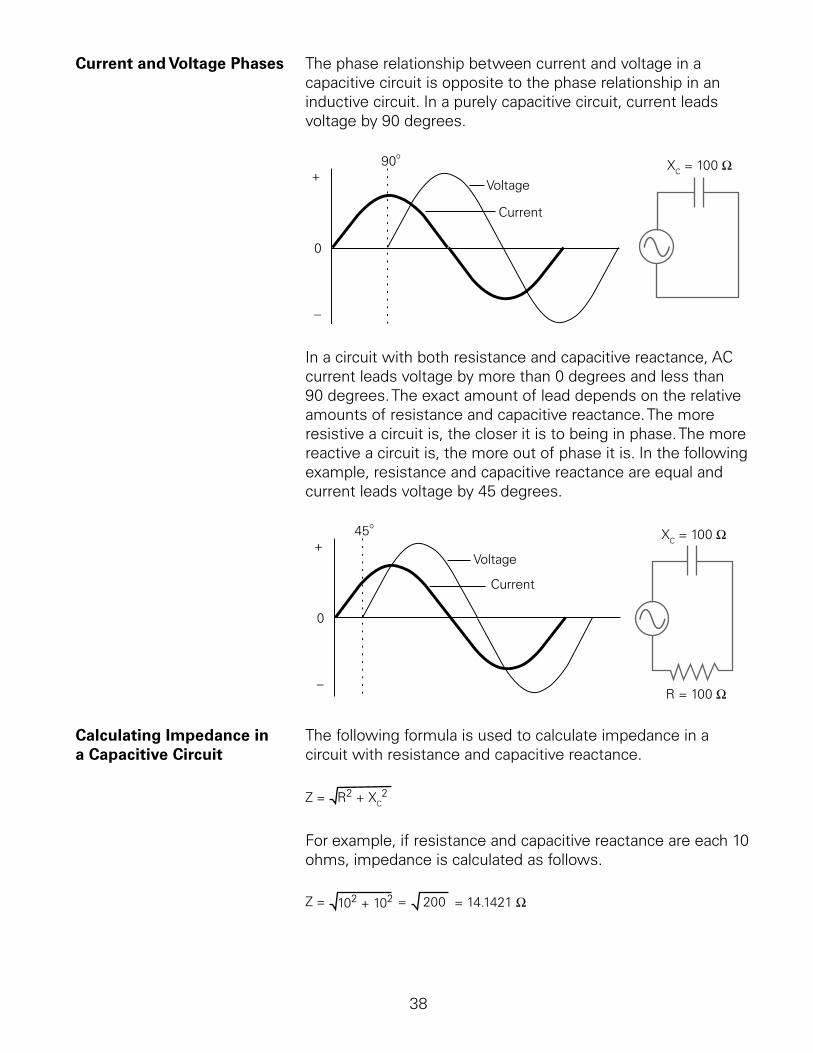
Current and Voltage Phases The.phase.relationship.between.current.and.voltage.in.a.capacitive.circuit.is.opposite.to.the.phase.relationship.in.an.inductive.circuit..In.a.purely.capacitive.circuit,.current.leads.voltage.by.0.degrees.
+
0
_
90o
Voltage
Current
XC = 100 Ω
In.a.circuit.with.both.resistance.and.capacitive.reactance,.AC.current.leads.voltage.by.more.than.0.degrees.and.less.than.0.degrees..The.exact.amount.of.lead.depends.on.the.relative.amounts.of.resistance.and.capacitive.reactance..The.more.resistive.a.circuit.is,.the.closer.it.is.to.being.in.phase..The.more.reactive.a.circuit.is,.the.more.out.of.phase.it.is..In.the.following.example,.resistance.and.capacitive.reactance.are.equal.and.current.leads.voltage.by.45.degrees.
+
0
_
45o
Voltage
Current
R = 100 Ω
XC = 100 Ω
Calculating Impedance in. The.following.formula.is.used.to.calculate.impedance.in.a.a Capacitive Circuit. circuit.with.resistance.and.capacitive.reactance.
Z = R2 + XC2
For.example,.if.resistance.and.capacitive.reactance.are.each.0.ohms,.impedance.is.calculated.as.follows.
Z = 102 + 102 = = 14.1421 Ω 200
3
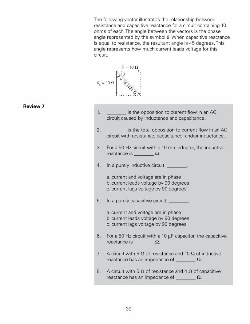
The.following.vector.illustrates.the.relationship.between.resistance.and.capacitive.reactance.for.a.circuit.containing.0.ohms.of.each..The.angle.between.the.vectors.is.the.phase.angle.represented.by.the.symbol.q..When.capacitive.reactance.is.equal.to.resistance,.the.resultant.angle.is.45.degrees..This.angle.represents.how.much.current.leads.voltage.for.this.circuit.
θ
XC = 10 Ω
R = 10 Ω
Z = 14.1421 Ω
Review 7.. ________.is.the.opposition.to.current.flow.in.an.AC.
circuit.caused.by.inductance.and.capacitance.
2.. ________.is.the.total.opposition.to.current.flow.in.an.AC.circuit.with.resistance,.capacitance,.and/or.inductance.
3.. For.a.50.Hz.circuit.with.a.0.mh.inductor,.the.inductive.reactance.is.________.W.
4.. In.a.purely.inductive.circuit,.________.
. a..current.and.voltage.are.in.phase
. b..current.leads.voltage.by.0.degrees
. c..current.lags.voltage.by.0.degrees
5.. In.a.purely.capacitive.circuit,.________.
. a..current.and.voltage.are.in.phase
. b..current.leads.voltage.by.0.degrees
. c..current.lags.voltage.by.0.degrees
6.. For.a.50.Hz.circuit.with.a.0.mF.capacitor,.the.capacitive.reactance.is.________.W.
7.. A.circuit.with.5.W.of.resistance.and.0.W.of.inductive.reactance.has.an.impedance.of.________.W..
8.. A.circuit.with.5.W.of.resistance.and.4.W.of.capacitive.reactance.has.an.impedance.of.________.W.
40
Series and Parallel R-L-C Circuits
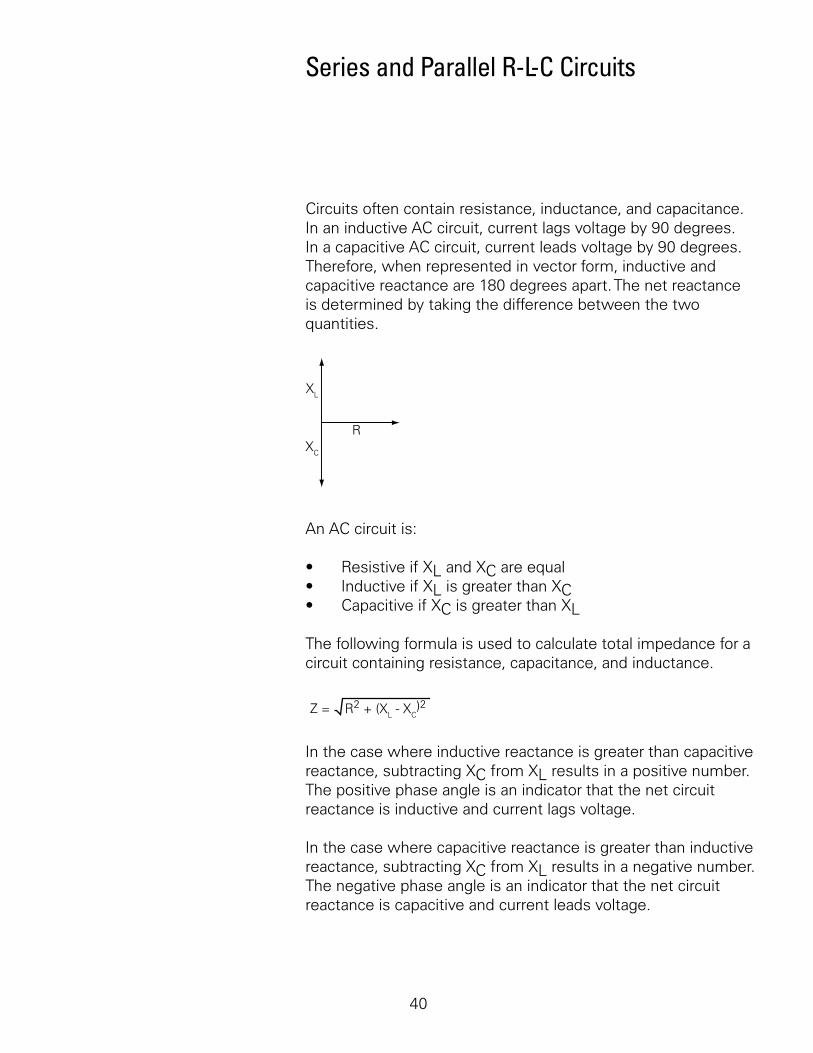
Circuits.often.contain.resistance,.inductance,.and.capacitance..In.an.inductive.AC.circuit,.current.lags.voltage.by.0.degrees..In.a.capacitive.AC.circuit,.current.leads.voltage.by.0.degrees..Therefore,.when.represented.in.vector.form,.inductive.and.capacitive.reactance.are.80.degrees.apart..The.net.reactance.is.determined.by.taking.the.difference.between.the.two.quantities.
R
XL
XC
An.AC.circuit.is:
•. Resistive.if.XL.and.XC.are.equal•. Inductive.if.XL.is.greater.than.XC•. Capacitive.if.XC.is.greater.than.XL
The.following.formula.is.used.to.calculate.total.impedance.for.a.circuit.containing.resistance,.capacitance,.and.inductance.
Z = R2 + (XL - XC)2
In.the.case.where.inductive.reactance.is.greater.than.capacitive.reactance,.subtracting.XC.from.XL.results.in.a.positive.number..The.positive.phase.angle.is.an.indicator.that.the.net.circuit.reactance.is.inductive.and.current.lags.voltage.
In.the.case.where.capacitive.reactance.is.greater.than.inductive.reactance,.subtracting.XC.from.XL.results.in.a.negative.number..The.negative.phase.angle.is.an.indicator.that.the.net.circuit.reactance.is.capacitive.and.current.leads.voltage..
4
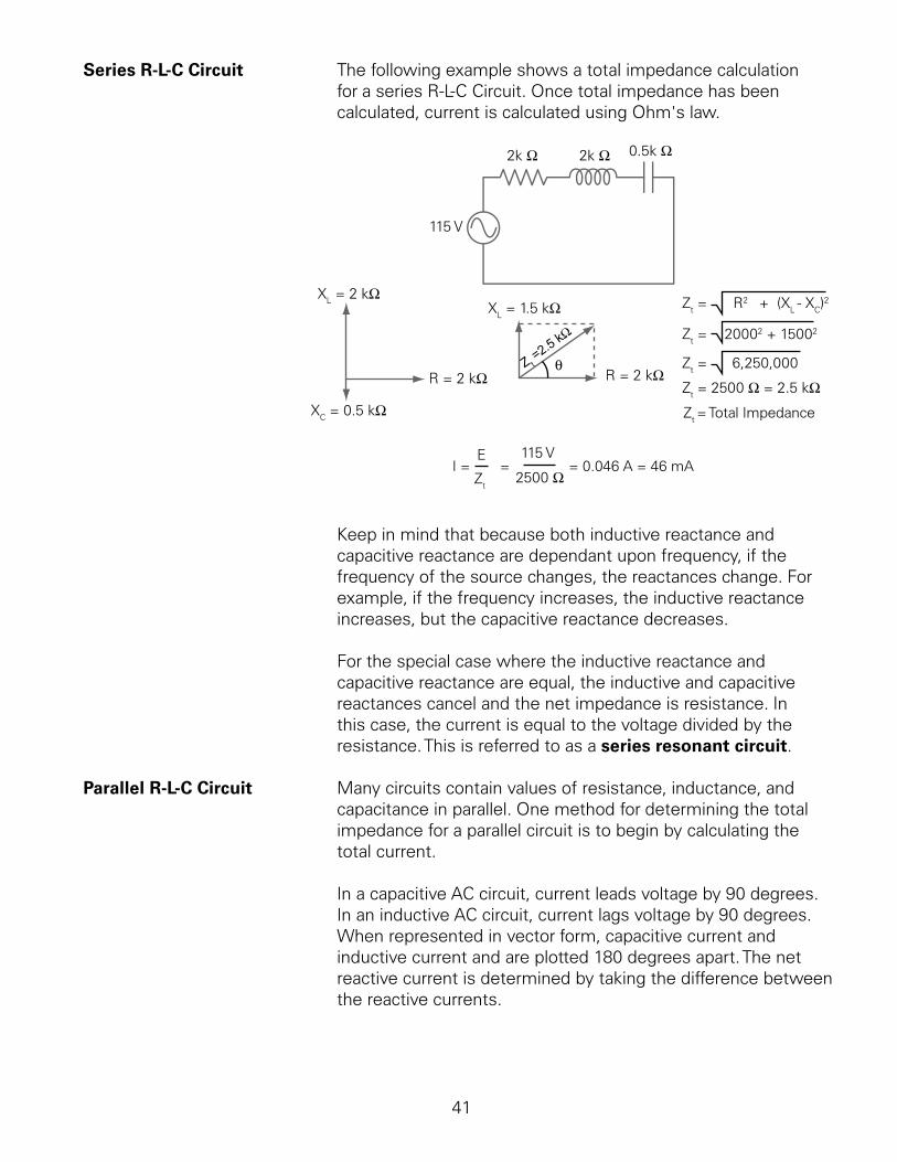
Series R-L-C Circuit The.following.example.shows.a.total.impedance.calculationfor.a.series.R-L-C.Circuit..Once.total.impedance.has.been.calculated,.current.is.calculated.using.Ohm's.law.
2k Ω 2k Ω 0.5k Ω
XC = 0.5 kΩ
XL = 2 kΩ
R = 2 kΩ
XL = 1.5 kΩ
R = 2 kΩ
Zt = R2 + (XL - XC)2
Zt = 20002 + 15002
Zt = 6,250,000
Zt = 2500 Ω = 2.5 kΩθZ t =
2.5 kΩ
115 V
I = E
Zt
=115 V
2500 Ω= 0.046 A = 46 mA
Zt = Total Impedance
Keep.in.mind.that.because.both.inductive.reactance.and.capacitive.reactance.are.dependant.upon.frequency,.if.the.frequency.of.the.source.changes,.the.reactances.change..For.example,.if.the.frequency.increases,.the.inductive.reactance.increases,.but.the.capacitive.reactance.decreases.
For.the.special.case.where.the.inductive.reactance.and.capacitive.reactance.are.equal,.the.inductive.and.capacitive.reactances.cancel.and.the.net.impedance.is.resistance..In.this.case,.the.current.is.equal.to.the.voltage.divided.by.the.resistance..This.is.referred.to.as.a.series resonant circuit.
Parallel R-L-C Circuit. Many.circuits.contain.values.of.resistance,.inductance,.and.capacitance.in.parallel..One.method.for.determining.the.total.impedance.for.a.parallel.circuit.is.to.begin.by.calculating.the.total.current..
In.a.capacitive.AC.circuit,.current.leads.voltage.by.0.degrees..In.an.inductive.AC.circuit,.current.lags.voltage.by.0.degrees..When.represented.in.vector.form,.capacitive.current.and.inductive.current.and.are.plotted.80.degrees.apart..The.net.reactive.current.is.determined.by.taking.the.difference.between.the.reactive.currents.
42
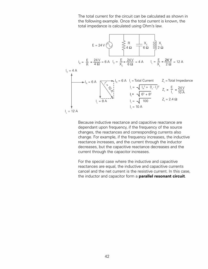
The.total.current.for.the.circuit.can.be.calculated.as.shown.in.the.following.example..Once.the.total.current.is.known,.the.total.impedance.is.calculated.using.Ohm’s.law.
E = 24 VR XC XL
IR = ER
=24 V4 Ω
= 6 A IC = EXC
= 24 V6 Ω
= 4 A IL =EXL
= 24 V2 Ω
= 12 A
IC = 4 A
IR = 6 A
IL = 12 A
IR = 6 A
IL = 8 AI
t = 10 A
It = IR2 + (Ic - IL)
2
It = 62 + 82
It = 100
It = 10 A
Zt =EIt
=24 V10 A
Zt = 2.4 Ω
It = Total Current Zt = Total Impedance
4 Ω 6 Ω 2 Ω
Because.inductive.reactance.and.capacitive.reactance.are.dependant.upon.frequency,.if.the.frequency.of.the.source.changes,.the.reactances.and.corresponding.currents.also.change..For.example,.if.the.frequency.increases,.the.inductive.reactance.increases,.and.the.current.through.the.inductor.decreases,.but.the.capacitive.reactance.decreases.and.the.current.through.the.capacitor.increases.
For.the.special.case.where.the.inductive.and.capacitive.reactances.are.equal,.the.inductive.and.capacitive.currents.cancel.and.the.net.current.is.the.resistive.current..In.this.case,.the.inductor.and.capacitor.form.a.parallel resonant circuit.
43
Power and Power Factor in an AC Circuit
Power.consumed.by.a.resistor.is.dissipated.in.heat.and.not.returned.to.the.source..This.is.called.true power.because.it.is.the.rate.at.which.energy.is.used..
Current.in.an.AC.circuit.rises.to.peak.values.and.diminishes.to.zero.many.times.a.second..The.energy.stored.in.the.magnetic.field.of.an.inductor,.or.plates.of.a.capacitor,.is.returned.to.the.source.when.current.changes.direction..
Although.reactive.components.do.not.consume.energy,.they.do.increase.the.amount.of.energy.that.must.be.generated.to.do.the.same.amount.of.work..The.rate.at.which.this.non-working.energy.must.be.generated.is.called.reactive power..If.voltage.and.current.are.0.degrees.out.of.phase,.as.would.be.the.case.in.a.purely.capacitive.or.purely.inductive.circuit,.the.average.value.of.true.power.is.equal.to.zero..In.this.case,.there.are.high.positive.and.negative.peak.values.of.power,.but.when.added.together.the.result.is.zero.
Power.in.an.AC.circuit.is.the.vector.sum.of.true.power.and.reactive.power..This.is.called.apparent power..True.power.is.equal.to.apparent.power.in.a.purely.resistive.circuit.because.voltage.and.current.are.in.phase..Voltage.and.current.are.also.in.phase.in.a.circuit.containing.equal.values.of.inductive.reactance.and.capacitive.reactance..In.most.circuits,.however,.apparent.power.is.composed.of.both.true.power.and.reactive.power.
The.formula.for.apparent.power.is.shown.below..The.unit.of.measure.for.apparent.power.is.the.volt-ampere (VA).
Power FormulasP = EI
True.power.is.calculated.from.another.trigonometric.function,.the.cosine.of.the.phase.angle.(cos.q)..The.formula.for.true.power.is.shown.below..The.unit.of.measure.for.true.power.is.the.watt (W).
P = EI cos θ
44
In.a.purely.resistive.circuit,.current.and.voltage.are.in.phase.and.there.is.a.zero.degree.angle.displacement.between.current.and.voltage..The.cosine.of.zero.is.one..Multiplying.a.value.by.one.does.not.change.the.value..Therefore,.in.a.purely.resistive.circuit,.the.cosine.of.the.angle.is.ignored.
In.a.purely.reactive.circuit,.either.inductive.or.capacitive,.current.and.voltage.are.0.degrees.out.of.phase..The.cosine.of.0.degrees.is.zero..Multiplying.a.value.times.zero.results.in.a.zero.product..Therefore,.no.energy.is.consumed.in.a.purely.reactive.circuit.
Although.reactive.components.do.not.consume.energy,.they.do.increase.the.amount.of.energy.that.must.be.generated.to.do.the.same.amount.of.work..The.rate.at.which.this.non-working.energy.must.be.generated.is.called.reactive.power..The.unit.for.reactive.power.the.var.(or.VAr),.which.stands.for.volt-ampere.reactive.
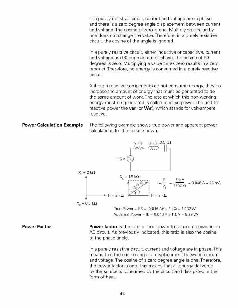
Power Calculation Example. The.following.example.shows.true.power.and.apparent.power.calculations.for.the.circuit.shown.
True Power = I2R = (0.046 A)2 x 2 kΩ = 4.232 W
Apparent Power = IE = 0.046 A x 115 V = 5.29 VA
2 kΩ 2 kΩ 0.5 kΩ
XC = 0.5 kΩ
XL = 2 kΩ
R = 2 kΩ
XL = 1.5 kΩ
R = 2 kΩθZ t
=2.5k Ω
115 V
I = E
Zt
=115 V
2500 Ω= 0.046 A = 46 mA
Power Factor. Power factor.is.the.ratio.of.true.power.to.apparent.power.in.an.AC.circuit..As.previously.indicated,.this.ratio.is.also.the.cosine.of.the.phase.angle.
In.a.purely.resistive.circuit,.current.and.voltage.are.in.phase..This.means.that.there.is.no.angle.of.displacement.between.current.and.voltage..The.cosine.of.a.zero.degree.angle.is.one..Therefore,.the.power.factor.is.one..This.means.that.all.energy.delivered.by.the.source.is.consumed.by.the.circuit.and.dissipated.in.the.form.of.heat.
45
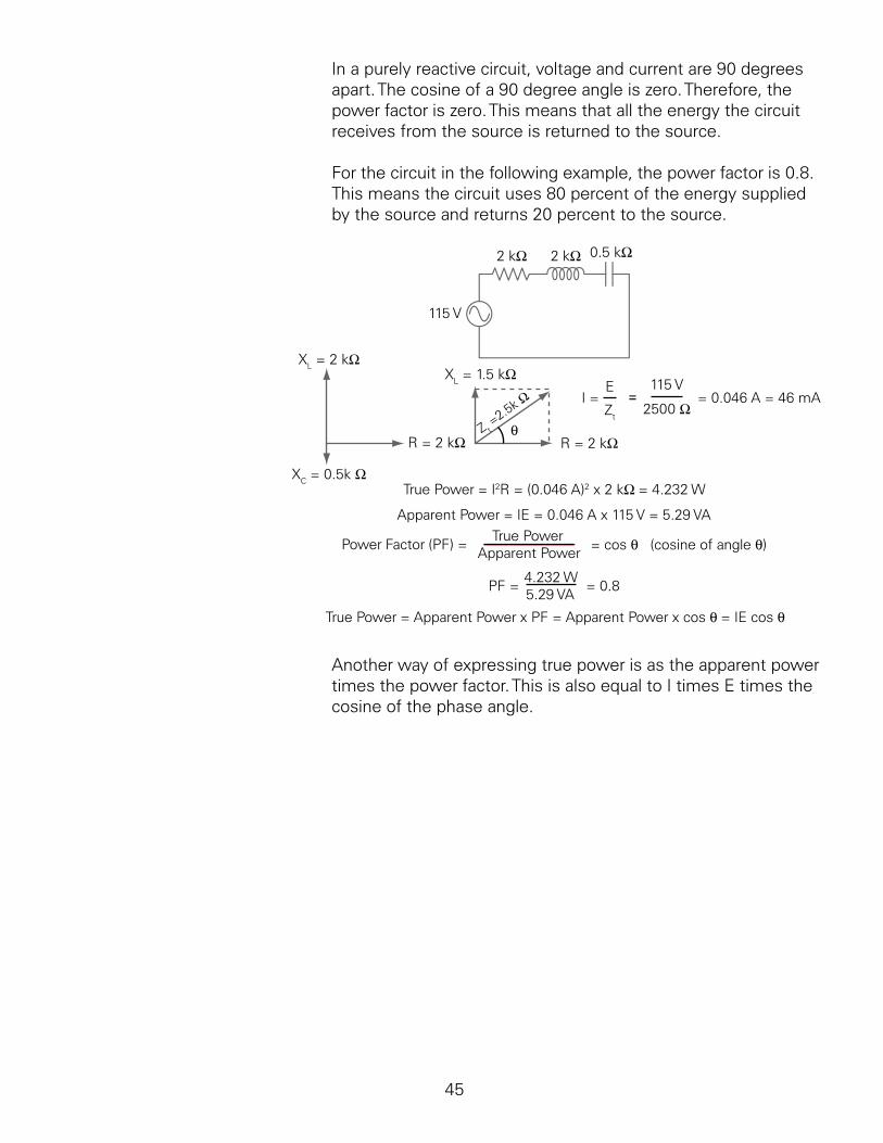
In.a.purely.reactive.circuit,.voltage.and.current.are.0.degrees.apart..The.cosine.of.a.0.degree.angle.is.zero..Therefore,.the.power.factor.is.zero..This.means.that.all.the.energy.the.circuit.receives.from.the.source.is.returned.to.the.source.
For.the.circuit.in.the.following.example,.the.power.factor.is.0.8..This.means.the.circuit.uses.80.percent.of.the.energy.supplied.by.the.source.and.returns.20.percent.to.the.source.
True Power = I2R = (0.046 A)2 x 2 kΩ = 4.232 W
Apparent Power = IE = 0.046 A x 115 V = 5.29 VA
2 kΩ 2 kΩ 0.5 kΩ
115 V
XC = 0.5k Ω
XL = 2 kΩ
R = 2 kΩ
XL = 1.5 kΩ
R = 2 kΩθZ t
=2.5k Ω I = E
Zt
=115 V
2500 Ω= 0.046 A = 46 mA
Power Factor (PF) =True Power
Apparent Power= cos θ (cosine of angle θ)
PF =4.232 W5.29 VA
= 0.8
True Power = Apparent Power x PF = Apparent Power x cos θ = IE cos θ
Another.way.of.expressing.true.power.is.as.the.apparent.power.times.the.power.factor..This.is.also.equal.to.I.times.E.times.the.cosine.of.the.phase.angle.
46
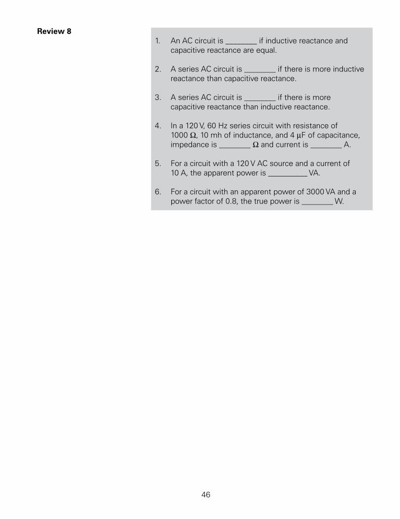
Review 8.. An.AC.circuit.is.________.if.inductive.reactance.and.
capacitive.reactance.are.equal.
2.. A.series.AC.circuit.is.________.if.there.is.more.inductive.reactance.than.capacitive.reactance.
3.. A.series.AC.circuit.is.________.if.there.is.more.capacitive.reactance.than.inductive.reactance.
4.. In.a.20.V,.60.Hz.series.circuit.with.resistance.of.000.W,.0.mh.of.inductance,.and.4.mF.of.capacitance,.impedance.is.________.W.and.current.is.________.A.
5.. For.a.circuit.with.a.20.V.AC.source.and.a.current.of.0.A,.the.apparent.power.is.__________.VA.
6.. For.a.circuit.with.an.apparent.power.of.3000.VA.and.a.power.factor.of.0.8,.the.true.power.is.________.W.

47
Transformers
Transformers.are.electromagnetic.devices.that.transfer.electrical.energy.from.one.circuit.to.another.by.mutual induction..A.single-phase.transformer.has.two.coils,.a.primary.and.a.secondary..Mutual.induction.is.the.transfer.of.electrical.energy.from.the.primary.to.the.secondary.through.magnetic.fields...For.example,.in.the.following.a.single-phase.transformer.circuit..The.AC.generator.provides.electrical.power.to.the.primary.coil..The.magnetic.field.produced.by.the.primary.induces.a.voltage.into.the.secondary.coil,.which.supplies.power.to.a.load.
AC Source Load
Single-phase, Iron Core Transformer
PrimaryCoil
SecondaryCoil
Transformers.are.used.to.step.a.voltage.up.to.a.higher.level,.or.down.to.a.lower.level..To.understand.the.need.to.stepping.up.or.down.voltages,.consider.how.electrical.power.is.generated.and.distributed.
Generators.used.by.power.companies.typically.generate.voltages.of.30.kV.or.less..While.this.is.a.relatively.high.voltage.compared.to.the.voltages.used.by.power.customers,.it.is.more.efficient.for.utilities.to.transmit.this.power.at.still.higher.voltages,.up.to.as.high.at.765.kV..
The.electrical.power.is.received.at.substation.transformers.many.miles.away.where.it.is.stepped.down.and.distributed.locally..When.it.arrives.at.the.customer’s.location,.it.is.further.stepped.down.to.the.level.needed.for.the.type.of.customer.
Even.within.a.customer’s.facility,.voltage.may.need.to.be.stepped.down.further.to.meet.requirements.of.some.equipment.
48
This.process.of.stepping.up.or.down.the.voltage.throughout.a.power.distribution.system.is.accomplished.using.transformers..The.size.and.ratings.of.the.transformers.vary,.but.the.basic.operation.of.these.devices.is.the.same.
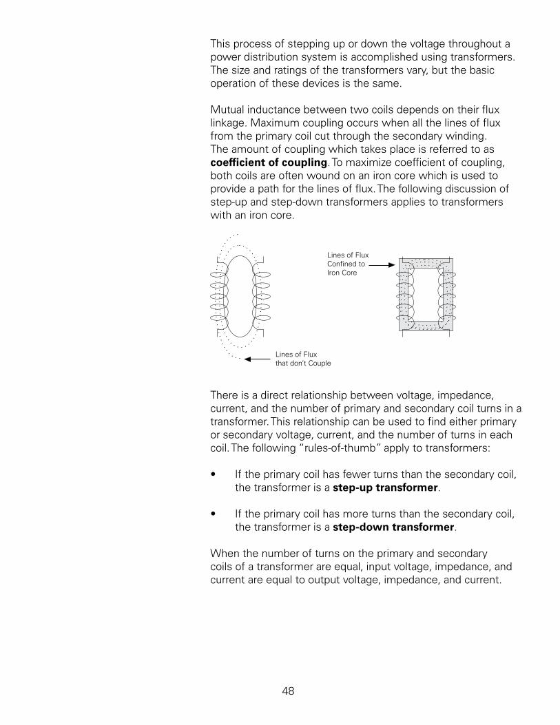
Mutual.inductance.between.two.coils.depends.on.their.flux.linkage..Maximum.coupling.occurs.when.all.the.lines.of.flux.from.the.primary.coil.cut.through.the.secondary.winding..The.amount.of.coupling.which.takes.place.is.referred.to.as.coefficient of coupling..To.maximize.coefficient.of.coupling,.both.coils.are.often.wound.on.an.iron.core.which.is.used.to.provide.a.path.for.the.lines.of.flux..The.following.discussion.of.step-up.and.step-down.transformers.applies.to.transformers.with.an.iron.core.
Lines of FluxConfined to Iron Core
Lines of Fluxthat don’t Couple
There.is.a.direct.relationship.between.voltage,.impedance,.current,.and.the.number.of.primary.and.secondary.coil.turns.in.a.transformer..This.relationship.can.be.used.to.find.either.primary.or.secondary.voltage,.current,.and.the.number.of.turns.in.each.coil..The.following.“rules-of-thumb”.apply.to.transformers:
•. If.the.primary.coil.has.fewer.turns.than.the.secondary.coil,.the.transformer.is.a.step-up transformer.
•. If.the.primary.coil.has.more.turns.than.the.secondary.coil,.the.transformer.is.a.step-down transformer.
When.the.number.of.turns.on.the.primary.and.secondary.coils.of.a.transformer.are.equal,.input.voltage,.impedance,.and.current.are.equal.to.output.voltage,.impedance,.and.current.
4
Transformer Formulas. There.are.a.number.of.useful.formulas.for.calculating,.voltage,.current,.and.the.number.of.turns.between.the.primary.and.secondary.of.a.transformer..These.formulas.can.be.used.with.either.step-up.or.step-down.transformers..The.following.legend.applies.to.the.transformer.formulas:
ES.=.secondary.voltageEP.=.primary.voltageIS.=.secondary.currentIP.=.primary.currentNS.=.turns.in.the.secondary.coilNP.=.turns.in.the.primary.coil
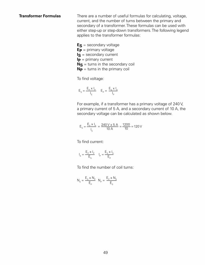
To.find.voltage:
ES =EP x IP EP =
ES x ISIS IP
For.example,.if.a.transformer.has.a.primary.voltage.of.240.V,.a.primary.current.of.5.A,.and.a.secondary.current.of.0.A,.the.secondary.voltage.can.be.calculated.as.shown.below.
ES =EP x IP 240 V x 5 A
10 A1200
10
IS= 120 V= =
To.find.current:
IS =EP x IP IP =
ES x ISES EP
To.find.the.number.of.coil.turns:
NS =ES x NP NP =
EP x NS
EP ES
50
Transformer Ratings. Transformers.are.rated.for.the.amount.of.apparent.power.they.can.provide..Because.values.of.apparent.power.are.often.large,.the.transformer.apparent.power.rating.is.frequently.given.in.kVA (kilovolt-amperes)..The.kVA.rating.determines.the.current.and.voltage.a.transformer.can.deliver.to.its.load.without.overheating..
For.a.single-phase.transformer,.the.apparent.power.rating.is.calculated.by.multiplying.secondary.voltage.by.the.maximum.load.current..This.means.that.if.a.transformer.needs.to.provide.a.secondary.voltage.of.240.V.at.a.maximum.load.current.of.75.A,.the.kVA.rating.of.the.transformer.must.be.at.least.8.kVA..
240 V x 75 A = 18,000 VA = 18 kVA
Transformer Losses. Most.of.the.electrical.energy.provided.to.the.primary.of.a.transformer.is.transferred.to.the.secondary..Some.energy,.however,.is.lost.in.heat.in.the.wiring.or.the.core..Some.losses.in.the.core.can.be.reduced.by.building.the.core.of.a.number.of.flat.sections.called.laminations.
Three-Phase AC. Up.till.now,.we.have.been.talking.only.about.single-phase AC power..Single-phase.power.is.used.in.homes,.offices,.and.many.other.types.of.facilities..
However,.power.companies.generate.and.distribute.three-phase power..Three-phase.power.is.used.in.commercial.and.industrial.applications.that.have.higher.power.requirements.than.a.typical.residence.
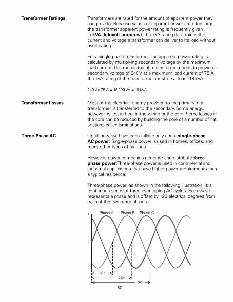
Three-phase.power,.as.shown.in.the.following.illustration,.is.a.continuous.series.of.three.overlapping.AC.cycles..Each.wave.represents.a.phase.and.is.offset.by.20.electrical.degrees.from.each.of.the.two.other.phases.
Phase A Phase B Phase C+
0
-120o
240o
360o
5
Three-Phase Transformers. Three-phase transformers.are.used.when.three-phase.power.is.required.for.larger.loads.such.as.industrial.motors..There.are.two.basic.three-phase.transformer.connections,.delta.and.wye..
Delta Connections. Delta.transformers.are.schematically.drawn.in.a.triangle..The.voltages.across.each.winding.of.the.delta.triangle.represents.one.phase.of.a.three.phase.system..The.voltage.is.always.the.same.between.any.two.wires..A.single.phase.(such.as.L.to.L2).can.be.used.to.supply.single.phase.loads..All.three.phases.are.used.to.supply.three.phase.loads.
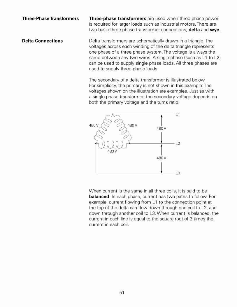
The.secondary.of.a.delta.transformer.is.illustrated.below..For.simplicity,.the.primary.is.not.shown.in.this.example..The.voltages.shown.on.the.illustration.are.examples..Just.as.with.a.single-phase.transformer,.the.secondary.voltage.depends.on.both.the.primary.voltage.and.the.turns.ratio.
480 V 480 V
480 V
480 V
480 V
L1
L3
L2
When.current.is.the.same.in.all.three.coils,.it.is.said.to.be.balanced..In.each.phase,.current.has.two.paths.to.follow..For.example,.current.flowing.from.L.to.the.connection.point.at.the.top.of.the.delta.can.flow.down.through.one.coil.to.L2,.and.down.through.another.coil.to.L3..When.current.is.balanced,.the.current.in.each.line.is.equal.to.the.square.root.of.3.times.the.current.in.each.coil..
52
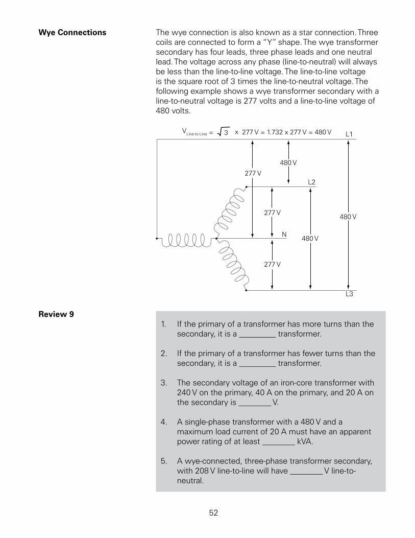
Wye Connections. The.wye.connection.is.also.known.as.a.star.connection..Three.coils.are.connected.to.form.a.“Y”.shape..The.wye.transformer.secondary.has.four.leads,.three.phase.leads.and.one.neutral.lead..The.voltage.across.any.phase.(line-to-neutral).will.always.be.less.than.the.line-to-line.voltage..The.line-to-line.voltage.is.the.square.root.of.3.times.the.line-to-neutral.voltage..The.following.example.shows.a.wye.transformer.secondary.with.a.line-to-neutral.voltage.is.277.volts.and.a.line-to-line.voltage.of.480.volts.
277 V
277 V
277 V
480 V
480 V
480 V
L1
L2
L3
N
VLine-to-Line = 3 x 277 V = 1.732 x 277 V = 480 V
Review 9.. If.the.primary.of.a.transformer.has.more.turns.than.the.
secondary,.it.is.a._________.transformer.
2.. If.the.primary.of.a.transformer.has.fewer.turns.than.the.secondary,.it.is.a._________.transformer.
3.. The.secondary.voltage.of.an.iron-core.transformer.with.240.V.on.the.primary,.40.A.on.the.primary,.and.20.A.on.the.secondary.is.________.V.
4.. A.single-phase.transformer.with.a.480.V.and.a.maximum.load.current.of.20.A.must.have.an.apparent.power.rating.of.at.least.________.kVA.
5.. A.wye-connected,.three-phase.transformer.secondary,.with.208.V.line-to-line.will.have.________.V.line-to-neutral.
53
Review Answers
Review 1. ).electron.(-),.proton.(+),.neutron.(neutral);.2).conductors;.3).a,.c,.e,.g;.4).insulators.
Review 2. ).negative;.2).positive;.3).repel,.attract;.f).Voltage;.. 6).negative,.positive;.7).a..ohm,.b..ampere,.c..volt.
Review 3. ).0.5;.2).45;.3).30;.4).5;.5).6;.6).20.
Review 4. ).iron,.north-south;.2).north,.south;.3).electron,.lines.of.flux.
Review 5. ).sine.wave;.2).one;.3).-2.;.4).06.05.
Review 6. ).0;.2).2.5;.3).2.5;.4).25.
Review 7. ).Reactance;.2).Impedance;.3).3.4;.4).c;.5).b;.6).38.5;.7)..8;.8).6.4.
Review 8. ).resistive;.2).inductive;.3).capacitive;.4).8,.0.;.. 5).200;.6).2400..
Review 9. ).step-down;.2).step-up;.3).480;.4)..6;.5).20.

54

55

56
Final Exam
You.can.test.your.knowledge.by.taking.the.final.exam.for.this.course.online.at.http://www.usa.siemens.com/step..This.web.page.provides.links.to.a.variety.of.our.quickSTEP.online.courses..To.complete.the.final.exam.for.this.course,.click.on.the.Basics of Electricity.link..
Next,.move.your.mouse.over.to.the.left.so.that.the.navigation.bar.pops.out.and.select.the.Final Exam.link..The.final.exam.page.will.appear..Before.taking.the.final.exam,.it.is.recommended.that.you.delete.the.temporary.files.on.your.computer..For.most.versions.of.Internet Explorer,.you.can.do.this.by.selecting.Internet Options.from.the.Tools.menu.and.then.clicking.on.the.Delete Files.button..If.you.do.not.perform.this.step,.you.may.see.a.score.of.0%.after.you.submit.your.exam.for.grading.
After.you.complete.the.final.exam,.click.on.the.Grade the Exam.button.at.the.bottom.of.the.page..Your.score.on.the.exam.will.be.displayed.along.with.the.questions.that.you.missed..
If.you.score.70%.or.better.on.the.exam,.you.will.be.given.two.options.for.displaying.and.printing.a.certificate.of.completion..The.Print Certificate.option.allows.you.to.display.and.print.the.certificate.without.saving.your.score.in.our.database.and.the.Save Score.option.allows.you.to.save.your.score.and.display.and.print.your.certificate..
![Basics of Electricity [Siemens]](https://static.fdocuments.in/doc/165x107/552d59804a79593c578b4655/basics-of-electricity-siemens.jpg)