BASICS OF CONTOURING CONTOURING OF REGIONAL LNS 3 D...
80
BASICS OF CONTOURING CONTOURING OF REGIONAL LNS 3 D CT BASED PLANNING OF BCT AND PLAN EVALUATION Dr Vineeta Goel Senior Consultant Radiation Oncology Max Super Speciality Hospital New Delhi
Transcript of BASICS OF CONTOURING CONTOURING OF REGIONAL LNS 3 D...

BASICS OF CONTOURING
CONTOURING OF REGIONAL LNS
3 D CT BASED PLANNING OF BCT AND PLAN
EVALUATION
Dr Vineeta Goel
Senior Consultant Radiation Oncology
Max Super Speciality Hospital
New Delhi

Why do we need Contouring?
• RT to breast -reduces local recurrences and is a/w improved survival
• Concern- T/t related morbidity in breast and shoulder
- Long term risk of heart disease and secondary cancer
• Need to Optimize RT to obtain max effect and minimize morbidity
• Transition from 2D to 3D RT– shift from bony land mark based RT to individualised target
• Target volume delineation is the weakest link in quality chain of RT and there are large inter observer variations

Basics are still basics!
• Study Pre operative Clinical findings and diagrams well
Location of tumour
Size of tumour
+/- Tumour involving Nipple areola complex
PDO- Present/absent and its extent
Axillary/ SC LNs
• Read HPR with due attention

Model HPR Post MRM
• 6x4 cm tumour located in UIQ of Rt Breast
• IDC Grade III
• LVI present
• Deep Margin free and 1.5 cm away from tumour
• Tumour reaching up to Dermis
• Dermal lymphatic emboli present
• DCIS absent
• 4/18 LNs Positive ; largest LN 2.5 cm, ECE Present
• Triple Negative

Basics are still basics!
• Understand your patient’s body habitus well
• High BMI- sometimes helps you decide arm position/ elevation
• Check for arm’s movement
• If any lymphedema- document it
• Type of Breast-
• Atrophic – careful palpation
• Pendulous breast -identify and try to reduce folds
• Location of tumour- Tumour in Lower quadrant or inner quadrant-need to modify conventional borders

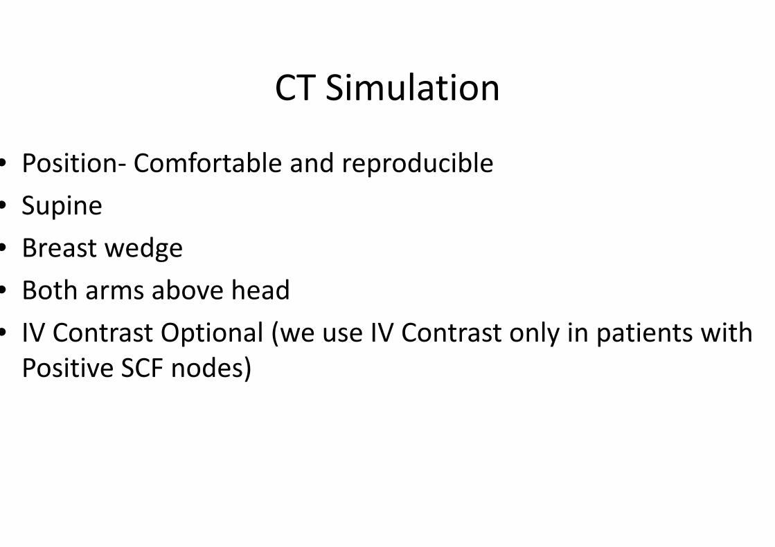
CT Simulation
• Position- Comfortable and reproducible
• Supine
• Breast wedge
• Both arms above head
• IV Contrast Optional (we use IV Contrast only in patients with
Positive SCF nodes)

• Wires-Important Step- Do not hurry!!
• Palpate Breast well, look for skin folds, mark with pen both breasts
• Wire around- I/L Breast
Scar
Opposite Breast
Provisional field borders
Use copper wires to reduce artefacts
Free Breathing
3- 5 mm scans from neck to L1-2
Pic Courtesy Dr Ashwini Budrukar

Terminology
• Medial, Lateral, Cranial, Caudal, Ventral, Dorsal
• G- Guideline
• MS- My Submission

Normal Anatomy
www.abro-bvro.be

SCM- Superficial
Ms in Neck
Manubrium
Sterni & Medial
Clavicle
Mastoid process

Scalene Ms –Deep
Neck Ms
O- Transverse
process of C3-6
- First Rib

P Major- Thick fan shaped
i) Clavicular head
Sternocostal head-
Anterior surface of
sternum and superior six
costal cartilage
Humerus

P Minor- Thin triangular Ms
3-5th Rib
Coracoid process of
Scapula

L Scapulae- Large flat
Scapula
3rd or 4th Rib
D7-L5 Vertebrae
Iliac Crest
Humerus

Origin-
Left CCA- Aortic Arch
Right CCA- Right Brachiocephalic A

Lt SCA- Aortic arch
SCA- Brachiocephalic Trunk
After Crossing Lateral Border of first rib it
becomes axillary A

Axillary A- Three parts medial, posterior and lateral to P Minor Ms
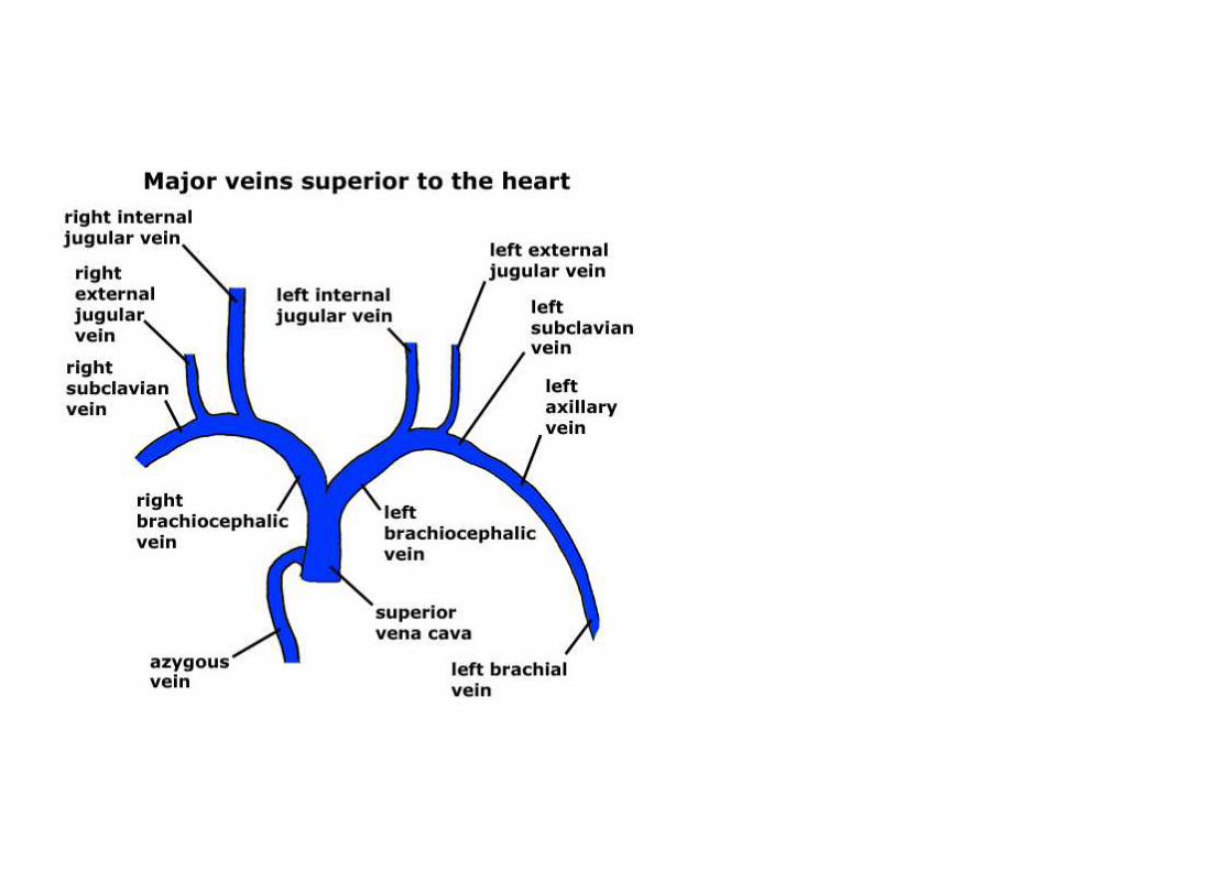

Axillary V – Drains in Subclavian V
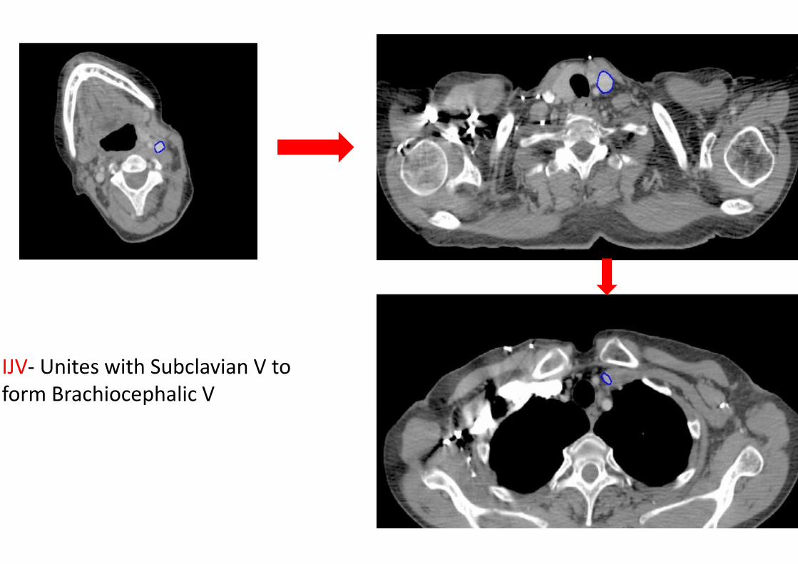
IJV- Unites with Subclavian V to
form Brachiocephalic V

Why wires around Breast?
• Large differences are reported b/w CTV localization using
standard anatomic borders, palpation and USG
• Hurkmans et al - study in 2001 with palpable breast
glandular tissue was marked by lead wire before Planning CT
in 6 pts Vs. 4 patients without lead wire
• CTV was delineated by 4 RO
• Deviations in PTV extent were greater in Posterior, Cranial
and medial directions
• Interobserver variation in volume was decreased by a factor
of 4 on scans with lead wire IJROBP Vol 50 No5, 2001

RTOG Atlas
• 9 RO from eight institutions independently
delineated targets
( Lumpectomy cavity, boost PTV, Breast, SCF,
Axillary, IMCLN and chest wall) and OARs (heart
and lungs) on same CT images of three
representative breast cancer pts
To reduce inconsistencies RTOG proposed a
breast cancer atlas
IJRBOP Vol 73(3), 944-51; 2009


Guidelines only Guide!!
• Guidelines serve as base on which CTV can be individually
adapted
• Not applicable for T/t in prone position
• RTOG – EBC and LABC
• ESTRO and Danish- EBC
• All Contours are shown- does not mean that all volumes have
to be treated
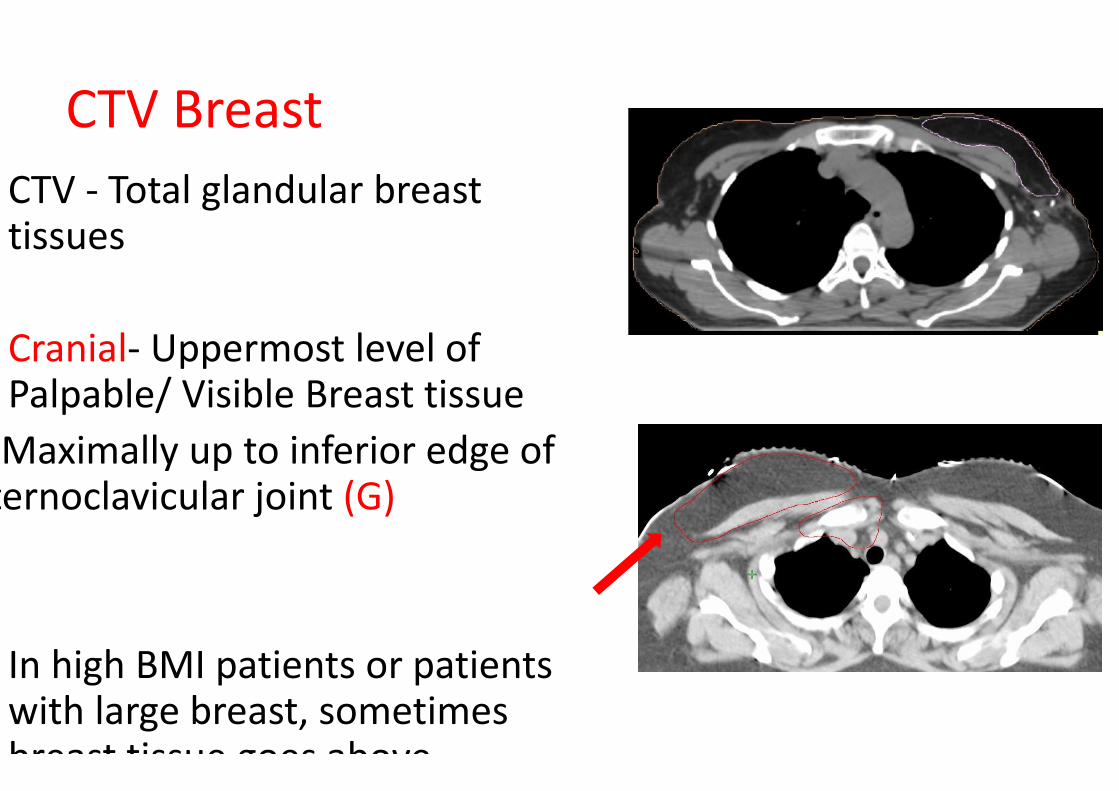
CTV Breast
CTV - Total glandular breast tissues
Cranial- Uppermost level of Palpable/ Visible Breast tissue
Maximally up to inferior edge of sternoclavicular joint (G)
In high BMI patients or patients with large breast, sometimes breast tissue goes above

Caudal- Most Caudal CT
slice with visible breast
tissue (G)
In obese patients, CTV P
Breast is positioned more
ventrally in the caudal
part of breast due to fatty
tissue (G, ESTRO)
This is actually extension
of abdominal wall fat
Helps decreasing dose to
heart

• Dorsal – Pectoral muscle or intercostal ms where there is no P Major muscle (G)
• RTOG – to include chest wall also in LABC
E
S
T
R
O
R
T
O
G

Ventral- 5mm under skin
G, ESTRO)
LABC with BCS -in cases
with T4b,c,d cancer where
full dose up to skin is
advised (bolus may be
added) (G, ESTRO, RTOG)
E
S
T
R
O
R
T
O
G

• In a thin atrophic breast
one my consider keeping
skin volumes may be 3mm
below skin (MS)
• In superficially located
tumours; skin is also a
target; one may consider a
small patch of bolus
around scar (MS)
Superficially Located Tumour

Medial- Clinical Reference / Wire
Maximal to edge of sternum
CTV P Breast is positioned lateral to mammary branch of internal
thoracic A (G, ESTRO)

• Lateral- Most difficult to
delineate ( varies
according to breast
ptosis)
� Mid Axillary Line or 1.5-2
cm beyond palpable
breast tissue
(Traditional)
• Medial to lateral
thoracic A, Breast fold
(G, ESTRO, DBCG)
• Exclude Lat Dorsi Ms
(RTOG)

Internal Thoracic A is a branch of subclavian A
Lateral Thoracic A is a branch of Axillary A

Words of Caution- Individualization!!
Encompass primary tumor bed
adequately , including relevant margins
around it
In patients with tumours placed too
medially/ laterally one needs to modify
conventional borders
Apply wires carefully even on opposite
breast as you keep comparing your
contours with opposite breast

M
S

CTV Chest Wall
• Place radio opaque wires around imaginary- original site of
breast and also on MRM scar
• Generally same as breast

CTV Chest Wall
Dorsal-
RTOG guidelines- Rib Pleural
interface (incuding ribs, IC ms and
pectroalis ms)
ESTRO- Unless invasion was
demonstrated (tumour stage T4 a-
c), no reason to routinely include
major pectoral muscle and ribs
R
T
O
G
E
S
T
R
OImpacts Lung and Heart Doses!

Most common site
of chest wall
recurrence from
surgical series (72-
100%) is within skin
and subcutaneous
tissue anterior to
pectoralis
musculature
Second MC site is
within pectoralis
IJROBP Vol 93, August 2015, Beriwal et all
Patterns of failure
MS- Individualisation

CTV Thoracic Wall
Ventral-
RTOG- Skin
ESTRO- 5 mm under skin surface
Skin Bolus of 3-5mm may be applied for
very thin CW (ESTRO is only for EBC)
MS -Skin
Inflammatory breast cancer- Up to skin
Bolus for all fractions
R
T
O
G
E
S
T
R
O

M
S

NODAL CONTOURING

National project to improve quality of Breast Radiation Therapy ,
PROCAB (PROject on CAncer of the Breast)

Supra (Infra + Retroclavicular+ Periclavicular) LN
Cranial-
RTOG -Caudal Edge Cricoid
Cartilage
PROCAB -Cranial Edge of
Subclavian A Arch
If LABC, up to level of transverse
cervical vessels
Lower Border of Cricoid
cartilage (MS)

Caudal
• RTOG-caudal edge of Clavicle
• Junction of Brachiocephalic V and Axillary V
• MS- Lower border of medial head of Clavicle

Medial
Exclude thyroid and
trachea
Medial Edge of Int carotid
A and IJV
PROCAB

Lateral
• RTOG- Cranially- Scalene ms
Caudally- Junction of
first rib and clavicle
• DBCG- Medial edge of P Minor
and Clavicle

Ventral
• Ventral- SCM, Clavicle, 5 mm below skin
• Dorsal- Cranially- Posterior to ICA and Anterior to scalene
medius ms
• Caudally- Lung

D
B
C
G

M
S

MS


Patterns of SCLNs
• To map location of gross supraclavicular LNs in patients with
breast cancer
• 62 patients with 161 SCLNs (at diagnosis or recurrence) were
eligible for this study
• Location of SC LNs were mapped on CT/MR/PETCT
• Location of LNs were then transferred on to axial CT scan of a
representative patient with both arms abducted in a typical
breast RT position
• All LNs were plotted on left side with a circle of diameter 5mm

Distribution of LNs at Diagnosis-
• 35- 40% LNs were outside RTOG SCF Volume
• Location of LNs outside RTOG volumes were
• 1. at level of thyroid cartilage- Cranial to RTOG boundaries
• 2. Posterolateral to RTOG volumes in posterior triangle
• 3. Lateral low SCF below level of transverse cervical vessels
and lateral to scalene ms or between anterior and middle
scalene muscle.
• No recurrences occurred medial to medial border of ICA


• More generous coverage of SCF in patients with SCLNs at
presentation
• Posterior triangle
• Cranial border above cricoid cartilage

PET CT- Laterally and
posteriorly located SCLNs–
Posterior Triangle

SCF and Posterior Triangle
Volumes

Indications of Axillary RT
• Not everyone needs it!
• Heavy Axillary burden with ECE
• Soft tissue deposits present in dissected axillary fat
• Inadequate axillary Dissection
• Positive SLN and AC not done

Anatomy of Axilla

Level III Axilla
Cranial P Minor inserts on Coracoid
Caudal Axillary A/V crosses medial edge of P Minor
Ventral Dorsal surface of P Major
Dorsal Ribs and IC Ms
Medial Thoracic Inlet
Lateral Medial border of P Minor

Level II Axilla
Cranial Axillary A/V crosses medial edge of P Minor
Caudal Axillary A/V crosses lateral edge of P Minor
Ventral Anterior surface of P minor
Dorsal Ribs and IC Ms
Medial Medial border of P Minor
Lateral Lateral border of P Minor

Level I Axilla
Cranial Axillary A crosses lateral edge of P Minor
Caudal P major inserts into ribs
Ventral Plane defined by anterior surface of P major and
L Dorsi
Dorsal Subscapularis
Medial Lateral border of P Minor
Lateral Medial border of Lat Dorsi

Interpectoral LNs
Cranial Axillary A crosses medial edge of P Minor
Caudal Caudal border of P Minor
Ventral Dorsal surface of P major
Dorsal Ventral surface of P Minor
Medial Medial border of P Minor
Lateral Lateral border of P Major
ESTRO

I/C of IMC LN
• Presence Of IMC
LNs
• Central or Medial
Quadrant tumour
with Heavy axillary
LN positivity

Internal
Mammary LNsCranial Junction of SCV and Juglar V/ cranial aspect of
1st Rib (and Caudal border of SCF)
Caudal Cranial aspect of 4th Rib
Ventral Cranially- Manubrium Sterni
Caudally- Dorsal surface of IC Ms
Dorsal 5 mm space dorsal of IM Vessels, not beyond
pleura
Medial 5 mm space medial of IM Vessels
Lateral 5 mm space lateral of IM Vessels
OARS
• Heart- Contoured below pulmonary trunk bifurcation
• Coronaries
• All mediastinal tissue below this level should be contoured
including great vessels
• I/L and C/L Lungs
• Opposite Breast
• Head of Humerus

• Plan Generation
• 3 DCRT
• Forward IMRT- Field in Field
• Hybrid IMRT

Set user origin
Join medial and lateral markers
Slide Courtesy Dr Ashwini Budrukar

Lateral tangent
Slide Courtesy Dr Ashwini Budrukar

COBALT -2 field, no wedge
Slide Courtesy Dr Ashwini Budrukar

BAD PLANSCOBALT with WEDGE
Slide Courtesy Dr Ashwini Budrukar

6 MV, 2-field
showing dose
inhomogeneity
superiorly and
inferiorly
Slide Courtesy Dr
Ashwini
Budrukar

6 MV photons with 15
degree wedge in lateral
tangent

Forward IMRT
Field-in-field technique:
• Medial and lateral tangents are first planned and dose
distribution noted.
• Areas of high dose are then contoured/delineated.
• A new field is created within the existing tangential field with
an appropriate MLC configuration so as to reduce the
inhomogeneity in these areas.
• These fields are finally fused by the treatment planning system.

Forward Planned IMRT
Multiple
subfields in each
tangent
All the subfields
merged to form
dynamic MLC
motion

Hybrid IMRT
• Add Bilateral open Tangential fields
• Add Bilateral IMRT Tangential Fields to reduce dose
inhomogeneity and reduce high doses to ipsilateral lung and
heart

DVH
• Evaluate both CTV and PTV –
PTV Ideal Acceptable
D95% 95%
D90% 90%
Dmax < 115% <120%

OAR Doses
C/L Breast D max <3Gy
I/L Lung V 20Gy <15 -20%
I/L Lung V 10Gy <35 -40%
I/L Lung V 5Gy <50 -55%
C/L Lung V5 Gy <10% -15%
Heart (Left Breast Cancer) V20Gy <10%
Heart (Left Breast Cancer) V10Gy <30%
Heart (Right Breast Cancer) V20Gy 0%
Heart (Right Breast Cancer) V10Gy <10 -15%
Mean <4 -5Gy

OAR Doses -HF
CF HF
I/L Lung V 20Gy V 16Gy
V 10 Gy V 8 Gy
V 5Gy V 4Gy
Heart V 25Gy V 20 Gy
V 20Gy V 16Gy

THANKS