BASIC: SMH8165B MODEL: SMH8165W MODEL CODE: SMH8165W/XAC...
50
Refer to the service manual in the GSPN(see rear cover) for the more information. 1. Precaution 2. Product Specification 3. Disassembly and Reassembly 4. Troubleshooting 5. Exploded Views and Part List 6. PCB Diagrams 7. Wiring Diagrams 8. Schematic Diagrams BASIC: SMH8165B MODEL: SMH8165W MODEL CODE: SMH8165W/XAC Version: 00,01
Transcript of BASIC: SMH8165B MODEL: SMH8165W MODEL CODE: SMH8165W/XAC...
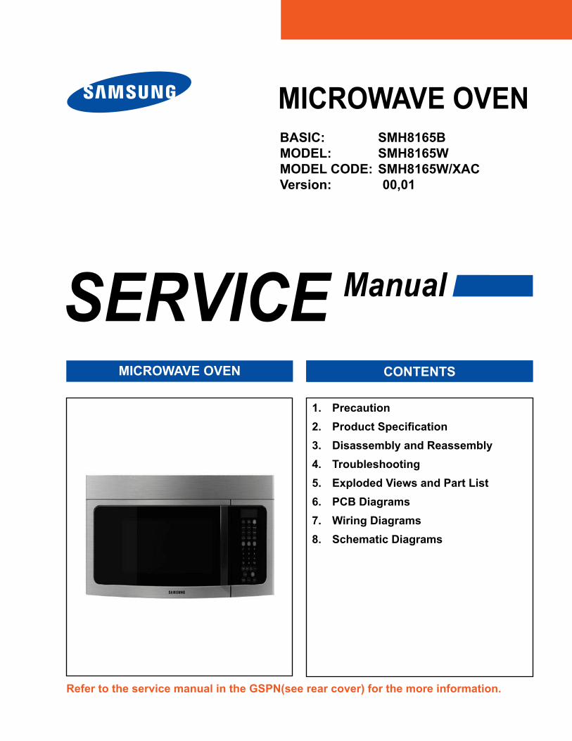
Refer to the service manual in the GSPN(see rear cover) for the more information.
1. Precaution2. ProductSpecification3. Disassembly and Reassembly4. Troubleshooting5. Exploded Views and Part List6. PCB Diagrams7. Wiring Diagrams8. Schematic Diagrams
BASIC: SMH8165BMODEL: SMH8165WMODEL CODE: SMH8165W/XACVersion: 00,01
�
• Contents
1. Precaution . . . . . . . . . . . . . . . . . . . . . . . . . . . . . . . . . . . . . . . . . . . . . . . . . . . . . . . . . . . . . . . . . . . . . . . . . . . . . .31-1 Safety precautions . . . . . . . . . . . . . . . . . . . . . . . . . . . . . . . . . . . . . . . . . . . . . . . . . . . . . . . . . . . . . . . . . . . . .41-2 Special High Voltage Precautions . . . . . . . . . . . . . . . . . . . . . . . . . . . . . . . . . . . . . . . . . . . . . . . . . . . . . . . . .5
2.Specifications . . . . . . . . . . . . . . . . . . . . . . . . . . . . . . . . . . . . . . . . . . . . . . . . . . . . . . . . . . . . . . . . . . . . . . . . . . .62-1 Features . . . . . . . . . . . . . . . . . . . . . . . . . . . . . . . . . . . . . . . . . . . . . . . . . . . . . . . . . . . . . . . . . . . . . . . . . . . . .62-2 Accessory . . . . . . . . . . . . . . . . . . . . . . . . . . . . . . . . . . . . . . . . . . . . . . . . . . . . . . . . . . . . . . . . . . . . . . . . . . . .62-3 Table of Specifications . . . . . . . . . . . . . . . . . . . . . . . . . . . . . . . . . . . . . . . . . . . . . . . . . . . . . . . . . . . . . . . . . .7
3. Disassembly and Reassembly . . . . . . . . . . . . . . . . . . . . . . . . . . . . . . . . . . . . . . . . . . . . . . . . . . . . . . . . . . . . . .83-1 Replacement of High Voltage Transformer . . . . . . . . . . . . . . . . . . . . . . . . . . . . . . . . . . . . . . . . . . . . . . . . . .83-2 Replacement of Magnetron . . . . . . . . . . . . . . . . . . . . . . . . . . . . . . . . . . . . . . . . . . . . . . . . . . . . . . . . . . . . .103-3 Replacement of Door Assembly . . . . . . . . . . . . . . . . . . . . . . . . . . . . . . . . . . . . . . . . . . . . . . . . . . . . . . . . . . 113-4 Replacement of Fuse . . . . . . . . . . . . . . . . . . . . . . . . . . . . . . . . . . . . . . . . . . . . . . . . . . . . . . . . . . . . . . . . . .133-5 Replacement of Drive Motor . . . . . . . . . . . . . . . . . . . . . . . . . . . . . . . . . . . . . . . . . . . . . . . . . . . . . . . . . . . .133-6 Replacement of stirrer motor . . . . . . . . . . . . . . . . . . . . . . . . . . . . . . . . . . . . . . . . . . . . . . . . . . . . . . . . . . . .143-7 Removal of stirrer . . . . . . . . . . . . . . . . . . . . . . . . . . . . . . . . . . . . . . . . . . . . . . . . . . . . . . . . . . . . . . . . . . . . .153-8 Replacement of Control Circuit Board . . . . . . . . . . . . . . . . . . . . . . . . . . . . . . . . . . . . . . . . . . . . . . . . . . . . .163-9 Replacement of Cooktop lamp . . . . . . . . . . . . . . . . . . . . . . . . . . . . . . . . . . . . . . . . . . . . . . . . . . . . . . . . . . .173-10 Replacement of Oven Light . . . . . . . . . . . . . . . . . . . . . . . . . . . . . . . . . . . . . . . . . . . . . . . . . . . . . . . . . . . .18
4. Troubleshooting . . . . . . . . . . . . . . . . . . . . . . . . . . . . . . . . . . . . . . . . . . . . . . . . . . . . . . . . . . . . . . . . . . . . . . . .194-1 Error Code Numbering Rule . . . . . . . . . . . . . . . . . . . . . . . . . . . . . . . . . . . . . . . . . . . . . . . . . . . . . . . . . . . . .194-2 Error Code List . . . . . . . . . . . . . . . . . . . . . . . . . . . . . . . . . . . . . . . . . . . . . . . . . . . . . . . . . . . . . . . . . . . . . . .194-3 Electrical Malfunction . . . . . . . . . . . . . . . . . . . . . . . . . . . . . . . . . . . . . . . . . . . . . . . . . . . . . . . . . . . . . . . . . .204-4 Electrical Malfunction . . . . . . . . . . . . . . . . . . . . . . . . . . . . . . . . . . . . . . . . . . . . . . . . . . . . . . . . . . . . . . . . . .24
5. Exploded Views and Parts List . . . . . . . . . . . . . . . . . . . . . . . . . . . . . . . . . . . . . . . . . . . . . . . . . . . . . . . . . . . .�75-1 Exploded Views (00,01Version) . . . . . . . . . . . . . . . . . . . . . . . . . . . . . . . . . . . . . . . . . . . . . . . . . . . . . . . . . .275-2 Version List (00,01Version) . . . . . . . . . . . . . . . . . . . . . . . . . . . . . . . . . . . . . . . . . . . . . . . . . . . . . . . . . . . . .295-3 Main Parts List (00,01Version) . . . . . . . . . . . . . . . . . . . . . . . . . . . . . . . . . . . . . . . . . . . . . . . . . . . . . . . . . . .305-4 Door Parts List (00,01Version) . . . . . . . . . . . . . . . . . . . . . . . . . . . . . . . . . . . . . . . . . . . . . . . . . . . . . . . . . . .345-5 Control Parts List (00,01Version) . . . . . . . . . . . . . . . . . . . . . . . . . . . . . . . . . . . . . . . . . . . . . . . . . . . . . . . . .365-6 Standard Parts List (00,01Version) . . . . . . . . . . . . . . . . . . . . . . . . . . . . . . . . . . . . . . . . . . . . . . . . . . . . . . .38
6. PCB Diagrams . . . . . . . . . . . . . . . . . . . . . . . . . . . . . . . . . . . . . . . . . . . . . . . . . . . . . . . . . . . . . . . . . . . . . . . . . .406-1 PCB Diagrams (00,01Version) . . . . . . . . . . . . . . . . . . . . . . . . . . . . . . . . . . . . . . . . . . . . . . . . . . . . . . . . . . .406-2 PCB Diagrams (00,01Version) . . . . . . . . . . . . . . . . . . . . . . . . . . . . . . . . . . . . . . . . . . . . . . . . . . . . . . . . . . .41
7. Wiring Diagrams . . . . . . . . . . . . . . . . . . . . . . . . . . . . . . . . . . . . . . . . . . . . . . . . . . . . . . . . . . . . . . . . . . . . . . . .447-1 Wiring Diagrams (00,01Version) . . . . . . . . . . . . . . . . . . . . . . . . . . . . . . . . . . . . . . . . . . . . . . . . . . . . . . . . .44
8. Schematic Diagrams . . . . . . . . . . . . . . . . . . . . . . . . . . . . . . . . . . . . . . . . . . . . . . . . . . . . . . . . . . . . . . . . . . . . .488-1 Schematic Diagrams (00,01Version) . . . . . . . . . . . . . . . . . . . . . . . . . . . . . . . . . . . . . . . . . . . . . . . . . . . . . .48
3
1. Precaution
4
1. Precaution
Follow these special safety precautions . Although the microwave oven is completely safe during ordinary use, repair work can be extremely hazardous due to possible exposure to microwave radiation, as well as potentially lethal high voltages and currents .
1-1 Safety precautions ( )1. All repairs should be done in accordance with the
procedures described in this manual . This product complies with Federal Performance Standard 21 CFR
�. Microwave emission check should be performed to prior to servicing if the oven is operative .
3. If the oven operates with the door open :Instruct the user not to operate the oven and contact the manufacturer and the center for devices and radiological health immediately .
4. Notify the Central Service Center if the microwave leakage exceeds 5 mW/cm2 .
5. Check all grounds .6. Do not power the MWO from a “2-prong” AC cord .
Be sure that all of the built-in protective devices are replaced . Restore any missing protective shields .
7. When reinstalling the chassis and its assemblies, be sure to restore all protective devices, including: nonmetallic control knobs and compartment covers .
8. Make sure that there are no cabinet openings through which people --particularly children--might insert objects and contact dangerous voltages . Examples: Lamp hole,ventilation slots .
9. Inform the manufacturer of any oven foundto have emission in excess of 5 mW/cm2 ,Make repairs to bring the unit into compliance at no cost to owner and try to determine cause . Instruct owner not to use oven until it has been brought into compliance .
CENTRAL SERVICE CENTER10. Service technicians should remove their watches
while repairing an MWO .11. To avoid any possible radiation hazard,replace parts
in accordance with the wiring diagram . Also, use only the exact replacements for the following parts: Primary and secondary interlock switches, interlock monitor switch .
1�. If the fuse is blown by the Interlock Monitor Switch: Replace all of the following at the same time: Primary, door sensing switch and power relay, as well as the Interlock Monitor Switch . The correct adjustment of these switches is described elsewhere in this manual . Make sure that the fuse has the correct rating for the particular model being repaired .
13. Design Alteration Warning: Use exact replacement parts only, i.e.,only those that are specified in thedrawings and parts lists of this manual . This is especially important for the Interlock switches, described above . Never alter or add to the mechanical or electrical design of the MWO . Any design changes or additions will void the manufacturer’s warranty . Always unplug the unit’s AC power cord from the AC power source before attempting to remove or reinstall any component or assembly .
14. Never defeat any of the B+ voltage interlocks . Do not apply AC power to the unit (or any of its assemblies) unless all solid-state heat sinks are correctly installed .
15. Some semiconductor (“solid state”) devices are easily damaged by static electricity . Such components are called Electrostatically Sensitive Devices (ESDs) . Examples include integrated circuits and field-effect transistors. Immediately before handling any semiconductor components or assemblies, drain the electrostatic charge from your body by touching a known earth ground .
16. Always connect a test instrument’s ground lead to the instrument chassis ground before connecting the positive lead; always remove the instrument’s ground lead last .
17. When checking the continuity of the witches or transformer, always make sure that the power is OFF, and one of the lead wires is disconnected .
18. Components that are critical for safety are indicated in the circuit diagram by shading, or .
19. Use replacement components that have the same ratings, especially for flame resistance and dielectric strength specifications. A replacement part that does not have the same safety characteristics as the original might create shock, fire or other hazards.
NOTE : Connect the oven to a 20A . When connecting the oven to a 15A,make sure that circuit breaker can operate .
5
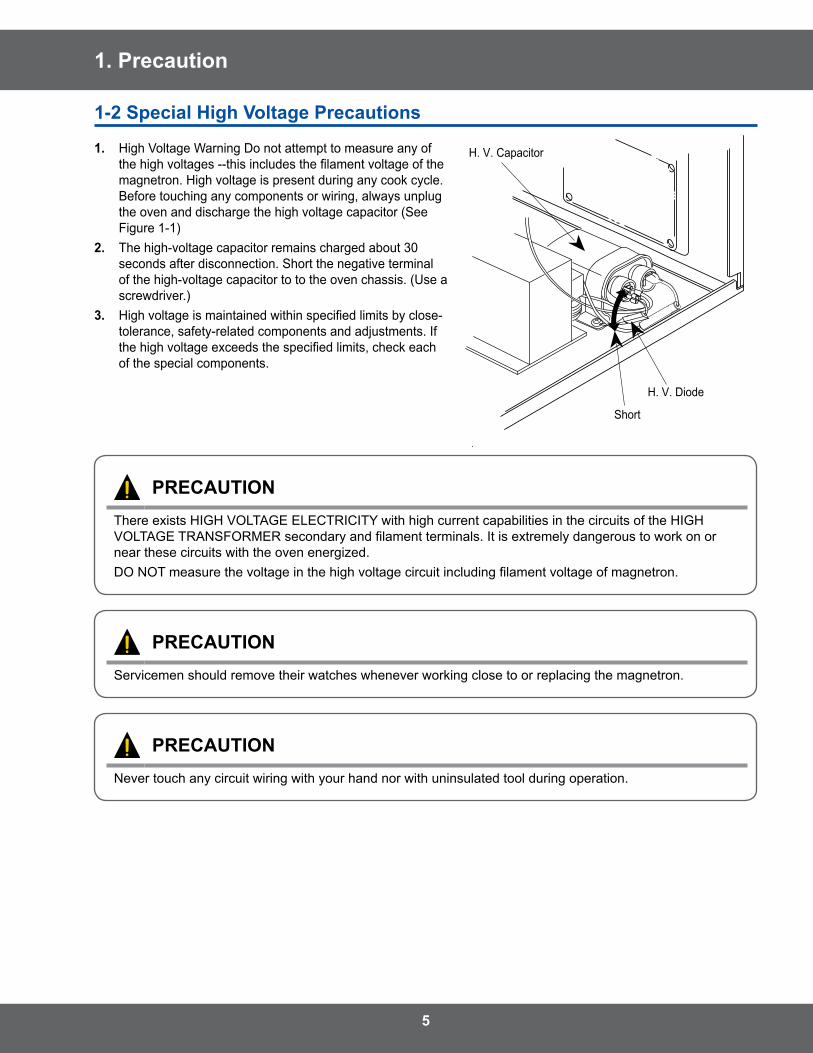
1. Precaution
1-� Special High Voltage Precautions
1. High Voltage Warning Do not attempt to measure any of the high voltages --this includes the filament voltage of the magnetron . High voltage is present during any cook cycle . Before touching any components or wiring, always unplug the oven and discharge the high voltage capacitor (See Figure 1-1)
�. The high-voltage capacitor remains charged about 30 seconds after disconnection . Short the negative terminal of the high-voltage capacitor to to the oven chassis . (Use a screwdriver .)
3. High voltage is maintained within specified limits by close-tolerance, safety-related components and adjustments . If the high voltage exceeds the specified limits, check each of the special components .
H . V . Diode
Short
H . V . Capacitor
PRECAUTIONThere exists HIGH VOLTAGE ELECTRICITY with high current capabilities in the circuits of the HIGH VOLTAGE TRANSFORMER secondary and filament terminals. It is extremely dangerous to work on or near these circuits with the oven energized . DO NOT measure the voltage in the high voltage circuit including filament voltage of magnetron.
PRECAUTIONServicemen should remove their watches whenever working close to or replacing the magnetron .
PRECAUTIONNever touch any circuit wiring with your hand nor with uninsulated tool during operation .
6
2.Specifications
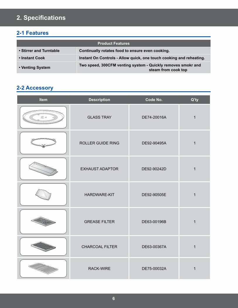
�-1 Features
Product Features
• Stirrer and Turntable Continually rotates food to ensure even cooking.
• Instant Cook Instant On Controls - Allow quick, one touch cooking and reheating.
• Venting System Two speed, 300CFM venting system - Quickly removes smokr and steam from cook top
�-� Accessory
Item Description Code No. Q’ty
GLASS TRAY DE74-20016A 1
ROLLER GUIDE RING DE92-90495A 1
EXHAUST ADAPTOR DE92-90242D 1
HARDWARE-KIT DE92-90505E 1
GREASE FILTER DE63-00196B 1
CHARCOAL FILTER DE63-00367A 1
RACK-WIRE DE75-00032A 1

7
2.Specifications
2-3TableofSpecifications
ItemsBasic Model New Model
SMH8165B/XAC (00,01) SMH8165W/XAC (00,01)Cavity Size (cu .ft .) 1 .6 1 .6PowerPower Source 120 V / 60 Hz 120 V / 60 HzOutput Power (Watts) 950 950Power Consumption (Watts/Amp) 1500 1500CharacteristicsControl Method Touch TouchDisplay VFD 1LINE VFD 1LINESensor Yes YesCooking Timer 99 min . 99 sec . 99 min . 99 sec .Power Level 10 10Auto Defrost Yes YesAuto Reheat Yes YesOne Touch Instant Cook Pads Yes YesHandy Helper Yes YesKids’ Meals Yes YesSnack bar Yes YesMore/Less Yes YesCooking Stages 3 3One Minute Plus Yes YesClock Yes YesKitchen Timer Yes YesWeight Option Kg KgReminder End Signal On/Off No NoChild Safety Lock No NoClock System Option (12 hrs / 24 hrs) 12 hrs 12 hrsDemonstration Mode No NoNumeric Pads 0-9 0-9Turntable Distribution Stirrer + Turntable Stirrer + TurntableTurntable On/Off No NoEnd Signal Sound Yes YesVent Fan CFM 300 300Vent Orientation Vertical VerticalVent Fan Control Hi/Lo/Off Hi/Lo/OffCooktop Lighting Hi/Lo/Off Hi/Lo/Off
Cabinet Colour STSS/Black/White STSS/Black/WhiteCavity Interior Epoxy EpoxyCabinet Dimensions W x H x D (inches) 29 7/8 x 16 1/2 x 15 1/16 29 7/8 x 16 1/2 x 15 1/16
Net Weight (lb) STSS: 52 .9 lbs / Plastic: 52 .2 lbs STSS: 52 .9 lbs / Plastic: 52 .2 lbs
Shipping PropertiesShipping Dimensions W x H x D (inches) 33 3/8 x 19 15/16 x 19 13/32 33 3/8 x 19 15/16 x 19 13/32Loading Q’ty (sets / 40ft) 330 (Jumbo) 330 (Jumbo)Shipping Weight (lb) 60 .2 lbs 60 .2 lbs
8
3. Disassembly and Reassembly
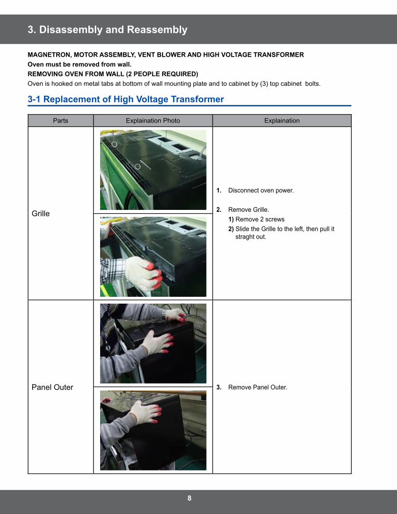
MAGNETRON, MOTOR ASSEMBLY, VENT BLOWER AND HIGH VOLTAGE TRANSFORMEROven must be removed from wall.REMOVING OVEN FROM WALL (� PEOPLE REQUIRED)Oven is hooked on metal tabs at bottom of wall mounting plate and to cabinet by (3) top cabinet bolts .
3-1 Replacement of High Voltage Transformer
Parts Explaination Photo Explaination
Grille
1. Disconnect oven power .
�. Remove Grille . 1) Remove 2 screws �) Slide the Grille to the left, then pull it
straght out .
Panel Outer 3. Remove Panel Outer .
9
3. Disassembly and Reassembly
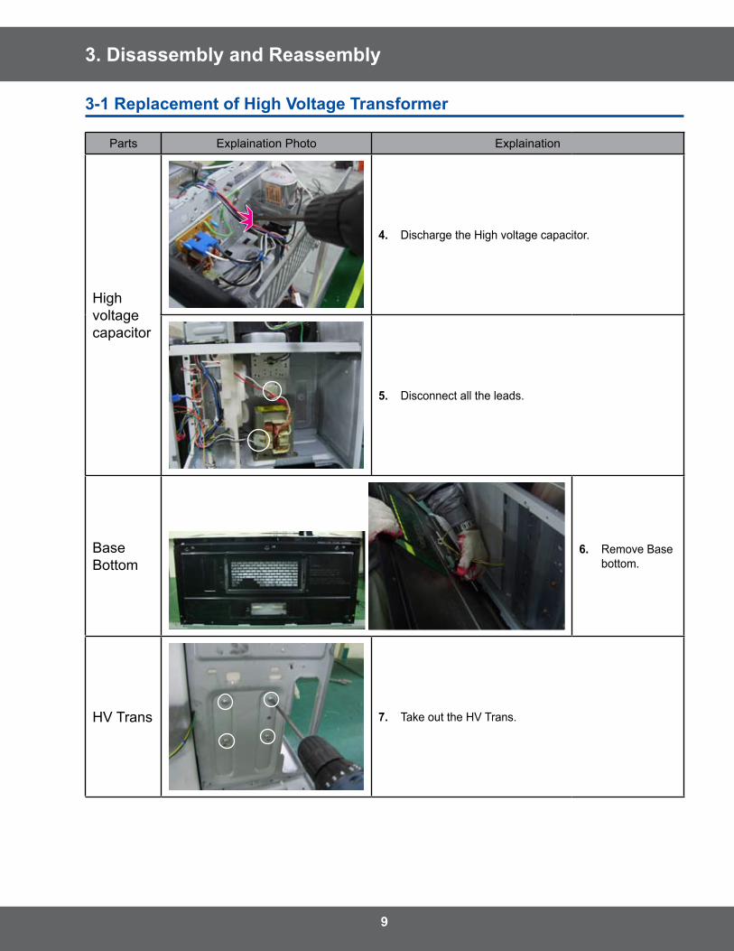
3-1 Replacement of High Voltage Transformer
Parts Explaination Photo Explaination
High voltage capacitor
4. Discharge the High voltage capacitor .
5. Disconnect all the leads .
Base Bottom
6. Remove Base bottom .
HV Trans 7. Take out the HV Trans .
10
3. Disassembly and Reassembly
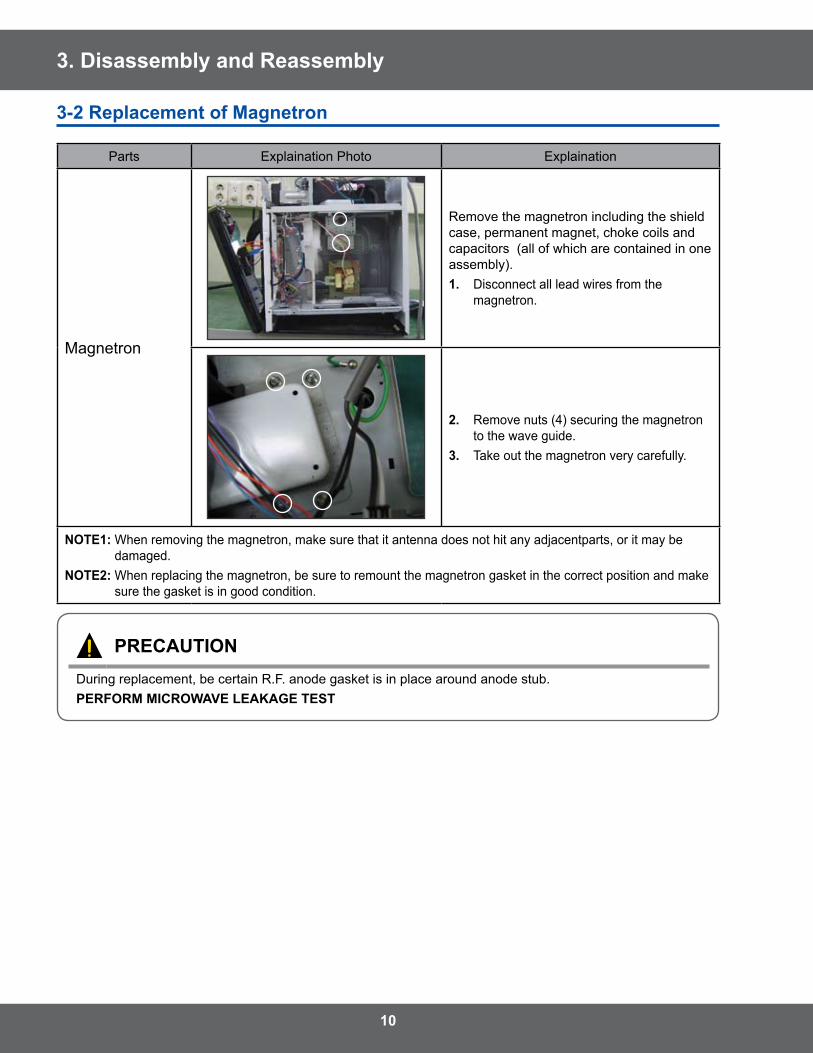
3-� Replacement of Magnetron
Parts Explaination Photo Explaination
Magnetron
Remove the magnetron including the shield case, permanent magnet, choke coils and capacitors (all of which are contained in one assembly) .1. Disconnect all lead wires from the
magnetron .
�. Remove nuts (4) securing the magnetron to the wave guide .
3. Take out the magnetron very carefully .
NOTE1: When removing the magnetron, make sure that it antenna does not hit any adjacentparts, or it may be damaged .
NOTE�: When replacing the magnetron, be sure to remount the magnetron gasket in the correct position and make sure the gasket is in good condition .
PRECAUTIONDuring replacement, be certain R .F . anode gasket is in place around anode stub .PERFORM MICROWAVE LEAKAGE TEST
11
3. Disassembly and Reassembly
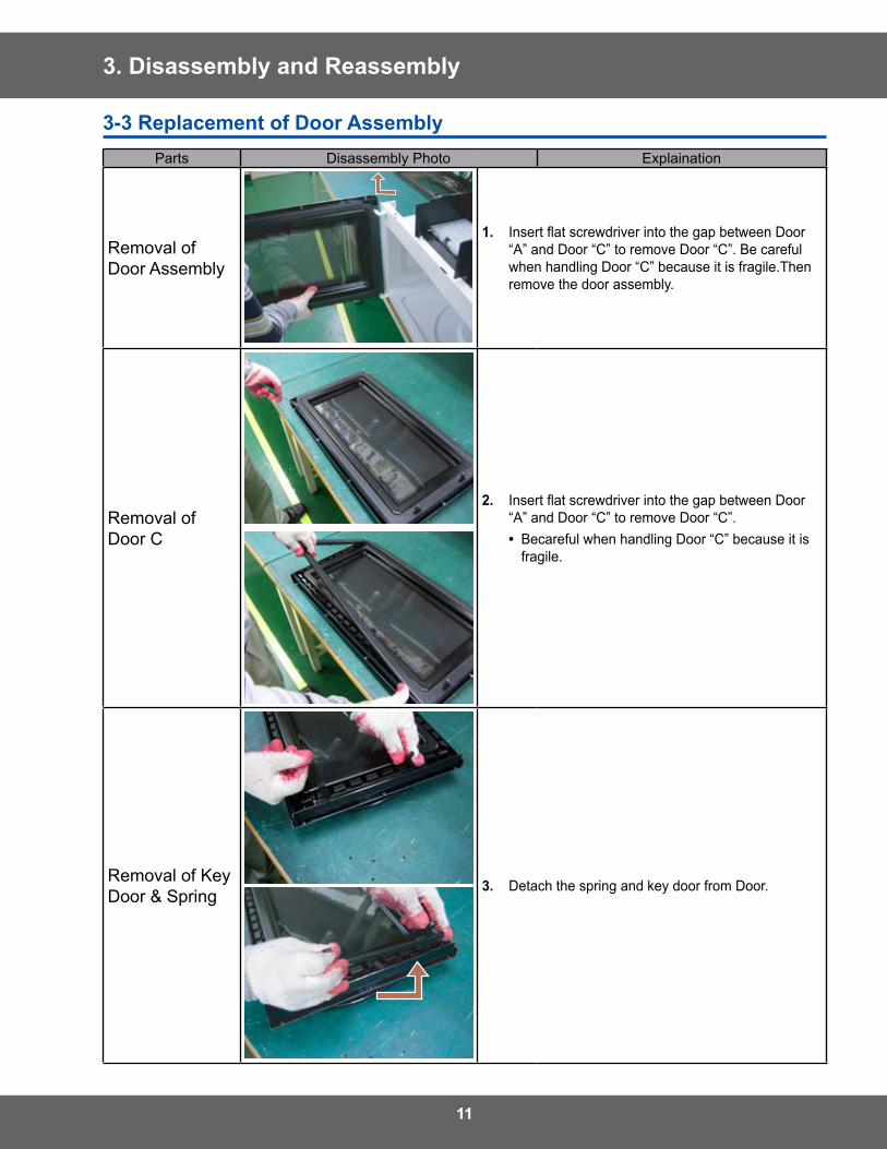
3-3 Replacement of Door AssemblyParts Disassembly Photo Explaination
Removal of Door Assembly
1. Insert flat screwdriver into the gap between Door “A” and Door “C” to remove Door “C” . Be careful when handling Door “C” because it is fragile .Then remove the door assembly .
Removal of Door C
�. Insert flat screwdriver into the gap between Door “A” and Door “C” to remove Door “C” .
• Becareful when handling Door “C” because it is fragile .
Removal of Key Door & Spring 3. Detach the spring and key door from Door .
1�
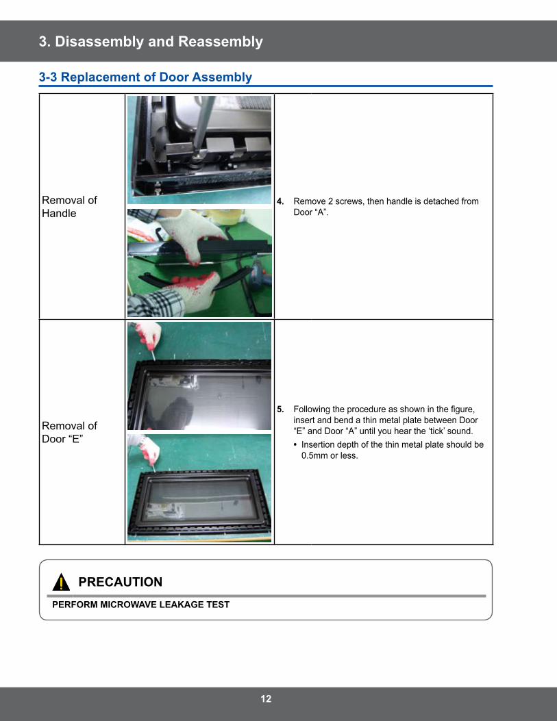
3. Disassembly and Reassembly
Removal of Handle
4. Remove 2 screws, then handle is detached from Door “A” .
Removal of Door “E”
5. Following the procedure as shown in the figure, insert and bend a thin metal plate between Door “E” and Door “A” until you hear the ‘tick’ sound .
• Insertion depth of the thin metal plate should be 0 .5mm or less .
PRECAUTIONPERFORM MICROWAVE LEAKAGE TEST
3-3 Replacement of Door Assembly
13
3. Disassembly and Reassembly
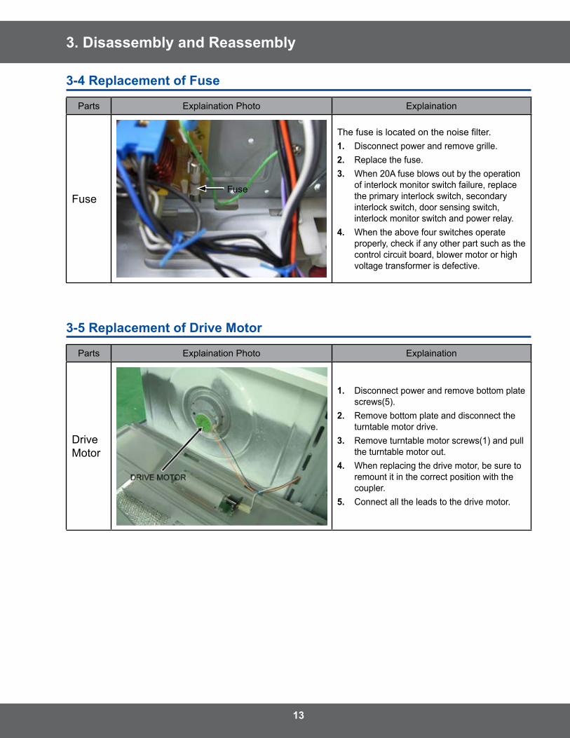
3-4 Replacement of Fuse
Parts Explaination Photo Explaination
Fuse
The fuse is located on the noise filter.1. Disconnect power and remove grille .�. Replace the fuse .3. When 20A fuse blows out by the operation
of interlock monitor switch failure, replace the primary interlock switch, secondary interlock switch, door sensing switch, interlock monitor switch and power relay .
4. When the above four switches operate properly, check if any other part such as the control circuit board, blower motor or high voltage transformer is defective .
3-5 Replacement of Drive Motor
Parts Explaination Photo Explaination
Drive Motor
1. Disconnect power and remove bottom plate screws(5) .
�. Remove bottom plate and disconnect the turntable motor drive .
3. Remove turntable motor screws(1) and pull the turntable motor out .
4. When replacing the drive motor, be sure to remount it in the correct position with the coupler .
5. Connect all the leads to the drive motor .
Fuse
14
3. Disassembly and Reassembly
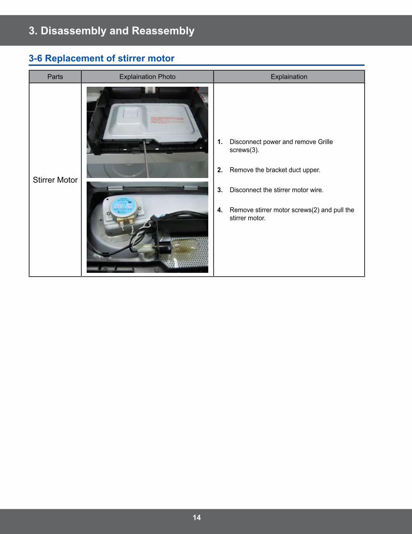
3-6 Replacement of stirrer motor
Parts Explaination Photo Explaination
Stirrer Motor
1. Disconnect power and remove Grille screws(3) .
�. Remove the bracket duct upper .
3. Disconnect the stirrer motor wire .
4. Remove stirrer motor screws(2) and pull the stirrer motor .
15
3. Disassembly and Reassembly
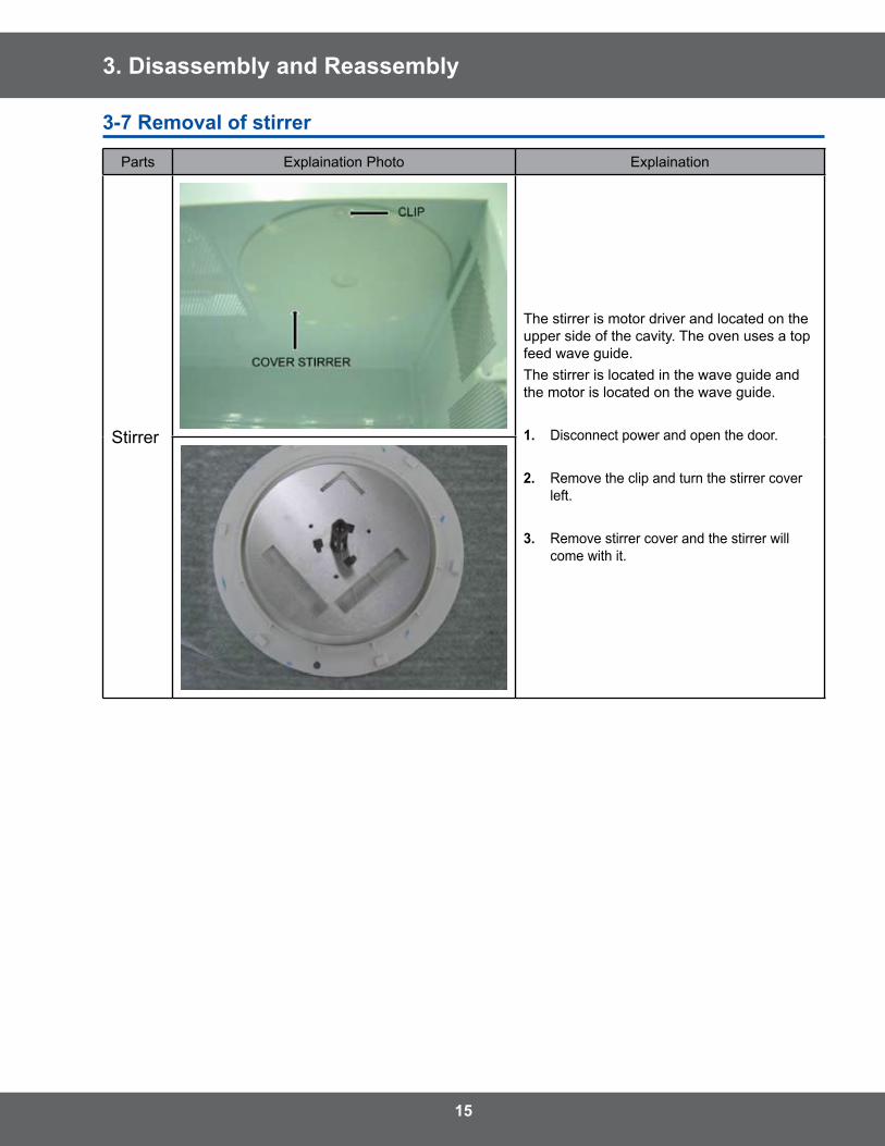
3-7 Removal of stirrer
Parts Explaination Photo Explaination
Stirrer
The stirrer is motor driver and located on the upper side of the cavity . The oven uses a top feed wave guide . The stirrer is located in the wave guide and the motor is located on the wave guide .
1. Disconnect power and open the door .
�. Remove the clip and turn the stirrer cover left .
3. Remove stirrer cover and the stirrer will come with it .
16
3. Disassembly and Reassembly
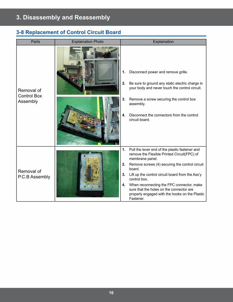
3-8 Replacement of Control Circuit BoardParts Explaination Photo Explaination
Removal of Control Box Assembly
1. Disconnect power and remove grille .
�. Be sure to ground any static electric charge in your body and never touch the control circuit .
3. Remove a screw securing the control box assembly .
4. Disconnect the connectors from the control circuit board .
Removal of P .C .B Assembly
1. Pull the lever end of the plastic fastener and remove the Flexible Printed Circuit(FPC) of membrane panel .
�. Remove screws (4) securing the control circuit board .
3. Lift up the control circuit board from the Ass’y control box .
4. When reconnecting the FPC connector, make sure that the holes on the connector are properly engaged with the hooks on the Plastic Fastener .
17
3. Disassembly and Reassembly
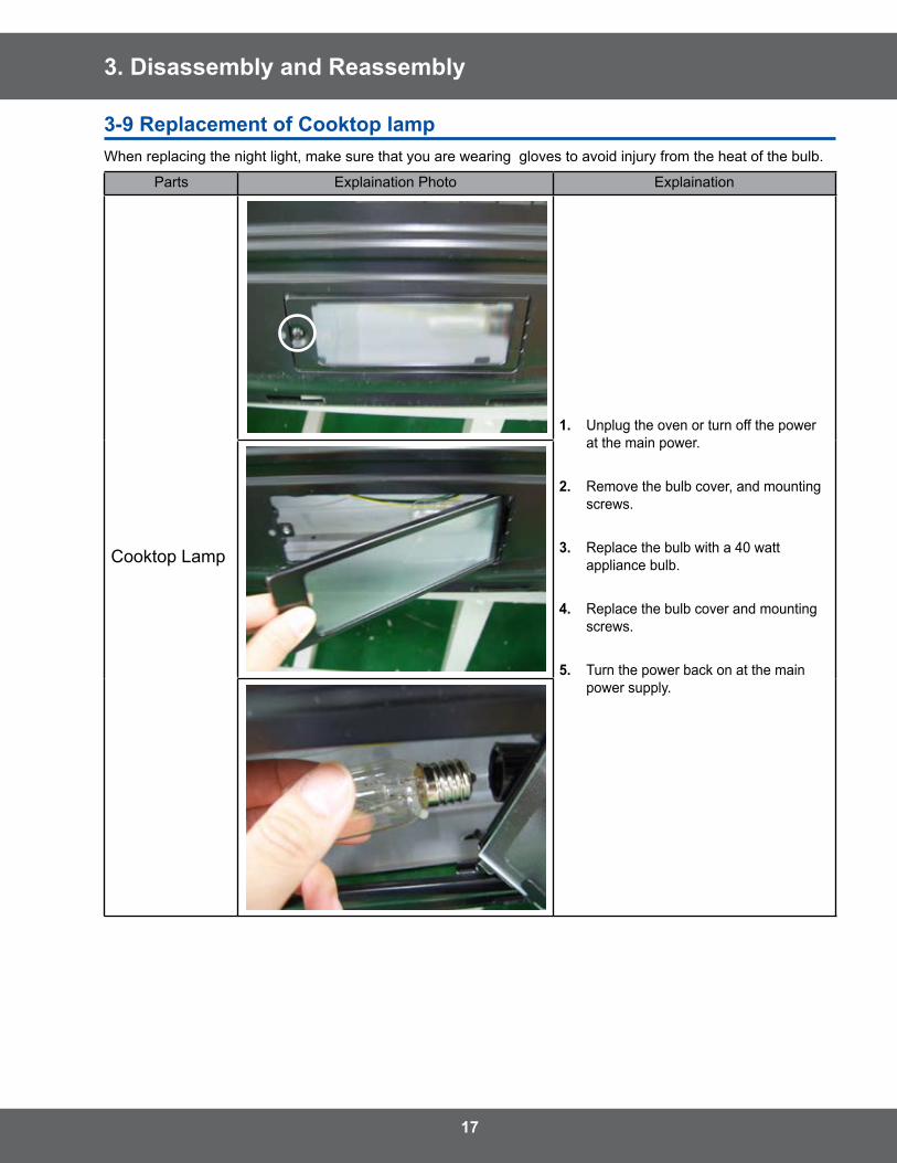
3-9 Replacement of Cooktop lampWhen replacing the night light, make sure that you are wearing gloves to avoid injury from the heat of the bulb .
Parts Explaination Photo Explaination
Cooktop Lamp
1. Unplug the oven or turn off the power at the main power .
�. Remove the bulb cover, and mounting screws .
3. Replace the bulb with a 40 watt appliance bulb .
4. Replace the bulb cover and mounting screws .
5. Turn the power back on at the main power supply .
18
3. Disassembly and Reassembly
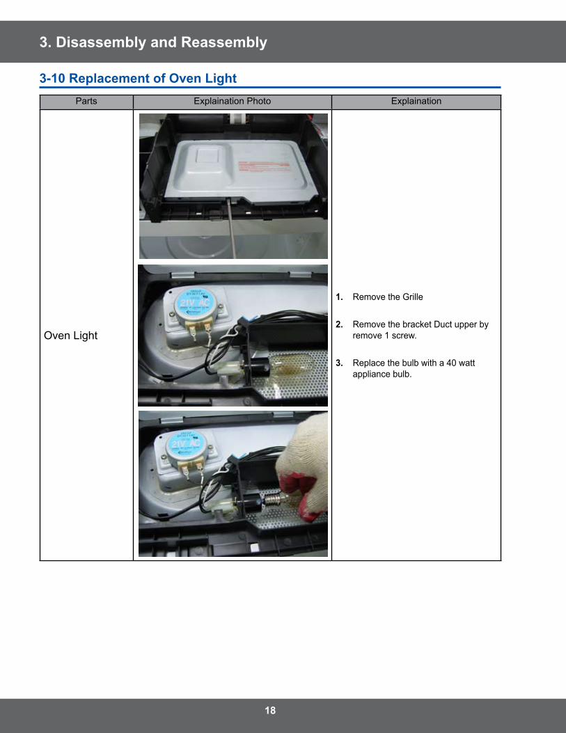
3-10 Replacement of Oven LightParts Explaination Photo Explaination
Oven Light
1. Remove the Grille
�. Remove the bracket Duct upper by remove 1 screw .
3. Replace the bulb with a 40 watt appliance bulb .
19
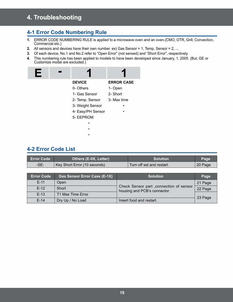
4. Troubleshooting
4-1 Error Code Numbering Rule1. ERROR CODE NUMBERING RULE is applied to a microwave oven and an oven .(CMO, OTR, Grill, Convection,
Commercial etc .)�. All sensors and devices have their own number . ex) Gas Sensor = 1, Temp . Sensor = 2, . . .3. Of each device, No .1 and No .2 refer to “Open Error” (not sensed) and “Short Error”, respectively .4. This numbering rule has been applied to models to have been developed since January, 1, 2005 . (But, GE or
Customize model are excluded .)
DEVICE ERROR CASE0- Others 1- Open1- Gas Sensor 2- Short2- Temp . Sensor 3- Max time3- Weight Sensor •4- Easy/PH Sensor •5- EEPROM
•••
4-� Error Code List
Error Code Others (E-0X, Letter) Solution Page-SE- Key Short Error (10 seconds) Turn off set and restart . 20 Page
Error Code Gas Sensor Error Case (E-1X) Solution PageE-11 Open
Check Sensor part ,connection of sensor housing and PCB’s connector .
21 PageE-12 Short 22 PageE-13 T1 Max Time Error
23 PageE-14 Dry Up / No Load Insert food and restart .
4. Troubleshooting
�0
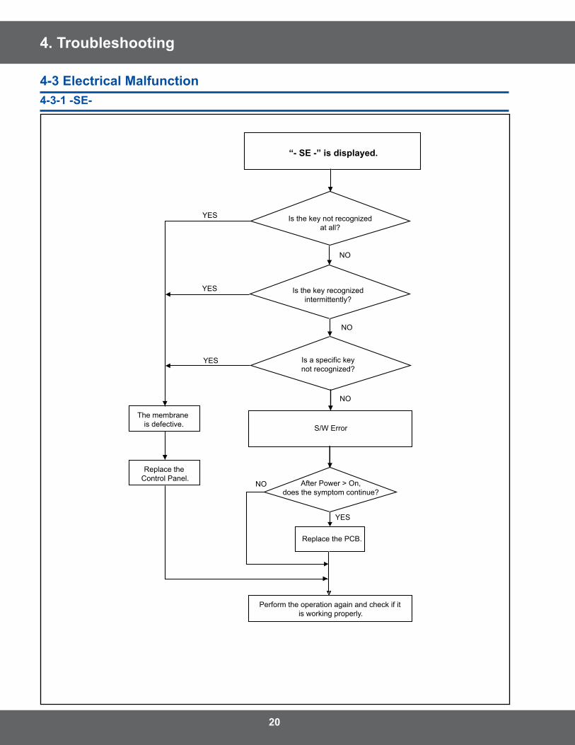
4. Troubleshooting
YES
NO
YES
NO
NO
YES
YES
NO
“- SE -” is displayed.
Perform the operation again and check if it is working properly.
S/W Error
Is a specific keynot recognized?
Is the key recognizedintermittently?
The membrane is defective.
Replace the Control Panel.
Is the key not recognizedat all?
After Power > On,does the symptom continue?
Replace the PCB.
4-3 Electrical Malfunction4-3-1 -SE-
�1
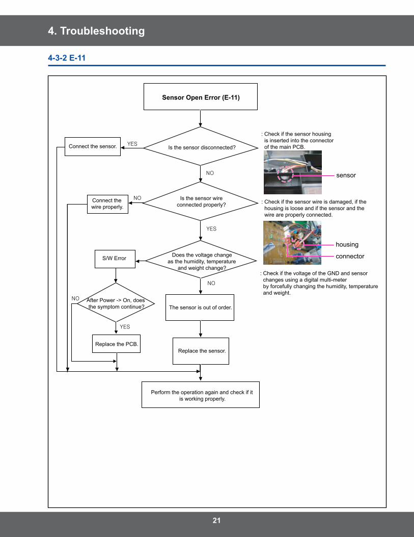
4. Troubleshooting
YES
NO
NO
YES
NO
YES
NO
Sensor Open Error (E-11)
Perform the operation again and check if it is working properly.
: Check if the sensor housing is inserted into the connector of the main PCB.
The sensor is out of order.
Is the sensor disconnected?
Is the sensor wireconnected properly?
Does the voltage changeas the humidity, temperature
and weight change?
Replace the sensor.
: Check if the sensor wire is damaged, if the housing is loose and if the sensor and the wire are properly connected.
: Check if the voltage of the GND and sensor changes using a digital multi-meter by forcefully changing the humidity, temperature and weight.
Connect the sensor.
Connect the wire properly.
S/W Error
After Power -> On, does the symptom continue?
Replace the PCB.
sensor
housing
connector
4-3-� E-11
��
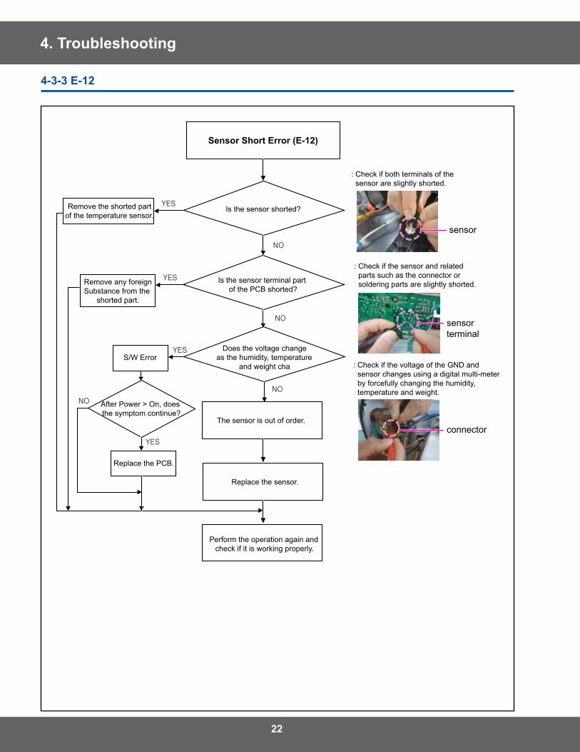
4. Troubleshooting
: Check if both terminals of the sensor are slightly shorted.
Does the voltage changeas the humidity, temperature
and weight cha
Is the sensor terminal part of the PCB shorted?
: Check if the voltage of the GND and sensor changes using a digital multi-meter by forcefully changing the humidity, temperature and weight.
: Check if the sensor and related parts such as the connector or soldering parts are slightly shorted.
Remove the shorted partof the temperature sensor.
Remove any foreignSubstance from the
shorted part.
YES
NO
YES
YES
NO
NO
YES
NO
Sensor Short Error (E-12)
Is the sensor shorted?
The sensor is out of order.
Replace the sensor.
Perform the operation again and check if it is working properly.
S/W Error
After Power > On, does the symptom continue?
Replace the PCB.
sensor
sensorterminal
connector
4-3-3 E-1�
�3
4. Troubleshooting
YES
NO
YES
NO
NO
YES
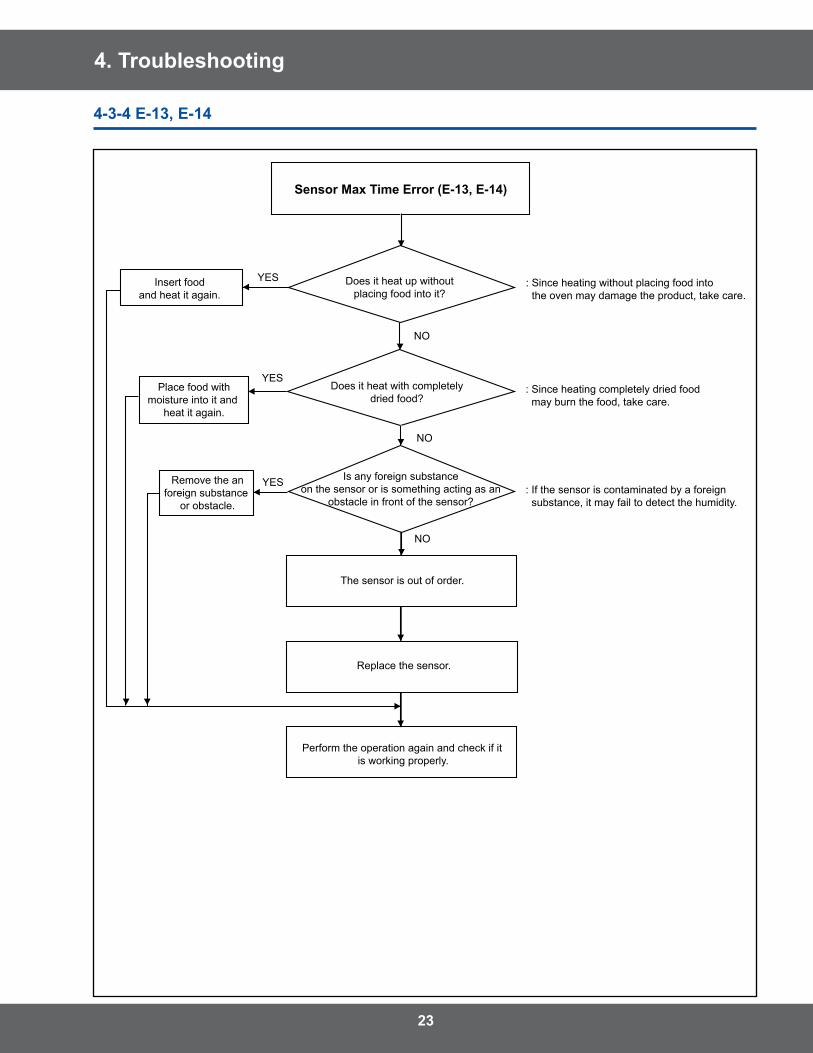
Sensor Max Time Error (E-13, E-14)
Perform the operation again and check if it is working properly.
: Since heating without placing food into the oven may damage the product, take care.
The sensor is out of order.
Is any foreign substanceon the sensor or is something acting as an
obstacle in front of the sensor?
Does it heat with completelydried food?
Replace the sensor.
: If the sensor is contaminated by a foreign substance, it may fail to detect the humidity.
: Since heating completely dried food may burn the food, take care.
Insert foodand heat it again.
Place food withmoisture into it and
heat it again.
Remove the anforeign substance
or obstacle.
Does it heat up withoutplacing food into it?
4-3-4 E-13, E-14
�4
4. Troubleshooting
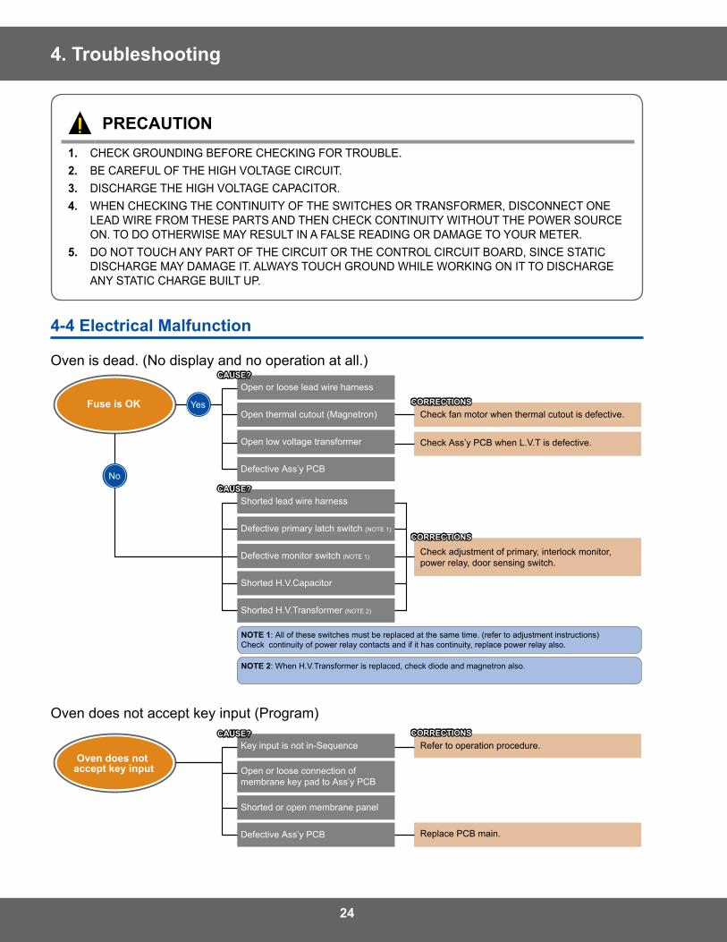
PRECAUTION1. CHECK GROUNDING BEFORE CHECKING FOR TROUBLE .�. BE CAREFUL OF THE HIGH VOLTAGE CIRCUIT .3. DISCHARGE THE HIGH VOLTAGE CAPACITOR .4. WHEN CHECKING THE CONTINUITY OF THE SWITCHES OR TRANSFORMER, DISCONNECT ONE
LEAD WIRE FROM THESE PARTS AND THEN CHECK CONTINUITY WITHOUT THE POWER SOURCE ON . TO DO OTHERWISE MAY RESULT IN A FALSE READING OR DAMAGE TO YOUR METER .
5. DO NOT TOUCH ANY PART OF THE CIRCUIT OR THE CONTROL CIRCUIT BOARD, SINCE STATIC DISCHARGE MAY DAMAGE IT . ALWAYS TOUCH GROUND WHILE WORKING ON IT TO DISCHARGE ANY STATIC CHARGE BUILT UP .
4-4 Electrical Malfunction
Oven is dead . (No display and no operation at all .)
Fuse is OKOpen or loose lead wire harness
Open thermal cutout (Magnetron)
Open low voltage transformer
Check fan motor when thermal cutout is defective.
Check Ass’y PCB when L.V.T is defective.
Check adjustment of primary, interlock monitor, power relay, door sensing switch.
NOTE 1: All of these switches must be replaced at the same time. (refer to adjustment instructions) Check continuity of power relay contacts and if it has continuity, replace power relay also.
NOTE: Large contact resistance will bring lower magnetron filament voltage and cause magnetron to lower output and/or intermittent oscillation.
NOTE 2: When H.V.Transformer is replaced, check diode and magnetron also.
Defective Ass’y PCB
Shorted lead wire harness
Defective primary latch switch (NOTE 1)
Defective monitor switch (NOTE 1)
Shorted H.V.Capacitor
Shorted H.V.Transformer (NOTE 2)
Oven does not accept key input
Key input is not in-Sequence
Open or loose connection of membrane key pad to Ass’y PCB
Shorted or open membrane panel
Refer to operation procedure.
Replace PCB main.Defective Ass’y PCB
Timer starts countdown but no microwave
oscillation
Off-alignment of latch switches
Open or loose connection of high voltage circuit especially magnetron filament circuit (NOTE)
Defective high voltage components H.V.Transformer H.V. Capacitor H.V.Diode, H.V.Fuse Magnetron
Adjust door and latch switches.
Check high voltage component according tocomponent test procedure and replace if it isdefective.
Open or loose wiring of power relay
Replace PCB main.
Defective primary latch switch
Defective power relay or Ass’y PCB
Oven does not accept key input (Program)
Fuse is OKOpen or loose lead wire harness
Open thermal cutout (Magnetron)
Open low voltage transformer
Check fan motor when thermal cutout is defective.
Check Ass’y PCB when L.V.T is defective.
Check adjustment of primary, interlock monitor, power relay, door sensing switch.
NOTE 1: All of these switches must be replaced at the same time. (refer to adjustment instructions) Check continuity of power relay contacts and if it has continuity, replace power relay also.
NOTE: Large contact resistance will bring lower magnetron filament voltage and cause magnetron to lower output and/or intermittent oscillation.
NOTE 2: When H.V.Transformer is replaced, check diode and magnetron also.
Defective Ass’y PCB
Shorted lead wire harness
Defective primary latch switch (NOTE 1)
Defective monitor switch (NOTE 1)
Shorted H.V.Capacitor
Shorted H.V.Transformer (NOTE 2)
Oven does not accept key input
Key input is not in-Sequence
Open or loose connection of membrane key pad to Ass’y PCB
Shorted or open membrane panel
Refer to operation procedure.
Replace PCB main.Defective Ass’y PCB
Timer starts countdown but no microwave
oscillation
Off-alignment of latch switches
Open or loose connection of high voltage circuit especially magnetron filament circuit (NOTE)
Defective high voltage components H.V.Transformer H.V. Capacitor H.V.Diode, H.V.Fuse Magnetron
Adjust door and latch switches.
Check high voltage component according tocomponent test procedure and replace if it isdefective.
Open or loose wiring of power relay
Replace PCB main.
Defective primary latch switch
Defective power relay or Ass’y PCB
�5
4. Troubleshooting
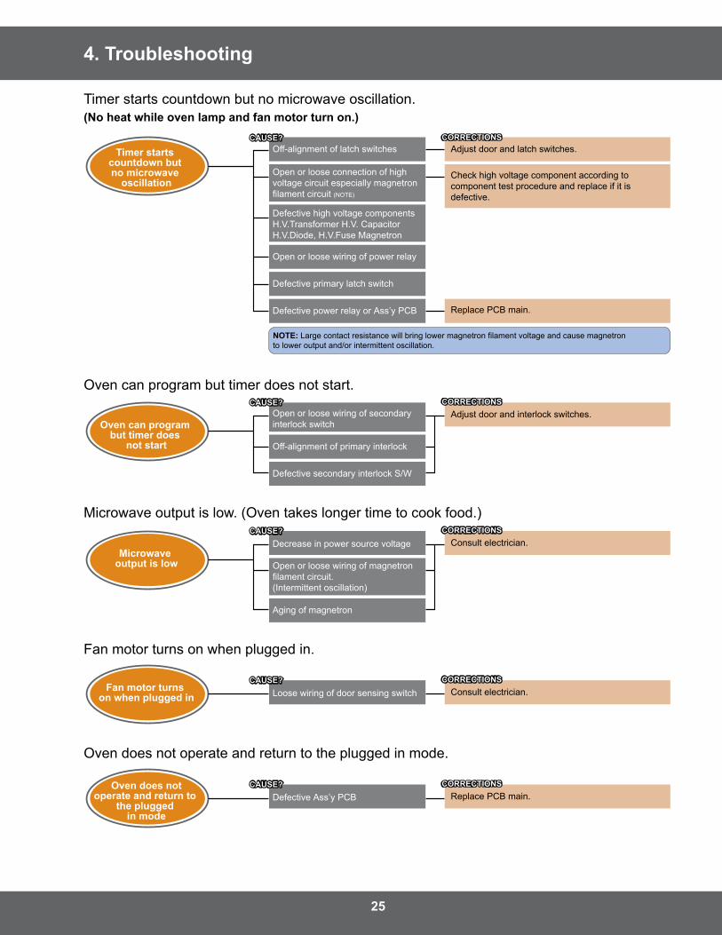
Timer starts countdown but no microwave oscillation .(No heat while oven lamp and fan motor turn on.)
Fuse is OKOpen or loose lead wire harness
Open thermal cutout (Magnetron)
Open low voltage transformer
Check fan motor when thermal cutout is defective.
Check Ass’y PCB when L.V.T is defective.
Check adjustment of primary, interlock monitor, power relay, door sensing switch.
NOTE 1: All of these switches must be replaced at the same time. (refer to adjustment instructions) Check continuity of power relay contacts and if it has continuity, replace power relay also.
NOTE: Large contact resistance will bring lower magnetron filament voltage and cause magnetron to lower output and/or intermittent oscillation.
NOTE 2: When H.V.Transformer is replaced, check diode and magnetron also.
Defective Ass’y PCB
Shorted lead wire harness
Defective primary latch switch (NOTE 1)
Defective monitor switch (NOTE 1)
Shorted H.V.Capacitor
Shorted H.V.Transformer (NOTE 2)
Oven does not accept key input
Key input is not in-Sequence
Open or loose connection of membrane key pad to Ass’y PCB
Shorted or open membrane panel
Refer to operation procedure.
Replace PCB main.Defective Ass’y PCB
Timer starts countdown but no microwave
oscillation
Off-alignment of latch switches
Open or loose connection of high voltage circuit especially magnetron filament circuit (NOTE)
Defective high voltage components H.V.Transformer H.V. Capacitor H.V.Diode, H.V.Fuse Magnetron
Adjust door and latch switches.
Check high voltage component according tocomponent test procedure and replace if it isdefective.
Open or loose wiring of power relay
Replace PCB main.
Defective primary latch switch
Defective power relay or Ass’y PCB
Oven can program but timer does not start .
Oven can program but timer does
not start
Open or loose wiring of secondary interlock switch
Adjust door and interlock switches.
Off-alignment of primary interlock
Defective secondary interlock S/W
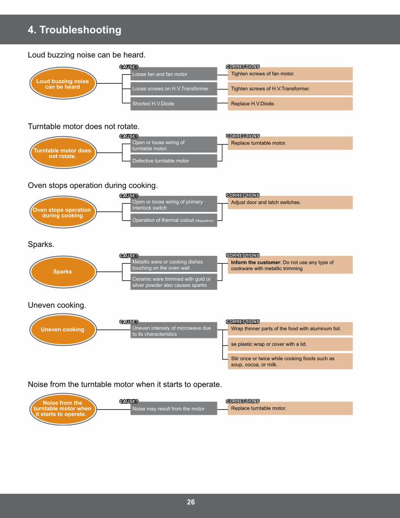
Turntable motor doesnot rotate.
Open or loose wiring of turntable motor.
Replace turntable motor.
Defective turntable motor
Oven stops operation during cooking
Open or loose wiring of primary interlock switch
Adjust door and latch switches.
Operation of thermal cutout (Magnetron)
Sparks
Metallic ware or cooking dishes touching on the oven wall
Inform the customer: Do not use any type of cookware with metallic trimming
Ceramic ware trimmed with gold or silver powder also causes sparks
Loud buzzing noisecan be heard
Loose fan and fan motor Tighten screws of fan motor.
Tighten screws of H.V.Transformer.
Replace H.V.Diode.
Loose screws on H.V.Transformer
Shorted H.V.Diode
Microwave output is low
Decrease in power source voltage Consult electrician.
Open or loose wiring of magnetron filament circuit. (Intermittent oscillation)
Aging of magnetron
Fan motor turns on when plugged in Loose wiring of door sensing switch Consult electrician.
Oven does notoperate and return to
the plugged in mode
Defective Ass’y PCB Replace PCB main.
Noise from theturntable motor whenit starts to operate.
Noise may result from the motor Replace turntable motor.
Uneven cooking Uneven intensity of microwave due to its characteristics
Wrap thinner parts of the food with aluminum foil.
se plastic wrap or cover with a lid.
Stir once or twice while cooking foods such as soup, cocoa, or milk.
Microwave output is low . (Oven takes longer time to cook food .)
Oven can program but timer does
not start
Open or loose wiring of secondary interlock switch
Adjust door and interlock switches.
Off-alignment of primary interlock
Defective secondary interlock S/W
Turntable motor doesnot rotate.
Open or loose wiring of turntable motor.
Replace turntable motor.
Defective turntable motor
Oven stops operation during cooking
Open or loose wiring of primary interlock switch
Adjust door and latch switches.
Operation of thermal cutout (Magnetron)
Sparks
Metallic ware or cooking dishes touching on the oven wall
Inform the customer: Do not use any type of cookware with metallic trimming
Ceramic ware trimmed with gold or silver powder also causes sparks
Loud buzzing noisecan be heard
Loose fan and fan motor Tighten screws of fan motor.
Tighten screws of H.V.Transformer.
Replace H.V.Diode.
Loose screws on H.V.Transformer
Shorted H.V.Diode
Microwave output is low
Decrease in power source voltage Consult electrician.
Open or loose wiring of magnetron filament circuit. (Intermittent oscillation)
Aging of magnetron
Fan motor turns on when plugged in Loose wiring of door sensing switch Consult electrician.
Oven does notoperate and return to
the plugged in mode
Defective Ass’y PCB Replace PCB main.
Noise from theturntable motor whenit starts to operate.
Noise may result from the motor Replace turntable motor.
Uneven cooking Uneven intensity of microwave due to its characteristics
Wrap thinner parts of the food with aluminum foil.
se plastic wrap or cover with a lid.
Stir once or twice while cooking foods such as soup, cocoa, or milk.
Fan motor turns on when plugged in .
Oven can program but timer does
not start
Open or loose wiring of secondary interlock switch
Adjust door and interlock switches.
Off-alignment of primary interlock
Defective secondary interlock S/W
Turntable motor doesnot rotate.
Open or loose wiring of turntable motor.
Replace turntable motor.
Defective turntable motor
Oven stops operation during cooking
Open or loose wiring of primary interlock switch
Adjust door and latch switches.
Operation of thermal cutout (Magnetron)
Sparks
Metallic ware or cooking dishes touching on the oven wall
Inform the customer: Do not use any type of cookware with metallic trimming
Ceramic ware trimmed with gold or silver powder also causes sparks
Loud buzzing noisecan be heard
Loose fan and fan motor Tighten screws of fan motor.
Tighten screws of H.V.Transformer.
Replace H.V.Diode.
Loose screws on H.V.Transformer
Shorted H.V.Diode
Microwave output is low
Decrease in power source voltage Consult electrician.
Open or loose wiring of magnetron filament circuit. (Intermittent oscillation)
Aging of magnetron
Fan motor turns on when plugged in Loose wiring of door sensing switch Consult electrician.
Oven does notoperate and return to
the plugged in mode
Defective Ass’y PCB Replace PCB main.
Noise from theturntable motor whenit starts to operate.
Noise may result from the motor Replace turntable motor.
Uneven cooking Uneven intensity of microwave due to its characteristics
Wrap thinner parts of the food with aluminum foil.
se plastic wrap or cover with a lid.
Stir once or twice while cooking foods such as soup, cocoa, or milk.
Oven does not operate and return to the plugged in mode .
Oven can program but timer does
not start
Open or loose wiring of secondary interlock switch
Adjust door and interlock switches.
Off-alignment of primary interlock
Defective secondary interlock S/W
Turntable motor doesnot rotate.
Open or loose wiring of turntable motor.
Replace turntable motor.
Defective turntable motor
Oven stops operation during cooking
Open or loose wiring of primary interlock switch
Adjust door and latch switches.
Operation of thermal cutout (Magnetron)
Sparks
Metallic ware or cooking dishes touching on the oven wall
Inform the customer: Do not use any type of cookware with metallic trimming
Ceramic ware trimmed with gold or silver powder also causes sparks
Loud buzzing noisecan be heard
Loose fan and fan motor Tighten screws of fan motor.
Tighten screws of H.V.Transformer.
Replace H.V.Diode.
Loose screws on H.V.Transformer
Shorted H.V.Diode
Microwave output is low
Decrease in power source voltage Consult electrician.
Open or loose wiring of magnetron filament circuit. (Intermittent oscillation)
Aging of magnetron
Fan motor turns on when plugged in Loose wiring of door sensing switch Consult electrician.
Oven does notoperate and return to
the plugged in mode
Defective Ass’y PCB Replace PCB main.
Noise from theturntable motor whenit starts to operate.
Noise may result from the motor Replace turntable motor.
Uneven cooking Uneven intensity of microwave due to its characteristics
Wrap thinner parts of the food with aluminum foil.
se plastic wrap or cover with a lid.
Stir once or twice while cooking foods such as soup, cocoa, or milk.
�6
4. Troubleshooting
Loud buzzing noise can be heard .
Oven can program but timer does
not start
Open or loose wiring of secondary interlock switch
Adjust door and interlock switches.
Off-alignment of primary interlock
Defective secondary interlock S/W
Turntable motor doesnot rotate.
Open or loose wiring of turntable motor.
Replace turntable motor.
Defective turntable motor
Oven stops operation during cooking
Open or loose wiring of primary interlock switch
Adjust door and latch switches.
Operation of thermal cutout (Magnetron)
Sparks
Metallic ware or cooking dishes touching on the oven wall
Inform the customer: Do not use any type of cookware with metallic trimming
Ceramic ware trimmed with gold or silver powder also causes sparks
Loud buzzing noisecan be heard
Loose fan and fan motor Tighten screws of fan motor.
Tighten screws of H.V.Transformer.
Replace H.V.Diode.
Loose screws on H.V.Transformer
Shorted H.V.Diode
Microwave output is low
Decrease in power source voltage Consult electrician.
Open or loose wiring of magnetron filament circuit. (Intermittent oscillation)
Aging of magnetron
Fan motor turns on when plugged in Loose wiring of door sensing switch Consult electrician.
Oven does notoperate and return to
the plugged in mode
Defective Ass’y PCB Replace PCB main.
Noise from theturntable motor whenit starts to operate.
Noise may result from the motor Replace turntable motor.
Uneven cooking Uneven intensity of microwave due to its characteristics
Wrap thinner parts of the food with aluminum foil.
se plastic wrap or cover with a lid.
Stir once or twice while cooking foods such as soup, cocoa, or milk.
Turntable motor does not rotate .
Oven can program but timer does
not start
Open or loose wiring of secondary interlock switch
Adjust door and interlock switches.
Off-alignment of primary interlock
Defective secondary interlock S/W
Turntable motor doesnot rotate.
Open or loose wiring of turntable motor.
Replace turntable motor.
Defective turntable motor
Oven stops operation during cooking
Open or loose wiring of primary interlock switch
Adjust door and latch switches.
Operation of thermal cutout (Magnetron)
Sparks
Metallic ware or cooking dishes touching on the oven wall
Inform the customer: Do not use any type of cookware with metallic trimming
Ceramic ware trimmed with gold or silver powder also causes sparks
Loud buzzing noisecan be heard
Loose fan and fan motor Tighten screws of fan motor.
Tighten screws of H.V.Transformer.
Replace H.V.Diode.
Loose screws on H.V.Transformer
Shorted H.V.Diode
Microwave output is low
Decrease in power source voltage Consult electrician.
Open or loose wiring of magnetron filament circuit. (Intermittent oscillation)
Aging of magnetron
Fan motor turns on when plugged in Loose wiring of door sensing switch Consult electrician.
Oven does notoperate and return to
the plugged in mode
Defective Ass’y PCB Replace PCB main.
Noise from theturntable motor whenit starts to operate.
Noise may result from the motor Replace turntable motor.
Uneven cooking Uneven intensity of microwave due to its characteristics
Wrap thinner parts of the food with aluminum foil.
se plastic wrap or cover with a lid.
Stir once or twice while cooking foods such as soup, cocoa, or milk.
Oven stops operation during cooking .
Oven can program but timer does
not start
Open or loose wiring of secondary interlock switch
Adjust door and interlock switches.
Off-alignment of primary interlock
Defective secondary interlock S/W
Turntable motor doesnot rotate.
Open or loose wiring of turntable motor.
Replace turntable motor.
Defective turntable motor
Oven stops operation during cooking
Open or loose wiring of primary interlock switch
Adjust door and latch switches.
Operation of thermal cutout (Magnetron)
Sparks
Metallic ware or cooking dishes touching on the oven wall
Inform the customer: Do not use any type of cookware with metallic trimming
Ceramic ware trimmed with gold or silver powder also causes sparks
Loud buzzing noisecan be heard
Loose fan and fan motor Tighten screws of fan motor.
Tighten screws of H.V.Transformer.
Replace H.V.Diode.
Loose screws on H.V.Transformer
Shorted H.V.Diode
Microwave output is low
Decrease in power source voltage Consult electrician.
Open or loose wiring of magnetron filament circuit. (Intermittent oscillation)
Aging of magnetron
Fan motor turns on when plugged in Loose wiring of door sensing switch Consult electrician.
Oven does notoperate and return to
the plugged in mode
Defective Ass’y PCB Replace PCB main.
Noise from theturntable motor whenit starts to operate.
Noise may result from the motor Replace turntable motor.
Uneven cooking Uneven intensity of microwave due to its characteristics
Wrap thinner parts of the food with aluminum foil.
se plastic wrap or cover with a lid.
Stir once or twice while cooking foods such as soup, cocoa, or milk.
Sparks .
Oven can program but timer does
not start
Open or loose wiring of secondary interlock switch
Adjust door and interlock switches.
Off-alignment of primary interlock
Defective secondary interlock S/W
Turntable motor doesnot rotate.
Open or loose wiring of turntable motor.
Replace turntable motor.
Defective turntable motor
Oven stops operation during cooking
Open or loose wiring of primary interlock switch
Adjust door and latch switches.
Operation of thermal cutout (Magnetron)
Sparks
Metallic ware or cooking dishes touching on the oven wall
Inform the customer: Do not use any type of cookware with metallic trimming
Ceramic ware trimmed with gold or silver powder also causes sparks
Loud buzzing noisecan be heard
Loose fan and fan motor Tighten screws of fan motor.
Tighten screws of H.V.Transformer.
Replace H.V.Diode.
Loose screws on H.V.Transformer
Shorted H.V.Diode
Microwave output is low
Decrease in power source voltage Consult electrician.
Open or loose wiring of magnetron filament circuit. (Intermittent oscillation)
Aging of magnetron
Fan motor turns on when plugged in Loose wiring of door sensing switch Consult electrician.
Oven does notoperate and return to
the plugged in mode
Defective Ass’y PCB Replace PCB main.
Noise from theturntable motor whenit starts to operate.
Noise may result from the motor Replace turntable motor.
Uneven cooking Uneven intensity of microwave due to its characteristics
Wrap thinner parts of the food with aluminum foil.
se plastic wrap or cover with a lid.
Stir once or twice while cooking foods such as soup, cocoa, or milk.
Uneven cooking .
Oven can program but timer does
not start
Open or loose wiring of secondary interlock switch
Adjust door and interlock switches.
Off-alignment of primary interlock
Defective secondary interlock S/W
Turntable motor doesnot rotate.
Open or loose wiring of turntable motor.
Replace turntable motor.
Defective turntable motor
Oven stops operation during cooking
Open or loose wiring of primary interlock switch
Adjust door and latch switches.
Operation of thermal cutout (Magnetron)
Sparks
Metallic ware or cooking dishes touching on the oven wall
Inform the customer: Do not use any type of cookware with metallic trimming
Ceramic ware trimmed with gold or silver powder also causes sparks
Loud buzzing noisecan be heard
Loose fan and fan motor Tighten screws of fan motor.
Tighten screws of H.V.Transformer.
Replace H.V.Diode.
Loose screws on H.V.Transformer
Shorted H.V.Diode
Microwave output is low
Decrease in power source voltage Consult electrician.
Open or loose wiring of magnetron filament circuit. (Intermittent oscillation)
Aging of magnetron
Fan motor turns on when plugged in Loose wiring of door sensing switch Consult electrician.
Oven does notoperate and return to
the plugged in mode
Defective Ass’y PCB Replace PCB main.
Noise from theturntable motor whenit starts to operate.
Noise may result from the motor Replace turntable motor.
Uneven cooking Uneven intensity of microwave due to its characteristics
Wrap thinner parts of the food with aluminum foil.
se plastic wrap or cover with a lid.
Stir once or twice while cooking foods such as soup, cocoa, or milk.
Noise from the turntable motor when it starts to operate .
Oven can program but timer does
not start
Open or loose wiring of secondary interlock switch
Adjust door and interlock switches.
Off-alignment of primary interlock
Defective secondary interlock S/W
Turntable motor doesnot rotate.
Open or loose wiring of turntable motor.
Replace turntable motor.
Defective turntable motor
Oven stops operation during cooking
Open or loose wiring of primary interlock switch
Adjust door and latch switches.
Operation of thermal cutout (Magnetron)
Sparks
Metallic ware or cooking dishes touching on the oven wall
Inform the customer: Do not use any type of cookware with metallic trimming
Ceramic ware trimmed with gold or silver powder also causes sparks
Loud buzzing noisecan be heard
Loose fan and fan motor Tighten screws of fan motor.
Tighten screws of H.V.Transformer.
Replace H.V.Diode.
Loose screws on H.V.Transformer
Shorted H.V.Diode
Microwave output is low
Decrease in power source voltage Consult electrician.
Open or loose wiring of magnetron filament circuit. (Intermittent oscillation)
Aging of magnetron
Fan motor turns on when plugged in Loose wiring of door sensing switch Consult electrician.
Oven does notoperate and return to
the plugged in mode
Defective Ass’y PCB Replace PCB main.
Noise from theturntable motor whenit starts to operate.
Noise may result from the motor Replace turntable motor.
Uneven cooking Uneven intensity of microwave due to its characteristics
Wrap thinner parts of the food with aluminum foil.
se plastic wrap or cover with a lid.
Stir once or twice while cooking foods such as soup, cocoa, or milk.
�7
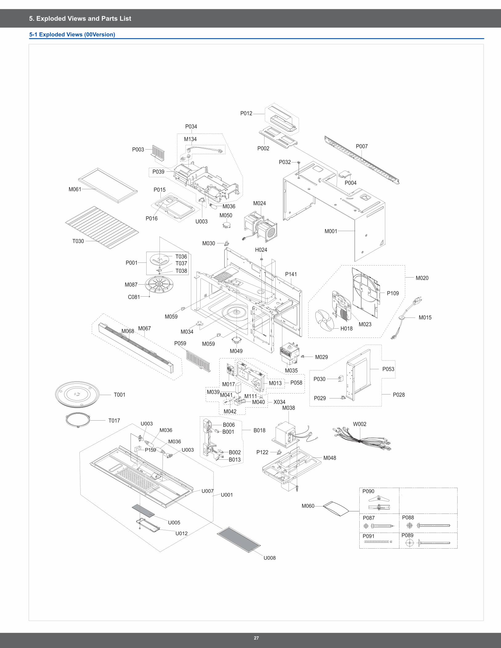
5. Exploded Views and Parts List
5-1 Exploded Views (00Version)
M015
M001
P109
M020
H018M023
P032
P004
M024
H024
P002
P012
P007
M050
P034
M134
M036
U003P016
P015M061
P003
P039
P029
P030
P053
T017
T001
W002
P122M048
M038M040
M111
M013 P058
X034
B006B001
M039M017
M042
M041
M049
M034
M059
M059
M087
C081
M068
P001T036T037T038
P059
M029
M035
P028
B018
M030
P141
B002B013
T030
M060
P090
P087 P088
P091 P089
M067
U012
U005
U008
U003
U003
U007
M036
M036
P159
U001
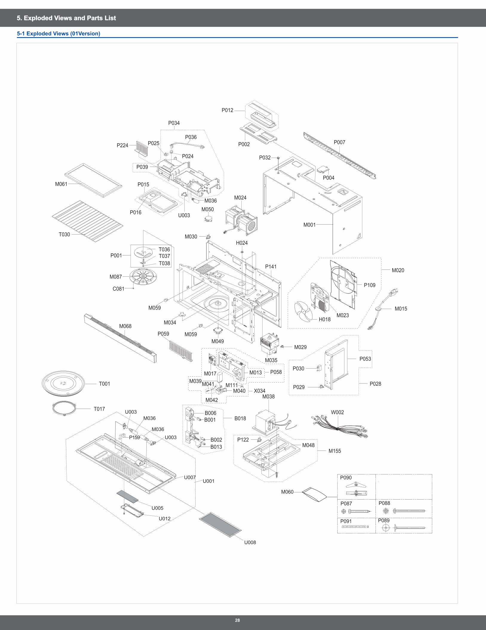
�8
5. Exploded Views and Parts List5. Exploded Views and Parts List
5-1 Exploded Views (01Version)
M015
M001
P109
M020
H018M023
P032
P004
M024
H024
P002
P012
P007
M050
P034
M036
U003P016
P015M061
P224
P039
P029
P030
P053
T017
T001
W002
P122M048
M038M040
M111
M013 P058
X034
B006B001
M039M017
M042
M041
M049
M034
M059
M059
M087
C081
M068
P001T036T037T038
P059
M029
M035
P028
M155
B018
M030
P141
B002B013
T030
M060
P090
P087 P088
P091 P089U012
U005
U008
U003
U003
U007
M036
M036
P159
U001
P025P036
P024
�9
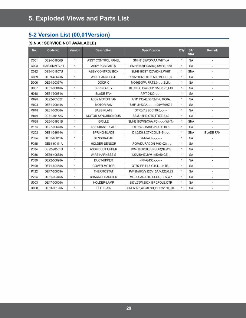
5. Exploded Views and Parts List
No. Code No. Version Description Specification Q’ty SA/SNA
Remark
C001 DE94-01806B 1 ASSY CONTROL PANEL SMH8165WG/XAA,WHT,-,A 1 SA -
C003 RAS-SM7GV-11 1 ASSY PCB PARTS SMH8165(FIGARO),SMPS, 120 1 SA -
C082 DE94-01807U 1 ASSY CONTROL BOX SMH8165ST,120V60HZ,WHIT 1 SNA -
C089 DE39-40673A 1 WIRE HARNESS-H 120V60HZ,OTR6 ALL MODEL,G 1 SA -
D006 DE64-00337A 1 DOOR-C MO1650WA,PP,T2 .0,-,-,-,BLK,- 1 SA -
D007 DE61-00048A 1 SPRING-KEY BLUING,HSWR,PI1 .95,D8 .75,L43 1 SA -
H018 DE31-90051A 1 BLADE-FAN P .P,T,D130,-,-,-,- 1 SA -
M020 DE92-90552F 1 ASSY MOTOR FAN JVM1730/40/50,SMF-U1630A, 1 SA -
M023 DE31-00044A 1 MOTOR FAN SMF-U1630A,-,-,-,-,120V/60HZ,2 1 SA -
M048 DE61-00906A 1 BASE-PLATE OTR6/7,SECC,T0 .6,-,-,-,- 1 SA -
M049 DE31-10172C 1 MOTOR SYNCHRONOUS SSM-16HR,OTR,FREE,3,60 1 SA -
M068 DE64-01951B 1 GRILLE SMH8165WG/XAA,PC,-,-,-,-,WHT,- 1 SNA -
M155 DE97-00678A 1 ASSY-BASE PLATE OTR6/7,-,BASE-PLATE T0 .6 1 SA -
M202 DE81-01614A 1 SPRING-BLADE D1,0/D9 .8,X7XCOILS=5,-,-,-, 1 SNA BLADE FAN
P024 DE32-60011A 1 SENSOR-GAS ST-MWO,-,-,-,-,-,- 1 SA -
P025 DE61-90111A 1 HOLDER-SENSOR -,POM(DURACON-M90-02),-,-, 1 SA -
P034 DE92-90551D 1 ASSY-DUCT UPPER JVM-1650/60,SENSOR(NEW S 1 SA -
P036 DE39-40678A 1 WIRE HARNESS-S 120V60HZ,JVM1450,60,GE,-, 1 SA -
P039 DE72-50098A 1 DUCT-UPPER -,PP-G430,-,-,-,-,- 1 SA -
P109 DE71-60455A 1 COVER-MOTOR OTR7,PP,T1 .5,G114,-,-,NTR,- 1 SA -
P122 DE47-20059A 1 THERMOSTAT PW-2N(8XV),125V15A,V,120/0,23 1 SA -
P224 DE61-00346A 1 BRACKET BARRIER MODULAR-OTR,SECC,T0 .5,W7 1 SA -
U003 DE47-00006A 1 HOLDER-LAMP 250V,75W,250X187 2POLE,OTR 1 SA -
U008 DE63-00196A 1 FILTER-AIR SMH7175,AL-MESH,T2 .0,W150,L34 1 SA -
5-� Version List (00,01Version)(S.N.A : SERVICE NOT AVAILABLE)
30
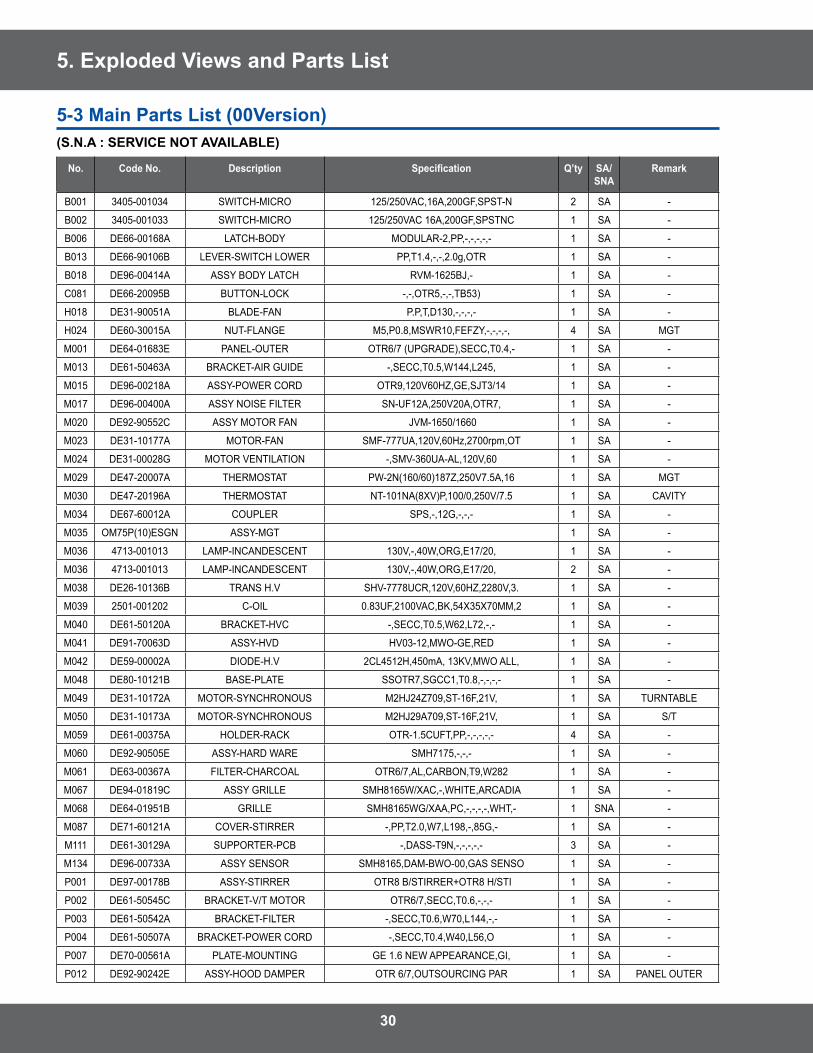
5. Exploded Views and Parts List
No. Code No. Description Specification Q’ty SA/SNA
Remark
B001 3405-001034 SWITCH-MICRO 125/250VAC,16A,200GF,SPST-N 2 SA -
B002 3405-001033 SWITCH-MICRO 125/250VAC 16A,200GF,SPSTNC 1 SA -
B006 DE66-00168A LATCH-BODY MODULAR-2,PP,-,-,-,-,- 1 SA -
B013 DE66-90106B LEVER-SWITCH LOWER PP,T1 .4,-,-,2 .0g,OTR 1 SA -
B018 DE96-00414A ASSY BODY LATCH RVM-1625BJ,- 1 SA -
C081 DE66-20095B BUTTON-LOCK -,-,OTR5,-,-,TB53) 1 SA -
H018 DE31-90051A BLADE-FAN P .P,T,D130,-,-,-,- 1 SA -
H024 DE60-30015A NUT-FLANGE M5,P0 .8,MSWR10,FEFZY,-,-,-,-, 4 SA MGT
M001 DE64-01683E PANEL-OUTER OTR6/7 (UPGRADE),SECC,T0 .4,- 1 SA -
M013 DE61-50463A BRACKET-AIR GUIDE -,SECC,T0 .5,W144,L245, 1 SA -
M015 DE96-00218A ASSY-POWER CORD OTR9,120V60HZ,GE,SJT3/14 1 SA -
M017 DE96-00400A ASSY NOISE FILTER SN-UF12A,250V20A,OTR7, 1 SA -
M020 DE92-90552C ASSY MOTOR FAN JVM-1650/1660 1 SA -
M023 DE31-10177A MOTOR-FAN SMF-777UA,120V,60Hz,2700rpm,OT 1 SA -
M024 DE31-00028G MOTOR VENTILATION -,SMV-360UA-AL,120V,60 1 SA -
M029 DE47-20007A THERMOSTAT PW-2N(160/60)187Z,250V7 .5A,16 1 SA MGT
M030 DE47-20196A THERMOSTAT NT-101NA(8XV)P,100/0,250V/7 .5 1 SA CAVITY
M034 DE67-60012A COUPLER SPS,-,12G,-,-,- 1 SA -
M035 OM75P(10)ESGN ASSY-MGT 1 SA -
M036 4713-001013 LAMP-INCANDESCENT 130V,-,40W,ORG,E17/20, 1 SA -
M036 4713-001013 LAMP-INCANDESCENT 130V,-,40W,ORG,E17/20, 2 SA -
M038 DE26-10136B TRANS H .V SHV-7778UCR,120V,60HZ,2280V,3 . 1 SA -
M039 2501-001202 C-OIL 0 .83UF,2100VAC,BK,54X35X70MM,2 1 SA -
M040 DE61-50120A BRACKET-HVC -,SECC,T0 .5,W62,L72,-,- 1 SA -
M041 DE91-70063D ASSY-HVD HV03-12,MWO-GE,RED 1 SA -
M042 DE59-00002A DIODE-H .V 2CL4512H,450mA, 13KV,MWO ALL, 1 SA -
M048 DE80-10121B BASE-PLATE SSOTR7,SGCC1,T0 .8,-,-,-,- 1 SA -
M049 DE31-10172A MOTOR-SYNCHRONOUS M2HJ24Z709,ST-16F,21V, 1 SA TURNTABLE
M050 DE31-10173A MOTOR-SYNCHRONOUS M2HJ29A709,ST-16F,21V, 1 SA S/T
M059 DE61-00375A HOLDER-RACK OTR-1 .5CUFT,PP,-,-,-,-,- 4 SA -
M060 DE92-90505E ASSY-HARD WARE SMH7175,-,-,- 1 SA -
M061 DE63-00367A FILTER-CHARCOAL OTR6/7,AL,CARBON,T9,W282 1 SA -
M067 DE94-01819C ASSY GRILLE SMH8165W/XAC,-,WHITE,ARCADIA 1 SA -
M068 DE64-01951B GRILLE SMH8165WG/XAA,PC,-,-,-,-,WHT,- 1 SNA -
M087 DE71-60121A COVER-STIRRER -,PP,T2 .0,W7,L198,-,85G,- 1 SA -
M111 DE61-30129A SUPPORTER-PCB -,DASS-T9N,-,-,-,-,- 3 SA -
M134 DE96-00733A ASSY SENSOR SMH8165,DAM-BWO-00,GAS SENSO 1 SA -
P001 DE97-00178B ASSY-STIRRER OTR8 B/STIRRER+OTR8 H/STI 1 SA -
P002 DE61-50545C BRACKET-V/T MOTOR OTR6/7,SECC,T0 .6,-,-,- 1 SA -
P003 DE61-50542A BRACKET-FILTER -,SECC,T0 .6,W70,L144,-,- 1 SA -
P004 DE61-50507A BRACKET-POWER CORD -,SECC,T0 .4,W40,L56,O 1 SA -
P007 DE70-00561A PLATE-MOUNTING GE 1 .6 NEW APPEARANCE,GI, 1 SA -
P012 DE92-90242E ASSY-HOOD DAMPER OTR 6/7,OUTSOURCING PAR 1 SA PANEL OUTER
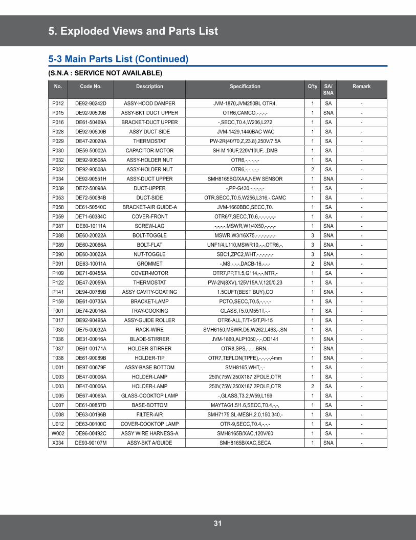
5-3 Main Parts List (00Version)(S.N.A : SERVICE NOT AVAILABLE)
31
5. Exploded Views and Parts List
No. Code No. Description Specification Q’ty SA/SNA
Remark
P012 DE92-90242D ASSY-HOOD DAMPER JVM-1870,JVM250BL OTR4, 1 SA -
P015 DE92-90509B ASSY-BKT DUCT UPPER OTR6,CAMCO,-,-,-,- 1 SNA -
P016 DE61-50469A BRACKET-DUCT UPPER -,SECC,T0 .4,W206,L272 1 SA -
P028 DE92-90500B ASSY DUCT SIDE JVM-1429,1440BAC WAC 1 SA -
P029 DE47-20020A THERMOSTAT PW-2R(40/70,Z,23 .8),250V/7 .5A 1 SA -
P030 DE59-50002A CAPACITOR-MOTOR SH-M 10UF,220V10UF,-,DMB 1 SA -
P032 DE92-90508A ASSY-HOLDER NUT OTR6,-,-,-,-,- 1 SA -
P032 DE92-90508A ASSY-HOLDER NUT OTR6,-,-,-,-,- 2 SA -
P034 DE92-90551H ASSY-DUCT UPPER SMH8165BG/XAA,NEW SENSOR 1 SNA -
P039 DE72-50098A DUCT-UPPER -,PP-G430,-,-,-,-,- 1 SA -
P053 DE72-50084B DUCT-SIDE OTR,SECC,T0 .5,W256,L316,-,CAMC 1 SA -
P058 DE61-50540C BRACKET-AIR GUIDE-A JVM-1660BBC,SECC,T0 . 1 SA -
P059 DE71-60384C COVER-FRONT OTR6/7,SECC,T0 .6,-,-,-,-,-,- 1 SA -
P087 DE60-10111A SCREW-LAG -,-,-,-,MSWR,W1/4X50,-,-,-,- 1 SNA -
P088 DE60-20022A BOLT-TOGGLE MSWR,W3/16X75,-,-,-,-,-,-,- 3 SNA -
P089 DE60-20066A BOLT-FLAT UNF1/4,L110,MSWR10,-,-,OTR6,-, 3 SNA -
P090 DE60-30022A NUT-TOGGLE SBC1,ZPC2,WHT,-,-,-,-,-,- 3 SNA -
P091 DE63-10011A GROMMET -,MS,-,-,-,DACB-16,-,-,- 2 SNA -
P109 DE71-60455A COVER-MOTOR OTR7,PP,T1 .5,G114,-,-,NTR,- 1 SA -
P122 DE47-20059A THERMOSTAT PW-2N(8XV),125V15A,V,120/0,23 1 SA -
P141 DE94-00789B ASSY CAVITY-COATING 1 .5CUFT(BEST BUY),CO 1 SNA -
P159 DE61-00735A BRACKET-LAMP PCTO,SECC,T0 .5,-,-,-,- 1 SA -
T001 DE74-20016A TRAY-COOKING GLASS,T5 .0,M551T,-,- 1 SA -
T017 DE92-90495A ASSY-GUIDE ROLLER OTR6-ALL,T/T+S/T,PI-15 1 SA -
T030 DE75-00032A RACK-WIRE SMH6150,MSWR,D5,W262,L463,-,SN 1 SA -
T036 DE31-00016A BLADE-STIRRER JVM-1860,ALP1050,-,-,OD141 1 SNA -
T037 DE61-00171A HOLDER-STIRRER OTR8,SPS,-,-,-,BRN,- 1 SNA -
T038 DE61-90089B HOLDER-TIP OTR7,TEFLON(TPFE),-,-,-,-,4mm 1 SNA -
U001 DE97-00679F ASSY-BASE BOTTOM SMH8165,WHT,-,- 1 SA -
U003 DE47-00006A HOLDER-LAMP 250V,75W,250X187 2POLE,OTR 1 SA -
U003 DE47-00006A HOLDER-LAMP 250V,75W,250X187 2POLE,OTR 2 SA -
U005 DE67-40063A GLASS-COOKTOP LAMP -,GLASS,T3 .2,W59,L159 1 SA -
U007 DE61-00857D BASE-BOTTOM MAYTAG1 .5/1 .6,SECC,T0 .4,-,-, 1 SA -
U008 DE63-00196B FILTER-AIR SMH7175,SL-MESH,2 .0,150,340,- 1 SA -
U012 DE63-00100C COVER-COOKTOP LAMP OTR-9,SECC,T0 .4,-,-,- 1 SA -
W002 DE96-00492C ASSY WIRE HARNESS-A SMH8165B/XAC,120V/60 1 SA -
X034 DE93-90107M ASSY-BKT A/GUIDE SMH8165B/XAC,SECA 1 SNA -
5-3 Main Parts List (Continued)(S.N.A : SERVICE NOT AVAILABLE)
3�
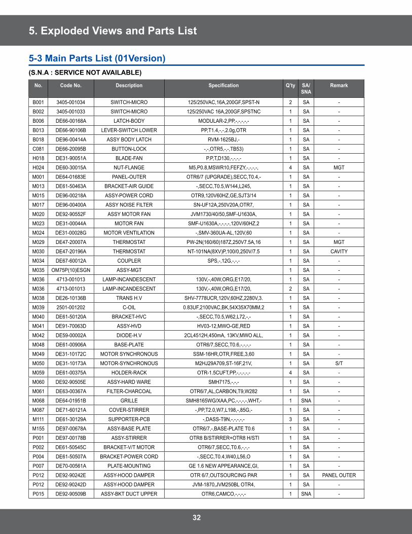
5. Exploded Views and Parts List
No. Code No. Description Specification Q’ty SA/SNA
Remark
B001 3405-001034 SWITCH-MICRO 125/250VAC,16A,200GF,SPST-N 2 SA -
B002 3405-001033 SWITCH-MICRO 125/250VAC 16A,200GF,SPSTNC 1 SA -
B006 DE66-00168A LATCH-BODY MODULAR-2,PP,-,-,-,-,- 1 SA -
B013 DE66-90106B LEVER-SWITCH LOWER PP,T1 .4,-,-,2 .0g,OTR 1 SA -
B018 DE96-00414A ASSY BODY LATCH RVM-1625BJ,- 1 SA -
C081 DE66-20095B BUTTON-LOCK -,-,OTR5,-,-,TB53) 1 SA -
H018 DE31-90051A BLADE-FAN P .P,T,D130,-,-,-,- 1 SA -
H024 DE60-30015A NUT-FLANGE M5,P0 .8,MSWR10,FEFZY,-,-,-,-, 4 SA MGT
M001 DE64-01683E PANEL-OUTER OTR6/7 (UPGRADE),SECC,T0 .4,- 1 SA -
M013 DE61-50463A BRACKET-AIR GUIDE -,SECC,T0 .5,W144,L245, 1 SA -
M015 DE96-00218A ASSY-POWER CORD OTR9,120V60HZ,GE,SJT3/14 1 SA -
M017 DE96-00400A ASSY NOISE FILTER SN-UF12A,250V20A,OTR7, 1 SA -
M020 DE92-90552F ASSY MOTOR FAN JVM1730/40/50,SMF-U1630A, 1 SA -
M023 DE31-00044A MOTOR FAN SMF-U1630A,-,-,-,-,120V/60HZ,2 1 SA -
M024 DE31-00028G MOTOR VENTILATION -,SMV-360UA-AL,120V,60 1 SA -
M029 DE47-20007A THERMOSTAT PW-2N(160/60)187Z,250V7 .5A,16 1 SA MGT
M030 DE47-20196A THERMOSTAT NT-101NA(8XV)P,100/0,250V/7 .5 1 SA CAVITY
M034 DE67-60012A COUPLER SPS,-,12G,-,-,- 1 SA -
M035 OM75P(10)ESGN ASSY-MGT 1 SA -
M036 4713-001013 LAMP-INCANDESCENT 130V,-,40W,ORG,E17/20, 1 SA -
M036 4713-001013 LAMP-INCANDESCENT 130V,-,40W,ORG,E17/20, 2 SA -
M038 DE26-10136B TRANS H .V SHV-7778UCR,120V,60HZ,2280V,3 . 1 SA -
M039 2501-001202 C-OIL 0 .83UF,2100VAC,BK,54X35X70MM,2 1 SA -
M040 DE61-50120A BRACKET-HVC -,SECC,T0 .5,W62,L72,-,- 1 SA -
M041 DE91-70063D ASSY-HVD HV03-12,MWO-GE,RED 1 SA -
M042 DE59-00002A DIODE-H .V 2CL4512H,450mA, 13KV,MWO ALL, 1 SA -
M048 DE61-00906A BASE-PLATE OTR6/7,SECC,T0 .6,-,-,-,- 1 SA -
M049 DE31-10172C MOTOR SYNCHRONOUS SSM-16HR,OTR,FREE,3,60 1 SA -
M050 DE31-10173A MOTOR-SYNCHRONOUS M2HJ29A709,ST-16F,21V, 1 SA S/T
M059 DE61-00375A HOLDER-RACK OTR-1 .5CUFT,PP,-,-,-,-,- 4 SA -
M060 DE92-90505E ASSY-HARD WARE SMH7175,-,-,- 1 SA -
M061 DE63-00367A FILTER-CHARCOAL OTR6/7,AL,CARBON,T9,W282 1 SA -
M068 DE64-01951B GRILLE SMH8165WG/XAA,PC,-,-,-,-,WHT,- 1 SNA -
M087 DE71-60121A COVER-STIRRER -,PP,T2 .0,W7,L198,-,85G,- 1 SA -
M111 DE61-30129A SUPPORTER-PCB -,DASS-T9N,-,-,-,-,- 3 SA -
M155 DE97-00678A ASSY-BASE PLATE OTR6/7,-,BASE-PLATE T0 .6 1 SA -
P001 DE97-00178B ASSY-STIRRER OTR8 B/STIRRER+OTR8 H/STI 1 SA -
P002 DE61-50545C BRACKET-V/T MOTOR OTR6/7,SECC,T0 .6,-,-,- 1 SA -
P004 DE61-50507A BRACKET-POWER CORD -,SECC,T0 .4,W40,L56,O 1 SA -
P007 DE70-00561A PLATE-MOUNTING GE 1 .6 NEW APPEARANCE,GI, 1 SA -
P012 DE92-90242E ASSY-HOOD DAMPER OTR 6/7,OUTSOURCING PAR 1 SA PANEL OUTER
P012 DE92-90242D ASSY-HOOD DAMPER JVM-1870,JVM250BL OTR4, 1 SA -
P015 DE92-90509B ASSY-BKT DUCT UPPER OTR6,CAMCO,-,-,-,- 1 SNA -
5-3 Main Parts List (01Version)(S.N.A : SERVICE NOT AVAILABLE)
33
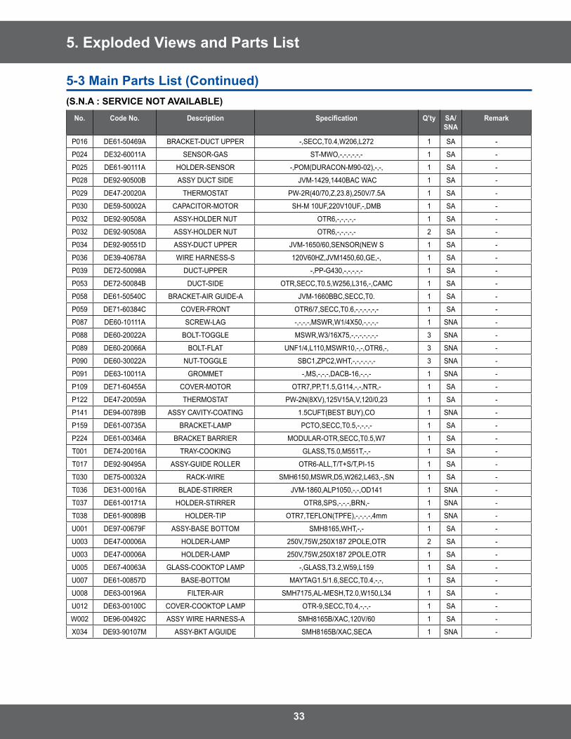
5. Exploded Views and Parts List
No. Code No. Description Specification Q’ty SA/SNA
Remark
P016 DE61-50469A BRACKET-DUCT UPPER -,SECC,T0 .4,W206,L272 1 SA -
P024 DE32-60011A SENSOR-GAS ST-MWO,-,-,-,-,-,- 1 SA -
P025 DE61-90111A HOLDER-SENSOR -,POM(DURACON-M90-02),-,-, 1 SA -
P028 DE92-90500B ASSY DUCT SIDE JVM-1429,1440BAC WAC 1 SA -
P029 DE47-20020A THERMOSTAT PW-2R(40/70,Z,23 .8),250V/7 .5A 1 SA -
P030 DE59-50002A CAPACITOR-MOTOR SH-M 10UF,220V10UF,-,DMB 1 SA -
P032 DE92-90508A ASSY-HOLDER NUT OTR6,-,-,-,-,- 1 SA -
P032 DE92-90508A ASSY-HOLDER NUT OTR6,-,-,-,-,- 2 SA -
P034 DE92-90551D ASSY-DUCT UPPER JVM-1650/60,SENSOR(NEW S 1 SA -
P036 DE39-40678A WIRE HARNESS-S 120V60HZ,JVM1450,60,GE,-, 1 SA -
P039 DE72-50098A DUCT-UPPER -,PP-G430,-,-,-,-,- 1 SA -
P053 DE72-50084B DUCT-SIDE OTR,SECC,T0 .5,W256,L316,-,CAMC 1 SA -
P058 DE61-50540C BRACKET-AIR GUIDE-A JVM-1660BBC,SECC,T0 . 1 SA -
P059 DE71-60384C COVER-FRONT OTR6/7,SECC,T0 .6,-,-,-,-,-,- 1 SA -
P087 DE60-10111A SCREW-LAG -,-,-,-,MSWR,W1/4X50,-,-,-,- 1 SNA -
P088 DE60-20022A BOLT-TOGGLE MSWR,W3/16X75,-,-,-,-,-,-,- 3 SNA -
P089 DE60-20066A BOLT-FLAT UNF1/4,L110,MSWR10,-,-,OTR6,-, 3 SNA -
P090 DE60-30022A NUT-TOGGLE SBC1,ZPC2,WHT,-,-,-,-,-,- 3 SNA -
P091 DE63-10011A GROMMET -,MS,-,-,-,DACB-16,-,-,- 1 SNA -
P109 DE71-60455A COVER-MOTOR OTR7,PP,T1 .5,G114,-,-,NTR,- 1 SA -
P122 DE47-20059A THERMOSTAT PW-2N(8XV),125V15A,V,120/0,23 1 SA -
P141 DE94-00789B ASSY CAVITY-COATING 1 .5CUFT(BEST BUY),CO 1 SNA -
P159 DE61-00735A BRACKET-LAMP PCTO,SECC,T0 .5,-,-,-,- 1 SA -
P224 DE61-00346A BRACKET BARRIER MODULAR-OTR,SECC,T0 .5,W7 1 SA -
T001 DE74-20016A TRAY-COOKING GLASS,T5 .0,M551T,-,- 1 SA -
T017 DE92-90495A ASSY-GUIDE ROLLER OTR6-ALL,T/T+S/T,PI-15 1 SA -
T030 DE75-00032A RACK-WIRE SMH6150,MSWR,D5,W262,L463,-,SN 1 SA -
T036 DE31-00016A BLADE-STIRRER JVM-1860,ALP1050,-,-,OD141 1 SNA -
T037 DE61-00171A HOLDER-STIRRER OTR8,SPS,-,-,-,BRN,- 1 SNA -
T038 DE61-90089B HOLDER-TIP OTR7,TEFLON(TPFE),-,-,-,-,4mm 1 SNA -
U001 DE97-00679F ASSY-BASE BOTTOM SMH8165,WHT,-,- 1 SA -
U003 DE47-00006A HOLDER-LAMP 250V,75W,250X187 2POLE,OTR 2 SA -
U003 DE47-00006A HOLDER-LAMP 250V,75W,250X187 2POLE,OTR 1 SA -
U005 DE67-40063A GLASS-COOKTOP LAMP -,GLASS,T3 .2,W59,L159 1 SA -
U007 DE61-00857D BASE-BOTTOM MAYTAG1 .5/1 .6,SECC,T0 .4,-,-, 1 SA -
U008 DE63-00196A FILTER-AIR SMH7175,AL-MESH,T2 .0,W150,L34 1 SA -
U012 DE63-00100C COVER-COOKTOP LAMP OTR-9,SECC,T0 .4,-,-,- 1 SA -
W002 DE96-00492C ASSY WIRE HARNESS-A SMH8165B/XAC,120V/60 1 SA -
X034 DE93-90107M ASSY-BKT A/GUIDE SMH8165B/XAC,SECA 1 SNA -
(S.N.A : SERVICE NOT AVAILABLE)
5-3 Main Parts List (Continued)
34
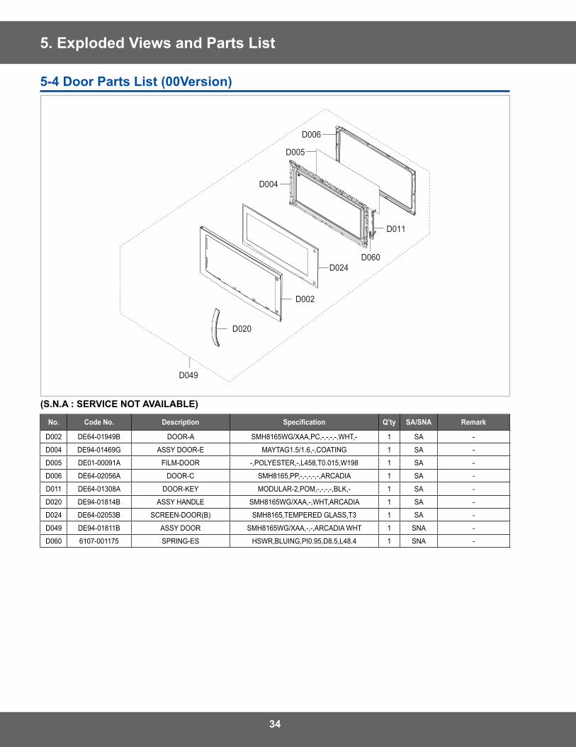
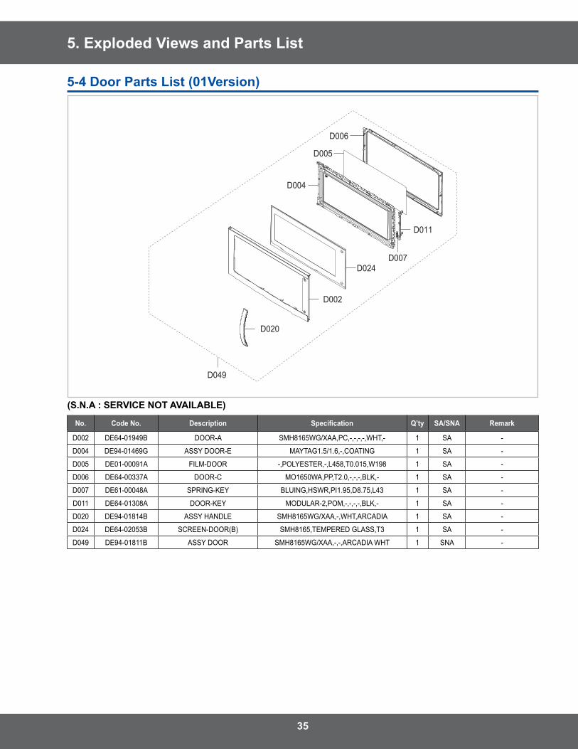
5. Exploded Views and Parts List
(S.N.A : SERVICE NOT AVAILABLE)
No. Code No. Description Specification Q’ty SA/SNA Remark
D002 DE64-01949B DOOR-A SMH8165WG/XAA,PC,-,-,-,-,WHT,- 1 SA -
D004 DE94-01469G ASSY DOOR-E MAYTAG1 .5/1 .6,-,COATING 1 SA -
D005 DE01-00091A FILM-DOOR -,POLYESTER,-,L458,T0 .015,W198 1 SA -
D006 DE64-02056A DOOR-C SMH8165,PP,-,-,-,-,-,ARCADIA 1 SA -
D011 DE64-01308A DOOR-KEY MODULAR-2,POM,-,-,-,-,BLK,- 1 SA -
D020 DE94-01814B ASSY HANDLE SMH8165WG/XAA,-,WHT,ARCADIA 1 SA -
D024 DE64-02053B SCREEN-DOOR(B) SMH8165,TEMPERED GLASS,T3 1 SA -
D049 DE94-01811B ASSY DOOR SMH8165WG/XAA,-,-,ARCADIA WHT 1 SNA -
D060 6107-001175 SPRING-ES HSWR,BLUING,PI0 .95,D8 .5,L48 .4 1 SNA -
D020
D002
D024
D004
D049
D011
D005
D060
D006
5-4 Door Parts List (00Version)
35
5. Exploded Views and Parts List
(S.N.A : SERVICE NOT AVAILABLE)
No. Code No. Description Specification Q’ty SA/SNA Remark
D002 DE64-01949B DOOR-A SMH8165WG/XAA,PC,-,-,-,-,WHT,- 1 SA -
D004 DE94-01469G ASSY DOOR-E MAYTAG1 .5/1 .6,-,COATING 1 SA -
D005 DE01-00091A FILM-DOOR -,POLYESTER,-,L458,T0 .015,W198 1 SA -
D006 DE64-00337A DOOR-C MO1650WA,PP,T2 .0,-,-,-,BLK,- 1 SA -
D007 DE61-00048A SPRING-KEY BLUING,HSWR,PI1 .95,D8 .75,L43 1 SA -
D011 DE64-01308A DOOR-KEY MODULAR-2,POM,-,-,-,-,BLK,- 1 SA -
D020 DE94-01814B ASSY HANDLE SMH8165WG/XAA,-,WHT,ARCADIA 1 SA -
D024 DE64-02053B SCREEN-DOOR(B) SMH8165,TEMPERED GLASS,T3 1 SA -
D049 DE94-01811B ASSY DOOR SMH8165WG/XAA,-,-,ARCADIA WHT 1 SNA -
D020
D002
D024
D004
D049
D011
D005
D007
D006
5-4 Door Parts List (01Version)
36
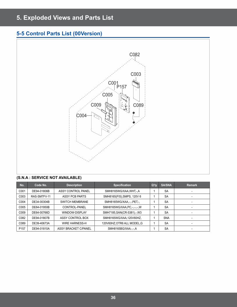
5. Exploded Views and Parts List
(S.N.A : SERVICE NOT AVAILABLE)
No. Code No. Description Specification Q’ty SA/SNA Remark
C001 DE94-01806B ASSY CONTROL PANEL SMH8165WG/XAA,WHT,-,A 1 SA -
C003 RAS-SM7FV-11 ASSY PCB PARTS SMH8165(FIS),SMPS, 120V 6 1 SA -
C004 DE34-00304B SWITCH MEMBRANE SMH8165WG/XAA,-,-,PET,-, 1 SA -
C005 DE64-01950B CONTROL-PANEL SMH8165WG/XAA,PC,-,-,-,-,W 1 SA -
C009 DE64-00766D WINDOW-DISPLAY SMH7185,SAN(CR-5381),-,W3 1 SA -
C082 DE94-01807B ASSY CONTROL BOX SMH8165WG/XAA,120V60HZ, 1 SNA -
C089 DE39-40673A WIRE HARNESS-H 120V60HZ,OTR6 ALL MODEL,G 1 SA -
P157 DE94-01810A ASSY BRACKET C/PANEL SMH8165BG/XAA,-,-,A 1 SA -
C003
C089
C082
C004
C009
C005
C001P157
5-5 Control Parts List (00Version)
37
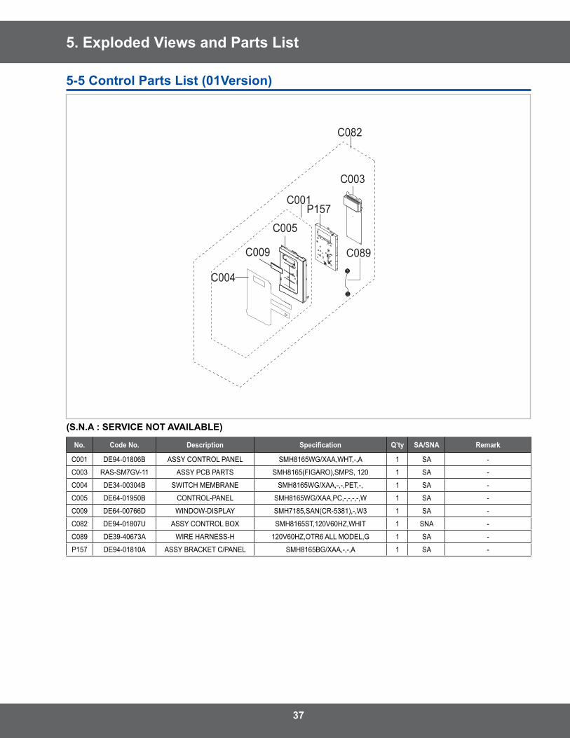
5. Exploded Views and Parts List
(S.N.A : SERVICE NOT AVAILABLE)
No. Code No. Description Specification Q’ty SA/SNA Remark
C001 DE94-01806B ASSY CONTROL PANEL SMH8165WG/XAA,WHT,-,A 1 SA -
C003 RAS-SM7GV-11 ASSY PCB PARTS SMH8165(FIGARO),SMPS, 120 1 SA -
C004 DE34-00304B SWITCH MEMBRANE SMH8165WG/XAA,-,-,PET,-, 1 SA -
C005 DE64-01950B CONTROL-PANEL SMH8165WG/XAA,PC,-,-,-,-,W 1 SA -
C009 DE64-00766D WINDOW-DISPLAY SMH7185,SAN(CR-5381),-,W3 1 SA -
C082 DE94-01807U ASSY CONTROL BOX SMH8165ST,120V60HZ,WHIT 1 SNA -
C089 DE39-40673A WIRE HARNESS-H 120V60HZ,OTR6 ALL MODEL,G 1 SA -
P157 DE94-01810A ASSY BRACKET C/PANEL SMH8165BG/XAA,-,-,A 1 SA -
C003
C089
C082
C004
C009
C005
C001P157
5-5 Control Parts List (01Version)
38
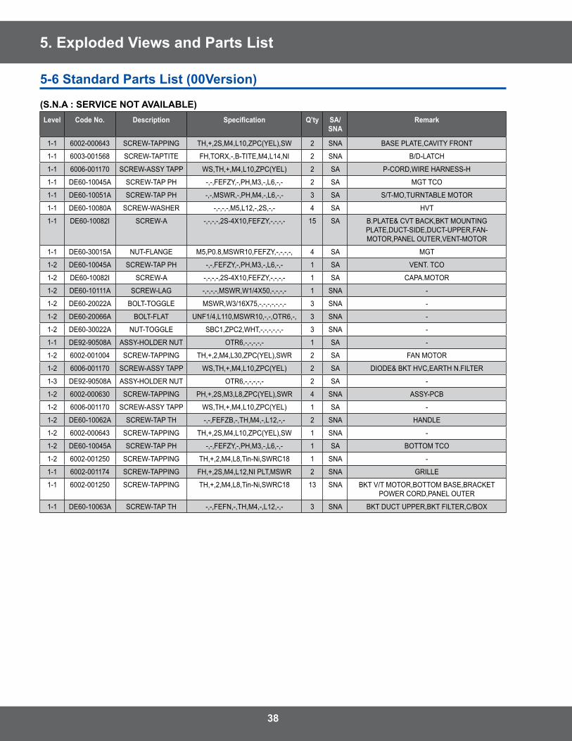
5. Exploded Views and Parts List
5-6 Standard Parts List (00Version)
(S.N.A : SERVICE NOT AVAILABLE)Level Code No. Description Specification Q’ty SA/
SNARemark
1-1 6002-000643 SCREW-TAPPING TH,+,2S,M4,L10,ZPC(YEL),SW 2 SNA BASE PLATE,CAVITY FRONT
1-1 6003-001568 SCREW-TAPTITE FH,TORX,-,B-TITE,M4,L14,NI 2 SNA B/D-LATCH
1-1 6006-001170 SCREW-ASSY TAPP WS,TH,+,M4,L10,ZPC(YEL) 2 SA P-CORD,WIRE HARNESS-H
1-1 DE60-10045A SCREW-TAP PH -,-,FEFZY,-,PH,M3,-,L6,-,- 2 SA MGT TCO
1-1 DE60-10051A SCREW-TAP PH -,-,MSWR,-,PH,M4,-,L6,-,- 3 SA S/T-MO,TURNTABLE MOTOR
1-1 DE60-10080A SCREW-WASHER -,-,-,-,M5,L12,-,2S,-,- 4 SA HVT
1-1 DE60-10082I SCREW-A -,-,-,-,2S-4X10,FEFZY,-,-,-,- 15 SA B .PLATE& CVT BACK,BKT MOUNTING PLATE,DUCT-SIDE,DUCT-UPPER,FAN-MOTOR,PANEL OUTER,VENT-MOTOR
1-1 DE60-30015A NUT-FLANGE M5,P0 .8,MSWR10,FEFZY,-,-,-,-, 4 SA MGT
1-2 DE60-10045A SCREW-TAP PH -,-,FEFZY,-,PH,M3,-,L6,-,- 1 SA VENT . TCO
1-2 DE60-10082I SCREW-A -,-,-,-,2S-4X10,FEFZY,-,-,-,- 1 SA CAPA .MOTOR
1-2 DE60-10111A SCREW-LAG -,-,-,-,MSWR,W1/4X50,-,-,-,- 1 SNA -
1-2 DE60-20022A BOLT-TOGGLE MSWR,W3/16X75,-,-,-,-,-,-,- 3 SNA -
1-2 DE60-20066A BOLT-FLAT UNF1/4,L110,MSWR10,-,-,OTR6,-, 3 SNA -
1-2 DE60-30022A NUT-TOGGLE SBC1,ZPC2,WHT,-,-,-,-,-,- 3 SNA -
1-1 DE92-90508A ASSY-HOLDER NUT OTR6,-,-,-,-,- 1 SA -
1-2 6002-001004 SCREW-TAPPING TH,+,2,M4,L30,ZPC(YEL),SWR 2 SA FAN MOTOR
1-2 6006-001170 SCREW-ASSY TAPP WS,TH,+,M4,L10,ZPC(YEL) 2 SA DIODE& BKT HVC,EARTH N .FILTER
1-3 DE92-90508A ASSY-HOLDER NUT OTR6,-,-,-,-,- 2 SA -
1-2 6002-000630 SCREW-TAPPING PH,+,2S,M3,L8,ZPC(YEL),SWR 4 SNA ASSY-PCB
1-2 6006-001170 SCREW-ASSY TAPP WS,TH,+,M4,L10,ZPC(YEL) 1 SA -
1-2 DE60-10062A SCREW-TAP TH -,-,FEFZB,-,TH,M4,-,L12,-,- 2 SNA HANDLE
1-2 6002-000643 SCREW-TAPPING TH,+,2S,M4,L10,ZPC(YEL),SW 1 SNA -
1-2 DE60-10045A SCREW-TAP PH -,-,FEFZY,-,PH,M3,-,L6,-,- 1 SA BOTTOM TCO
1-2 6002-001250 SCREW-TAPPING TH,+,2,M4,L8,Tin-Ni,SWRC18 1 SNA -
1-1 6002-001174 SCREW-TAPPING FH,+,2S,M4,L12,NI PLT,MSWR 2 SNA GRILLE
1-1 6002-001250 SCREW-TAPPING TH,+,2,M4,L8,Tin-Ni,SWRC18 13 SNA BKT V/T MOTOR,BOTTOM BASE,BRACKET POWER CORD,PANEL OUTER
1-1 DE60-10063A SCREW-TAP TH -,-,FEFN,-,TH,M4,-,L12,-,- 3 SNA BKT DUCT UPPER,BKT FILTER,C/BOX
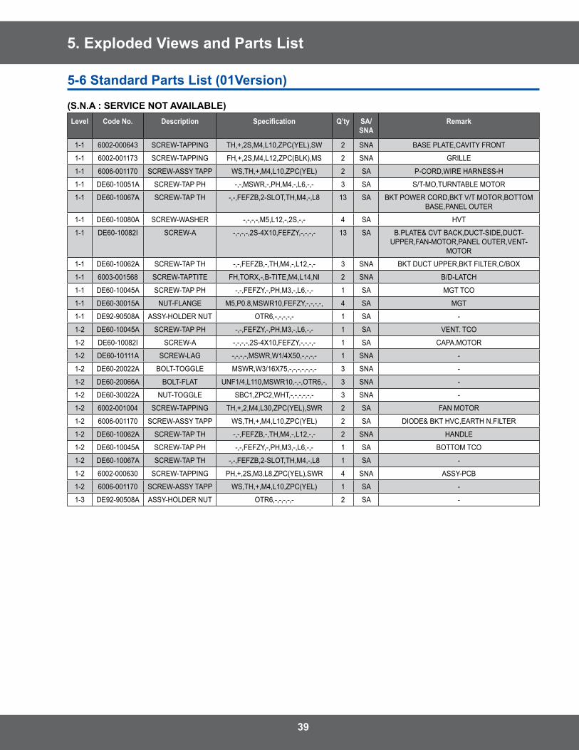
39
5. Exploded Views and Parts List
5-6 Standard Parts List (01Version)
(S.N.A : SERVICE NOT AVAILABLE)Level Code No. Description Specification Q’ty SA/
SNARemark
1-1 6002-000643 SCREW-TAPPING TH,+,2S,M4,L10,ZPC(YEL),SW 2 SNA BASE PLATE,CAVITY FRONT
1-1 6002-001173 SCREW-TAPPING FH,+,2S,M4,L12,ZPC(BLK),MS 2 SNA GRILLE
1-1 6006-001170 SCREW-ASSY TAPP WS,TH,+,M4,L10,ZPC(YEL) 2 SA P-CORD,WIRE HARNESS-H
1-1 DE60-10051A SCREW-TAP PH -,-,MSWR,-,PH,M4,-,L6,-,- 3 SA S/T-MO,TURNTABLE MOTOR
1-1 DE60-10067A SCREW-TAP TH -,-,FEFZB,2-SLOT,TH,M4,-,L8 13 SA BKT POWER CORD,BKT V/T MOTOR,BOTTOM BASE,PANEL OUTER
1-1 DE60-10080A SCREW-WASHER -,-,-,-,M5,L12,-,2S,-,- 4 SA HVT
1-1 DE60-10082I SCREW-A -,-,-,-,2S-4X10,FEFZY,-,-,-,- 13 SA B .PLATE& CVT BACK,DUCT-SIDE,DUCT-UPPER,FAN-MOTOR,PANEL OUTER,VENT-
MOTOR
1-1 DE60-10062A SCREW-TAP TH -,-,FEFZB,-,TH,M4,-,L12,-,- 3 SNA BKT DUCT UPPER,BKT FILTER,C/BOX
1-1 6003-001568 SCREW-TAPTITE FH,TORX,-,B-TITE,M4,L14,NI 2 SNA B/D-LATCH
1-1 DE60-10045A SCREW-TAP PH -,-,FEFZY,-,PH,M3,-,L6,-,- 1 SA MGT TCO
1-1 DE60-30015A NUT-FLANGE M5,P0 .8,MSWR10,FEFZY,-,-,-,-, 4 SA MGT
1-1 DE92-90508A ASSY-HOLDER NUT OTR6,-,-,-,-,- 1 SA -
1-2 DE60-10045A SCREW-TAP PH -,-,FEFZY,-,PH,M3,-,L6,-,- 1 SA VENT . TCO
1-2 DE60-10082I SCREW-A -,-,-,-,2S-4X10,FEFZY,-,-,-,- 1 SA CAPA .MOTOR
1-2 DE60-10111A SCREW-LAG -,-,-,-,MSWR,W1/4X50,-,-,-,- 1 SNA -
1-2 DE60-20022A BOLT-TOGGLE MSWR,W3/16X75,-,-,-,-,-,-,- 3 SNA -
1-2 DE60-20066A BOLT-FLAT UNF1/4,L110,MSWR10,-,-,OTR6,-, 3 SNA -
1-2 DE60-30022A NUT-TOGGLE SBC1,ZPC2,WHT,-,-,-,-,-,- 3 SNA -
1-2 6002-001004 SCREW-TAPPING TH,+,2,M4,L30,ZPC(YEL),SWR 2 SA FAN MOTOR
1-2 6006-001170 SCREW-ASSY TAPP WS,TH,+,M4,L10,ZPC(YEL) 2 SA DIODE& BKT HVC,EARTH N .FILTER
1-2 DE60-10062A SCREW-TAP TH -,-,FEFZB,-,TH,M4,-,L12,-,- 2 SNA HANDLE
1-2 DE60-10045A SCREW-TAP PH -,-,FEFZY,-,PH,M3,-,L6,-,- 1 SA BOTTOM TCO
1-2 DE60-10067A SCREW-TAP TH -,-,FEFZB,2-SLOT,TH,M4,-,L8 1 SA -
1-2 6002-000630 SCREW-TAPPING PH,+,2S,M3,L8,ZPC(YEL),SWR 4 SNA ASSY-PCB
1-2 6006-001170 SCREW-ASSY TAPP WS,TH,+,M4,L10,ZPC(YEL) 1 SA -
1-3 DE92-90508A ASSY-HOLDER NUT OTR6,-,-,-,-,- 2 SA -
40
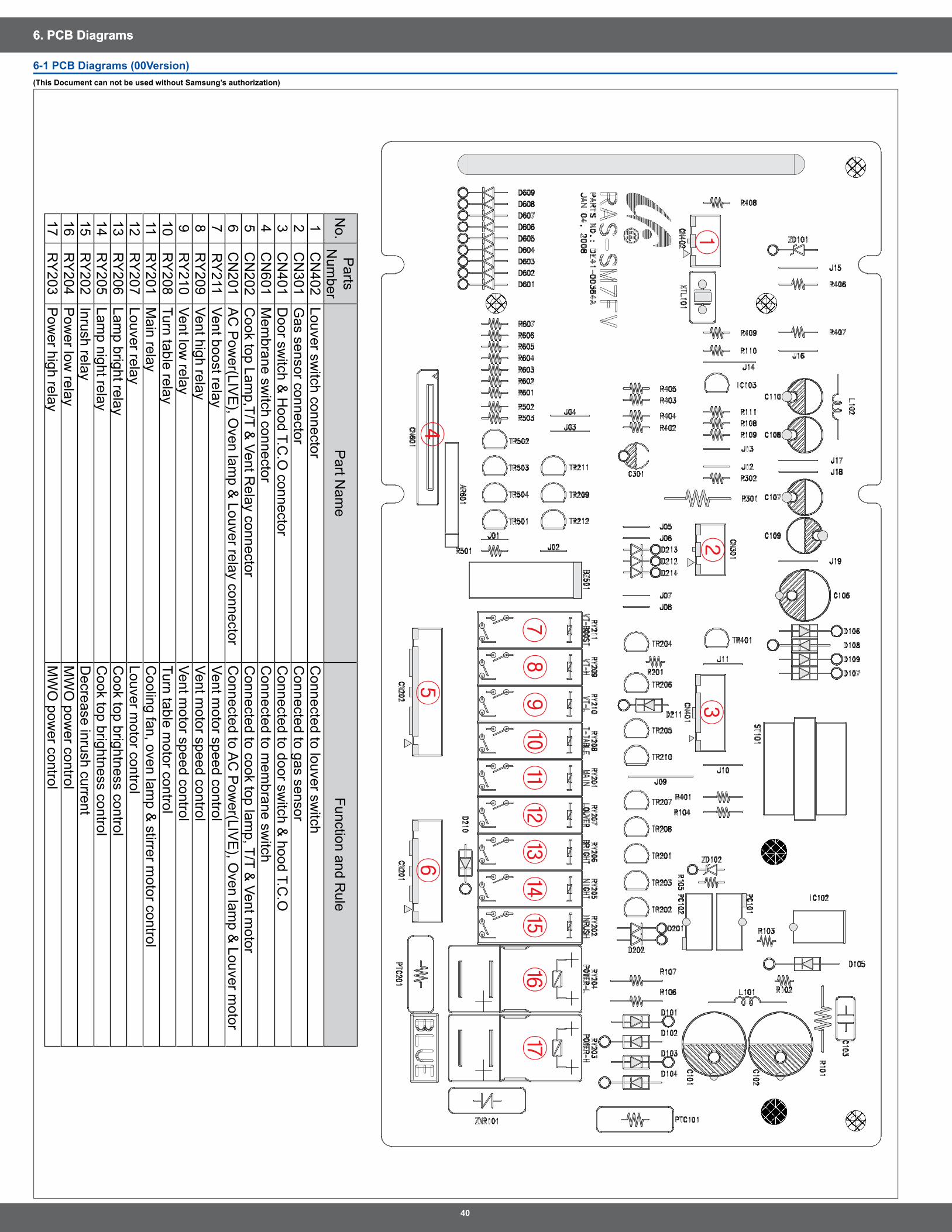
6. PCB Diagrams6. PCB Diagrams
6-1 PCB Diagrams (00Version)(This Document can not be used without Samsung’s authorization)
⑪⑫⑬⑭⑮
①②
③
④⑥
⑤
⑧⑨⑩
⑦
No .
Parts
Num
berP
art Nam
eFunction and R
ule
1C
N402
Louver switch connector
Connected to louver sw
itch2
CN
301G
as sensor connectorC
onnected to gas sensor3
CN
401D
oor switch &
Hood T .C
.O connector
Connected to door sw
itch & hood T .C
.O4
CN
601M
embrane sw
itch connectorC
onnected to mem
brane switch
5C
N202
Cook top Lam
p,T/T & Vent R
elay connectorC
onnected to cook top lamp, T/T &
Vent motor
6C
N201
AC
Pow
er(LIVE
), Oven lam
p & Louver relay connector
Connected to A
C P
ower(LIV
E), O
ven lamp &
Louver motor
7R
Y211
Vent boost relayVent m
otor speed control8
RY
209Vent high relay
Vent motor speed control
9R
Y210
Vent low relay
Vent motor speed control
10R
Y208
Turn table relayTurn table m
otor control11
RY
201M
ain relayC
ooling fan, oven lamp &
stirrer motor control
12R
Y207
Louver relayLouver m
otor control13
RY
206Lam
p bright relayC
ook top brightness control14
RY
205Lam
p night relayC
ook top brightness control15
RY
202Inrush relay
Decrease inrush current
16R
Y204
Pow
er low relay
MW
O pow
er control17
RY
203P
ower high relay
MW
O pow
er control
41
6. PCB Diagrams
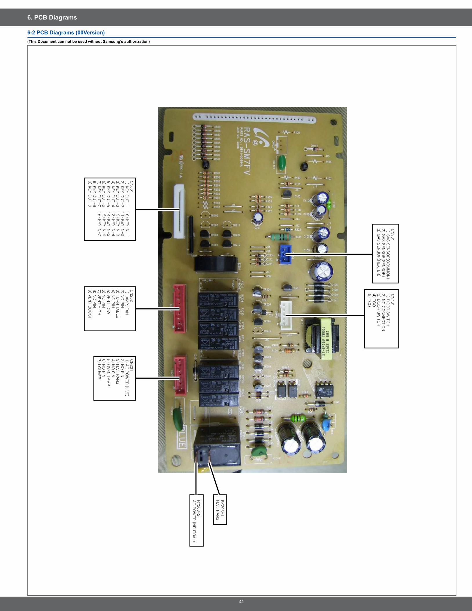
6-� PCB Diagrams (00Version)(This Document can not be used without Samsung’s authorization)
CN
301
1) G
AS S
EN
SO
R(C
OM
MO
N)
2) G
AS S
EN
SO
R(S
EN
SO
R)
3) G
AS S
EN
SO
R(H
EATER)
CN
601
1) K
EY O
UT-1
2) K
EY O
UT-2
3) K
EY O
UT-3
4) K
EY O
UT-4
5) K
EY O
UT-5
6) K
EY O
UT-6
7) K
EY O
UT-7
8) K
EY O
UT-8
9) K
EY O
UT-9
CN
401
1) D
OO
R S
WIT
CH
2) N
O C
ON
NEC
TIO
N3) D
OO
R S
WIT
CH
4) T
CO
5) T
CO
RY203-1
H.V
.TRAN
S
RY203-2
AC
PO
WER
(NEU
TR
AL)
10) K
EY IN
-1
11) K
EY IN
-2
12) K
EY IN
-3
13) K
EY IN
-4
14) K
EY IN
-5
15) K
EY IN
-6
16) K
EY IN
-7
CN
202
1) L
AM
P, F
AN
2) N
O P
IN3) T
URN
TAB
LE
4) N
O P
IN5) V
EN
T L
OW
6) N
O P
IN7) V
EN
T H
IGH
8) N
O P
IN9) V
EN
T B
OO
ST
CN
201
1) A
C P
OW
ER (L
IVE)
2) N
O P
IN3) H
.V.T
RAN
S4) N
O P
IN5) O
VEN
LAM
P6) N
O P
IN7) L
OU
VER
4�
6. PCB Diagrams6. PCB Diagrams
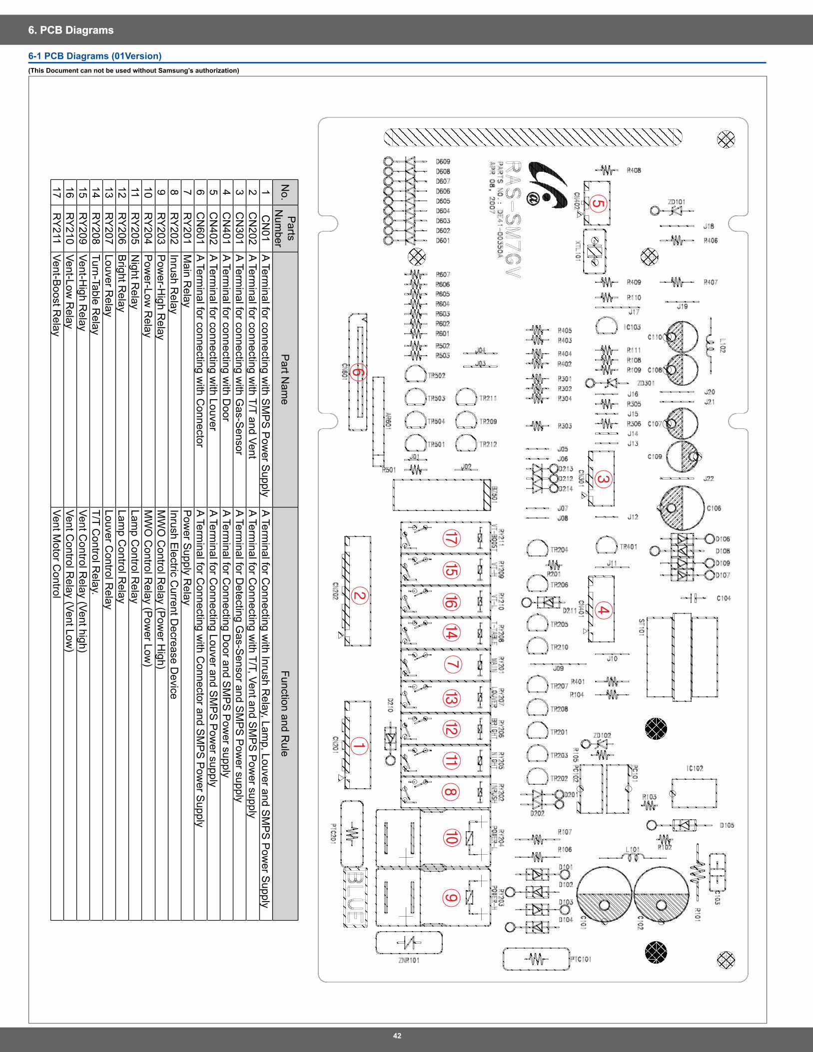
6-1 PCB Diagrams (01Version)(This Document can not be used without Samsung’s authorization)
①②
③④
⑥
⑤
⑧⑨
⑩⑪
⑫⑬
⑭⑮
⑦
No .
Parts
Num
berP
art Nam
eFunction and R
ule
1C
N01
A Terminal for connecting w
ith SM
PS
Pow
er Supply
A Terminal for C
onnecting with Inrush R
elay, Lamp, Louver and S
MP
S P
ower S
upply2
CN
202A Term
inal for connecting with T/T and Vent
A Terminal for C
onnecting with T/T, Vent and S
MP
S P
ower supply
3C
N301
A Terminal for connecting w
ith Gas-S
ensorA Term
inal for Detecting G
as-Sensor and S
MP
S P
ower supply
4C
N401
A Terminal for connecting w
ith Door
A Terminal for C
onnecting Door and S
MP
S P
ower supply
5C
N402
A Terminal for connecting w
ith LouverA Term
inal for Connecting Louver and S
MP
S P
ower supply
6C
N601
A Terminal for connecting w
ith Connector
A Terminal for C
onnecting with C
onnector and SM
PS
Pow
er Supply
7R
Y201
Main R
elayP
ower S
upply Relay
8R
Y202
Inrush Relay
Inrush Electric C
urrent Decrease D
evice9
RY
203P
ower-H
igh Relay
MW
O C
ontrol Relay (P
ower H
igh)10
RY
204P
ower-Low
Relay
MW
O C
ontrol Relay (P
ower Low
)11
RY
205N
ight Relay
Lamp C
ontrol Relay
12R
Y206
Bright R
elayLam
p Control R
elay13
RY
207Louver R
elayLouver C
ontrol Relay
14R
Y208
Turn-Table Relay
T/T Control R
elay .15
RY
209Vent-H
igh Relay
Vent Control R
elay (Vent high)16
RY
210Vent-Low
Relay
Vent Control R
elay (Vent Low)
17R
Y211
Vent-Boost R
elayVent M
otor Control
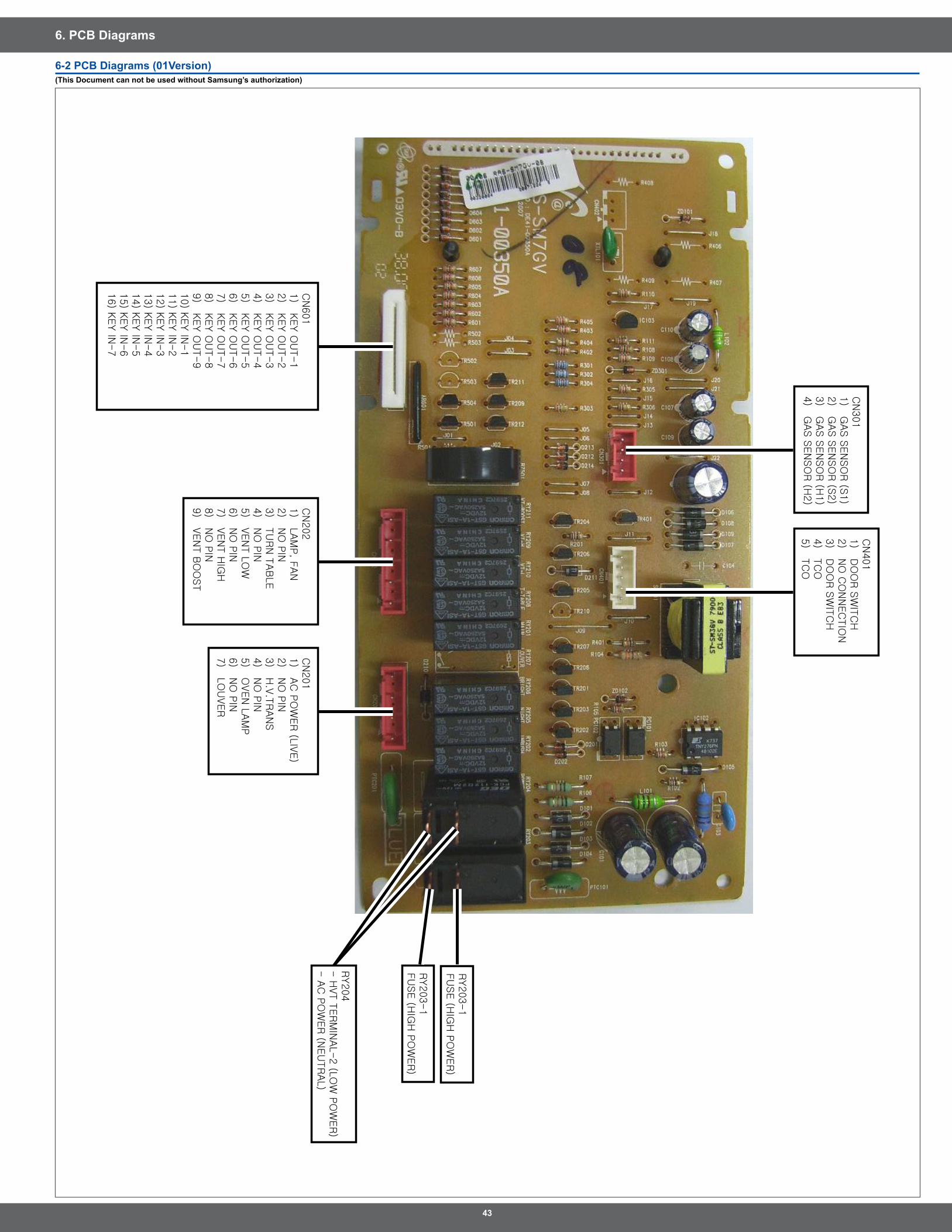
43
6. PCB Diagrams
6-� PCB Diagrams (01Version)(This Document can not be used without Samsung’s authorization)
CN
301
1) G
AS S
EN
SO
R (S
1)
2) G
AS S
EN
SO
R (S
2)
3) G
AS S
EN
SO
R (H
1)
4) G
AS S
EN
SO
R (H
2)
RY203-1
FU
SE (H
IGH
PO
WER)
RY203-1
FU
SE (H
IGH
PO
WER
)
RY204
- H
VT T
ER
MIN
AL-2 (L
OW
PO
WER)
- A
C P
OW
ER (N
EU
TR
AL)
CN
401
1) D
OO
R S
WIT
CH
2) N
O C
ON
NEC
TIO
N3) D
OO
R S
WIT
CH
4) T
CO
5) T
CO
CN
201
1) A
C P
OW
ER
(LIV
E)
2) N
O P
IN3) H
.V.T
RAN
S4) N
O P
IN5) O
VEN
LAM
P6) N
O P
IN7) L
OU
VER
CN
202
1) L
AM
P, F
AN
2) N
O P
IN3) T
UR
N T
AB
LE
4) N
O P
IN5) V
EN
T L
OW
6) N
O P
IN7) V
EN
T H
IGH
8) N
O P
IN9) V
EN
T B
OO
ST
CN
601
1) K
EY O
UT-1
2) K
EY O
UT-2
3) K
EY O
UT-3
4) K
EY O
UT-4
5) K
EY O
UT-5
6) K
EY O
UT-6
7) K
EY O
UT-7
8) K
EY O
UT-8
9) K
EY O
UT-9
10) K
EY IN
-1
11) K
EY IN
-2
12) K
EY IN
-3
13) K
EY IN
-4
14) K
EY IN
-5
15) K
EY IN
-6
16) K
EY IN
-7
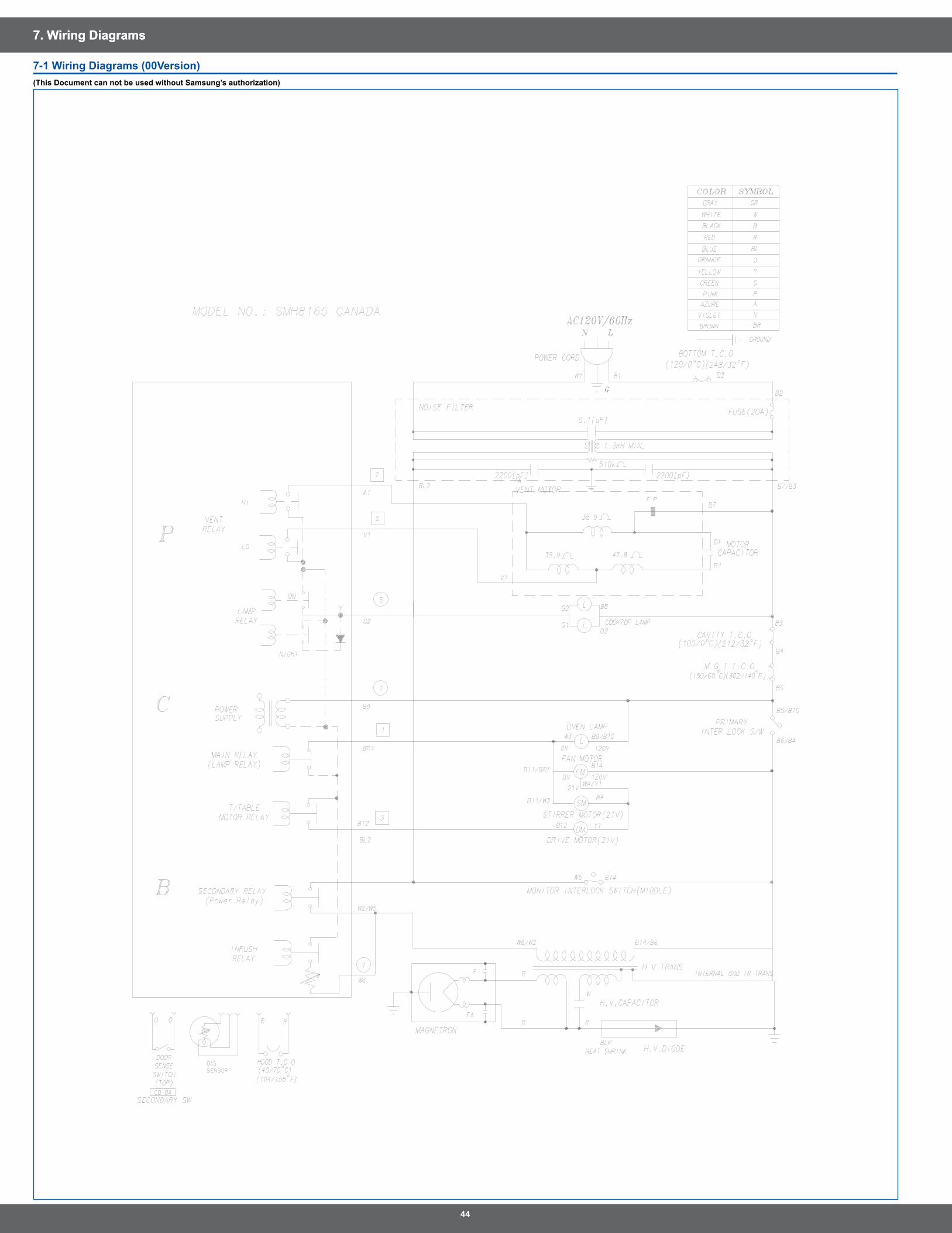
44
7. Wiring Diagrams7. Wiring Diagrams
7-1 Wiring Diagrams (00Version)(This Document can not be used without Samsung’s authorization)
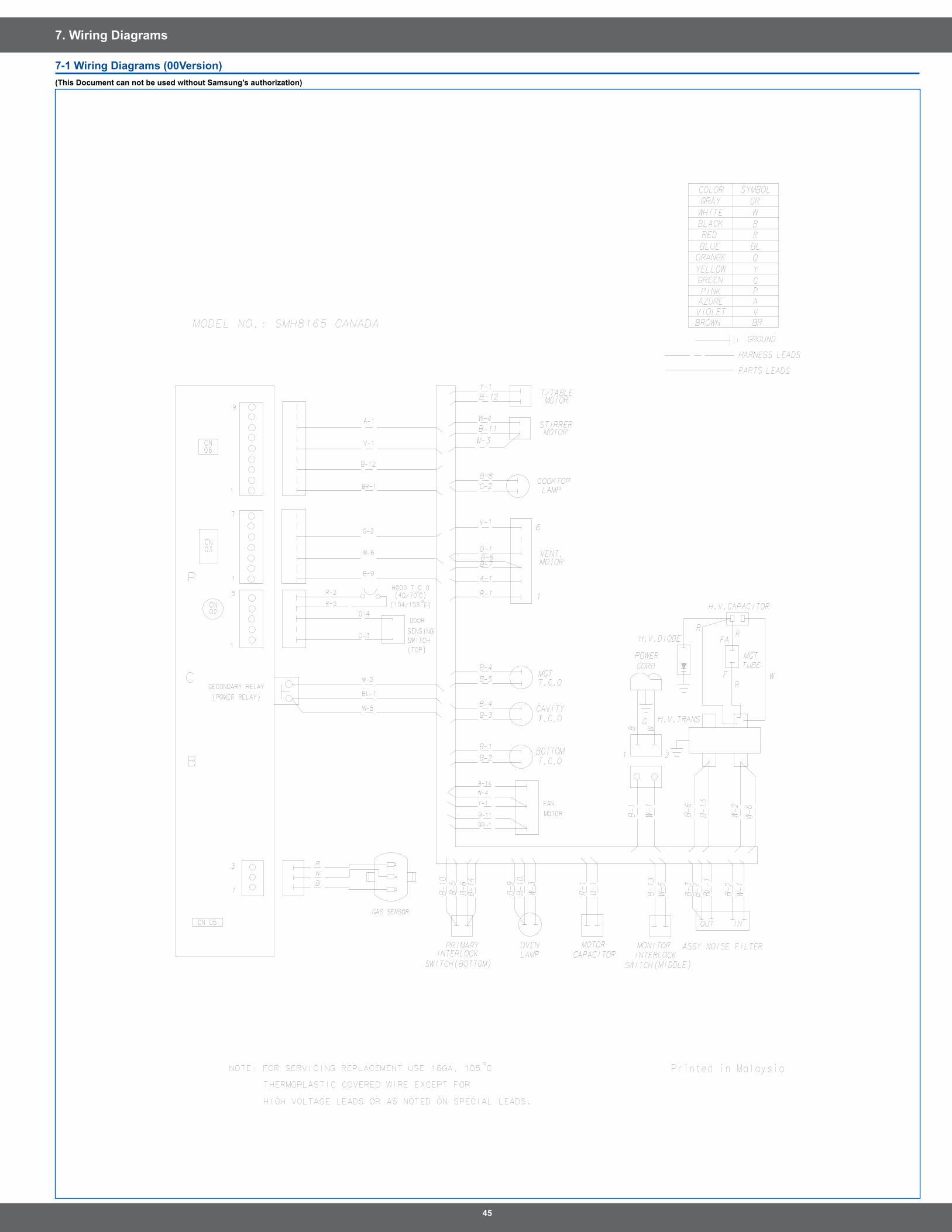
45
7. Wiring Diagrams
7-1 Wiring Diagrams (00Version)(This Document can not be used without Samsung’s authorization)
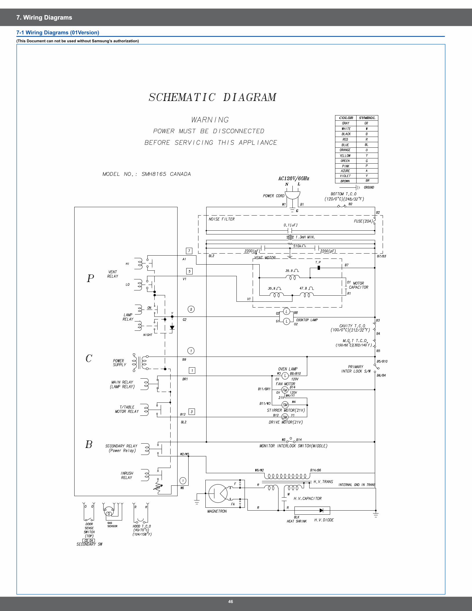
46
7. Wiring Diagrams7. Wiring Diagrams
7-1 Wiring Diagrams (01Version)(This Document can not be used without Samsung’s authorization)
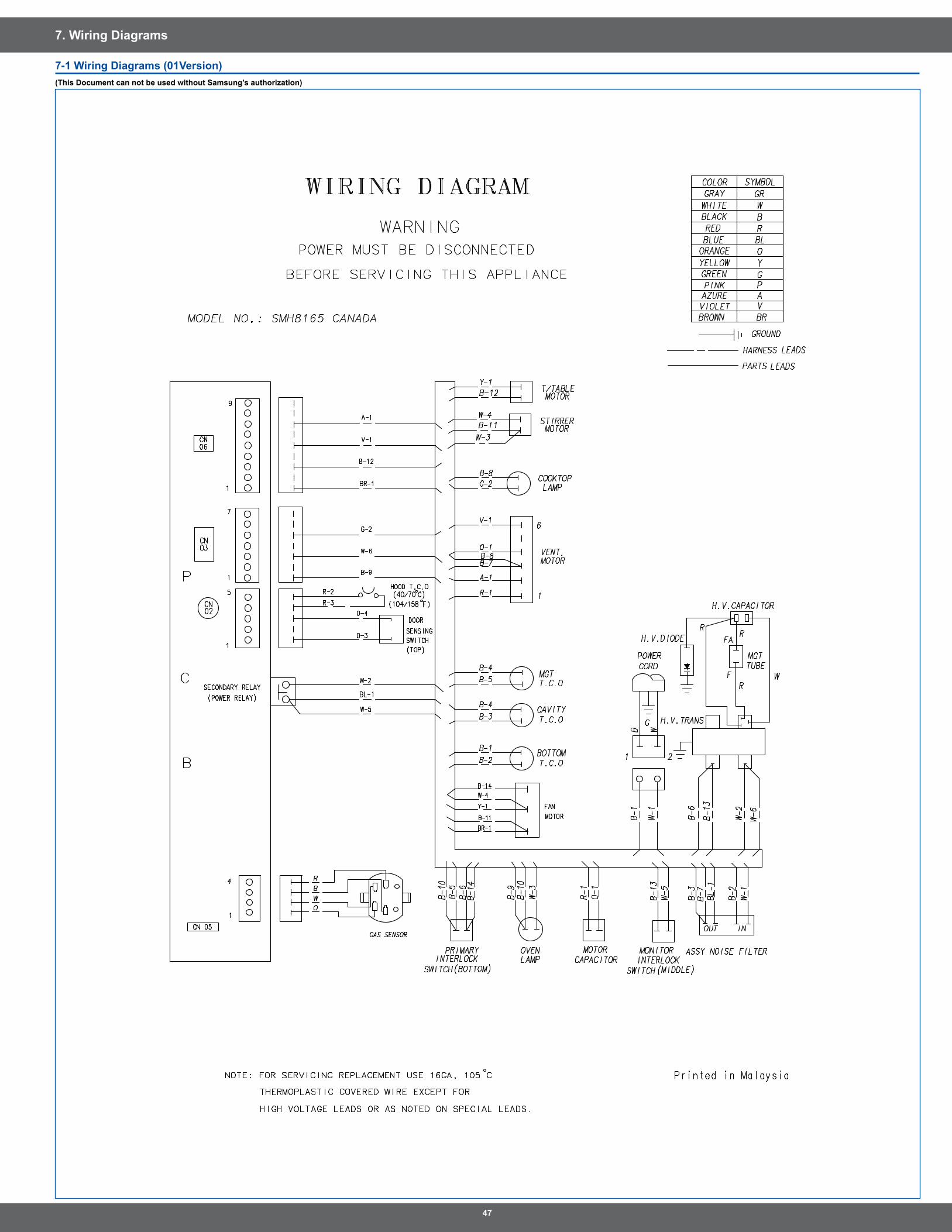
47
7. Wiring Diagrams
7-1 Wiring Diagrams (01Version)(This Document can not be used without Samsung’s authorization)
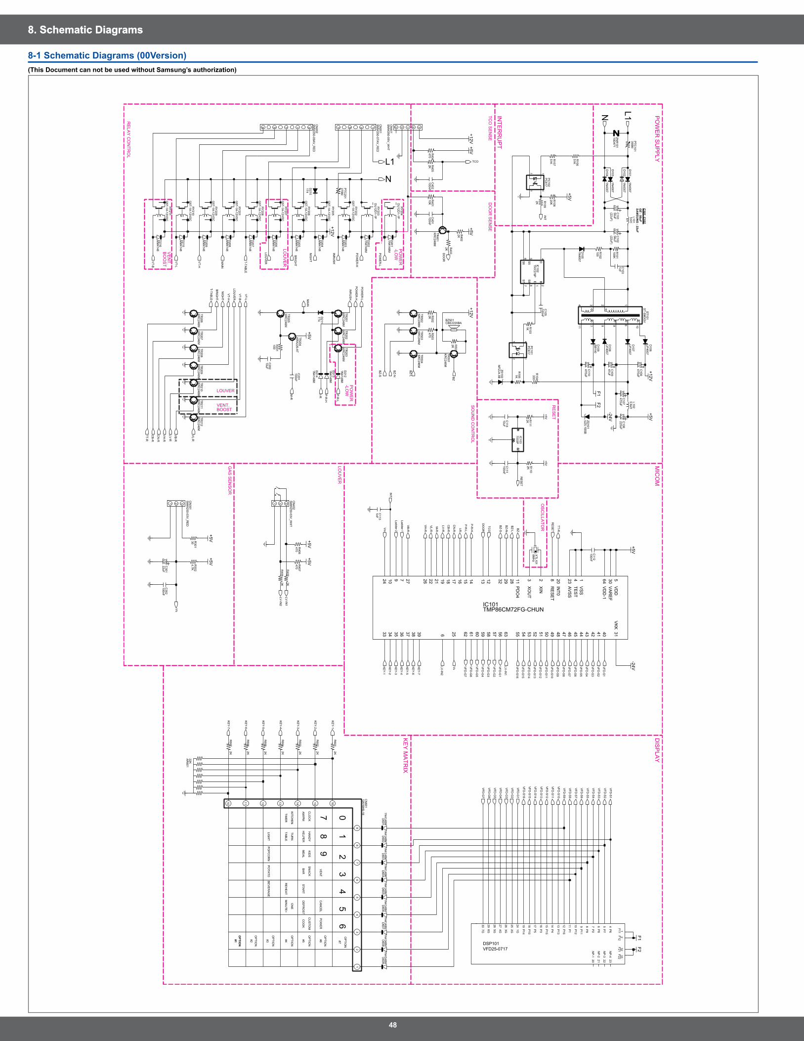
48
8. Schematic Diagrams8. Schematic Diagrams
8-1 Schematic Diagrams (00Version)(This Document can not be used without Samsung’s authorization)
MIC
OM
DIS
PLA
Y
KE
Y M
ATR
IX
VE
NT
CA
NC
EL
PO
WE
R
HA
ND
Y
HE
LPE
R
TUR
N
RE
HE
AT
PO
TATO
(22uF)
C101, C
102G
E : 56uFSA
MSU
NG
: 22uF
OP
TION
#7
PO
WE
R S
UP
PLY
STA
RT
OS
CILLA
TOR
ON
E
4
INTE
RR
UP
T
ME
AL
7
#1
OP
TION
OPTIO
N
1
(22uF)
5
8
CO
OK
GA
S S
EN
SO
R
BE
VE
RA
GE
LOU
VE
R
OP
TION
#2
3
TIME
R
OP
TION
SN
AC
K
BA
R
PO
PC
OR
N
OP
TION
AM
/PM
SO
UN
D C
ON
TRO
L
CLO
CK
#6
PO
WE
R-LO
W
PO
WE
R
TCO
SE
NS
E
TAB
LE
-LOW
LOU
VE
R
VE
NT.
BO
OS
T
LOUVER
KID
S
DO
OR
SE
NS
E
BOOST
9
VENT.
6
KITC
HE
N
CU
STO
M
#5
RE
LAY
CO
NTR
OL
RE
SE
T
DE
FRO
ST
LIGH
T
OP
TION
#4M
INU
TE+
#3
20
RY
209G
5T-1A-12V
DC
KR
C246M
TR201
1N4148M
D605
20K
KR
C246M
TR210
+5VR108
7 89 1011
ST-S
M3G
VS
T101
1234
6
43
12
G5T-1A
-12VD
CR
Y208
+5V
PC
817P
C101
D604
1N4148M
D102
1N4007
22KA
R601
MM
4148D
215
KR
C246M
TR207
D216
MM
4148
D602
1N4148M
RY
202G
5T-1A-12V
DC
2D
4
E1
5S
5
S6
6S
77 8
S8
+5V
D608
1N4148M
TNY
276PIC
102B
R501
MM
4148D
203
470R
404
2K
220uF
3.9uHL102
C108
1N4148M
D603
MTZJ4.3B
ZD102
C401
100nF
10D471
ZNR
101
CBE2220BABZ501
TR204
KR
A226-A
T
TR208
KR
C246M
D205
MM
4148
MM
4148D
204
470R
503
SB
140D
109
2K
D107
UF4007
-24V
R502
UF4007
D108
47uF1N
4007D
104
470uF
C109
1357
C110
SM
W250-07A
V_R
ED
CN
201
100nFC
112
KR
C246M
TR202
231
CN
402S
MW
250-03V_W
HT
R401
10K
R403
2K
KR
C246M
TR401
2K
RY
205G
5T-1A-12V
DC
+12V
R109
G5T-1A
-12VD
CR
Y210
TR205
KR
C246M
22uFC
301
R302
4.7KR
30130
100nFC
302
2KR
605
1mH
L101
1nFC
113
C102
56uF
C201
100nF
C111
100nF
KR
C246M
TR212
+12V
C202
10uF
100nFC
402
TR503
KR
C246M
R106
51K
PC
817P
C102
43
12
52C
N401
SM
W250-05V
_WH
T
341
+5V
F2+5V
470R
406
TR211
KR
C246M
330R
104
ZD101
UZ5.1B
SB
2K R402
KR
C246M
TR502
RY
206G
5T-1A-12V
DC
PTC
201270M
RY
201G
5T-1A-12V
DC
DU
12D1-1P
RY
204
8MH
zX
TL101
P9
D103
1N4007
NP
-4
11P
1
P10
18 9P
11
10P
12
13P
13
P14
19
P15
15 12P
16
7P
2
P3
16
P4
14
P5
17 4P
6
5P
7
6P
8
824
2G25
3G26
4G27
5G28
6G29
7G30
1F11
2F1232
F2133
F2220N
P-1
21N
P-2
22N
P-3
23
VFD25-0717DSP101
1G
TR209
KR
C246M
F2
56uFC
101
F1
+12V
R102
100
TR501
KR
C246M
MM
4148D
206
7033PIC
103
R111
2K
DG
ND
DG
ND
+5V
C114
10uF
C105
100nF
R409
2K
R110
2K
CN
301S
MW
250-03V_R
ED
1 2 3
2KR
408
-24V
F1
MM
4148D
208
59
D209
MM
4148
SM
W250-09A
V_R
ED
CN
202
317
1N4007
D101
R107
51K
2KR
607
R606
2K
G5T-1A
-12VD
CR
Y207
UF4007
D106
1nFC
103
+5V
+5V
100KR
101
D202
1N4148M
RY
203D
U12D
1-1P
R407
+5V
470uF
+5V
470
C107
D214
470uFC
106
11
RE
SE
T8
TES
T4
VA
RE
F30
VD
D5
VD
D-1
64
VK
K31
VS
S1
XIN
2
XO
UT
3
1N4148M
47 46 45 44 43 42 41 40639383736353433
PD
O4
62 61 60 59 58 57 56 63 55 54 53 52 51 50 49 48
1516179 277 212224
25
26 2829321819
IC101TMP86CM72FG-CHUN
AV
SS
23
INT0
2010 121314
TR206
KR
C246M
2KR
601
D210
1T4
1N4148M
D609
1N4148M
D201
+5V
1KR
105
+5V
D105
1N4007
1110
87
65
43
21
12516HS
-16C
N601
9
1615141312
1N4148M
D601
PTC
101390M
D211
1T4
R405
2K
KR
C246M
TR203
R201
100
R103
1K
TR504
KR
C246M
+12V
D213
1N4148M
RY
211G
5T-1A-12V
DC
D207
MM
4148
1N4148M
D607
D606
1N4148M
D212
1N4148M
2KR
603
R604
2K
R602
2K
VFD
-G4
VFD
-G3
VFD
-G2
VFD
-G1
Vs
VFD
-S10
VFD
-S7
VFD
-S6
VFD
-S15
VFD
-S8
VFD
-G7
VFD
-G6
VFD
-G5
LV-R
VB
-R
VT-B
VL-R
VT-L
N
VT-B
VT-L
L1
VFD
-S5
VFD
-S3
VFD
-S2
VFD
-S1
VFD
-S14
VFD
-S11
VFD
-S13
VFD
-S4
VFD
-S9
VFD
-S12
VFD
-S16
VT-H
VH
-R
VH
-R
RE
SE
T
VB
-R
INT
LV-IN
1
LV-IN
2
LOU
VE
R
Ladder-2
Vs
LV-R
LV-IN
1
INR
US
H
VL-R
LOU
VE
R
VFD
-G5
VFD
-G7
VFD
-S16
VFD
-S1
KE
Y-1
KE
Y-2
KE
Y-3
KE
Y-4
KE
Y-5
KE
Y-6
KE
Y-7
RE
SE
T
BZ-L
BZ-N
BZ-S B
Z
TCO
P-R
-L
CB
-R I-R
M-R
P-R
-H
CN
-R
DO
OR
Vm
TT-R
LV-IN
2
L1N
NIG
HT
PO
WE
R-L
PO
WE
R-L
P-R
-L
VT-H
INT
Ladder-1
VFD
-S2
VFD
-S3
VFD
-S4
VFD
-S5
VFD
-S6
VFD
-S7
VFD
-S8
VFD
-S9
VFD
-S10
VFD
-S11
VFD
-S12
VFD
-S13
VFD
-S14
VFD
-S15
VFD
-G6
VFD
-G1
VFD
-G2
VFD
-G3
VFD
-G4
BZ
BZ-N
BZ-L
INR
US
H
PO
WE
R-HM
AIN
TT-R
T-TAB
LE
P-R
-H
I-R
CB
-R
BR
IGH
T
CN
-R
PO
WE
R-H
NIG
HT
BR
IGH
T
T-TAB
LE
MA
IN
M-R
BZ-S
DO
OR
TCO
KE
Y-1
KE
Y-2
KE
Y-3
KE
Y-4
KE
Y-5
KE
Y-6
KE
Y-7
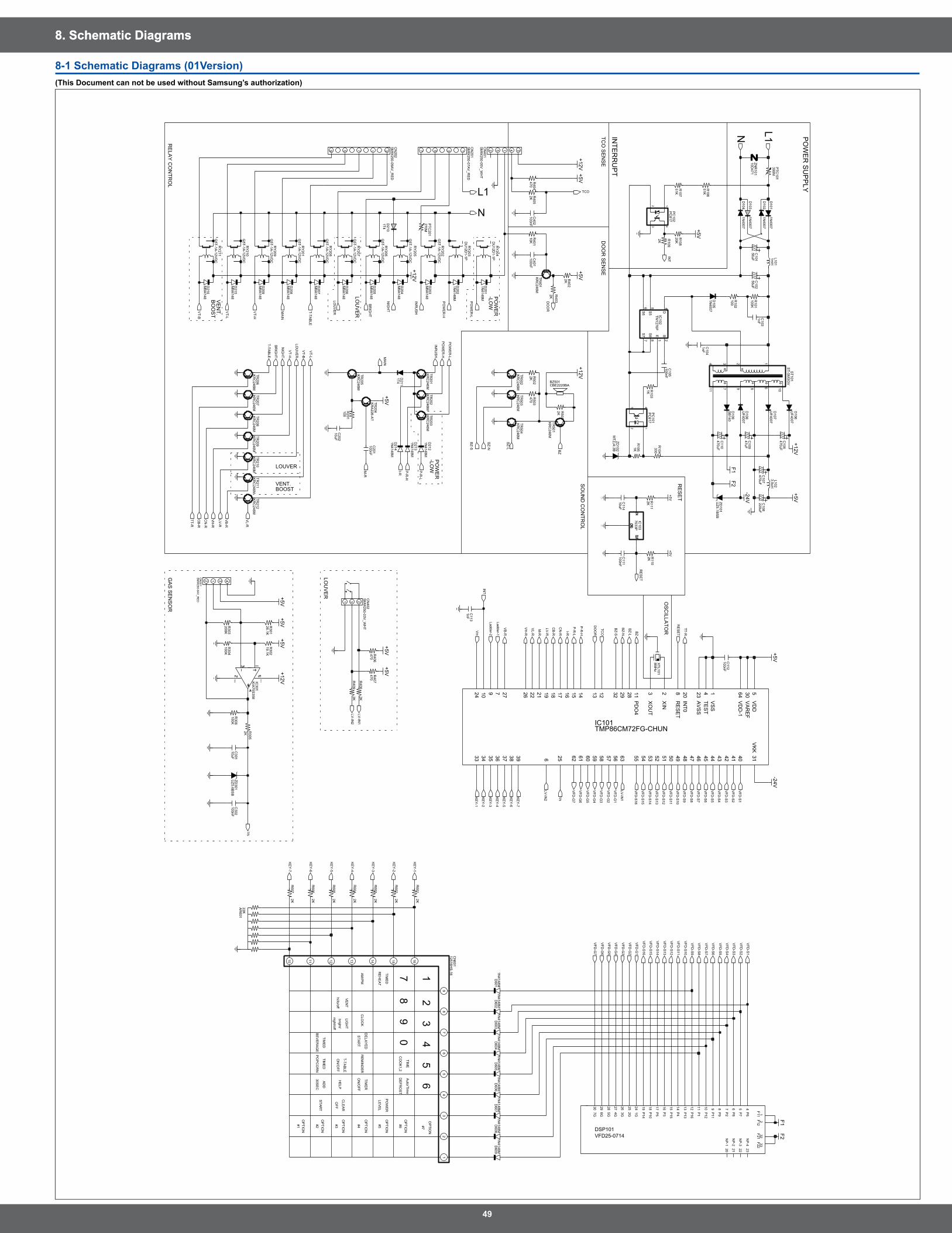
49
8. Schematic Diagrams8. Schematic Diagrams
8-1 Schematic Diagrams (01Version)(This Document can not be used without Samsung’s authorization)
RE
LAY
CO
NTR
OL
RE
SE
T
DE
FRO
ST
T-TAB
LE
OP
TION
#4O
N/O
FFA
M/P
M
VE
NT
CLO
CK
#6
PO
WE
R-LO
W
PO
WE
R
HE
LP
RE
MIN
DE
R
-LOW
LOU
VE
R
VE
NT.
BO
OS
T
LOUVER
DE
LAY
ED
OFF
TIME
D
VENT.BOOST
TCO
SE
NS
ED
OO
R S
EN
SE
SO
UN
D C
ON
TRO
L
6
TIME
DP
OW
ER
#5
OP
TION
#7
30SE
CS
TAR
T
OS
CILLA
TOR
TIME
R
TIME
D
night/off
STA
RT
CLE
AR
Auto/Tim
e
#1
OP
TION
#3
2
LIGH
T
hi/lo/off
4
7
PO
WE
R S
UP
PLY
INTE
RR
UP
T
LEV
EL
GA
S S
EN
SO
R
BE
VE
RA
GE
LOU
VE
RO
PTIO
N#2
3
RE
HE
AT
OP
TION
TIME
CO
OK
1,29
PO
PC
OR
N
OP
TION
8
bright/
OP
TION
1
ON
/OFF
0
5
AD
D
D214
11
RE
SE
T8
TES
T4
VA
RE
F30
VD
D5
VD
D-1
64
VK
K31
VS
S1
XIN
2
XO
UT
3
1N4148M
47 46 45 44 43 42 41 40639383736353433
PD
O4
62 61 60 59 58 57 56 63 55 54 53 52 51 50 49 48
1516179 277 212224
25
26 2829321819
IC101TMP86CM72FG-CHUN
AV
SS
23
INT0
2010 121314
TR206
KR
C246M
2KR
601
D210
1T4
1N4148M
D609
1N4148M
D201
100KR
306
2K R305
KR
C246M
TR502
2K R402
PTC
201270M
RY
206G
5T-1A-12V
DC
1nFC
103
100KR
101
D202
1N4148M
DU
12D1-1P
RY
204
8MH
zX
TL101
P8
8P
9
D103
1N4007
NP
-3
23N
P-4
11P
1
P10
18 9P
11
10P
12
13P
13
P14
19
P15
15 12P
16
7P
2
P3
16
P4
14
P5
17 4P
6
5P
7
6
1G24
2G25
3G26
4G27
5G28
6G29
7G30
1F11
2F1232
F2133
F2220N
P-1
21N
P-2
22
VFD25-0714DSP101
RY
203D
U12D
1-1P
R407
+5V
CN
301S
MW
250-04V_R
ED
2 1 3 4
470
470uF
+5V
C107
7033PIC
103
470uFC
106
DG
ND
DG
ND
+5V
C114
10uF
R111
2K
R303
1KR
105
+5V
200K
1N4007
R409
2K
D105
R110
2K
+5V
TR211
KR
C246M
470R
406
R302
26.1KR
30119.1K
330R
104
ZD101
UZ5.1B
SB
RY
201G
5T-1A-12V
DC
R201
100
65
43
21
C301
10uF
9
16151413121110
87
1N4148M
D601
12516HS
-16C
N601
D211
1T4
MM
4148D
206
PTC
101390M
F2
F1
+12V
TR209
KR
C246M
56uFC
101
R102
100
TR501
KR
C246M
20K
KR
C246M
TR201
+5VR108
11
KR
C246M
TR210
ST-S
M3G
VS
T101
1234
67 89 10
43
12
G5T-1A
-12VD
CR
Y208
R405
2K
PC
817P
C101
100nFC
402
C202
10uF
TR503
KR
C246M
2
R106
51K
PC
817P
C102
43
1
KR
C246M
TR207
D602
1N4148M
RY
202G
5T-1A-12V
DC
IC102
B2
D4
E1
5S
5
S6
6S
77 8
S8
+5V
D608
1N4148M
D203
TNY
276P
R501
MM
4148
470R
404
2K
220uF
3.9uHL102
C108
MTZJ4.3B
ZD102
D102
1N4007
C401
100nF
RY
209G
5T-1A-12V
DC
1N4148M
D605
MM
4148D
204
SB
140D
109
470R
503R
5022K
D107
UF4007
+5V
UF4007
D108
D604
1N4148M
1N4007
D104
22KA
R601
MM
4148D
215
D216
MM
4148
31
100nFC
112
CN
402S
MW
250-03V_W
HT
2
R403
2K
KR
C246M
TR401
R401
10K
RY
205G
5T-1A-12V
DC
+12V
R109
2KG5T-1A
-12VD
CR
Y210
1N4148M
D603
TR205
KR
C246M
100nFC
302
1mH
L101
C102
56uF10D
471ZN
R101
CBE2220BABZ501
TR204
KR
A226-A
T
TR208
KR
C246M
D205
MM
4148
VCC
VEE
+5V+5V
100KR
304
+12VIC301
KIA
75S358
UF4007
D106
-24V
+5V
+5V
C109
47uF
C110
470uF
SM
W250-07A
V_R
ED
CN
201
1357
KR
C246M
TR202
1N4148M
D607
D606
1N4148M
D212
1N4148M
4152
C105
100nF
F2
CN
401S
MW
250-05V_W
HT
3
+5V
UZ5.6B
SB
ZD301
1N4007
D101
R107
51K
2KR
607
R606
2K
G5T-1A
-12VD
CR
Y207
2KR
408
-24V
F1
MM
4148D
208
59
D209
MM
4148
SM
W250-09A
V_R
ED
CN
202
317
2KR
605
R604
2K 2KR
603
R602
2K
1nFC
113
C111
100nF
+12V
C201
100nF
KR
C246M
TR212
1nF
KR
C246M
TR203
R103
1K
C104
TR504
KR
C246M
+12V
D213
1N4148M
RY
211G
5T-1A-12V
DC
VFD
-G1
D207
MM
4148
VFD
-G6
VFD
-G5
VFD
-G4
VFD
-G3
VFD
-G2
VFD
-S5
VFD
-S3
VFD
-S2
VFD
-S1
VFD
-S14
VFD
-S11
VFD
-S13
VFD
-S4
VFD
-S9
VFD
-S12
VFD
-S16
VFD
-S10
VFD
-S7
VFD
-S6
VFD
-S15
VFD
-S8
VFD
-G7
RE
SE
T
VB
-R
LV-R
VB
-R
VT-B
VL-R
VT-L
N
VT-B
VT-L
L1
VL-R
LOU
VE
R
VT-H
VH
-R
VH
-R
INT
Vs
LV-IN
1
LV-IN
2
LOU
VE
R
Ladder-2
Vs
LV-R
LV-IN
1
INR
US
H
VFD
-G5
VFD
-G7
VFD
-S16
VFD
-S1
KE
Y-1
KE
Y-2
KE
Y-3
KE
Y-4
KE
Y-5
KE
Y-6
KE
Y-7
RE
SE
T
BZ-L
BZ-N
BZ-S B
Z
TCO
P-R
-L
CB
-R I-R
M-R
P-R
-H
CN
-R
DO
OR
Vm
TT-R
LV-IN
2
L1N
NIG
HT
PO
WE
R-L
PO
WE
R-L
P-R
-L
VT-H
INT
Ladder-1
VFD
-S2
VFD
-S3
VFD
-S4
VFD
-S5
VFD
-S6
VFD
-S7
VFD
-S8
VFD
-S9
VFD
-S10
VFD
-S11
VFD
-S12
VFD
-S13
VFD
-S14
VFD
-S15
VFD
-G6
VFD
-G1
VFD
-G2
VFD
-G3
VFD
-G4
BZ
BZ-N
BZ-L
INR
US
H
PO
WE
R-HM
AIN
TT-R
T-TAB
LE
P-R
-H
I-R
CB
-R
BR
IGH
T
CN
-R
PO
WE
R-H
NIG
HT
BR
IGH
T
T-TAB
LE
MA
IN
M-R
BZ-S
DO
OR
TCO
KE
Y-1
KE
Y-2
KE
Y-3
KE
Y-4
KE
Y-5
KE
Y-6
KE
Y-7

GSPN (Global Service Partner Network)Contry Web Site
North America service .samsungportal .com
Latin America latin .samsungportal .com
CIS cis .samsungportal .com
Europe europe .samsungportal .com
China china .samsungportal .com
Asia asia .samsungportal .com
Mideast & Africa mea .samsungportal .com
© Samsung Electronics Co ., Ltd . April . 2009 Printed in Korea Code No . : DE68-05370A