Basic Plasma Theory - METAL WEB NEWS
45
Copyright, 2000 Hypertherm, Inc. These materials cannot be reproduced in any form without the permission of Hypertherm, Inc. Basic Plasma Theory
Transcript of Basic Plasma Theory - METAL WEB NEWS

Copyright, 2000 Hypertherm, Inc.These materials cannot be reproduced in any form
without the permission of Hypertherm, Inc.
Basic Plasma Theory

PLA
SMA
BA
SIC
S
Copyright, 2000 Hypertherm, Inc.These materials cannot be reproduced in any form
without the permission of Hypertherm, Inc.
Basic Plasma Theory
To achieve optimum performance of your plasma cutting system it is necessary to first understand the plasma process.
Before we can do that, it is important to understand just what plasma is. Plasma is a state of matter. In fact, plasma is the most abundant form of matter in the universe.

PLA
SMA
BA
SIC
S
Copyright, 2000 Hypertherm, Inc.These materials cannot be reproduced in any form
without the permission of Hypertherm, Inc.
The “Perfect” Cut
All customers cutting metal are looking for essentially the same thing - THE PERFECT CUT. The perfect cut would have the following properties:
• Square angle
• No metallurgical changes
• No kerf

PLA
SMA
BA
SIC
S
Copyright, 2000 Hypertherm, Inc.These materials cannot be reproduced in any form
without the permission of Hypertherm, Inc.
Metal Cutting Methods
Unfortunately, this is not a perfect world! All metal cutting methods have advantages and disadvantages. Fundamentally, all metal cutting processes on the market today fall into one of three categories:
• Chemical
• Thermal
• Mechanical
• Thermal-Chemical
-Oxy-Fuel
-Plasma (that does not use air or Oxygen)
-Sawing,punching,nibbling,abrasive water jet,shearing
-Air or Oxy-plasma

PLA
SMA
BA
SIC
S
Copyright, 2000 Hypertherm, Inc.These materials cannot be reproduced in any form
without the permission of Hypertherm, Inc.
Plasma:“The Fourth State of Matter”
Operation

PLA
SMA
BA
SIC
S
Copyright, 2000 Hypertherm, Inc.These materials cannot be reproduced in any form
without the permission of Hypertherm, Inc.
We understand the first three states of matter to be solid, liquid, and gas. For the most commonly known substance, H2O (water), these states are ice, water, and steam.
solid liquid gas
The States of Matter

PLA
SMA
BA
SIC
S
Copyright, 2000 Hypertherm, Inc.These materials cannot be reproduced in any form
without the permission of Hypertherm, Inc.
When energy, in the form of heat, is applied to ice, the ice melts becoming water. The H2O transforms from the solid state, ice, to the liquid state, water.
solid liquid
The States of Matter

PLA
SMA
BA
SIC
S
Copyright, 2000 Hypertherm, Inc.These materials cannot be reproduced in any form
without the permission of Hypertherm, Inc.
When more heat is applied to the water, the water vaporizes becoming steam. The H2O transforms from the liquid state, water, to the gas state, steam (H2 & O2).
liquid gas
The States of Matter

PLA
SMA
BA
SIC
S
Copyright, 2000 Hypertherm, Inc.These materials cannot be reproduced in any form
without the permission of Hypertherm, Inc.
Finally, when additional heat is applied to the individual gases, the gases ionize. The ionization of the gases is the final change in states. The gases are now in an electrically conductive state called a plasma.
gas plasma
The States of Matter

PLA
SMA
BA
SIC
S
Copyright, 2000 Hypertherm, Inc.These materials cannot be reproduced in any form
without the permission of Hypertherm, Inc.
This often overlooked “fourth state of matter” is called PLASMA. This ionized gas with its current carrying properties is the fundamental basis on which all plasma systems operate.
The 4th State of Matter

PLA
SMA
BA
SIC
S
Copyright, 2000 Hypertherm, Inc.These materials cannot be reproduced in any form
without the permission of Hypertherm, Inc.
One example of plasma, as seen in nature, is lightning. Just like a plasma torch, the lightning moves electricity from one place to another. In lightning, gases in the air are the ionization gases.
Plasma in Nature

PLA
SMA
BA
SIC
S
Copyright, 2000 Hypertherm, Inc.These materials cannot be reproduced in any form
without the permission of Hypertherm, Inc.
Plasma cutting is a process that utilizes an optimized nozzle orifice
to constrict an electrically charged
ionized gas…...so that it can be used to melt and
sever sections of electrically conductive
metals. ( + )
Nozzle
Work Piece
Plasma Cutting
Electrode

PLA
SMA
BA
SIC
S
Copyright, 2000 Hypertherm, Inc.These materials cannot be reproduced in any form
without the permission of Hypertherm, Inc.
An electrically conductive gas (plasma) is used to transfer negative energy supplied by an electrical power source from a plasma torch to the material being cut.
The torch serves as the holder for the consumable parts and provides cooling (either gas or water) to these parts.
The nozzle and electrode constrict and maintain the plasma jet.
The Plasma Torch

PLA
SMA
BA
SIC
S
Copyright, 2000 Hypertherm, Inc.These materials cannot be reproduced in any form
without the permission of Hypertherm, Inc.
Sequence of Operation
In order to understand how the plasma arc is generated…..we need to understand the basic functions of the four major system components of every plasma cutting system:
•Power Supply•Start Circuit
•Gas Flow Control•Torch

PLA
SMA
BA
SIC
S
Copyright, 2000 Hypertherm, Inc.These materials cannot be reproduced in any form
without the permission of Hypertherm, Inc.
Component AnalysisPower Supply
•Produces constant current pure DC output.
•Houses the control circuitry for the proper sequencing of the entire system.
•Houses the cooling system for the torch.

PLA
SMA
BA
SIC
S
Copyright, 2000 Hypertherm, Inc.These materials cannot be reproduced in any form
without the permission of Hypertherm, Inc.
Component AnalysisRHF Console
Houses water and gas plumbing and related control devices as well as the high frequency starting circuit. The remote high frequency starting circuit permits more effective electrical noise shielding and allows the power supply to be installed up to 200 feet from the torch.

PLA
SMA
BA
SIC
S
Copyright, 2000 Hypertherm, Inc.These materials cannot be reproduced in any form
without the permission of Hypertherm, Inc.
Component AnalysisGas Console
• Houses metering and solenoid valves for shield and plasma gases. The gas console interfaces with the plasma and shield gas supplies, the RHF Console, the Motor Valve Console and the Power Supply.
• Should be mounted in a convenient location for the operator

PLA
SMA
BA
SIC
S
Copyright, 2000 Hypertherm, Inc.These materials cannot be reproduced in any form
without the permission of Hypertherm, Inc.
Component AnalysisTorch
Houses the consumables. The torch is where the arc is generated and therefore is the most important piece of the puzzle.

PLA
SMA
BA
SIC
S
Copyright, 2000 Hypertherm, Inc.These materials cannot be reproduced in any form
without the permission of Hypertherm, Inc.
Sequence of Operation
The four major components, power supply, starting circuit,gas flow control, and torch….. allow for the following sequence of events that initiate the plasma cutting process:
– start signal– torch starting mechanism
– gas flow– pilot arc
– arc transfer

PLA
SMA
BA
SIC
S
Copyright, 2000 Hypertherm, Inc.These materials cannot be reproduced in any form
without the permission of Hypertherm, Inc.
A start signal is sent to the DC power supply. This simultaneously activates the Open Circuit Voltage (OCV) and the gas flow to thetorch.
280 Volts DC_
+
High Frequency
OFF
Gas Flow
Sequence of Operation

PLA
SMA
BA
SIC
S
Copyright, 2000 Hypertherm, Inc.These materials cannot be reproduced in any form
without the permission of Hypertherm, Inc.
After the gas flow stabilizes, a High Frequency circuit is activated. The HF breaks down between the electrode and the nozzle inside the torch and the arc causes the gas passing through it to become ionized.
280 Volts DC_
+
High Frequency
10KV 2MHz
High Frequency
Gas Flow
Sequence of Operation

PLA
SMA
BA
SIC
S
Copyright, 2000 Hypertherm, Inc.These materials cannot be reproduced in any form
without the permission of Hypertherm, Inc.
This electrically conductive gas creates a current path between the electrode and the nozzle and results in the formation of a pilot arc.
280 Volts DC_
+
High Frequency
10KV 2MHz
Gas Flow
Pilot Arc
Sequence of Operation

PLA
SMA
BA
SIC
S
Copyright, 2000 Hypertherm, Inc.These materials cannot be reproduced in any form
without the permission of Hypertherm, Inc.
280 Volts DC_
+
High Frequency
OFF
Gas Flow
Plasma Arc
When the pilot arc is brought into contact with the workpiece, it will attach to the workpiece. The plasma arc melts the metal, and the high velocity gas removes the molten material.
Sequence of Operation

PLA
SMA
BA
SIC
S
Copyright, 2000 Hypertherm, Inc.These materials cannot be reproduced in any form
without the permission of Hypertherm, Inc.
High Frequency• High voltage (5,000V -
10,000V), high frequency AC forms a spark between electrode and nozzle
• Gas is forced to flow through this spark, raising it to it’s ionization temperature
• This is an effective starting method, but generates electrical “noise” that may affect sensitive electronic equipment
Torch Starting Methods
PLA
SMA
BA
SIC
S
Copyright, 2000 Hypertherm, Inc.These materials cannot be reproduced in any form
without the permission of Hypertherm, Inc.
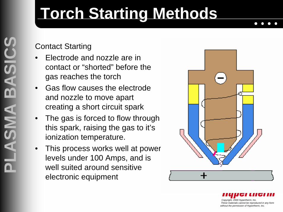
Contact Starting• Electrode and nozzle are in
contact or “shorted” before the gas reaches the torch
• Gas flow causes the electrode and nozzle to move apart creating a short circuit spark
• The gas is forced to flow through this spark, raising the gas to it’s ionization temperature.
• This process works well at power levels under 100 Amps, and is well suited around sensitive electronic equipment
Torch Starting Methods

PLA
SMA
BA
SIC
S
Copyright, 2000 Hypertherm, Inc.These materials cannot be reproduced in any form
without the permission of Hypertherm, Inc.
Non-Shielded Parts IssuesDouble Arcing
During the pierce, droplets of the molten metal can form a conductive path to the nozzle, causing the nozzle to be at positive potential.This can cause a “path of least resistance” from the electrode to the nozzle to the plate known as a “double arc”. This can also occur if the nozzle contacts the plate during a cut.
Torch Shielding Technology

PLA
SMA
BA
SIC
S
Copyright, 2000 Hypertherm, Inc.These materials cannot be reproduced in any form
without the permission of Hypertherm, Inc.
Non-Shielded Parts IssuesNozzle Damage
Contact to work piece damage and blow-back of spatter during cutting damages the nozzle by pitting and ovaling the orifice.
normal ovaling
Torch Shielding Technology

PLA
SMA
BA
SIC
S
Copyright, 2000 Hypertherm, Inc.These materials cannot be reproduced in any form
without the permission of Hypertherm, Inc.
Shielded Front End• Nozzle is protected by
an electrically isolated shield
• Significantly reduces double arcing
• Prolongs parts life• Facilitates drag cutting
and template tracing• Dramatic improvement
in nozzle life
Torch Shielding Technology

PLA
SMA
BA
SIC
S
Copyright, 2000 Hypertherm, Inc.These materials cannot be reproduced in any form
without the permission of Hypertherm, Inc.
Shielded Front End Benefits• During hand torch cutting:
• Ease of operation• Easy template tracing• Great nozzle life• Lower cost of
operation
Torch Shielding Technology

PLA
SMA
BA
SIC
S
Copyright, 2000 Hypertherm, Inc.These materials cannot be reproduced in any form
without the permission of Hypertherm, Inc.
Shielded Front End Benefits• During mechanized torch
cutting:• Greater nozzle life• Lower cost of operation• Longer service life with
consistent cut quality• Thicker Pierce Capacity• Protects the nozzle from
occasional contact with plate.
Torch Shielding Technology

PLA
SMA
BA
SIC
S
Copyright, 2000 Hypertherm, Inc.These materials cannot be reproduced in any form
without the permission of Hypertherm, Inc.
Kerf:Opening created by the metal removed by the plasma arc. The width of the kerf is determined by:
• amperage• gases• nozzle orifice size• consumable condition• torch-to-work distance
Cutting Terms

PLA
SMA
BA
SIC
S
Copyright, 2000 Hypertherm, Inc.These materials cannot be reproduced in any form
without the permission of Hypertherm, Inc.
Dross:The resolidified metal on the bottom or top of the cut. Dross formation and it’s condition is determined by many factors:
• travel speeds• amperage• gases used• type and thickness of metal• torch-to-work distance• material surface coatings
Cutting Terms

PLA
SMA
BA
SIC
S
Copyright, 2000 Hypertherm, Inc.These materials cannot be reproduced in any form
without the permission of Hypertherm, Inc.
Lag Lines:These are the ripples on the cut face or surface. The more consistent the power produced by power supply is, the smoother the cut. Depending on the process, normal lag lines are curved and slanted at about 15° with proper speeds.
Cutting Terms

PLA
SMA
BA
SIC
S
Copyright, 2000 Hypertherm, Inc.These materials cannot be reproduced in any form
without the permission of Hypertherm, Inc.
Using a Plasma Torch on an X-Y Table
• Mounted on an XY Table, a plasma torch can be controlled within all variations of the plane.
• In this manner, an operator can either control or set up a program to control the movement of the torch.
Applications

PLA
SMA
BA
SIC
S
Copyright, 2000 Hypertherm, Inc.These materials cannot be reproduced in any form
without the permission of Hypertherm, Inc.
Using a Plasma Torch on a Punch Press
• Combining punch presses with plasma creates a dual functioning machine.
• Often, the punch operation punches out precision holes while the plasma cutting operation is used to cut out the large holes, shapes, and perimeter of the parts.
Applications

PLA
SMA
BA
SIC
S
Copyright, 2000 Hypertherm, Inc.These materials cannot be reproduced in any form
without the permission of Hypertherm, Inc.
Using a Plasma Torch on a Robotic Arm
• Robots are multi-axis tool manipulators that can provide three dimensional movement.
• A plasma torch may be mounted on a robotic arm to help ease the cutting of irregularly shaped materials.
Applications

PLA
SMA
BA
SIC
S
Copyright, 2000 Hypertherm, Inc.These materials cannot be reproduced in any form
without the permission of Hypertherm, Inc.
Produces superior cut edge squareness, narrower kerfwidth, and less heat affected zone (HAZ)
This technology involves super-constricting the arc, dramatically increasing energy density of the arc.
Best thickness range is from 18 gauge to 3/4”
High DefinitionTechnology
…Developed in the early 1990’s!
PLA
SMA
BA
SIC
S
Copyright, 2000 Hypertherm, Inc.These materials cannot be reproduced in any form
without the permission of Hypertherm, Inc.
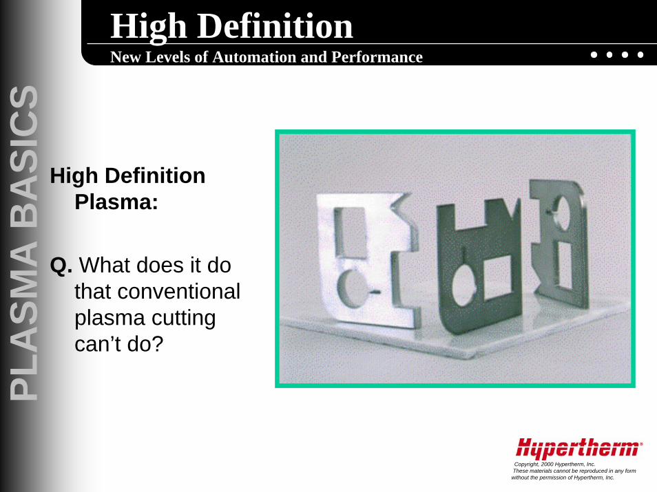
High Definition New Levels of Automation and Performance
High Definition Plasma:
Q. What does it do that conventional plasma cutting can’t do?

PLA
SMA
BA
SIC
S
Copyright, 2000 Hypertherm, Inc.These materials cannot be reproduced in any form
without the permission of Hypertherm, Inc.
High Definition New Levels of Automation and Performance
High Definition Plasma:
A. Conventional plasma systems typically produce better cut edge angularity as the material thickness increases….High Definition plasma produces excellent cut edge angularity through it’s entire cutting range.

PLA
SMA
BA
SIC
S
Copyright, 2000 Hypertherm, Inc.These materials cannot be reproduced in any form
without the permission of Hypertherm, Inc.
Superior Cut Quality & Tolerance
• Increased cut angle accuracy vs. conventional plasma….materials thinner than 3/8” are visibly sharper and more defined, while greater thicknesses (to 1”) will be produced with much tighter tolerances as compared to conventional plasma cutting processes.
• Typical angularity….1/8” steel= 0 degree bevel
High Definition New Levels of Automation and Performance

PLA
SMA
BA
SIC
S
Copyright, 2000 Hypertherm, Inc.These materials cannot be reproduced in any form
without the permission of Hypertherm, Inc.
Superior Cut Quality & Tolerance
• Narrow kerf width….typically 1/2 that of conventional plasma cutting.
• Very robust process……cutting is rarely affected by surface of metal, or metalurgical composition as other cutting processes are.
High Definition New Levels of Automation and Performance

PLA
SMA
BA
SIC
S
Copyright, 2000 Hypertherm, Inc.These materials cannot be reproduced in any form
without the permission of Hypertherm, Inc.
Superior Cut Quality & Tolerance
• Carbon steel is cut with Oxygen as the plasma gas producing a weldable, machineable, formable edge.
• HAZ is minimized…..typically less than .005”
• Virtually no dross on steel from gauge to 3/4”
High Definition New Levels of Automation and Performance

PLA
SMA
BA
SIC
S
Copyright, 2000 Hypertherm, Inc.These materials cannot be reproduced in any form
without the permission of Hypertherm, Inc.
Wide thickness and material range
• Aluminum cuts very well…..Nitrogen is used as the cutting gas……from gauge to 3/4”
• Thin stainless….gauge to 1/4”….is cut using Nitrogen with some edge oxidation
• Thicker stainless is cut using Nitrogen and Argon/Hydrogen with clean, weldable edges
High Definition New Levels of Automation and Performance

PLA
SMA
BA
SIC
S
Copyright, 2000 Hypertherm, Inc.These materials cannot be reproduced in any form
without the permission of Hypertherm, Inc.
Plasma Marking
Increased Process Flexibility
• Built-in ArcWriter plasma marking process for marking variety of metal surface. Same system can mark and cut further increasing productivity.
- light scoring & marking- heavy scoring & marking- punch marks or dimples

PLA
SMA
BA
SIC
S
Copyright, 2000 Hypertherm, Inc.These materials cannot be reproduced in any form
without the permission of Hypertherm, Inc.
Conclusion
• Todays Plasma Cutting Systems are the high productivity cutting solution for many applications.
• High Definition Plasma effectively fills the gap between Laser and Conventional plasma and oxyfuel processes with excellent tolerances, high cut speeds and low operating cost.
• Take a look at today’s plasma cutting capabilities!