Basic Logic Gates and De Morgan's Theorem Discussion D5.1 Appendix D.
30
Basic Logic Gates and De Morgan's Theorem Discussion D5.1 Appendix D
-
date post
20-Dec-2015 -
Category
Documents
-
view
214 -
download
0
Transcript of Basic Logic Gates and De Morgan's Theorem Discussion D5.1 Appendix D.

Basic Logic Gatesand De Morgan's Theorem
Discussion D5.1
Appendix D

Basic Logic Gates and Basic Digital Design
• NOT, AND, and OR Gates
• NAND and NOR Gates
• XOR and XNOR Gates
• DeMorgan’s Theorem
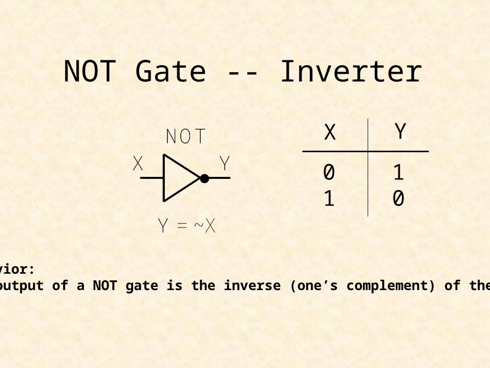
NOT Gate -- Inverter
X Y
01
10
X Y
Y
NOTX Y
Y = ~X
NOT
Behavior:The output of a NOT gate is the inverse (one’s complement) of the input

• Y = ~X (Verilog)• Y = !X (ABEL)• Y = not X (VHDL)• Y = X’• Y = X• Y = X (textook)• not(Y,X) (Verilog)
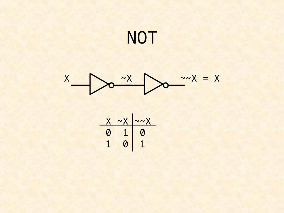
NOT
NOT
X ~X ~~X = X
X ~X ~~X0 1 01 0 1

AND GateAND
X
Y
Z
Z = X & Y
X Y Z0 0 00 1 01 0 01 1 1

• X & Y (Verilog and ABEL)• X and Y (VHDL)• X Y• X Y• X * Y• XY (textbook)• and(Z,X,Y) (Verilog)
AND
U
V

OR Gate
OR
X
YZ
Z = X | Y
X Y Z0 0 00 1 11 0 11 1 1

OR
• X | Y (Verilog)• X # Y (ABEL)• X or Y (VHDL)• X + Y (textbook)• X V Y• X U Y• or(Z,X,Y) (Verilog)

Y = ~Xnot(Y,X)
Summary of Basic Gates
NOT
X Y
01
10
X
YZ
X Y
X Y
Z
AND
OR
X Y Z0 0 00 1 01 0 01 1 1
X Y Z0 0 00 1 11 0 11 1 1
Z = X & Yand(Z,X,Y)
Z = X | Yor(Z,X,Y)
Any logic circuit can be created using only these three gates
Basic Logic Gates and Basic Digital Design
• NOT, AND, and OR Gates
• NAND and NOR Gates
• XOR and XNOR Gates
• DeMorgan’s Theorem
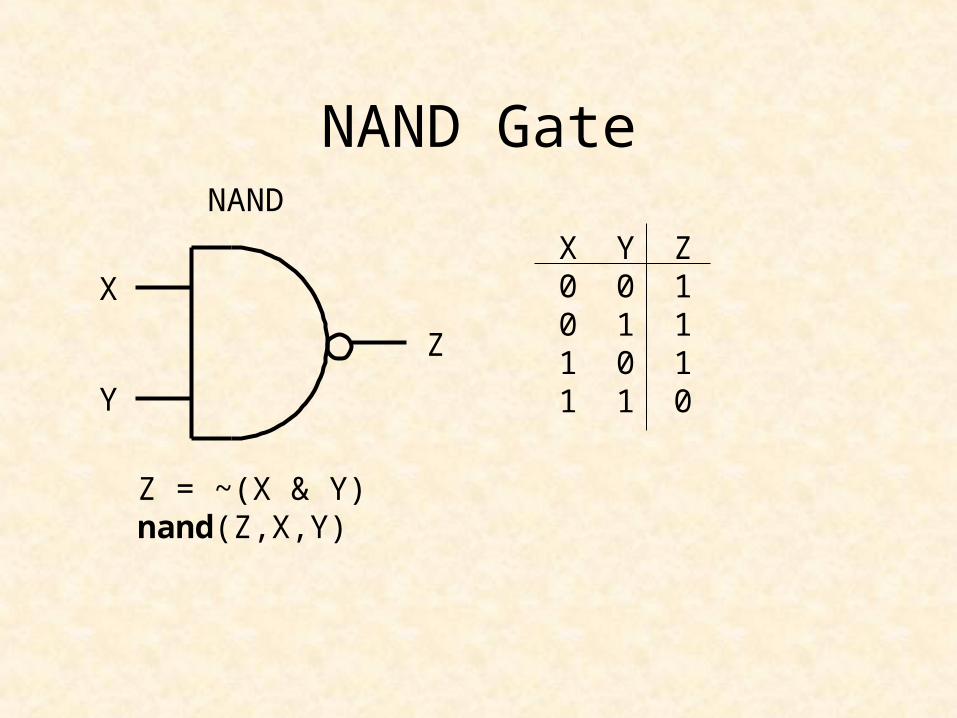
NAND GateNAND
X
Y
Z
X Y Z0 0 10 1 11 0 11 1 0
Z = ~(X & Y)nand(Z,X,Y)

NAND Gate
NOT-AND
X
Y
Z
W = X & Y
Z = ~W = ~(X & Y)
X Y W Z0 0 0 10 1 0 11 0 0 11 1 1 0
W

2-Input NAND GateNAND
X
YZ
Z = ~(X & Y)nand(Z,X,Y)
X Y Z0 0 10 1 11 0 11 1 0
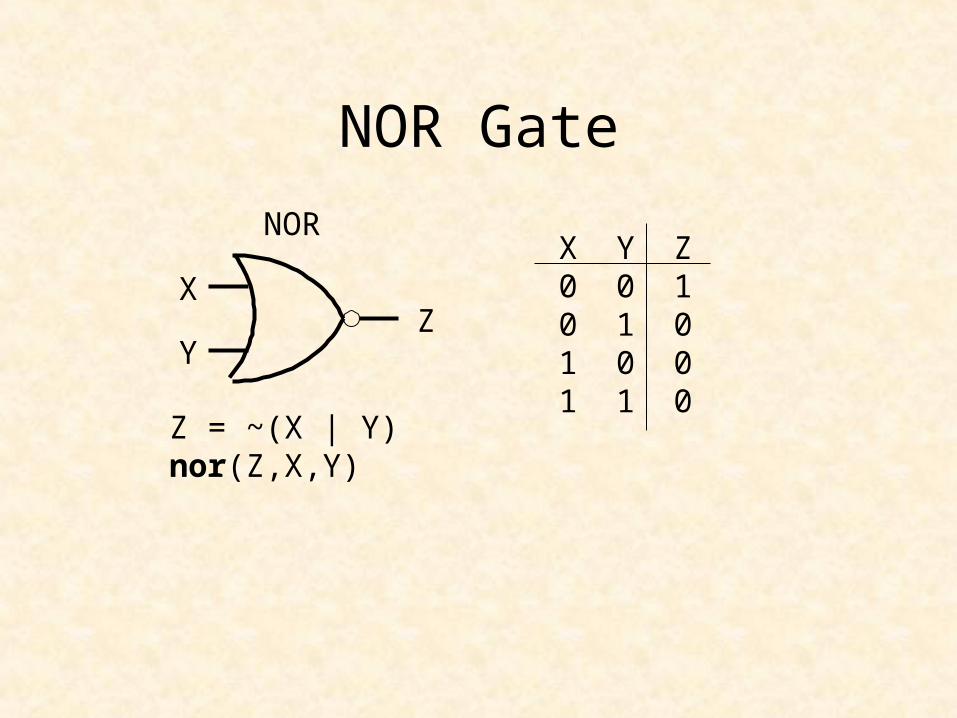
NOR Gate
NOR
X
YZ
X Y Z0 0 10 1 01 0 01 1 0
Z = ~(X | Y)nor(Z,X,Y)
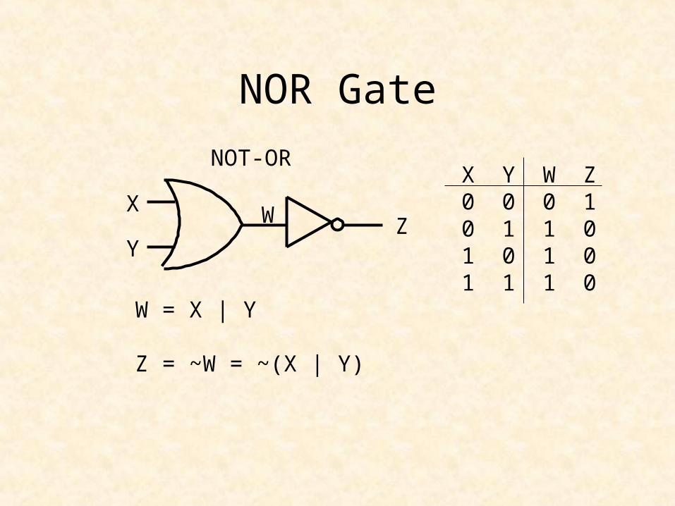
NOR Gate
NOT-OR
X
Y
W = X | Y
Z = ~W = ~(X | Y)
X Y W Z0 0 0 10 1 1 01 0 1 01 1 1 0
ZW

2 Input NOR Gate
NOR
XY
Z
Z = ~(X | Y)nor(Z,X,Y)
X Y Z0 0 10 1 01 0 01 1 0

Basic Logic Gates and Basic Digital Design
• NOT, AND, and OR Gates
• NAND and NOR Gates
• XOR and XNOR Gates
• DeMorgan’s Theorem

Exclusive-OR Gate
X Y ZXOR
X
YZ 0 0 0
0 1 11 0 11 1 0
Z = X ^ Yxor(Z,X,Y)
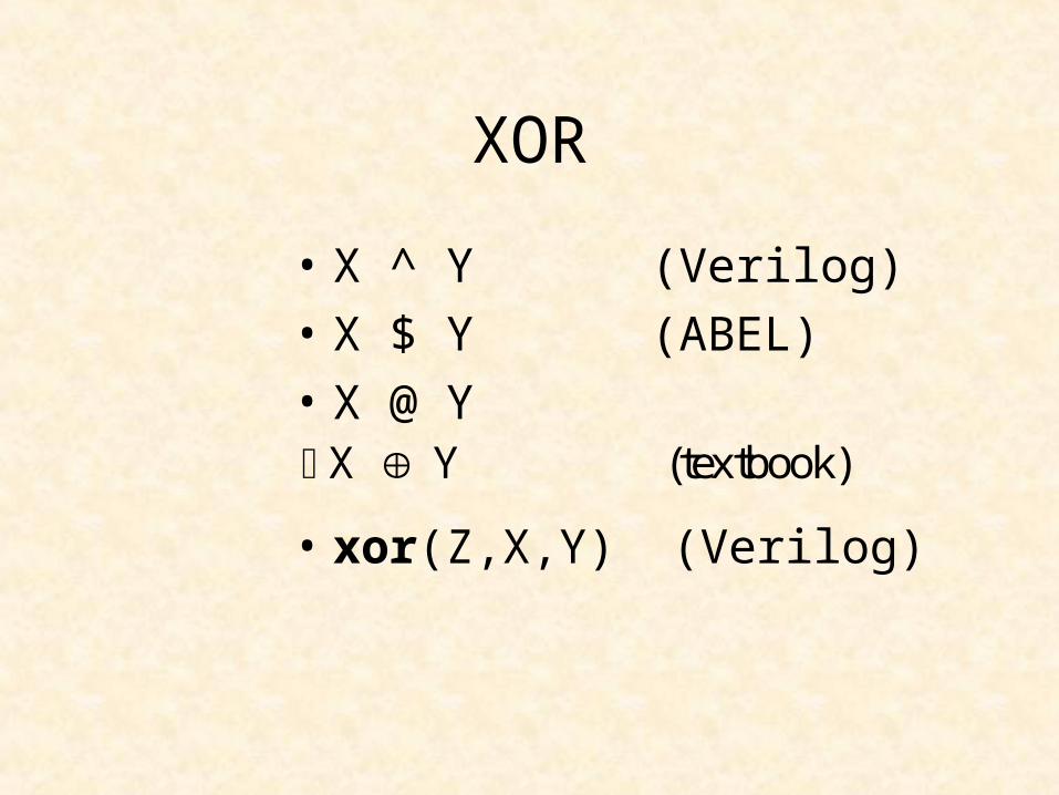
XOR
• X ^ Y (Verilog)• X $ Y (ABEL)• X @ Y
• xor(Z,X,Y) (Verilog)
X Y (textbook)
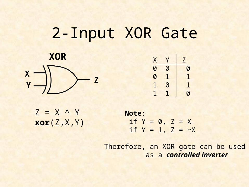
2-Input XOR Gate
XOR X Y Z0 0 00 1 11 0 11 1 0
Z = X ^ Yxor(Z,X,Y)
X Y
Z
Note: if Y = 0, Z = Xif Y = 1, Z = ~X
Therefore, an XOR gate can be used as a controlled inverter
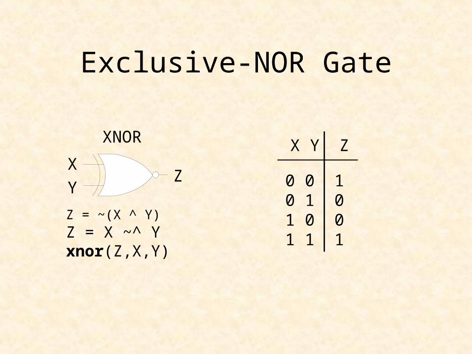
Exclusive-NOR Gate
X Y ZXNOR
X
YZ 0 0 1
0 1 01 0 01 1 1
Z = ~(X ^ Y)Z = X ~^ Yxnor(Z,X,Y)

XNOR
• X ~^ Y (Verilog)• !(X $ Y) (ABEL)• X @ Y
• xnor(Z,X,Y) (Verilog)
X Y

2-Input XNOR Gate
XNOR X Y Z0 0 10 1 01 0 01 1 1
Z = ~(X ^ Y)Z = X ~^ Yxnor(Z,X,Y)
Note: Z = 1 if X = Y
Therefore, an XNOR gate can be used as an equality detector
XY
Z

Basic Logic Gates and Basic Digital Design
• NOT, AND, and OR Gates
• NAND and NOR Gates
• XOR and XNOR Gates
• DeMorgan’s Theorem

NAND Gate
X
Y
X
Y
Z Z
Z = ~(X & Y) Z = ~X | ~Y
=
X Y W Z0 0 0 10 1 0 11 0 0 11 1 1 0
X Y ~X ~Y Z0 0 1 1 10 1 1 0 11 0 0 1 11 1 0 0 0

De Morgan’s Theorem-1
~(X & Y) = ~X | ~Y
• NOT all variables• Change & to | and | to &• NOT the result

NOR Gate
X
YZ
Z = ~(X | Y)
X Y Z0 0 10 1 01 0 01 1 0
X
YZ
Z = ~X & ~Y
X Y ~X ~Y Z0 0 1 1 10 1 1 0 01 0 0 1 01 1 0 0 0

De Morgan’s Theorem-2
~(X | Y) = ~X & ~Y
• NOT all variables• Change & to | and | to &• NOT the result

De Morgan’s Theorem
• NOT all variables
• Change & to | and | to &
• NOT the result
• --------------------------------------------
• ~X | ~Y = ~(~~X & ~~Y) = ~(X & Y)
• ~(X & Y) = ~~(~X | ~Y) = ~X | ~Y
• ~X & ~Y = ~(~~X | ~~Y) = ~(X | Y)
• ~(X | Y) = ~~(~X & ~Y) = ~X & ~Y