Deliverable D5.1 Requirements Elicitation
64
Project N o : FP7-231620 Project Acronym: HATS Project Title: Highly Adaptable and Trustworthy Software using Formal Methods Instrument: Integrated Project Scheme: Information & Communication Technologies Future and Emerging Technologies Deliverable D5.1 Requirements Elicitation Due date of deliverable: (T6) Actual submission date: 31 August 2009 Revision date: 30th March 2010 Start date of the project: 1st March 2009 Duration: 48 months Organisation name of lead contractor for this deliverable: FRG Revised version Integrated Project supported by the 7th Framework Programme of the EC Dissemination level PU Public X PP Restricted to other programme participants (including Commission Services) RE Restricted to a group specified by the consortium (including Commission Services) CO Confidential, only for members of the consortium (including Commission Services)
Transcript of Deliverable D5.1 Requirements Elicitation
Project No: FP7-231620
Project Acronym: HATS
Project Title: Highly Adaptable and Trustworthy Software using Formal Methods
Instrument: Integrated Project
Scheme: Information & Communication Technologies
Future and Emerging Technologies
Deliverable D5.1
Requirements Elicitation
Due date of deliverable: (T6)
Actual submission date: 31 August 2009
Revision date: 30th March 2010
Start date of the project: 1st March 2009 Duration: 48 months
Organisation name of lead contractor for this deliverable: FRG
Revised version
Integrated Project supported by the 7th Framework Programme of the EC
Dissemination level
PU Public X
PP Restricted to other programme participants (including Commission Services)
RE Restricted to a group specified by the consortium (including Commission Services)
CO Confidential, only for members of the consortium (including Commission Services)
Executive Summary:Requirements Elicitation
This document summarises deliverable D5.1 of project FP7-231620 (HATS), an Integrated Project supportedby the 7th Framework Programme of the EC within the FET (Future and Emerging Technologies) scheme.Full information on this project, including the contents of this deliverable, is available online at http://www.hats-project.eu.
Deliverable D5.1 presents the requirements for the HATS method elicited in Task 5.1. The requirementsare divided into methodological requirements and high level concerns. The methodological requirementsstem from different audiences and different perspectives and provide a high-level requirements view to theHATS methodology. The high level concerns are the result of analyzing different scenarios of three selectedcase studies of different profile, abstraction, size, and application area. Besides the description of theconcerns, the possible HATS support is already envisioned and mapped to the responsible work tasks. Thiswill simplify the validation in the next steps of Work Package 5.
List of Authors
Pablo Antonino (FRG)Ralf Carbon (FRG)Nikolay Diakov (FRH)Jan Schafer (UKL)Yannick Welsch (UKL)Peter Wong (FRH)
2
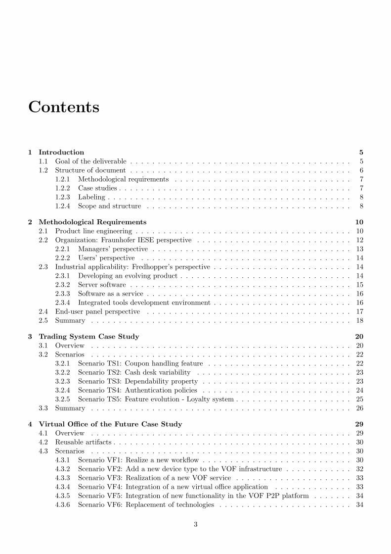
Contents
1 Introduction 51.1 Goal of the deliverable . . . . . . . . . . . . . . . . . . . . . . . . . . . . . . . . . . . . . . . . 51.2 Structure of document . . . . . . . . . . . . . . . . . . . . . . . . . . . . . . . . . . . . . . . . 6
1.2.1 Methodological requirements . . . . . . . . . . . . . . . . . . . . . . . . . . . . . . . . 71.2.2 Case studies . . . . . . . . . . . . . . . . . . . . . . . . . . . . . . . . . . . . . . . . . . 71.2.3 Labeling . . . . . . . . . . . . . . . . . . . . . . . . . . . . . . . . . . . . . . . . . . . . 81.2.4 Scope and structure . . . . . . . . . . . . . . . . . . . . . . . . . . . . . . . . . . . . . 8
2 Methodological Requirements 102.1 Product line engineering . . . . . . . . . . . . . . . . . . . . . . . . . . . . . . . . . . . . . . . 102.2 Organization: Fraunhofer IESE perspective . . . . . . . . . . . . . . . . . . . . . . . . . . . . 12
2.2.1 Managers’ perspective . . . . . . . . . . . . . . . . . . . . . . . . . . . . . . . . . . . . 132.2.2 Users’ perspective . . . . . . . . . . . . . . . . . . . . . . . . . . . . . . . . . . . . . . 14
2.3 Industrial applicability: Fredhopper’s perspective . . . . . . . . . . . . . . . . . . . . . . . . . 142.3.1 Developing an evolving product . . . . . . . . . . . . . . . . . . . . . . . . . . . . . . . 142.3.2 Server software . . . . . . . . . . . . . . . . . . . . . . . . . . . . . . . . . . . . . . . . 152.3.3 Software as a service . . . . . . . . . . . . . . . . . . . . . . . . . . . . . . . . . . . . . 162.3.4 Integrated tools development environment . . . . . . . . . . . . . . . . . . . . . . . . . 16
2.4 End-user panel perspective . . . . . . . . . . . . . . . . . . . . . . . . . . . . . . . . . . . . . 172.5 Summary . . . . . . . . . . . . . . . . . . . . . . . . . . . . . . . . . . . . . . . . . . . . . . . 18
3 Trading System Case Study 203.1 Overview . . . . . . . . . . . . . . . . . . . . . . . . . . . . . . . . . . . . . . . . . . . . . . . 203.2 Scenarios . . . . . . . . . . . . . . . . . . . . . . . . . . . . . . . . . . . . . . . . . . . . . . . 22
3.2.1 Scenario TS1: Coupon handling feature . . . . . . . . . . . . . . . . . . . . . . . . . . 223.2.2 Scenario TS2: Cash desk variability . . . . . . . . . . . . . . . . . . . . . . . . . . . . 233.2.3 Scenario TS3: Dependability property . . . . . . . . . . . . . . . . . . . . . . . . . . . 233.2.4 Scenario TS4: Authentication policies . . . . . . . . . . . . . . . . . . . . . . . . . . . 243.2.5 Scenario TS5: Feature evolution - Loyalty system . . . . . . . . . . . . . . . . . . . . . 25
3.3 Summary . . . . . . . . . . . . . . . . . . . . . . . . . . . . . . . . . . . . . . . . . . . . . . . 26
4 Virtual Office of the Future Case Study 294.1 Overview . . . . . . . . . . . . . . . . . . . . . . . . . . . . . . . . . . . . . . . . . . . . . . . 294.2 Reusable artifacts . . . . . . . . . . . . . . . . . . . . . . . . . . . . . . . . . . . . . . . . . . . 304.3 Scenarios . . . . . . . . . . . . . . . . . . . . . . . . . . . . . . . . . . . . . . . . . . . . . . . 30
4.3.1 Scenario VF1: Realize a new workflow . . . . . . . . . . . . . . . . . . . . . . . . . . . 304.3.2 Scenario VF2: Add a new device type to the VOF infrastructure . . . . . . . . . . . . 324.3.3 Scenario VF3: Realization of a new VOF service . . . . . . . . . . . . . . . . . . . . . 334.3.4 Scenario VF4: Integration of a new virtual office application . . . . . . . . . . . . . . 334.3.5 Scenario VF5: Integration of new functionality in the VOF P2P platform . . . . . . . 344.3.6 Scenario VF6: Replacement of technologies . . . . . . . . . . . . . . . . . . . . . . . . 34
3
HATS Deliverable D5.1 Requirements Elicitation
4.4 Summary . . . . . . . . . . . . . . . . . . . . . . . . . . . . . . . . . . . . . . . . . . . . . . . 35
5 Fredhopper Case Study 385.1 Overview . . . . . . . . . . . . . . . . . . . . . . . . . . . . . . . . . . . . . . . . . . . . . . . 385.2 Scenarios . . . . . . . . . . . . . . . . . . . . . . . . . . . . . . . . . . . . . . . . . . . . . . . 39
5.2.1 Scenario FP1: Correctness of sequential programs . . . . . . . . . . . . . . . . . . . . 405.2.2 Scenario FP2: Integration of a new feature component in FAS . . . . . . . . . . . . . 435.2.3 Scenario FP3: Test system provisioning . . . . . . . . . . . . . . . . . . . . . . . . . . 465.2.4 Scenario FP4: Concurrency . . . . . . . . . . . . . . . . . . . . . . . . . . . . . . . . . 495.2.5 Scenario FP5: Using third party library . . . . . . . . . . . . . . . . . . . . . . . . . . 515.2.6 Scenario FP6: Performance . . . . . . . . . . . . . . . . . . . . . . . . . . . . . . . . . 54
5.3 Summary . . . . . . . . . . . . . . . . . . . . . . . . . . . . . . . . . . . . . . . . . . . . . . . 56
6 Summary 59
Bibliography 61
Glossary 63
4
Chapter 1
Introduction
As pointed out in the project proposal, in HATS [17] we aim to develop a methodological and tool frame-work achieving not merely far-reaching automation in maintaining dynamically evolving software, but anunprecedented level of trust by replacing informal processes with rigorous analyzes based on formal methods.Furthermore, the HATS framework and methodology aim at enabling organizations to produce trustworthysoftware that supports adaptation. The methodology takes an empirically successful, yet informal softwaredevelopment paradigm and puts it on a formal basis. In HATS, we plan to turn the software product fam-ily (SWPF) development into a rigorous approach. Specifically, HATS focuses on product line engineering(PLE) [25], i.e. a development approach to produce products as part of a product family based on strategicand pro-active reuse of available components.
The technical core of the framework consists of an Abstract Behavioral Specification language whichallows precise description of SWPF features and components and their instances. Such level of descrip-tion allows analysis of various system properties related to trustworthiness, for instance, security or per-formance [6], and enable new opportunities in code generation, automatic product derivation etc. Theframework also provides extensive tool and method automation support to its users.
The project’s work packages one, two, three and four focus on developing various aspects of the HATSframework and methodology. The fifth work package (WP5) focuses on producing input to the other packagesto steer their results in the right direction. The WP5 includes execution of case studies to provide the finalevaluation of the degree of success of the HATS framework and methodology.
Within the HATS project, we opt for a research method based on continuous empirical evaluation ofthe project results throughout the project execution. Specifically we use an iterative approach, such thatat every step of the process, work package members would consider scenarios and requirements as startingpoints to develop the framework core, extensions and tooling. Furthermore, at every step of the processwe challenge the intermediate results by evaluating them against a criteria of requirements, preferably viacontrolled experimentations. This allows for early feedback and continuous improvement. Therefore, WP5has the important role to provide input that directs the work of other work packages, and the importantrole to validate results. In order to fulfill this goal, WP5 defines the following working tasks: Require-ments Elicitation (Task 5.1), Evaluation of Core Framework (Task 5.2), Evaluation of Modeling (Task 5.3),and Evaluation of Tools and Techniques (Task 5.4). In particular, this document presents results fromRequirements Elicitation.
1.1 Goal of the deliverable
This document presents deliverable D5.1, which contains the results from initial RequirementsElicitation (Task 5.1). In Task 5.1 we gather requirements in the form of detailed scenarios fromselected case studies, and identify general methodological concerns. Requirements Engineering inD5.1 is driven by the owners of the example case studies used in HATS. In particular, FRH andFRG bring in requirements from their industrial perspectives.
5
HATS Deliverable D5.1 Requirements Elicitation
The main goals of this document are as follows:
1. We study the general requirements of the HATS methodology. Specifically we collect high-level method-ological requirements from both industrial and research perspectives. In particular from the industrialperspective, we study how the HATS methodology may be integrated to existing development andsupport processes, while from the research perspective, we investigate how existing methodologicalchallenges, which arise in the scientific areas in which the HATS consortium is specialized, may beaddressed.
2. We have interviewed members of the end user panel of the HATS project. End user panel is composedof representatives of external companies interested in the HATS technology. In this document wepresent an evaluation of these interviews in the context of HATS methodology.
3. We provide three case studies, which differ in profile, abstraction, size and application area. Specificallywe have chosen an academic case study of a trading system for handling sales in supermarkets [27, 10];a case study of the Virtual Office of the Future [30] for supporting seamless execution of office tasksindependent of the office workers’ physical location, and an industrial case study on Fredhopper’sserver-based software systems [15] providing search and merchandising IT services to e-Commercecompanies.
4. Through each case study, we investigate several scenarios, and for each scenario, we present a concreteexample detailing the typical steps in the development and support process of the software systemdescribed in the case studies. We then identify technical concerns that arise from the concrete examplesand associate them to corresponding tasks from technical work packages 1 to 4, the result of whichwould address these concerns1.
We now give details on how requirements and concerns identified in this deliverable are used throughoutthe HATS project.
The methodological requirements are used to guide the development of the HATS methodology in Task1.1 as well as to guide the integration of different modeling techniques and tool support into the developmentmethod. These requirements will also be used to evaluate on the effectiveness of the methodology. Conse-quently these requirements will help the validation process (Tasks 5.2, 5.3 and 5.4) to provide constructivefeedback to the technical work tasks for further improvements.
In Task 5.2 we will study the methodological requirements in more detail and in particular we willinvestigate suitable evaluation strategies with these requirements. These strategies will then be appliedthroughout the validation process, starting with the validation of milestone M1 of the HATS project as partof Task 5.2.
Through various scenarios from the case studies this deliverable identifies high-level concerns that shouldbe addressed by the technologies delivered by the project’s work tasks. We will carry out extensive analysisto further refine these concerns in Task 5.2. The analysis will be carried out in close cooperation withpartners of individual work tasks. In Task 5.2 we aim also to define suitable evaluation methods and criteriafor each concern. These results will then be used to evaluate results of each work task as well as to guidethe validation process in WP5, starting with the validation of milestone M1 of the HATS project as part ofTask 5.2.
1.2 Structure of document
In this section we present the structure of this deliverable and provide the necessary detail to assist readersnavigating through this deliverable; we also highlight the scope of the requirements and concerns identifiedin this deliverable. A summary of this deliverable is provided in Chapter 6.
1Detailed requirements analysis of scenarios will be conducted in Task 5.2 together with members of the technical workpackages
6
HATS Deliverable D5.1 Requirements Elicitation
1.2.1 Methodological requirements
In Chapter 2 we describe requirements of the HATS methodology in the context of industry and research.
Industry
In the context of industry, we used three main sources for gathering methodological requirements – Firstis through the understanding of stakeholders’ needs in the development and support process of softwaresystems. Stakeholders in this process includes the managers that would have to decide on the adoption ofthe HATS method as well as the users such as software developers and support specialists, which would applythe HATS method to their daily work. Second is through examination of the most distinctive characteristicsof the software production method employed by the Fredhopper consortium member. Third is through theevaluation of the interviews with members of the end user panel.
Research
In the context of research, we focus on methodological requirements from product line engineering [25].Specifically we study the principle and foundation of product line engineering methodology and deriverequirements of the HATS methodology in the context of product line engineering.
1.2.2 Case studies
In Chapters 3, 4 and 5, we study the cases chosen as the sources of requirement elicitation of the HATSproject as well as the target where the evaluation of results produced from the project would be carriedout. Specifically Chapter 3 presents the case study of the trading system for handling sales in supermarkets,Chapter 4 presents the case study of the Virtual Office of the Future, and Chapter 5 presents the industrialcase study on Fredhopper’s server-based software systems. Here we describe the structure of each case studyin these chapters.
Structure of case studies
We format each case study using the following structure:
1. We informally introduce the functionality and the architecture of the software systems in question.This includes description of individual components of the systems and their interaction relationship.We then briefly overview each scenario and the technical concerns the scenario would identify.
2. We divide each scenario section into subsections. In each subsection we present the content in thefollowing format:
(a) Description of the scenario, its relationship to the software system in question and the type ofconcerns it aims to identify;
(b) A concrete example of the scenario. These are procedural steps, which reflect or portray the wayin which the software system is developed, used and maintained in the context of the scenario.For each step, a single instance of the procedure may be provided to help work package membersto understand the scenario.
(c) Concerns identified from the scenario. These are technical issues, which may be addressed bythe HATS framework for improving qualities of the software system, which include correctness,evolvability, trustworthiness and effective resource consumption, as well as the efficiency of thedevelopment and support process of the software system. We associate each concern with one ormore work tasks in the HATS project when possible.
3. We provide a summary of our presentation of the case study and tabulate the association of concernswith work tasks in the HATS project.
7
HATS Deliverable D5.1 Requirements Elicitation
1.2.3 Labeling
Methodological requirements
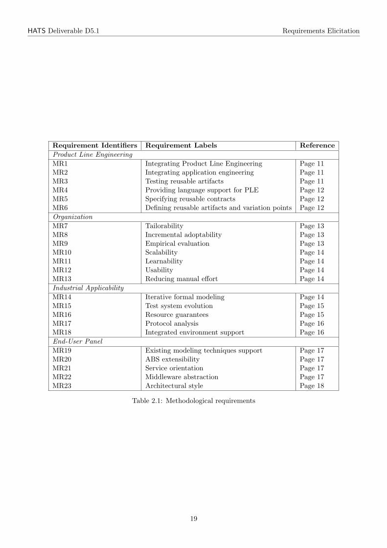
Each requirement harvested in Chapter 2 has a label consisting of a unique identifier prefixed with MR,as well as a descriptive name. Table 2.1 at the end of Chapter 2 shows an overview of the methodologicalrequirements.
Case studies
Scenarios and concerns in the case studies chapters are also uniquely identified. For the trading system casestudy in Chapter 3, each scenario has a unique identifier prefixed by TS and a descriptive name, while eachconcern has a unique identifier prefixed by TS-C and also a descriptive name. Table 3.1 shows an overviewof the scenarios and concerns considered in this case study, while Table 3.2 maps each HATS project’s worktask to the concerns that the task could help to address. Both tables can be found at the end of Chapter 3.
For the Virtual Office of the Future case study in Chapter 4, each scenario has a unique identifierprefixed by VF and a descriptive name, while each concern has a unique identifier prefixed by VF-C andalso a descriptive name. Table 4.1 shows an overview of the scenarios and concerns considered in this casestudy, while Table 4.2 maps each HATS project’s work task to the concerns that the task could help toaddress. Both tables can be found at the end of Chapter 4.
For the Fredhopper product case study in Chapter 5, each scenario has a unique identifier prefixedby FP and a descriptive name, while each concern has a unique identifier prefixed by FP-C and also adescriptive name. Table 5.1 shows an overview of the scenarios and concerns considered in this case study,while Table 5.2 maps each HATS project’s work task to the concerns that the task could help to address.Both tables can be found at the end of Chapter 5.
We have included Table 1.2.4 which maps task numbers to their task names.
1.2.4 Scope and structure
This deliverable defines high level requirements and concerns that the HATS framework should satisfy. Herewe consider the scope of the deliverable in terms of the methodological requirements and the concernsidentified through case studies. We stress that some methodological requirements and technical concernsidentified through case studies might not be achievable within a basic research project such as HATS. Anachievable scope for the validation process will be identified in Task 5.2 and become part of deliverable D5.2.
Moreover, in Task 5.2 we will carry out extensive analysis on the high level requirements and concerns.The result will give a structured classification to the analyzed requirements. The requirement analysis inTask 5.2 will also refine the requirements and concerns identified in this deliverable. This will minimizeambiguity and maximize verifiability of the requirements and concerns throughout the validation process inWP5.
Remark: Deliverable D5.1 is not meant to prescribe a comprehensive set of requirements for the technicalwork packages 1–4. It provides initial input and needs to be complemented by requirements and concernsprovided by the work package teams themselves. Although this is not the standard approach to elicit require-ments in a commercial software project, it is appropriate and from our point of view even necessary in abasic research project to bootstrap development of a method extending the state of the art. The work packageand task leaders are leading experts in their respective fields that will provide additional requirements in theHATS method as well as the ABS language as soon as they know the case studies and scenarios introduced inTask 5.1. The work of the work packages in HATS as a basic research project should not be over-constrained.The requirements provided in D5.1 will be extended and detailed in T5.2 in close collaboration with all taskleaders based on D5.1.
8
HATS Deliverable D5.1 Requirements Elicitation
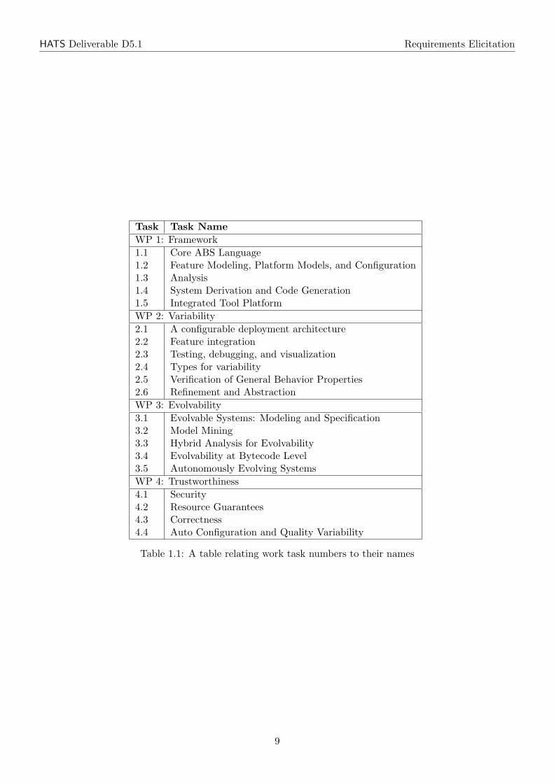
Task Task NameWP 1: Framework1.1 Core ABS Language1.2 Feature Modeling, Platform Models, and Configuration1.3 Analysis1.4 System Derivation and Code Generation1.5 Integrated Tool PlatformWP 2: Variability2.1 A configurable deployment architecture2.2 Feature integration2.3 Testing, debugging, and visualization2.4 Types for variability2.5 Verification of General Behavior Properties2.6 Refinement and AbstractionWP 3: Evolvability3.1 Evolvable Systems: Modeling and Specification3.2 Model Mining3.3 Hybrid Analysis for Evolvability3.4 Evolvability at Bytecode Level3.5 Autonomously Evolving SystemsWP 4: Trustworthiness4.1 Security4.2 Resource Guarantees4.3 Correctness4.4 Auto Configuration and Quality Variability
Table 1.1: A table relating work task numbers to their names
9
Chapter 2
Methodological Requirements
This chapter collects general requirements on the HATS methodology. Thereby, we distinguish differentperspectives. As product line engineering (PLE) provides the methodological basis of HATS we identifyrequirements from the point of view of a PLE researcher. Furthermore, requirements from an industrialperspective are presented. Fraunhofer IESE as an applied research organization focusing on technologytransfer provides general requirements in the HATS methodology to be able to introduce the HATS resultsin industry during, but mainly after, the project. Fredhopper as the industrial partner in the HATS projectprovides requirements from their perspective. Finally, we present requirements from members of the HATSend-user panel elicited in telephone interviews. Some of the requirements described in this chapter willautomatically be fulfilled if the project is conducted according to its proposal, for instance, the need for em-pirical evaluation of the HATS methodology is already manifested in work package five (WP5) on validation.Others, like the tailorability of the HATS method to different organizational contexts, are not yet explicitlymentioned in the proposal. Several requirements in this chapter, especially the ones presented in the sectionon the Fraunhofer perspective (Section 2.2) are very ambitious to be fulfilled in a basic research project likeHATS. Consequently, their complete fulfillment is not in the scope of the HATS project. Nevertheless, welist them here as researchers of the HATS project should always keep them in mind to increase the likelihoodthat the HATS results can be transferred to industry after the project has been finished.
2.1 Product line engineering
This section provides general requirements from the product line engineering perspective. Thereby, we covertopics like the overall product-line life cycle, application engineering, architecture, regression testing, andevolution in general. We selected such topics based on our experience in Product Line Engineering.
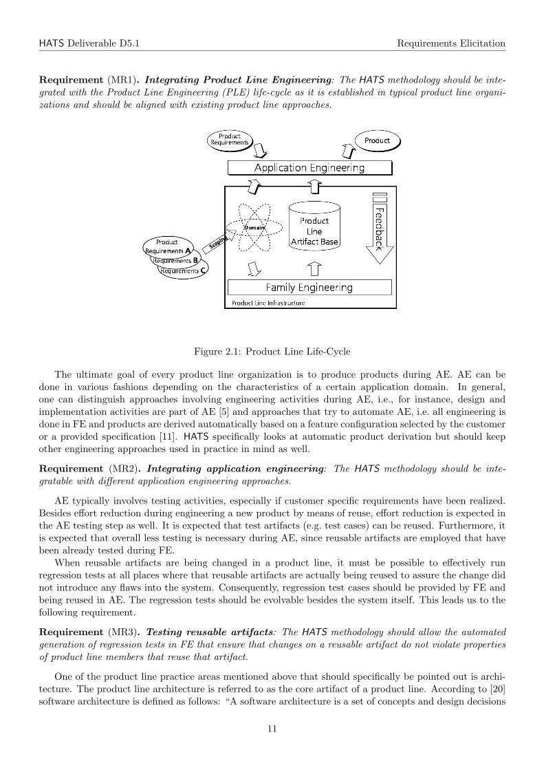
Product line engineering (PLE) splits the overall development life-cycle into application engineering(AE) and family engineering (FE) (see Figure 2.1) [24]. FE builds reusable artifacts that are stored in aproduct line artifact base. Thereby, scoping provides the requirements to be fulfilled by FE. The product lineartifacts provided by FE are generic, i.e. they contain variation points. AE builds products based on reusefrom the product line artifact base. Variation points in reusable artifacts are resolved and product specificextensions are made to come up with the final customer specific products. Product line engineering methodsin the end need to contribute to such essential activities in the product line life cycle. Either they supportFE, i.e. they need to be able to deal with generic artifacts containing variation points, or they address AE,i.e. they need to deal with reuse and reusable artifacts that need to be instantiated, evolved, tested etc. fora specific customer’s product. Product line methods like Fraunhofer PuLSE or the product line practiceframework of the Software Engineering Institute [9] list essential product line activities that need to beconducted in the context of the product line life cycle. The HATS methodology should be aligned with suchexisting comprehensive product line approaches. Hence, we can formulate the following requirement.
10
HATS Deliverable D5.1 Requirements Elicitation
Requirement (MR1). Integrating Product Line Engineering: The HATS methodology should be inte-grated with the Product Line Engineering (PLE) life-cycle as it is established in typical product line organi-zations and should be aligned with existing product line approaches.
Figure 2.1: Product Line Life-Cycle
The ultimate goal of every product line organization is to produce products during AE. AE can bedone in various fashions depending on the characteristics of a certain application domain. In general,one can distinguish approaches involving engineering activities during AE, i.e., for instance, design andimplementation activities are part of AE [5] and approaches that try to automate AE, i.e. all engineering isdone in FE and products are derived automatically based on a feature configuration selected by the customeror a provided specification [11]. HATS specifically looks at automatic product derivation but should keepother engineering approaches used in practice in mind as well.
Requirement (MR2). Integrating application engineering: The HATS methodology should be inte-gratable with different application engineering approaches.
AE typically involves testing activities, especially if customer specific requirements have been realized.Besides effort reduction during engineering a new product by means of reuse, effort reduction is expected inthe AE testing step as well. It is expected that test artifacts (e.g. test cases) can be reused. Furthermore, itis expected that overall less testing is necessary during AE, since reusable artifacts are employed that havebeen already tested during FE.
When reusable artifacts are being changed in a product line, it must be possible to effectively runregression tests at all places where that reusable artifacts are actually being reused to assure the change didnot introduce any flaws into the system. Consequently, regression test cases should be provided by FE andbeing reused in AE. The regression tests should be evolvable besides the system itself. This leads us to thefollowing requirement.
Requirement (MR3). Testing reusable artifacts: The HATS methodology should allow the automatedgeneration of regression tests in FE that ensure that changes on a reusable artifact do not violate propertiesof product line members that reuse that artifact.
One of the product line practice areas mentioned above that should specifically be pointed out is archi-tecture. The product line architecture is referred to as the core artifact of a product line. According to [20]software architecture is defined as follows: “A software architecture is a set of concepts and design decisions
11
HATS Deliverable D5.1 Requirements Elicitation
about the structure and texture of software that must be made prior to concurrent engineering to enableeffective satisfaction of architecturally significant explicit functional and quality requirements and implicitrequirements of the product family, the problem, and the solution domains.” A product line architectureis a generic artifact and defines the architecture for all the members of a product line. Compliance of aproduct architecture with the product line architecture facilitates high reuse rates of product line compo-nents. The product line architecture implies certain constraints to the product line components to be ableto realize system wide properties like performance, security, availability, etc. During component design theconstraints imposed by the architecture, for instance, regarding performance or how to realize security needto be considered. To be able to reason about the overall quality of the system on the architecture level,components should explicitly specify their quality properties, i.e. languages to specify components like theenvisioned ABS language should provide the possibility to express quality properties of components. Besidesthe possibility to reason about the overall system quality on an architecture level this enables to specifyevolution requirements. If in the context of an evolution a component is to be replaced, for instance, thespecification of the component’s quality properties can be used to select and evaluate the new component.Hence, we can formulate the following requirement.
Requirement (MR4). Providing language support for PLE: The HATS methodology should take therole of the product line architecture as the core artifact of a product line explicitly into account. Consequently,the ABS language, should provide language constructs to specify quality properties of components.
Product Line Engineering involves three types of artifacts: (a) reusable artifacts, (b) customized instancesof reusable artifacts and (c) product-specific artifacts. Reusable artifacts are the result of FE. The goal ofFE is to provide reusable artifacts that can be easily employed in the context of a product line member forsolving a concrete problem. Customized instances of reusable artifacts are the result of AE. In this case,already existing reusable artifacts are either reused as-is (i.e. without any modifications) or configured andthen adapted to the needs of a product line member. Finally product-specific artifacts are also the result ofAE. Those artifacts emerge in the context of a particular product line member without reusing any artifactsprovided by FE.
Product line evolution scenarios can hence be organized along the above three categories. A changerequest may either involve a reusable component, a customized instance or a product-specific component.The first two categories are of particular interest. When a reusable component evolves the change mightneed propagation to all customized instances that originate from it. On the other hand, when a customizedcomponent instance evolves, it should be easy to track that change so that reusable components the instancehas been derived from can be revised. The ABS language could support evolution explicitly as follows.
Requirement (MR5). Specifying reusable contracts: The ABS language should allow product line en-gineers to specify reuse contracts. A reuse contract describes how a component can be reused and specificallyhow it is actually being reused within a given product line member.
For facilitating software impact analysis it is necessary that constituent parts of a software system haveclearly specified interrelations. In the FE phase of Product Line Engineering reusable artifacts as, forinstance, components are developed. Those components are reusable by containing variation points thatcapture what may vary in the component and how it may vary. For enabling impact analysis on reusablecomponents it is necessary to have clear relations between the components but also between the variationpoints within the components.
Requirement (MR6). Defining reusable artifacts and variation points: The HATS methodologyshould allow defining reusable artifacts and variation points contained therein as well as the according in-terdependencies.
2.2 Organization: Fraunhofer IESE perspective
In this section the requirements from an organization perspective are elaborated in detail. As mentionedabove we distinguish between managers deciding on the adoption of the HATS methodology and users as well
12
HATS Deliverable D5.1 Requirements Elicitation
as Fredhopper as a member of the HATS consortium and members of the HATS end-user panel. Industrialorganizations are mainly interested into how the HATS methodology can be adopted in their specific contextand into the expected benefits. In the industrial context several stakeholders can be identified in the HATScontext: managers that have to decide on the adoption of the HATS method in their project or even theoverall organization and users or developers applying the HATS method in their daily work.
2.2.1 Managers’ perspective
This section covers the requirements in the HATS methodology from the point of view of a manager in anindustrial context. They have been derived by the authors of this deliverable and have been confirmed inthe interviews with members of the end-user panel.
Typically, organizations have established development processes that should be improved but not re-placed. Organizations want to keep development practices that have proven to work well in their contextand select new practices to solve existing issues. Let’s assume the following example: An organization al-ready uses component-oriented development, for instance, according to KobrA [4], and models componentsusing the Unified Modeling Language(UML). Developers have several years of experience with UML andUML models are successfully used for code generation. Introducing the HATS ABS Language and relatedcode generation techniques in this context requires their adaptation to the described context. The usage ofABS and the HATS code generation technique needs to be combined with UML modeling and UML basedcode generation. Otherwise the acceptance rate of the HATS approach in such an organization will be low.
Requirement (MR7). Tailorability: The HATS methodology must support its tailoring to a specific orga-nizational context. The HATS methodology needs to provide certain adjustment parameters that enable itstailoring to, for instance, the existing development practices in an organization, the application domain, thestructure of an organization, or the experience of the developers.
A complete introduction of the HATS methodology in an organization in a big-bang fashion leads tolarge-scale changes that may compromise the ongoing development activities. Furthermore, certain aspectsof the HATS methodology are not relevant in a specific organizational context. Hence, an incremental andpartial introduction of the HATS methodology needs to be possible which can be achieved by a modularstructure of the HATS methodology. Different adoption strategies should be sketched that illustrate in whichorder certain modules of the HATS methodology should be introduced depending on the current situationin an organization.
Requirement (MR8). Incremental adoptability: The HATS methodology must be designed modularlyto support its incremental introduction as well as partial adoption.
Managers demand a solid basis for decision making in their organization whether the HATS methodologyis appropriate or not. Case studies and controlled experiments should show the pros and cons of the adoptionof the overall HATS methodology but also of single modules of the HATS methodology that can be appliedin isolation.
Requirement (MR9). Empirical evaluation: The HATS methodology must be empirically evaluated todemonstrate that the expected benefits like higher quality in terms of trustworthiness, lower effort and costto achieve such quality, and less time required can be achieved. The benefits need to be quantified by meansof concrete measures and the context in which the empirical evaluation has been conducted needs to bethoroughly documented.
The HATS methodology aims at providing support for small, medium, and large systems and organiza-tions. In the case of large systems it should be applicable to system parts first and then be extended tocover the overall system. This requires the HATS methodology to be applicable to small systems or systemparts without causing significant overhead in terms of effort.
13
HATS Deliverable D5.1 Requirements Elicitation
Requirement (MR10). Scalability: The HATS methodology must be scalable, i.e. it needs to provide highquality results by using reasonable effort in the case of small, medium, and large scale systems. Applyingit to larger systems parts or systems with higher complexity should not cause more than linear increase ofeffort and constantly deliver high quality.
2.2.2 Users’ perspective
This section covers the requirements in the HATS methodology from the point of view of a user fromindustry, i.e. a developer, tester, architect, designer. The requirements have been derived by the authors ofthis deliverable and have been confirmed in the interviews with members of the end-user panel.
Requirement (MR11). Learnability: The HATS methodology must be easy to learn. The new concepts tobe applied by developers in an organization introducing the HATS methodology should be kept simple to beunderstandable by developers with average skills and experience. This implies offering of good documentation,tutorials, incremental examples.
Requirement (MR12). Usability: The HATS methodology must be easy to use. Developers with averageskills and experience should be able to apply the HATS methodology with reasonable effort. For example, thisimplies tools designed for ease of use.
Requirement (MR13). Reducing manual effort: The HATS methodology must reduce manual effort aswell as the error-proneness of manually defined code.
If such requirements are fulfilled, the HATS methodology will find broad acceptance by developers astheir satisfaction at work will be increased.
2.3 Industrial applicability: Fredhopper’s perspective
In this section we examine the most distinctive characteristics of the software production method of theFredhopper consortium member as a provider of a service-oriented server software product. We aim tocollect methodological requirements to the HATS framework, so that it can easily support the Fredhopperproduction method out of the box.
Fredhopper offers services targeted at improving catalog-based sales over the Internet by assisting usersto find relevant items quickly. The services consist of different functional blocks - searching of sale items, fastnavigation of categorized items, promotional items, integration with third party online advertising systems(such as Google ADs), user context-based search, alternatives suggestions, and so on. Each block addressesdifferent areas of the main mission – to help clients increase their sales over the Internet.
2.3.1 Developing an evolving product
Fredhopper develops and maintains its own server software. Fredhopper regularly enhances its productwith new features to constantly offer to its clients a competitive edge. Therefore, Fredhopper employs adevelopment cycle that includes large iterations that regularly produce quality versions of the product. Inthis way, the product provides more values to clients at each evolutionary step.
Requirement (MR14). Iterative formal modeling: The HATS framework plans to apply formal methodsfor enhancing software production in many aspects. In iterative development, we want to allow iterativeformal modeling as well. For example, if the framework employs code generation, we have to consider modelmining out of code too. This will allow the developer to integrate the changes in the code into the model.
Since most software companies produce their software using many informal methods to produce the codeof their products, these companies have to attest the quality of their products by doing extensive checkingon whether the software does what one designs it to do. One typical approach includes testing by a team
14
HATS Deliverable D5.1 Requirements Elicitation
of Quality Assurance (QA) engineers. The test plans typically contain test cases harvested from designspecifications, solving of previous bugs, user requirements, and so on. This kind of testing is expensive,especially with products that evolve. Each iteration over the product code base may introduce changesto it. Every change brings the risk of regression - functionality attested in a previous iteration, suddenlybecomes wrong or inaccessible.
Fredhopper maintains a test system as a satellite to the product code base. The test system consistsof automated testing facilities and tests cases to perform. The test system contains tests which if passedaltogether, attest the quality of the product version. The automated test system changes or grows as theproduct changes or grows with each product version. Naturally, Fredhopper uses the test system to quicklydetect regression due to changes in the code base. The test system does continuous integration to reruntests based on several events: weekly, nightly, and based on individual updates made to the code base.
Requirement (MR15). Test system evolution: The HATS framework has to support iterative updates ofthe test system. For example, if we have test generation, tests may change following a change of constraintsin the model that the framework generates. The tools in the HATS system have to update the test systemwith the new or changed tests. The updated test system would subsequently rerun the changed tests.
We point out that software development companies that contract one-time pieces of software, may notneed to invest in such an incremental system, as clients may not agree to pay the additional investment tocreate and maintain it. Still, in the case of a necessary change at a later point in time, the client will paythe increased cost of a complete retest, instead of the initial investment in a test system that captures andautomates the test of the previous iteration.
2.3.2 Server software
Fredhopper backs its service to its clients with server software that it deploys for them. This server softwareruns long time and has to meet the Service Level Agreement (SLA) with the client. The SLA includes,among others, functionality, data interoperability, support and performance guarantees. For example, theperformance guarantees include:
• Stable memory usage guarantee;
• Number of concurrent user requests guarantee;
• Statistical average response time guarantee;
• Up time guarantee.
In order to make sure Fredhopper maintains the SLA between versions of its product, Fredhopper’siterative development process includes a phase which measures and compares various aspects of performance.For example, for memory guarantees, one measures the memory footprint of changed modules over differentdata sets. Measuring CPU utilization under concurrent user stress shows the capacity of the current codebase to process concurrent requests. Measuring average response time on simulated user requests makessure that the current code base covers the response time guarantee.
Requirement (MR16). Resource guarantees: The HATS framework will address resource guarantees.In this context, it would prove useful if the framework tooling allows performance metrics to be brokendown using structural information from the models. This resembles ’code profiling’ which uses structuralinformation mined from the code to decompose the overall performance measuring down to smaller pieces,In this way developers may focus on improving the biggest contributors to delays. The same applies tomemory and concurrency bottlenecks (high lock contention, etc).
15
HATS Deliverable D5.1 Requirements Elicitation
2.3.3 Software as a service
Fredhopper offers its software services in two different manners:
• Software product;
• Software as a service.
As a software product, Fredhopper integrates its own product with the electronic commerce (typically aweb shop) software of the client by installing and integrating it in the client’s IT infrastructure. As a softwareservice, Fredhopper deploys a product instance in-house and leases to its clients a software service over theInternet according to some SLA. The SLA for software service includes extended guarantees compared tothe product SLA:
• Additional connection guarantees;
• Interface guarantees.
Since Fredhopper hosts the service explicitly for its client, connection guarantees refer to additionalrequirements for connection throughput between the client infrastructure and Fredhopper infrastructure.
Interface guarantees define the messaging formats and protocols that Fredhopper service has to adhereto so that the client can have continuous service. This requirement becomes important, because whenhosting, Fredhopper may update the server version transparently to allow clients to get improvements forperformance, bug fixing and new features. In order to make sure the client does not get any undesiredfunctional degradations, Fredhopper has to strictly adhere to the same protocol.
In contrast, a product hosted at a client requires to fix the product version. In this case, software updatesat a client happen explicitly and the client typically plans testing phases. For service-oriented deployment,Fredhopper benefits from supporting transparent updates with no-protocol-degradation guarantees.
Requirement (MR17). Protocol analysis: The HATS framework addresses verification and protocolchecking issues. From the methodological point of view, it would prove useful to provide an analytical toolthat Fredhopper can integrate in its service provisioning process. The tool can support the detection of anyprotocol violations. Violations may be originated from unanticipated regressions in the Fredhopper product orunanticipated client misuses of the protocol. Furthermore, if such a tool can operate as a runtime component,Fredhopper may provide a proper default handling of the issue automatically during runtime. Note that thepossibility for such errors comes from the informal process of producing the Fredhopper product. In addition,Fredhopper does not have control over the remote client, which may abuse the protocol due to own regressionsor incorrect implementations.
2.3.4 Integrated tools development environment
Fredhopper uses a modern development environment. Such an environment has the characteristic that itintegrates all necessary tools. The integrated development environment (IDE) manages all resources thatconstitute the coding representation of the final product. These include models, text sources, tests, andso on. The IDE also integrates all activities in a development process - modeling, writing code, testing,collaboration with other team members, and so on.
Requirement (MR18). Integrated environment support: The tools of the HATS framework have tosupport usage in an integrated environment. As such these tools have to have:
• Interoperable formats. HATS tools that we expect to use in a sequence, have to speak common formats.
• Common visual representation. HATS tools may have different cores, working with different for-malisms. Nevertheless they have to operate in the common visual and easy to use control environmentof the IDE.
16
HATS Deliverable D5.1 Requirements Elicitation
• Common resources. An IDE manages project resources by building a heterogeneous repository ofresources, which one may share among teams and team members. The tools have to take into accountversioning and collaborative work.
• Ability to work with large projects. HATS tools have to scale. This may even mean that individual toolsand formalisms may have to introduce partitioning of models and splitting and merging of models justfor the sake of utilizing work across the team.
2.4 End-user panel perspective
In this section we present the requirements that the end-user panel stated in interviews that we conductedwith their representatives.
Many organizations in practice already use model-based development approaches. They invested con-siderable effort in the past to construct models that they use in development. Using the HATS methodologyin the future including the use of the ABS language may not lead to a loss of such efforts, i.e. organizationswant to reuse their models in the context of the HATS methodology. This leads to the following requirement.
Requirement (MR19). Existing modeling techniques support: The HATS methodology must be ableto cope with existing models in organizations. To allow the reuse of models from languages typically used inpractice today, for instance, UML activity diagrams with Petri-net semantics, the HATS methodology shouldprovide model-transformations from those models into ABS models.
Note that to address this requirement is probably out of the scope of the research agenda of the HATSproject and should be pursued in follow-up activities. The requirement has also to be relativized to theexistence of a formal semantics of source models. While activity diagrams have a fairly clear semantics, inpractice many companies use ad-hoc profiles that have at best informal meaning.
Organizations that are customizing their products for specific customers often try to restrict the allowedchanges. They define extension points in their applications and prevent modifications of the core application.In doing so, they keep control over the evolution of the core application. One of the key benefits of such anapproach is that the core application can be evolved without interfering with customer specific extensions.
Requirement (MR20). ABS extensibility: The ABS language should provide the possibility to on theone hand specify extension points of an ABS model to be used, for instance, for customizing activities andon the other hand specify a core model that should only be evolved by developers of the application core.
Large information systems today are often based on service-orientation. Services support the alignmentof business and IT by providing a means to map business related services to IT services. Sometimes servicesare composed to higher-level services to better align with the workflows of certain customers.
Requirement (MR21). Service orientation: The HATS methodology, and in particular the ABS lan-guage, should be able to deal with service-orientation. Ideally, the ABS language provides constructs tospecify services and their properties. Additionally, the composition of services should be considered.
Another major characteristic of today’s information systems is that they are surrounded by lots ofmiddleware realized in different technologies. Often, the behavior of such middleware is not specified whichcan lead to unexpected reactions of the respective software.
Requirement (MR22). Middleware abstraction: The ABS language should be able to abstract fromconcrete middleware technologies and provide means to describe the expected behavior of middleware solu-tions.
The architectural style of a system determines the component types and connector types that are usedto model a concrete system according to that style. Component and connector types have specific propertiesthat need to be expressible by the language used to model components and connectors, in the case of HATSthe ABS language.
17
HATS Deliverable D5.1 Requirements Elicitation
Requirement (MR23). Architectural style: The ABS must be able to specify the properties imposed by aspecific architectural style that is used for a concrete system to be modeled. Ideally, the ABS language wouldprovide different variants according to the architectural style used in the architecture of a concrete systemand provide the possibility to easily define new variants of it to address specific architectural styles.
2.5 Summary
Table 2.1 summarises all methodological requirements for short reference. We have presented requirementsgrouped by the different sources. We have selected representative source that guarantee that HATS pro-duces an efficient and usable methodology for applying formal methods to software development. The fourcategories of requirements emphasize the following issues:
Product line engineering This category focuses on support for PLE with formal methods.
Organization This category focuses on adoption, integration of the HATS new method into an existinginfrastructure for software production, including large operations.
Industrial applicability This category focuses on modern professional product-based development thatincludes evolving products with some performance guarantees.
End-user panel This category focuses on modern trends in productivity and knowledge management suchas links to different existing modeling languages and architectural styles for using them, middlewaresupport, and service orientations. Requirements in this category were harvested by interviewing mem-bers of the end-user panel of the HATS project.
Requirements in the categories “product line engineering” and “industrial applicability” are more specificthan those in the categories “organization” and “end-user panel”. In particular we envisage the HATSmethodology will meet some of these requirements (e.g. MR1 and MR14) by design, while other requirements(e.g. MR3 and MR16) in these two categories will be met by delivering corresponding technical contributionsfrom respective work tasks.
For more general requirements in the categories “organization” and “end-user panel”, we will applyfurther scoping to them so that HATS could contribute within the project time frame and resources. Insome cases, for example, MR19 this could mean to defer addressing requirements in follow-up projects.Scoping will be carried out in Task 5.2. In addition, Task 5.2 will further analyze all requirements to clarifyand finalize the mapping of work from requirements to work tasks.
18
HATS Deliverable D5.1 Requirements Elicitation
Requirement Identifiers Requirement Labels ReferenceProduct Line EngineeringMR1 Integrating Product Line Engineering Page 11MR2 Integrating application engineering Page 11MR3 Testing reusable artifacts Page 11MR4 Providing language support for PLE Page 12MR5 Specifying reusable contracts Page 12MR6 Defining reusable artifacts and variation points Page 12OrganizationMR7 Tailorability Page 13MR8 Incremental adoptability Page 13MR9 Empirical evaluation Page 13MR10 Scalability Page 14MR11 Learnability Page 14MR12 Usability Page 14MR13 Reducing manual effort Page 14Industrial ApplicabilityMR14 Iterative formal modeling Page 14MR15 Test system evolution Page 15MR16 Resource guarantees Page 15MR17 Protocol analysis Page 16MR18 Integrated environment support Page 16End-User PanelMR19 Existing modeling techniques support Page 17MR20 ABS extensibility Page 17MR21 Service orientation Page 17MR22 Middleware abstraction Page 17MR23 Architectural style Page 18
Table 2.1: Methodological requirements
19
Chapter 3
Trading System Case Study
3.1 Overview
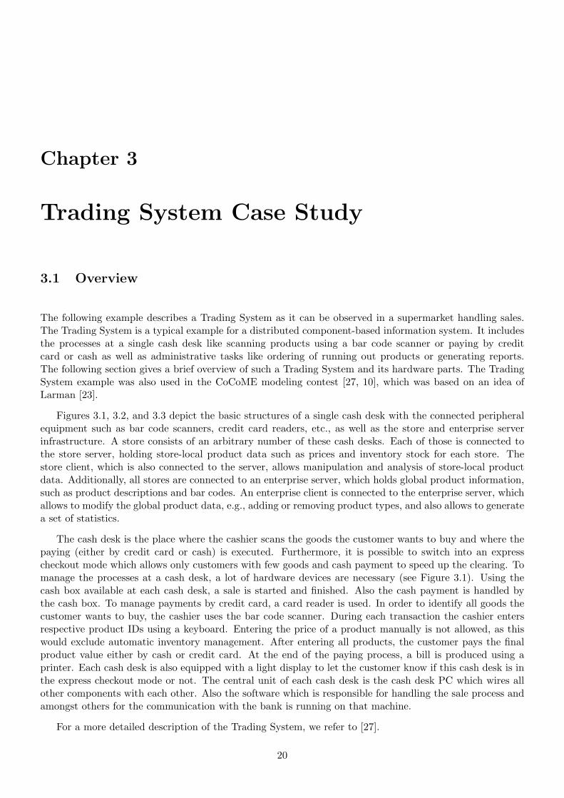
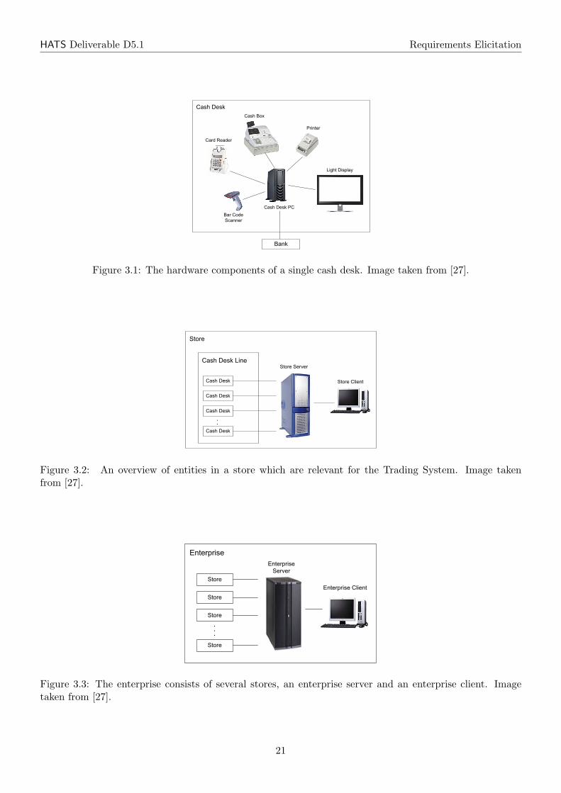
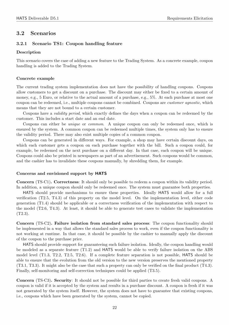
The following example describes a Trading System as it can be observed in a supermarket handling sales.The Trading System is a typical example for a distributed component-based information system. It includesthe processes at a single cash desk like scanning products using a bar code scanner or paying by creditcard or cash as well as administrative tasks like ordering of running out products or generating reports.The following section gives a brief overview of such a Trading System and its hardware parts. The TradingSystem example was also used in the CoCoME modeling contest [27, 10], which was based on an idea ofLarman [23].
Figures 3.1, 3.2, and 3.3 depict the basic structures of a single cash desk with the connected peripheralequipment such as bar code scanners, credit card readers, etc., as well as the store and enterprise serverinfrastructure. A store consists of an arbitrary number of these cash desks. Each of those is connected tothe store server, holding store-local product data such as prices and inventory stock for each store. Thestore client, which is also connected to the server, allows manipulation and analysis of store-local productdata. Additionally, all stores are connected to an enterprise server, which holds global product information,such as product descriptions and bar codes. An enterprise client is connected to the enterprise server, whichallows to modify the global product data, e.g., adding or removing product types, and also allows to generatea set of statistics.
The cash desk is the place where the cashier scans the goods the customer wants to buy and where thepaying (either by credit card or cash) is executed. Furthermore, it is possible to switch into an expresscheckout mode which allows only customers with few goods and cash payment to speed up the clearing. Tomanage the processes at a cash desk, a lot of hardware devices are necessary (see Figure 3.1). Using thecash box available at each cash desk, a sale is started and finished. Also the cash payment is handled bythe cash box. To manage payments by credit card, a card reader is used. In order to identify all goods thecustomer wants to buy, the cashier uses the bar code scanner. During each transaction the cashier entersrespective product IDs using a keyboard. Entering the price of a product manually is not allowed, as thiswould exclude automatic inventory management. After entering all products, the customer pays the finalproduct value either by cash or credit card. At the end of the paying process, a bill is produced using aprinter. Each cash desk is also equipped with a light display to let the customer know if this cash desk is inthe express checkout mode or not. The central unit of each cash desk is the cash desk PC which wires allother components with each other. Also the software which is responsible for handling the sale process andamongst others for the communication with the bank is running on that machine.
For a more detailed description of the Trading System, we refer to [27].
20
HATS Deliverable D5.1 Requirements Elicitation
!"#$%
&'()*+%(,*-./%
&'()*+%(,
&'()*0#1
&'$2*3%'2%$
4$./"%$
-.5)"*+.(67'8
0'$*%*
!9'//%$
&'()*+%(,*4&
&'()*+%(,
&'()*+%(,
&'()*+%(,
&'()*+%(,
!"#$%*!%$:%$
0'/,
!"#$%*&7.%/"
Fig. 1. The hardware components of a single Cash Desk.
!"#$%&'(
!")*%+,"*,)
-)./0,)
1.2$0%3.#45"6
&")%!'*,%
78"//,)
!"#$%3,#9%-!
!"#$%3,#9
!"#$%3,#9
!"#$%3,#9
!"#$%3,#9
70'),%7,):,)
70'),%!5.,/0
Fig. 2. An overview of entities in a store which are relevant for the Trading System.
!"#$%
!"#$%
!"#$%
!"#$%
&'"%$($)*%+
!%$,%$
&'"%$($)*%+-.)%'"
Fig. 3. The enterprise consists of several stores, an enterprise server and an enterpriseclient.
Figure 3.1: The hardware components of a single cash desk. Image taken from [27].
!"#$%
&'()*+%(,*-./%
&'()*+%(,
&'()*0#1
&'$2*3%'2%$
4$./"%$
-.5)"*+.(67'8
0'$*%*
!9'//%$
&'()*+%(,*4&
&'()*+%(,
&'()*+%(,
&'()*+%(,
&'()*+%(,
!"#$%*!%$:%$
0'/,
!"#$%*&7.%/"
Fig. 1. The hardware components of a single Cash Desk.
!"#$%&'(
!")*%+,"*,)
-)./0,)
1.2$0%3.#45"6
&")%!'*,%
78"//,)
!"#$%3,#9%-!
!"#$%3,#9
!"#$%3,#9
!"#$%3,#9
!"#$%3,#9
70'),%7,):,)
70'),%!5.,/0
Fig. 2. An overview of entities in a store which are relevant for the Trading System.
!"#$%
!"#$%
!"#$%
!"#$%
&'"%$($)*%+
!%$,%$
&'"%$($)*%+-.)%'"
Fig. 3. The enterprise consists of several stores, an enterprise server and an enterpriseclient.
Figure 3.2: An overview of entities in a store which are relevant for the Trading System. Image takenfrom [27].
!"#$%
&'()*+%(,*-./%
&'()*+%(,
&'()*0#1
&'$2*3%'2%$
4$./"%$
-.5)"*+.(67'8
0'$*%*
!9'//%$
&'()*+%(,*4&
&'()*+%(,
&'()*+%(,
&'()*+%(,
&'()*+%(,
!"#$%*!%$:%$
0'/,
!"#$%*&7.%/"
Fig. 1. The hardware components of a single Cash Desk.
!"#$%&'(
!")*%+,"*,)
-)./0,)
1.2$0%3.#45"6
&")%!'*,%
78"//,)
!"#$%3,#9%-!
!"#$%3,#9
!"#$%3,#9
!"#$%3,#9
!"#$%3,#9
70'),%7,):,)
70'),%!5.,/0
Fig. 2. An overview of entities in a store which are relevant for the Trading System.
!"#$%
!"#$%
!"#$%
!"#$%
&'"%$($)*%+
!%$,%$
&'"%$($)*%+-.)%'"
Fig. 3. The enterprise consists of several stores, an enterprise server and an enterpriseclient.
Figure 3.3: The enterprise consists of several stores, an enterprise server and an enterprise client. Imagetaken from [27].
21
HATS Deliverable D5.1 Requirements Elicitation
3.2 Scenarios
3.2.1 Scenario TS1: Coupon handling feature
Description
This scenario covers the case of adding a new feature to the Trading System. As a concrete example, couponhandling is added to the Trading System.
Concrete example
The current trading system implementation does not have the possibility of handling coupons. Couponsallow customers to get a discount on a purchase. The discount may either be fixed to a certain amount ofmoney, e.g., 5 Euro, or relative to the actual amount of a purchase, e.g., 5%. At each purchase at most onecoupon can be redeemed, i.e., multiple coupons cannot be combined. Coupons are customer agnostic, whichmeans that they are not bound to a certain customer.
Coupons have a validity period, which exactly defines the days when a coupon can be redeemed by thecustomer. This includes a start date and an end date.
Coupons can either be unique or common. A unique coupon can only be redeemed once, which isensured by the system. A common coupon can be redeemed multiple times, the system only has to ensurethe validity period. There may also exist multiple copies of a common coupon.
Coupons can be generated in different ways. For example, a shop may have certain discount days, onwhich each customer gets a coupon on each purchase together with the bill. Such a coupon could, forexample, be redeemed on the next purchase on a different day. In that case, each coupon will be unique.Coupons could also be printed in newspapers as part of an advertisement. Such coupons would be common,and the cashier has to invalidate these coupons manually, by shredding them, for example.
Concerns and envisioned support by HATS
Concern (TS-C1). Correctness: It should only be possible to redeem a coupon within its validity period.In addition, a unique coupon should only be redeemed once. The system must guarantee both properties.
HATS should provide mechanisms to ensure these properties. Ideally HATS would allow for a fullverification (T2.5, T4.3) of this property on the model level. On the implementation level, either codegeneration (T1.4) should be applicable or a correctness verification of the implementation with respect tothe model (T2.6, T4.3). At least, it should be able to generate test cases to validate the implementation(T2.3).
Concern (TS-C2). Failure isolation from standard sales process: The coupon functionality shouldbe implemented in a way that allows the standard sales process to work, even if the coupon functionality isnot working at runtime. In that case, it should be possible by the cashier to manually apply the discountof the coupon to the purchase price.
HATS should provide support for guaranteeing such failure isolation. Ideally, the coupon handling wouldbe modeled as a separate feature (T1.2) and HATS would be able to verify failure isolation on the ABSmodel level (T1.3, T2.2, T2.5, T2.6). If a complete feature separation is not possible, HATS should beable to ensure that the evolution from the old version to the new version preserves the mentioned property(T3.1, T3.3). It might also be the case that such a property can only be verified on the final product (T4.3).Finally, self-monitoring and self-correction techniques could be applied (T3.5).
Concern (TS-C3). Security: It should not be possible for third parties to create fresh valid coupons. Acoupon is valid if it is accepted by the system and results in a purchase discount. A coupon is fresh if it wasnot generated by the system itself. However, the system does not have to guarantee that existing coupons,i.e., coupons which have been generated by the system, cannot be copied.
22
HATS Deliverable D5.1 Requirements Elicitation
HATS should provide support for ensuring these security properties. Most likely, many techniques mustbe applied, ranging from the correctness verification of the component, which validates coupons (as describedabove), to guaranteeing confidentially and privacy policies (T4.1).
Concern (TS-C4). Resource: The system response time may not be noticeably slowed down during thesales process by the additional coupon functionality.
HATS could help here by allowing the specification of such resource properties on the model level andensuring this property on the implementation level (T4.2).
Concern (TS-C5). System upgrade: Existing cash desks need to be easily upgraded by the new softwarefunctionality. Ideally this would be done at runtime, while the cash desks are running.
HATS should allow to guarantee the safeness of such upgrades, ideally at runtime (T3.1, T3.3, T3.4).
3.2.2 Scenario TS2: Cash desk variability
Description
The trading system was originally designed as one possible configuration of a product line. As there is anincreasing demand by shop managers to tailor the shop application to specific needs, we want to set up oursystem as a product line to realize several shop scenarios.
Concrete example
A cash desk system should always allow a cashier to perform payment transactions. There are, however,multiple ways to realize this. The payment options which can be available are cash, credit card, prepaidcard, or electronic cash system like Maestro. Depending on the payment options, there is a need for severaladditional devices which allow to do credit card transactions. There can also be multiple ways for a cashierto enter bought goods into the system. For example, a barcode scanner, an RFID scanner or a keyboardcan be provided which allows the cashier to enter the respective product number. Some cash desks mayfurthermore provide a scale to weigh goods whose prices are not calculated on a per piece basis. Shopmanagers want to select payment options which are available to their clients and only need the requireddevices to realize these payment options. The same applies for input options to the cash desk system.
Concerns and envisioned support by HATS
Concern (TS-C6). Variability modeling: The HATS approach should provide support for modelingthe variability at the language level (T1.1, T1.2). An adaption of the ABS model to incorporate featuremodeling, different platform models and configurations should enable modular description of the presentedscenario using the HATS modeling approach (T1.2). It should furthermore be possible to generate differentconfigurations of the cash desks (T1.4).
Concern (TS-C7). Correctness: The HATS approach should guarantee that all possible product config-urations are correct for some definition of correctness, e.g., can be compiled, or satisfy certain invariants(T1.5). Also, a description of valid configurations should be possible (T2.1). To support these configura-tions, there is also a need for tools which allow for a simple deployment process of different configurations(T2.2). Visualization of variants, test generation and debugging for single features (T2.3) and their relationsis also of great importance. This can furthermore be supported by type systems and specification aspectswhich consider variability (T2.4).
3.2.3 Scenario TS3: Dependability property
Description
This scenario covers the case of formulating and verifying dependability properties [19]. As a concreteexample, one of the most important properties of a sale system, exact payment, is analyzed.
23
HATS Deliverable D5.1 Requirements Elicitation
Concrete example: Exact payment
For the customer of a shop, it is essential that he or she pays not more than the amount of the completepurchase costs. It is acceptable for a customer to pay less, though. From the shop owners’ perspective, acustomer should pay at least the price that a purchase costs, but may also be interested in not displeasing acustomer by charging too much. So, essentially, a shop owner is interested that a customer pays exactly theamount of money that the purchase costs. When the customer pays by cash, the system cannot guaranteemuch, because it is in the responsibility of the cashier to correctly count the money. However, when thecustomer pays by an electronic payment system, e.g., a credit card, the system should guarantee that thecorrect amount of money is withdrawn from the corresponding account. Two properties must be ensuredby the system, namely that the purchase price is calculated correctly, i.e., it must exactly reflect the sum ofall bought products, and that the calculated price is correctly withdrawn from the electronic account. Hereagain, the system must rely on the cashier to correctly scan all products.
Concerns and envisioned support by HATS
Concern (TS-C8). Correct price calculation: The component that calculates the price of a purchasemust do this correctly.
HATS should provide mechanisms to verify the correctness of the price calculation on the model level(T2.5, T4.3). On the implementation level, correctness should be ensured by either generating correct codefrom the model (T1.4), showing implementation correctness with respect to the model (T2.6), or at leastby generating test cases (T2.3).
Concern (TS-C9). Transactional behavior: The electronic payment process must be done in a transac-tional way, i.e., it should either completely be done or not at all. In the latter case, the payment processmust either be retried (for a fixed number of times) or fall back to cash payment. The system may only finishthe payment process if the correct amount of money was either been withdrawn from an electronic accountor paid by cash. If the customer has not enough cash to pay the purchase and the electronic payment didnot work, the payment process has to be canceled by the cashier. The system must also guarantee that anelectronic account is only charged once, or not at all, but never more than once for a single purchase.
HATS should provide mechanisms to guarantee the transactional behavior of the overall payment process.This property should be verifiable on the model level (T2.5, T4.3). Correctness on the implementation levelshould either be guaranteed (T1.4, T2.6) or at least, test cases should be generated, which cover the possiblefailure cases (T2.3).
Concern (TS-C10). Secure transactions: It should not be possible by third parties to interfere with thepayment process.
HATS could provide mechanisms to ensure this (T4.1).
3.2.4 Scenario TS4: Authentication policies
Description
So far, we have not considered security aspects in our shop application. To introduce the application into areal-life scenario, we have to take authentication and security mechanisms into account.
Concrete example
We want to distinguish between a set of roles in our application model. First of all, we have customers,cashiers and shop managers. Then, there are system administrators and enterprise management staff. Shopmanagers should only be allowed to access inventory information for their own shop and the distributioncenter. Cashiers should not be able to directly modify the inventory (only by selling goods). Neither shopmanagers nor cashiers should be able to access the credit card information of customers.
24
HATS Deliverable D5.1 Requirements Elicitation
Concerns and envisioned support by HATS
Concern (TS-C11). Security modeling and analysis: HATS should support modeling of authenticationand security features in the ABS language. Furthermore, analysis and verification of security policies atthe model and at the implementation level should be possible (T1.3, T2.5, T4.1, T4.3). Another importantproperty would be to show that the security model is implemented in a correct way. The HATS approachshould also provide the possibility to model security aspects on top of existing system specifications in amodular way.
3.2.5 Scenario TS5: Feature evolution - Loyalty system
Description
This scenario covers the case of a feature evolution. As a concrete example, the coupon handling feature ofScenario TS1 is extended to a full loyalty system.
Concrete example
The coupon handling feature described in Scenario TS1 only allows anonymous coupons to get a discount.To create an even stronger binding of a customer to a certain company or shop, loyalty programs can beused. In a loyalty program, customers can have a special loyalty card, which they can use for each purchase.Customers can then get discounts, which can be based on their individual shopping behavior. For example,it is possible to give a customer a discount of 10 Euros for every 100 Euros the customer spent when usinghis or her loyalty card. This total amount can be based on the sum of recent purchases of the customer andis not restricted to one single purchase.
Detailed description In order to implement the loyalty program, individual customers must be managedby the system. To participate in the loyalty program a customer has to fill out a form with his or her nameand address. Each new customer gets a unique customer id. The customer is then given out a loyalty card.In general, the customer will have to sign the card, and must agree that his or her private information andshopping behavior can be stored in the system and can be used for calculating the discount.
A loyalty card is a plastic card with a unique card id and a corresponding barcode1, which allows foran automatic scanning of the card id. The card id is also printed on the plastic card to allow for a manualinput by the cashier. It is possible to have multiple loyalty cards assigned to the same customer, e.g., toallow partner cards.
Whenever the customer does a purchase, he or she is asked for the loyalty card, which is then scannedby the system. After the payment of the purchase has finished, the corresponding information is stored inthe system. In a first simplified version, only the amount of the purchase may be stored, while in a moreadvanced system, the complete product list of the purchase could be stored.
The discount, which is provided to the customer, can be given in various different ways. For example,there could be a fixed discount of 1% for every purchase, which is directly applied to the current purchase.Another possibility is to print out an individual coupon for the customer, which he or she can redeem on thenext purchase. The individual coupon is bound to the customer and can only be redeemed together witha corresponding loyalty card. Such individual coupons can also be sent by mail to the customer’s address,either if the customer reached a certain purchase amount, or as part of an advertisement. Like the othercoupons described above, these coupons also have a validity period.
Concerns and envisioned support by HATS
All concerns, which are already mentioned in the coupon handling scenario, also apply to this scenario, sothese concerns are not repeated here. Only those concerns which are new to this scenario are mentioned
1Other technologies like magnetic strips, smart cards, or RFID chips are left out for simplicity.
25
HATS Deliverable D5.1 Requirements Elicitation
here.
Concern (TS-C12). Feature evolution: The most important aspect of this scenario is that of a featureevolution. The existing coupon handling feature is extended by individual coupons, which are bound to a cer-tain customer. This additional functionality should not influence the existing coupon handling functionalityfor anonymous coupons.
HATS should be able to model this new functionality. Ideally, it could be possible to completely factorout the additional functionality in a separate feature, which is based on the coupon handling feature andallow for different product configurations (T1.2, T2.2). It should then be possible to verify that the existingcoupon handling functionality is not affected by the loyalty extension. In particular, proofs done on theoriginal feature should be reusable (T3.1).
Concern (TS-C13). Privacy: One important aspect of the loyalty feature is to ensure that the privatepurchase information of the customer can only be used by the loyalty system to calculate the discount. Itis therefore important to save the customer information separately from product or inventory information.In addition, the system must guarantee that this information can only be used for the loyalty functional-ity. Certain authenticated staff members could also be allowed to access the information, building on theauthentication feature described in Scenario TS4.
HATS should provide mechanisms to ensure the isolation of the customer information, from unrelatedsystem functionality. Several different techniques have to be applied here, namely property verification onthe model level (T2.5, T4.3) and corresponding implementation correctness by code generation (T1.4) or byrefinement (T2.6), and enforcement of security requirements on the model level and on the implementationlevel, either by static analysis or by runtime checks (T4.1).
Concern (TS-C14). Security: As with the anonymous coupons, it should also not be possible to createnew valid individual coupons. In addition, it must not be possible for third-parties to modify the purchasesum of a customer in other ways except what has been described previously, i.e., by actually purchasingproducts.
HATS should provide similar mechanisms as described in Concern TS-C3.
Concern (TS-C15). Correctness: As with the other scenarios, HATS should allow to formally describe theproperties of this scenario and be able to verify them to a certain extend on the model and implementationlevel (T1.4, T2.3, T2.5, T2.6, T4.3).
3.3 Summary
The Trading System is an academic case study of moderate size. The focus of the scenarios lies on additionalfeatures and the variability of the system. Because of its size it should be possible to give a complete ABSmodel of the whole System. The model should be based on features, to be able to create different versionsof the system. Table 3.1 gives a summary of the concerns harvested from this case study and Table 3.2shows the relationship between concerns identified in this case study and tasks to be carried out in the HATSproject.
26
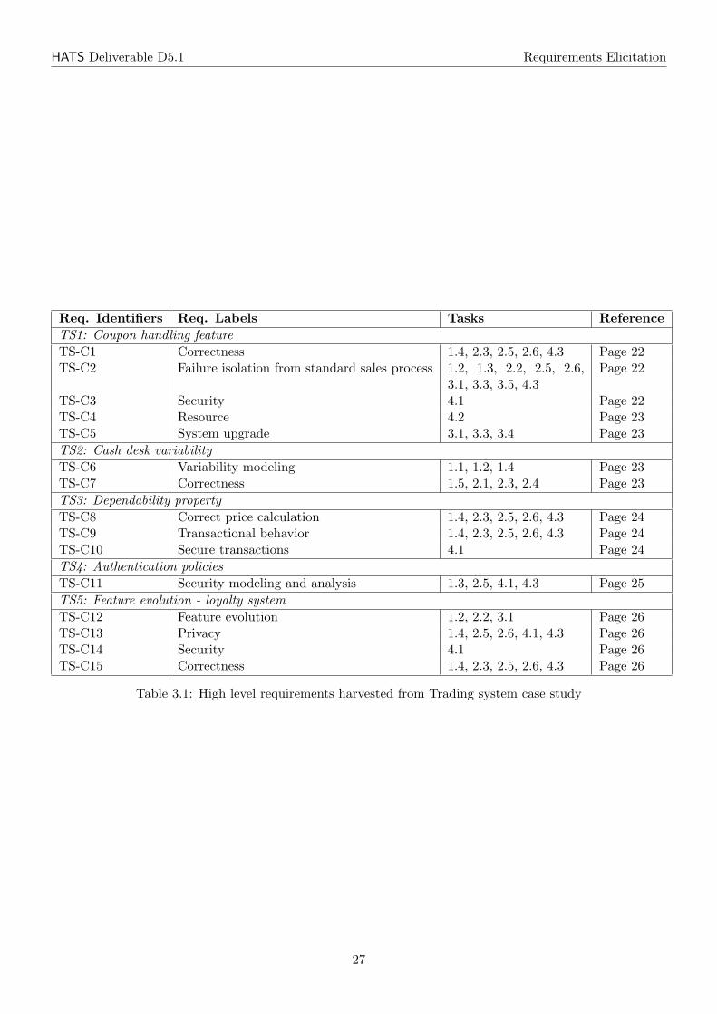
HATS Deliverable D5.1 Requirements Elicitation
Req. Identifiers Req. Labels Tasks ReferenceTS1: Coupon handling featureTS-C1 Correctness 1.4, 2.3, 2.5, 2.6, 4.3 Page 22TS-C2 Failure isolation from standard sales process 1.2, 1.3, 2.2, 2.5, 2.6,
3.1, 3.3, 3.5, 4.3Page 22
TS-C3 Security 4.1 Page 22TS-C4 Resource 4.2 Page 23TS-C5 System upgrade 3.1, 3.3, 3.4 Page 23TS2: Cash desk variabilityTS-C6 Variability modeling 1.1, 1.2, 1.4 Page 23TS-C7 Correctness 1.5, 2.1, 2.3, 2.4 Page 23TS3: Dependability propertyTS-C8 Correct price calculation 1.4, 2.3, 2.5, 2.6, 4.3 Page 24TS-C9 Transactional behavior 1.4, 2.3, 2.5, 2.6, 4.3 Page 24TS-C10 Secure transactions 4.1 Page 24TS4: Authentication policiesTS-C11 Security modeling and analysis 1.3, 2.5, 4.1, 4.3 Page 25TS5: Feature evolution - loyalty systemTS-C12 Feature evolution 1.2, 2.2, 3.1 Page 26TS-C13 Privacy 1.4, 2.5, 2.6, 4.1, 4.3 Page 26TS-C14 Security 4.1 Page 26TS-C15 Correctness 1.4, 2.3, 2.5, 2.6, 4.3 Page 26
Table 3.1: High level requirements harvested from Trading system case study
27
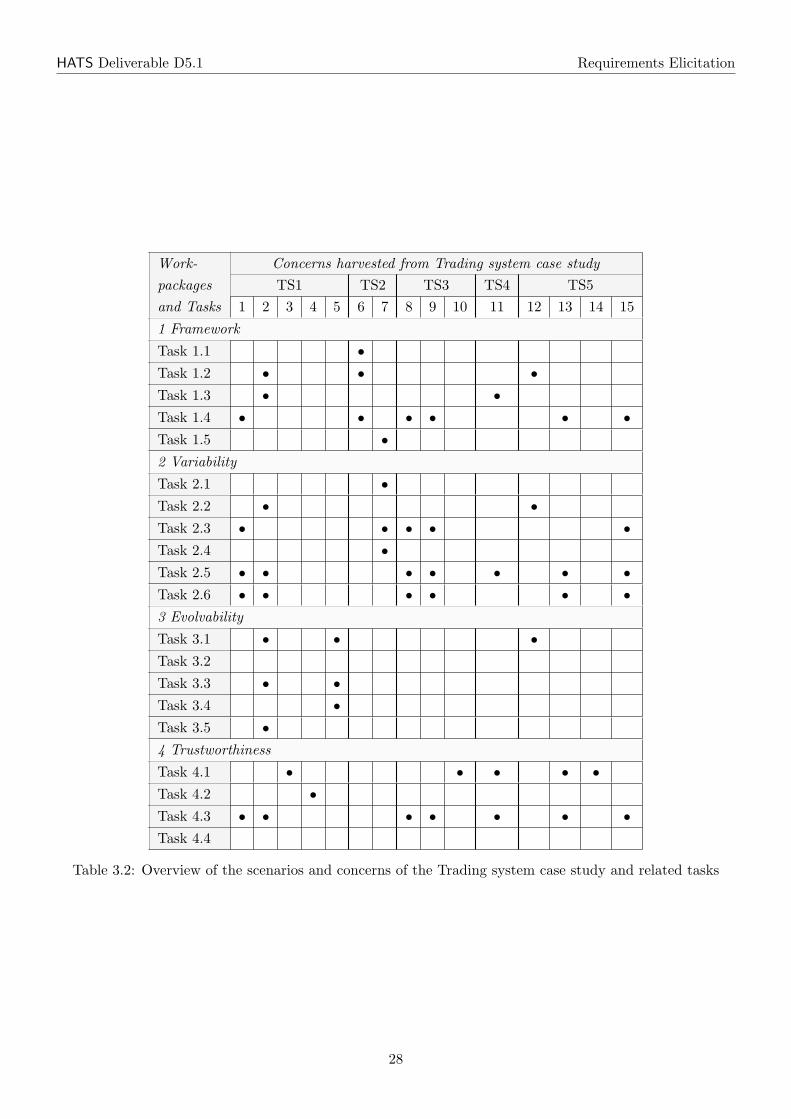
HATS Deliverable D5.1 Requirements Elicitation
Work- Concerns harvested from Trading system case studypackages TS1 TS2 TS3 TS4 TS5and Tasks 1 2 3 4 5 6 7 8 9 10 11 12 13 14 15
1 Framework
Task 1.1 •Task 1.2 • • •Task 1.3 • •Task 1.4 • • • • • •Task 1.5 •2 Variability
Task 2.1 •Task 2.2 • •Task 2.3 • • • • •Task 2.4 •Task 2.5 • • • • • • •Task 2.6 • • • • • •3 Evolvability
Task 3.1 • • •Task 3.2
Task 3.3 • •Task 3.4 •Task 3.5 •4 Trustworthiness
Task 4.1 • • • • •Task 4.2 •Task 4.3 • • • • • • •Task 4.4
Table 3.2: Overview of the scenarios and concerns of the Trading system case study and related tasks
28
Chapter 4
Virtual Office of the Future Case Study
4.1 Overview
In a Virtual Office of the Future (VOF), office workers are enabled to perform their office tasks seamlesslyindependent of their current location. They are supported by a highly distributed, decentralized officeinfrastructure that is made up by the devices that are accessible via network by an office worker at a givenpoint in time based on his current location. Office workers are able to use, for instance, devices like printersat their current location without knowing and installing them up-front or are able to securely exchangedocuments with colleagues in a meeting without using a central infrastructure. Fraunhofer IESE developeda prototype of an infrastructure aiming to support the vision of the VOF as sketched above. Following arethe main characteristics of the VOF infrastructure prototype:
Peer-to-peer (P2P) style The VOF infrastructure is a distributed system according to the P2P style.The nodes in the VOF P2P network are called VOF nodes. VOF nodes are devices like laptops, mobiledevices, printers, scanners, fax machines etc. that are connected to the VOF P2P network. The P2Pstyle enables the decentralization of the VOF infrastructure and thus facilitates mobile working.
Service-orientation VOF nodes provide their functionality in terms of services. Printers, for instance,provide print services describing the features they are capable of in a service description.
Virtualization Services related to concrete devices can be virtualized. The resulting VOF service providesfunctionality to office workers independent of a concrete device. A VOF print service, for instance,accepts print jobs and maps them to an appropriate device based on the user’s settings and contextinformation like the user’s current location. Hence, users do not need to deal with, for instance,specifics of single devices but are provided with higher-level VOF services.
Distributed workflow execution Workflows are executed in a distributed fashion. This is achieved bymeans of a concept called VOF documents. A VOF document is a document with attached workflow,data, and user interface. VOF documents are interpreted by VOF nodes, for instance, an office workerlaptop and thus executed. Local interpretation of VOF documents on office workers laptops enablesoffline working.
Integration with standard office applications Office workers typically use office applications like Mi-crosoft Office or Open Office. Hence, the VOF infrastructure is integrated with standard office appli-cations. Microsoft Outlook, for instance, has been integrated with the VOF infrastructure as a userinterface to enable its users to receive and send VOF documents.
The VOF infrastructure prototype is a framework that can be leveraged to realize support for officeworkflows on an underlying VOF P2P environment. A set of reusable artifacts is provided and a relatedproduction process describes how a VOF P2P environment can be set up and how new workflows can berealized and deployed on it.
29
HATS Deliverable D5.1 Requirements Elicitation
4.2 Reusable artifacts
According to the product line idea, the VOF infrastructure prototype comes up with a set of reusableartifacts and a production process that can be used to develop VOF infrastructures. The following reusableartifacts are available:
VOF P2P platform The VOF P2P platform is one of the core components of the VOF infrastructureprototype. It offers functionality to provide, discover, and execute VOF services in a P2P environment.Furthermore, it offers the ability to connect existing office applications of a customer like MicrosoftOutlook to the VOF infrastructure in order to use them as a UI. It is provided as a component that isready to use and can be installed on end devices that are planned to collaborate within a P2P network.
VOF documents A VOF document is an architectural concept developed by Fraunhofer IESE to realizeworkflows in a Virtual Office environment. In general, a VOF document is an entity consisting of aworkflow specification, files to be handled in a workflow, UIs to be used during the execution of aworkflow by a user, and data related to the execution of a workflow.
XML language to specify workflows This is a language developed by Fraunhofer IESE to describe theworkflows that are part of VOF Documents. Each workflow description contains the definition ofactivities, related roles, and data. It is based on XML and can be interpreted by a workflow enginethat is part of the VOF P2P platform.
Framework for VOF document user interfaces VOF Documents contain user interfaces used duringworkflow execution by the respective user. The framework for VOF document user interfaces consistsof libraries, APIs, and tools, and supports developers during the implementation of user interfaces inform of wizards and wizard pages.
Plug-in for MS Outlook This plug-in enables MS Outlook to be used in the context of a VOF infrastruc-ture. MS Outlook is extended to participate in workflows that are executed on the underlying VOFP2P platform. VOF documents realizing workflows can be received, edited, and sent via MS Outlook.
VOF services A VOF Service provides functionality to be used in a Virtual Office environment. Eachservice can be deployed on the VOF P2P platforms to make it available and executable. The VOFservices are used during the execution of workflows.
VOF service API This API is implemented in Java and has to be used to implement new VOF Servicesto become compliant with the general service specification used in the VOF P2P platform.
4.3 Scenarios
In this following section we describe concrete scenarios related to the VOF infrastructure prototype asevaluation candidates in the HATS project. The set of scenarios is not meant to be complete. It is thestarting point for discussion on the VOF infrastructure prototype in the context of the work packages.During the HATS project, further scenarios should be elaborated depending on the needs implied by theongoing work in HATS. If necessary, the scenarios will be elaborated in more detail before using them in arespective case study or experiment.
4.3.1 Scenario VF1: Realize a new workflow
One key requirement in the Virtual Office is the workflow support for office workers. For that, it must beeasy to introduce new workflows into the system. Hence, FRG developed the VOF document concept, whichoffers the ability to realize new workflows by developing a new VOF document.
30
HATS Deliverable D5.1 Requirements Elicitation
Concrete example
The concrete example we use here is an organization that wants to support requests for vacation electroni-cally. For the realization of these examples, a VOF document has to be implemented by following the stepsbelow:
1. Modeling the workflow with VOF workflow language
For the vacation workflow, the activities are:
• Filling out the vacation request form;
• Approve or Not approve the request by the department head;
• Forward the document to the administration;
• Send the document back to the requester.
The roles are:
• Requester;
• Department head;
• Administration.
The data involved are, for example:
• Requester personal data;
• Time period for vacation;
• Contact in vacation period;
• Substitute for the requester during the vacation period;
• Name of the department head.
2. Implementation of user interfaces
For the vacation workflow, four user interfaces are required:
• Request form;
• Approval or disapproval form;
• Administration form;
• Summarize form.
3. Identify services
For the vacation workflow, two services are required:
• Retrieve the name of the requester’s department head;
• Check the remaining vacation days of the requester.
4. Compiling the VOF document
For the vacation workflow, there are basically two files to be compressed:
• The XML workflow file containing the workflow description and the data bindings;
• Four user interface e files (Dynamic-Link Libraries - DLL’s);
31
HATS Deliverable D5.1 Requirements Elicitation
5. Deployment of the VOF document
The VOF document is now available in the peer network by copying it in each node in a specific folderwhich is accessible to all the related services.
The services are addressed to specific nodes according to the preference of the network manager.
6. Testing
A system test is performed in order to find errors in any component of the VOF document and fixthem. Once fixed, the entire VOF document is recompiled.
Concerns and envisioned support by HATS
Concern (VF-C1). Testability: The functionality of the workflow has to be guaranteed by testing all thepossible paths (T2.5).
Concern (VF-C2). Availability of document-related services: When deploying the VOF document,it has to be guaranteed that its related services will be available in the network (T2.5).
Concern (VF-C3). Services security: Concerning security, one point to be considered is how to ensurethat a user has access only to the service that it is supposed to. Another security issue is that the newworkflow should not cause significant delay in the network, caused by an unsecured implementation of theVOF Document. For instance, the VOF Document splits up itself and sends several times to each memberof the VOF (T4.1 and T4.2).
Concern (VF-C4). Analysis: Models of workflows can reach high complexity with respect to the controlflow and the use data types. Hence, workflow and related data models are source of inconsistencies anddefects that could be prevented by analysis techniques applied to the respective models (T1.3).
Concern (VF-C5). Code generation for workflow realization: Today the realization of a new workflowis concerned with many manual development activities. Code realizing the behavior of a VOF documentcannot be generated so far (T1.4).
4.3.2 Scenario VF2: Add a new device type to the VOF infrastructure
Office workers use different devices during their daily work in the Virtual Office. The probability that anew device type that has not yet been used within the VOF infrastructure before is very high. A concreteexample could be the integration of an iPhone as a new device type in the environment.
Concrete example
A reference architecture describes the required software components for end devices. The identified enddevice type (iPhone) has to be analyzed with respect to the operating system, available programmingplatforms (Objective C, Java, etc) and all constraints related to those issues. For instance, memory andCPU restrictions and library restrictions for programming platforms.
For adding a new device on the network, the following steps are required:
1. Implementation of software components concerning the end device type, if there is no concrete imple-mentation available. During the development of each software component, module tests are performedfor checking the functionality of each module.
2. The new implemented software product has to be installed on the end device (iPhone). Afterwards,the device has to join the P2P infrastructure for performing a system test.
32
HATS Deliverable D5.1 Requirements Elicitation
Concerns and envisioned support by HATS
Concern (VF-C6). Portability: We have to generate and offer different platform applications for differentend devices (T1.2).
Concern (VF-C7). Device security: The overall system has to know if the new node is trustable or notin reference to the provided services and its behavior in the network (T4.1).
Concern (VF-C8). Hybrid analysis for evolvability: New devices are supposed to be integrated to aVOF infrastructure at runtime. This bears the risk that the integration in a partially unknown environmentleads to runtime errors (T3.3).
4.3.3 Scenario VF3: Realization of a new VOF service
The realization of a workflow for a certain organization can require new functionality to be provided by anew service.
Concrete example
One concrete example can be a service for the authentication of users in the P2P network. For this, thefollowing steps are required:
1. First of all, the specification of the service interface has to be done by documenting the methodsignature of the service. Concerning the example:
authenticate(user, password) : boolean
2. A concrete implementation of the specification related to existing technologies is required. For instancean authentication mechanism for LDAP- or database servers, etc.
3. Testing the new implementation of the VOF Service.
Concerns and envisioned support by HATS
Concern (VF-C9). Availability of services: The functionality of the VOF is based on service con-sumption. It is necessary therefore to guarantee that a high availability of each service (T2.4, T4.3 andT4.4).
Concern (VF-C10). Variability: Based a on a service specification, we should have a variability point tobe able to select the different implementations (T2.4).
Concern (VF-C11). Correctness: If the implementation of a service specification changes, the function-ality of the service has to be guaranteed (T4.3).
4.3.4 Scenario VF4: Integration of a new virtual office application
The VOF P2P platform is capable to communicate with local running applications and vice versa, byproviding corresponding interfaces. Based on this, each application can be adapted to connect and use theVOF P2P platform. The workflow support based on VOF documents is integrated into office applicationslike Microsoft Outlook.
Concrete example
As a concrete example, consider the integration of a Thunderbird client instead of Microsoft Outlook.
1. Analyze existing APIs and programming tools for extending the Thunderbird application.
2. Integrate a software component (proxy) in the Thunderbird client to encapsulate the communicationbetween the mail application and the VOF P2P platform.
33
HATS Deliverable D5.1 Requirements Elicitation
Concerns and envisioned support by HATS
Concern (VF-C12). Test case generation: Automatic generation of test cases in order to verify thefunctionality between the new application (Thunderbird) and the platform (T1.4).
Concern (VF-C13). Model mining: The integration of a new office application like Thunderbird bears therisk that because of incomplete information about the new applications’ realization the integration fails oris at least error-prone. Model-mining can provide additional information on an application to be integrated(T3.2).
4.3.5 Scenario VF5: Integration of new functionality in the VOF P2P platform
The architecture of the VOF Middleware consists of a combination of different architectural styles. Themost important one is the layered- and event-driven style to address maintainability and customizabilityrequirements. Thus, changing or integrating new functionality can be done easily. But the adaptation ofevent flows can cause a high effort during implementation and testing phases, because the collaborationbetween components via events is hard to understand.
Concrete example
In this example, we integrate a security component for encrypting and decrypting messages between peers.The new functionality is optional and can be configured during runtime. For this, the following steps arerequired:
1. Definition of component interfaces, events, and configurability of the new security component.
2. Identify and adapt affected components related to new event flows.
3. Implementation of a security component prescribed by requirements, architecture and design.
4. Integrate configuration functionality in the UI.
5. Definition and implementation of test cases related to the updated event flow.
6. Build a new release of the VOF Middleware and deliver it to all clients.
Concerns and envisioned support by HATS
Concern (VF-C14). Feature modeling: Interfaces should be defined for the new component, as well asthe related events to describe the behavior (T1.2).
Concern (VF-C15). Variability: Adapt variation points of existing components to guarantee seamlessintegration of the new security component (T2.4).
Concern (VF-C16). Verification of general behavior properties: In order to check the correctness ofthe updated event flow, a couple of test cases should be generated to guarantee the integration of it withthe overall system (T2.5).
4.3.6 Scenario VF6: Replacement of technologies
To achieve new upcoming requirements, for instance the improvement of communication performance orbecoming standard compliant, it makes sense to replace used technologies in the overall system.
34
HATS Deliverable D5.1 Requirements Elicitation
Concrete example
In this example we replace the proprietary implementation of VOF Services by introducing the web-servicestandard. For this, the following steps are required:
1. Change the communication protocol used between peers, to discover VOF Services. For instance, theunique identification for discovering services has to be changed. Today, a service can be identified by”peername::servicename”. Using web-services causes a change to: http://peername:port/servicename.
2. Implement and provide components for the realization of the required environment for web-services(HTTP-Server with web-service container, etc).
3. Adapt all VOF Service implementations to become technology compliant.
4. Generate and replace all proxy components that encapsulate the communication technology, which isused for service execution.
5. Build a new release of the VOF Middleware and deliver it to all clients.
6. Rebuild and deliver all service implementations.
Concerns and envisioned support by HATS
Concern (VF-C17). Code generation: To keep the compliance among the services in the network, itshould be specified with ABS how each service should behavior with the introduction of a new technology.It means that parts of the source code should be replaced by code generated using ABS specification (T4.3).
Concern (VF-C18). System derivation: Based on the new introduced communication technology, allthe proxy components should be replaced in order to achieve the compatibility among the VOF applicationsand the middleware (T1.4).
Concern (VF-C19). Configurable deployment architecture: Once a new version of the VOF middle-ware was built, it has to be guaranteed that the version of the VOF middleware was deployed for all thenodes to avoid incompatibilities (T2.1).
Note that Fraunhofer IESE aims at providing tool-support for the development activities required toperform each of the scenarios.
4.4 Summary
This chapter introduced the Virtual office of the future case study to be used as validation example in theHATS project. The case study is an example for a software product line in the information systems domain.We introduced the available reusable artifacts, for instance, the VOF P2P platform, VOF documents, orVOF services and in particular 6 scenarios that can be leveraged for the validation of HATS results. Thescenarios describe typical situations we have experienced in working with the Virtual Office prototype andits evolution over time. The case study provides input to WP1-WP4. Table 4.1 gives a summary of theconcerns harvested from this case study and Table 4.2 shows the relationship between concerns identified inthis case study and tasks to be carried out in the HATS project.
35
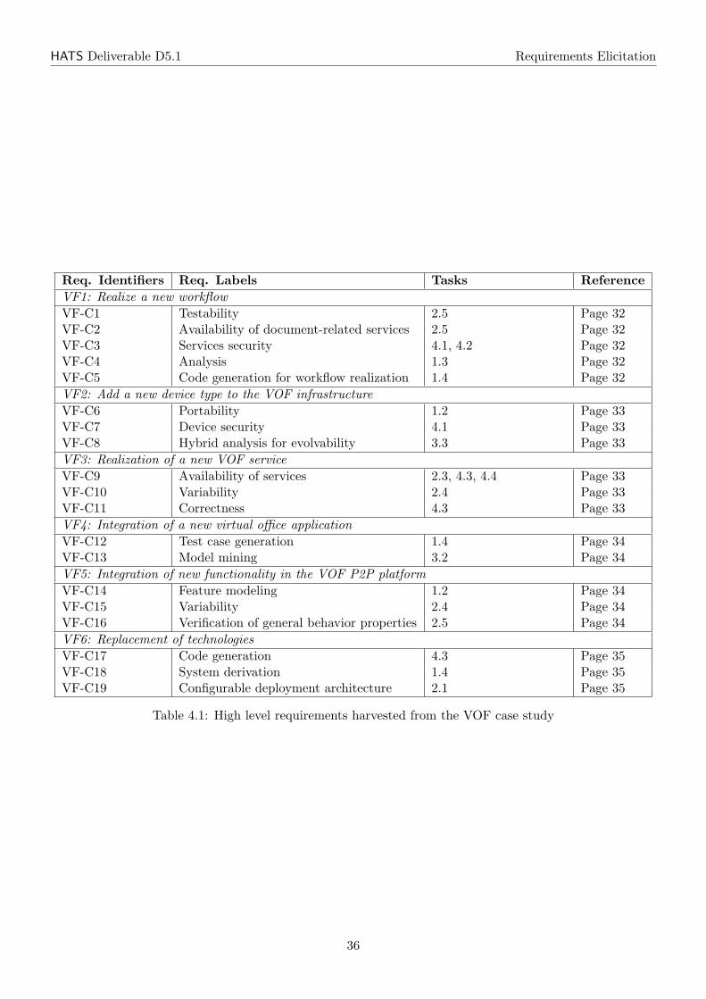
HATS Deliverable D5.1 Requirements Elicitation
Req. Identifiers Req. Labels Tasks ReferenceVF1: Realize a new workflowVF-C1 Testability 2.5 Page 32VF-C2 Availability of document-related services 2.5 Page 32VF-C3 Services security 4.1, 4.2 Page 32VF-C4 Analysis 1.3 Page 32VF-C5 Code generation for workflow realization 1.4 Page 32VF2: Add a new device type to the VOF infrastructureVF-C6 Portability 1.2 Page 33VF-C7 Device security 4.1 Page 33VF-C8 Hybrid analysis for evolvability 3.3 Page 33VF3: Realization of a new VOF serviceVF-C9 Availability of services 2.3, 4.3, 4.4 Page 33VF-C10 Variability 2.4 Page 33VF-C11 Correctness 4.3 Page 33VF4: Integration of a new virtual office applicationVF-C12 Test case generation 1.4 Page 34VF-C13 Model mining 3.2 Page 34VF5: Integration of new functionality in the VOF P2P platformVF-C14 Feature modeling 1.2 Page 34VF-C15 Variability 2.4 Page 34VF-C16 Verification of general behavior properties 2.5 Page 34VF6: Replacement of technologiesVF-C17 Code generation 4.3 Page 35VF-C18 System derivation 1.4 Page 35VF-C19 Configurable deployment architecture 2.1 Page 35
Table 4.1: High level requirements harvested from the VOF case study
36

HATS Deliverable D5.1 Requirements Elicitation
Work- Concerns harvested from VOF case studypackages VF1 VF2 VF3 VF4 VF5 VF6and Tasks 1 2 3 4 5 6 7 8 9 10 11 12 13 14 15 16 17 18 19
1 Framework
Task 1.1
Task 1.2 • •Task 1.3 •Task 1.4 • • •Task 1.5
2 Variability
Task 2.1 •Task 2.2
Task 2.3 •Task 2.4 • •Task 2.5 • • •Task 2.6
3 Evolvability
Task 3.1
Task 3.2 •Task 3.3 •Task 3.4
Task 3.5
4 Trustworthiness
Task 4.1 • •Task 4.2 •Task 4.3 • • •Task 4.4 •
Table 4.2: Overview of the scenarios and concerns of the VOF case study and related tasks
37
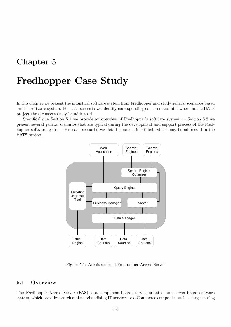
Chapter 5
Fredhopper Case Study
In this chapter we present the industrial software system from Fredhopper and study general scenarios basedon this software system. For each scenario we identify corresponding concerns and hint where in the HATSproject these concerns may be addressed.
Specifically in Section 5.1 we provide an overview of Fredhopper’s software system; in Section 5.2 wepresent several general scenarios that are typical during the development and support process of the Fred-hopper software system. For each scenario, we detail concerns identified, which may be addressed in theHATS project.
Query Engine
Data Manager
Business Manager Indexer
Search Engine Optimizer
Data Sources
Data Sources
Data Sources
Web Application
SearchEngines
Search Engines
TargetingDiagnostic
Tool
Rule Engine
Figure 5.1: Architecture of Fredhopper Access Server
5.1 Overview
The Fredhopper Access Server (FAS) is a component-based, service-oriented and server-based softwaresystem, which provides search and merchandising IT services to e-Commerce companies such as large catalog
38
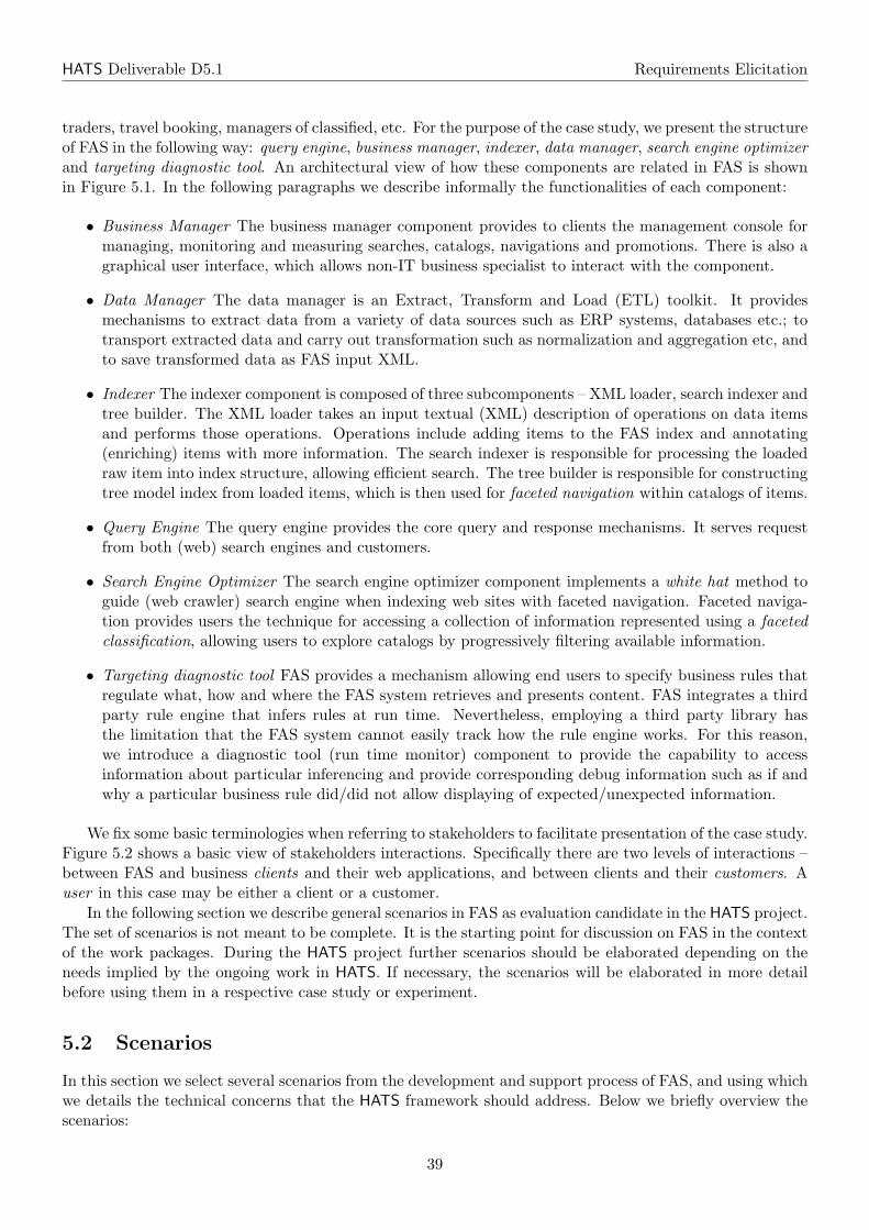
HATS Deliverable D5.1 Requirements Elicitation
traders, travel booking, managers of classified, etc. For the purpose of the case study, we present the structureof FAS in the following way: query engine, business manager, indexer, data manager, search engine optimizerand targeting diagnostic tool. An architectural view of how these components are related in FAS is shownin Figure 5.1. In the following paragraphs we describe informally the functionalities of each component:
• Business Manager The business manager component provides to clients the management console formanaging, monitoring and measuring searches, catalogs, navigations and promotions. There is also agraphical user interface, which allows non-IT business specialist to interact with the component.
• Data Manager The data manager is an Extract, Transform and Load (ETL) toolkit. It providesmechanisms to extract data from a variety of data sources such as ERP systems, databases etc.; totransport extracted data and carry out transformation such as normalization and aggregation etc, andto save transformed data as FAS input XML.
• Indexer The indexer component is composed of three subcomponents – XML loader, search indexer andtree builder. The XML loader takes an input textual (XML) description of operations on data itemsand performs those operations. Operations include adding items to the FAS index and annotating(enriching) items with more information. The search indexer is responsible for processing the loadedraw item into index structure, allowing efficient search. The tree builder is responsible for constructingtree model index from loaded items, which is then used for faceted navigation within catalogs of items.
• Query Engine The query engine provides the core query and response mechanisms. It serves requestfrom both (web) search engines and customers.
• Search Engine Optimizer The search engine optimizer component implements a white hat method toguide (web crawler) search engine when indexing web sites with faceted navigation. Faceted naviga-tion provides users the technique for accessing a collection of information represented using a facetedclassification, allowing users to explore catalogs by progressively filtering available information.
• Targeting diagnostic tool FAS provides a mechanism allowing end users to specify business rules thatregulate what, how and where the FAS system retrieves and presents content. FAS integrates a thirdparty rule engine that infers rules at run time. Nevertheless, employing a third party library hasthe limitation that the FAS system cannot easily track how the rule engine works. For this reason,we introduce a diagnostic tool (run time monitor) component to provide the capability to accessinformation about particular inferencing and provide corresponding debug information such as if andwhy a particular business rule did/did not allow displaying of expected/unexpected information.
We fix some basic terminologies when referring to stakeholders to facilitate presentation of the case study.Figure 5.2 shows a basic view of stakeholders interactions. Specifically there are two levels of interactions –between FAS and business clients and their web applications, and between clients and their customers. Auser in this case may be either a client or a customer.
In the following section we describe general scenarios in FAS as evaluation candidate in the HATS project.The set of scenarios is not meant to be complete. It is the starting point for discussion on FAS in the contextof the work packages. During the HATS project further scenarios should be elaborated depending on theneeds implied by the ongoing work in HATS. If necessary, the scenarios will be elaborated in more detailbefore using them in a respective case study or experiment.
5.2 Scenarios
In this section we select several scenarios from the development and support process of FAS, and using whichwe details the technical concerns that the HATS framework should address. Below we briefly overview thescenarios:
39
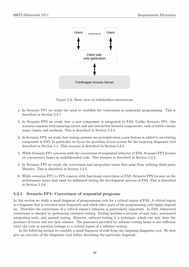
HATS Deliverable D5.1 Requirements Elicitation
Client side web application
Fredhopper Access Server
Users Users.........
Figure 5.2: Basic view of stakeholders interactions
1. In Scenario FP1 we study the need to establish the correctness in sequential programming. This isdescribed in Section 5.2.1.
2. In Scenario FP2 we study how a new component is integrated to FAS. Unlike Scenario FP1, thisscenario concerns with ensuring correct and safe interaction between components, each of which containmany classes and methods. This is described in Section 5.2.2.
3. In Scenario FP3, we study how testing systems are provided when a new feature is added to an existingcomponent in FAS. In particular we focus the provision of test system for the targeting diagnostic tooldescribed in Section 5.1. This scenario is described in Section 5.2.3.
4. While Scenario FP1 concerns with the correctness of sequential behavior of FAS, Scenario FP4 focuseson concurrency issues in multithreaded code. This scenario is described in Section 5.2.4.
5. In Scenario FP5 we study the correctness and integration issues that arise from utilizing third partylibraries. This is described in Section 5.2.5.
6. While scenarios FP1 to FP5 concern with functional correctness of FAS, Scenario FP6 focuses on theperformance issues that must be addressed during the development process of FAS. This is describedin Section 5.2.6.
5.2.1 Scenario FP1: Correctness of sequential programs
In this section we study a small fragment of programming code for a critical region of FAS. A critical regionis a fragment that is executed most frequently and which other parts of the programming code highly dependon. Therefore the correctness of a critical region’s behavior is particularly important. In FAS, behavioralcorrectness is checked by performing extensive testing. Testing includes a mixture of unit tests, automatedintegration tests, and manual testing. However, software testing is a technique, which can only show thepresence of errors and not their absence. The guarantee provided by software testing hence is not sufficientwhen the code in question belongs to a critical region of a software system.
In the following section we consider a small fragment of code from the targeting diagnostic tool. We firstgive an overview of the diagnostic tool before describing the particular fragment.
40
HATS Deliverable D5.1 Requirements Elicitation
1 public interface InferenceAnalyser {2 public void queryTrial(Object query);3 }
Listing 5.1: An excerpt of the public interface InferenceAnalyserIn FAS we use a business rule inferencing engine to define complete business configurations that regulate
how FAS performs queries and how FAS structures its response information. To implement the inferencingengine, we use a third party implementation of a rule engine, in order to reduce the cost of developing andmaintaining such a complex piece of technology ourselves. However the inferencing process carried out bythe rule engine can be complex. This mean it would be very difficult for business clients to know exactly howtheir business rules are evaluated. We therefore provide a targeting diagnostic tool to collect informationabout the business rules during the inferencing process. The tool has the goal to display this informationin a usable to the clients manner.
1 public class InferenceAnalyserImpl implements InferenceAnalyser {2 private RuleEngine ruleEngine = RuleEngines.createEngine();3 public void queryTrial(Object query) {4 ruleEngine.publish(query);5 for (Information stat : CollectorHolder.getCollector().getStats())6 ServletFactory.getPage().displayInformation(stat);7 }8 }
Listing 5.2: An excerpt of an implementation of the interface InferenceAnalyserDuring diagnosis, a business client submits a query input in the form of a URL to the diagnostic tool.
The tool then publishes input to a third party rule engine for inferencing. While the inferencing processis being carried out, the targeting diagnostic tool would collect information about each matching businessrule. This information includes the identification of the business rule as well as a break down of the partsof a business rule that are satisfied and parts that are not.
Listing 5.2 shows the code fragment to be considered in the following section. It is an excerpt of theclass InferenceAnalyserImpl, which is responsible for accepting the query input from the business client.To encapsulate our implementation we expose this feature via the InterfaceAnalyser. An excerpt of theinterface InterfaceAnalyser is shown in Listing 5.1. Specifically the method queryTrial() takes an URLand publishes it to the rule engine, which would carry out the inferencing procedure on this URL against aset of business rules. During the inferencing, a Collector object is responsible for storing information aboutevaluated business rules. The interface Collector is shown in Listing 5.3. After the inferencing, the methodqueryTrial() retrieves the information collected during the inferencing session and renders this informationon a web page to the business client. To retrieve the information collected during inferencing the methodqueryTrial() calls the static method CollectorHolder.getCollector() in line 5 from Listing 5.2.
1 public interface Collector {2 public List<Information> getStats();3 }
Listing 5.3: An excerpt of the public interface Collector
41
HATS Deliverable D5.1 Requirements Elicitation
Concrete example
In this section we use the code fragments introduced above to study the development and support process ofa critical section of a component in FAS. In particular we consider on the current method for guaranteeingthe correctness of the critical section in the following steps:
1. Before a component is integrated to FAS, corresponding unit tests must be passed. Each unit testis designed to test a unit of functionality in the component and this includes method level tests. Ingeneral given a class A containing the method X(a1,..,an), which returns an object of type B, acorresponding ATest is implemented with the method testX(), which runs method X(a1,..,an) andmake assertion on B. For each input argument a1,..,an, either a mock or a fake object is providedby the test.
Step example: Assuming the set of business rules in the rule engine is nonempty, we must ensurethat the diagnostic tool component displays at least static information about those rules. This meansthe call to getStats() (line 5 of Listing 5.2) in the method body of queryTrial() must return anonempty list. A corresponding unit test is written and is shown in Listing 5.4. Lines 2 and 3 of thelisting show declaration of data (fake) objects that are used for these tests. These are predefined URLs,for testing the diagnostic tool. Note that the ruleEngine contains default nonempty set of businessrules.
2. Once both unit tests and integration tests have been carried out for the component, it would be passedon for performance analysis. Concerns related to performance analysis are discussed in Section 5.2.6.After testing it performs okay, the component is committed to the next release of FAS. If an error isdiscovered after the release, the error, along with a test case (instruction) for reproducing the error inthe system, will be reported back to developers, who would attempt to identify the cause of the errorby debugging the system using the test case given. This usually involves setting breakpoints in thecode and stepping through them until the cause of error can be identified. Once the error has beencorrected, new unit tests would be implemented to allow automatic detection any future regressions.
Step example: After a release of FAS including the diagnostic tool, an error was reported by thebusiness clients. Specifically, there was a null pointer exception during the execution of the methodqueryTrial(). By debugging this entire component, it emerges that there was possibility an integercounter in the Counter object could some time fail to be reset. This has resulted in getStats()
returning a null object. Subsequently the method for collecting information (not shown in the listings)has been changed and additional data objects were added to the unit test, which could reproduce theerror, to ensure that the updated component does not regress.
1 public class InferenceAnalyserImplTest {2 @DataPoint public Object testquery1 = ...3 @DataPoint public Object testquery2 = ...4
5 @Theory6 public void testqueryTrial(Object query) {7 RuleEngine ruleEngine = RuleEngines.createDefaultEngine();8 ruleEngine.publish(query);9 assertTrue(! CollectorHolder.getCollector().getStats().isEmpty());
10 }11 }
Listing 5.4: An excerpt of the unit test for InferenceAnalyserImpl
42
HATS Deliverable D5.1 Requirements Elicitation
Concerns and envisioned support by HATS
In the example above we have identified a situation in which it becomes necessary to give complete guaranteethat the call to the get method getStats() in queryTrial() does not return a null object. This requiresmethod and technique to make formal behavioral assertions (properties) about units of (sequential) code;a unit here may be a class, an interface, a method or even several lines of code within a method. Theseproperties may range from more general ones such as termination or to more specific ones about safety(something bad cannot happen) and liveness (something good must happen). One way of specifying formalassertions about sequential programs is via preconditions and postconditions. For example, in the concreteexample of Scenario FP1 we would require the ability to assert the postcondition \result != null to themethod getStats(), that is, the returned value cannot be null. Also we would require to assert the followinginvariant in between line 4 and line 5 of Listing 5.2.
CollectorHolder.getCollector().getStats().size() > 0
These assertions must then be formally proved to ensure that these assertions are met at all times. To thisend we envisage HATS framework would address two major issues – specification and verification
Concern (FP-C1). Specification of sequential programs: The HATS framework should provide themechanism for specifying behavior of units of code precisely, as identified in the concrete example above.One way of providing this is to allow the specification of pre/postconditions of units of code. Traditionallythese conditions are asserted as predicate or temporal logic expressions, but this requires knowledge, whichcannot be assumed to be accessible to software developers and testers. Therefore HATS should deliver usabletechniques and tool support to assist the generation of behavioral properties so that formal specificationmight become more amenable. In addition HATS should provide the tool support for harvesting behavioralproperties from existing unit tests. (T1.1, T1.3, T1.5 and T4.3)
Concern (FP-C2). Verification of sequential programs: The HATS framework should provide themechanism to breach the gap between specifying and verifying program correctness. The need for verificationof behavioral properties has been identified in the concrete example above, where pre and postconditionsof method invocation should be formally proved. Similar to specification, HATS should incorporate usabletechniques and tools (e.g. a model checker) to assist verification processes. However it is known to betoo expensive to carry out verification directly at implementation level. We therefore would expect HATSto provide the mechanisms to (a) move both verification and respective specification processes up to anabstract behavirol (ABS) model level, and (b) consequently transfer verified properties back to the codelevel. (T1.1, T1.4, T1.5, T3.2 and T4.3)
5.2.2 Scenario FP2: Integration of a new feature component in FAS
In this section we consider a scenario about defining strict protocols for interaction between two components.Fredhopper defines behavioral interaction between components by using glue code. A piece of glue code ofa component serves three purposes:
• Wiring – invoking functionalities of another component, through class instantiation, method invocationand interface implementation;
• Listening – reacting to calls such as method invocation and class instantiation from another component;
• Coordinating – defining the behavior in between invocations and reactions.
Very often the interaction of two components would require multiple pieces of glue code and they would notall be situated in one place in the system but scattered around different components. As a result, it becomesvery difficult to manage the glue code and any changes to any one of the components such as addition andmodification of functionalities would require careful analysis on the corresponding changes to the glue code.
43
HATS Deliverable D5.1 Requirements Elicitation
In the following section, we study how to integrate the new targeting diagnostic tool into the FASbusiness manager application. In Section 5.1, we have described the purpose of the targeting diagnostictool. Specifically we have developed a diagnostic tool to collect information, such as the internal rulestructure of each inferencing session; a view of the inferencing session is important as we need to provideuseful information to clients about when and why a rule’s action is not executed. Moreover we do notmanage the implementation of the third party rule engine, and we used an aspect-oriented approach [22] tocollect information about when and why a rule’s action is not executed.
Concrete example
This section looks at the process of integrating a new component to FAS in the following steps:
1. Component interaction identification. Before a new component is integrated to FAS, we must under-stand which existing components from the current system would interact (both invoking and reacting)with the new component. This must be addressed from the point of view of the new component aswell as the components currently in FAS.
Step example: We must ensure that information collected by the diagnostic tool is properly shownto the business clients clients. Specifically we want the information collected to be useful and easilyaccessible. Furthermore, we want to easily control how the information is presented. For this a newfunctionality has been added to the business manager component. This functionality is exposed as aJavaServer page in the management console.
2. Management of stateful components. If a new component integrated to FAS contains stateful infor-mation, we must be able to identify when to update this information. This is so that the componentwould always process new information and output correct results. The knowledge of when to updatethis information is often based on the informal documentation of the new component.
Step example: During an inferencing session, the rule engine evaluates the business rules against thequery supplied by the busienss client. Each evaluation of a business rule would trigger the diagnostictool to record the rule. Note that each business rule might be accessed multiple times by the rule enginewithin one inferencing session. Note that information about a business rule does not change within thesame inference session. For diagnostic purposes it is therefore sufficient to only record an evaluatedbusines rule once. This means any subsequent evaluation of the rule within the same inference sessionwould therefore not be monitored. Conversely, in between any two inferencing sessions, business rulesmay be added to and deleted from the rule engine. Moreover, each inferencing session might evaluatedifferent business rules. Therefore the diagnostic tool must not retain the records of business rulesevaluated in between inferencing sessions. This ensures that our diagnostic tool always contains correctinformation about each inferencing session.
3. Semantics of glue code. We define the glue code for enforcing the interaction between the new compo-nent and existing ones. The semantics of this glue code is derived from the informal documentationand prototype source code.
Step example: To ensure that the correct information about an inferencing session is displayed tothe business clients, we provide the glue code to coordinate the process. This requires the knowledge ofwhat and how data is stored in the diagnostic tool. We also need to have knowledge about the types ofdata stored in the tool so that data is retrieved and displayed properly to the business clients.
4. Software evolution. If there is a change to a component in FAS, the glue code that defines theinteraction between this component and the rest of the system must be updated so that the changeis incorporated without introducing regression to the component. In FAS, we derive the semantics ofchanges in the glue code based on informal documentations and prototype source code.
Step example: During each inferencing session, the diagnostic tool provides information about thebusiness rules evaluated. However, as the number and the complexity of business rules increases, the
44
HATS Deliverable D5.1 Requirements Elicitation
complexity of the information provided by the diagnostic tool also increases. Therefore it becomesvery difficult for business client utilize the collected information. For example, it becomes difficult tocorrelate different business rules evaluated in an inferencing session. To assist this analysis, a graphvisualization feature is added to the diagnostic tool. This feature allows evaluated business rules to beviewed as a graph1. To cater for this new feature, the glue code between the diagnostic tool and the restof the system must be updated. The new glue code must take into consideration how the graph objectshould be retrieved and displayed to the business client.
Concerns and envisioned support by HATS
Currently interactions of components are specified and enforced by hard-wiring glue code to components.Moreover, the glue code is scattered amongst the components in question. Since the definition of theinteractive behavior between these components are based on the intuition of the developers, who haveimplemented the components, it is very difficult to enforce any notion of correctness to it. Moreover, achange to any one of the components in questions by adding new feature or modifying existing one couldresult in multiple changes to the glue code. Again implementation of these changes are based on the intuitionof the developers, who have made the changes to the components. From the above scenario and concreteexample we have therefore raised the important question of correctness and maintainability.
Correctness There is a lack of precise understanding of both behavior of individual components andtheir interaction. As such it becomes notoriously difficult or even impossible to provide guarantee to thecorrectness of the interaction. While testing, discussed in detail in Section 5.2.3, may provide certain levelof validation, it is not exhaustive and it is only based on an informal and intuitive understanding of theintended behavior implemented by the interactions. Therefore, we envisage that the HATS framework wouldprovide the supports for generation of interaction glue code, such that the following information about theglue code could be ascertained:
Concern (FP-C3). Correctness of interactions: Whether the interaction behavior is correct with respectto the intended behavior ; This requires a formal specification about the intended behavior. In formalengineering methods the specification of the intended interaction behavior is called a behavioral contract andhas been studied as a formal notion extensively in the context of service-oriented architecture [8]. Similarnotion of contractual behavior could be introduced in the HATS framework to provide the mechanics forspecifying intended interaction behavior. This specification may then be used to ascertain correctness ofthe implementation glue code. Orthogonally while specification is carried out at the model level, HATSframework should also provide facility to guide the generation of glue code from the model’s specification.(T1.1, T1.3, T1.4, T1.5 and T4.3)
Concern (FP-C4). Behavioral compatibility: Whether the interaction behavior between componentswould invalidate the behavior of individual component; To ascertain this information, it must be possibleto produce a high-level specification of behavior of individual components as well as a formal specificationof the intended interaction behavior. In the area of formal engineering methods correctness of interactionbehavior is known as behavioral compatibility [7], which is a binary relation such that a component P is saidto be compatible with another component Q if and only if P does not cause Q to deadlock where deadlockfreedom is assumed to be a desired property. Using results from studying behavioral contract, the HATSframework should provide the methodology and technique for reasoning about these properties as well asgenerating the implementation code from compatible model. (T1.1, T1.3, T1.4, T1.5 and T4.3)
Concern (FP-C5). Incremental validation: Additional desired properties could be provided about theinteraction behavior by further studying the notion of behavioral compatibility. For example, given threecomponents P , Q and R, it would be useful to show that the interaction behavior between P and Q couldnot invalidate the interaction behavior of Q and R. This is a notion of incremental development of software
1The rule engine stores business rules as a Rete network [14].
45
HATS Deliverable D5.1 Requirements Elicitation
systems and has already been studied at a more abstract level [28]. We envisage that one of the results offrom HATS project is the analysis of similar formal notion in the object oriented setting. This is so that notonly these properties could be ascertained at an abstract (ABS) level, but corresponding implementationcode could be generated with the same guarantee. (T1.1, T1.3, T1.4, T1.5 and T4.3)
Maintainability As suggested by our scenario and concrete example, glue code of interactive componentsis often scattered around the structure of individual components. This results in low maintainability of theglue code. Specifically if there are changes in individual components, it would become very difficult toimplement corresponding changes to their glue code. To this end we envisage that the HATS frameworkwould provide the supports for maintaining the structure of glue code and managing the changes to the gluecode.
Concern (FP-C6). Evolvability and code generation: By modeling the changes to component’s behav-ior, it should be possible to either deduce the changes to the glue code from both the model of change andthe behavioral contract. This deduction should lead to some form of (guided) code generation. We envisagethe HATS framework would provide the methods and tools for managing such changes. (T1.4, T1.5, T3.1,T3.3, T3.5 and T4.3)
Concern (FP-C7). Tool support for navigability: The HATS framework should provide the tool supportfor managing the structure of glue code of any two interacting components. Unlike correctness concerns, herewe are concerned with improving navigability of the glue code. For example, the HATS framework couldprovide the tool support to visually relate a piece of glue code to its corresponding behavioral contract.As the glue code and its behavioral contract become complex, the provided tool support should ease thevalidation and the verification of the glue code. (T1.4, T1.5 and T4.3)
5.2.3 Scenario FP3: Test system provisioning
In this section we consider the scenario on the generation of test systems. In FAS, a test system consists ofthe following three testing procedures:
• Automatic unit testing – during development of a component, unit tests are written to validate thecorrectness of the component and to detect regressions. A unit test exercises a unit of functionality andmakes assertions about the state after the execution of that unit. Unit tests are written as a program.They are executed automatically when the component containing the units of code re-compiles. Unittests make assumption about the state of the system before the unit’s execution. Therefore these testsmay be run independently from the rest of the system.
• Automatic integration testing – after a component is unit tested, it would be integrated to the rest ofthe system. To ensure that this integration does not introduce errors to the system, the integrationmust be tested. An integration test exercises several units of functionality across many componentsin the system to ensure that components still perform correctly.
• Manual testing – both unit and integration testings are executed automatically each time the system isre-compiled. After automatic testings, the system must be manually tested. These tests are performedby testers, who would follow detail test cases to exercise different functionalities of the system.
In this section we focus on the provision of unit tests. Unit tests are somewhat independent fromthe “specification” of the component. This means changes to a component would require manual andidependent changes to its unit tests. When the component does not have a precise specification, it isdifficult to implement “correct” change for its unit test. In the following section, we follow the developmentand support process of the targeting diagnostic tool.
46
HATS Deliverable D5.1 Requirements Elicitation
Concrete example
This section looks how we generated and maintained the test systems of the targeting diagnostic tool in thefollowing steps:
1. When a component is added to FAS, unit tests are implemented for every unit of functionality of thecomponent. These unit tests are written manually based on informal documentation of the component.Each unit is then tested using its unit test before being approved and integrated into FAS.
Step example: Currently we provide a certain level of guarantee about the correctness of the diagnostictool by running unit tests on several examples. Each unit test initializes the diagnostic tool by gen-erating particular types of rules (rules with/without conjunction, with/without negation, with/withoutvariables, with/without expression). The unit test asserts expected properties on the inference resultsfor each example.
2. The new component is integrated to FAS and will be made available to clients.
Step example: A business client from a sport webshop has setup a business rule for a productpromotion. The rule specifies that a special offer about running shorts should be displayed if the usersaccess a page about running shoes. The business client then uses the targeting diagnostic tool to see ifthe rule about this promotion is correct. The business client carries out this test by first adding thisbusiness rule to the rule engine; he then submits a URL of a page displaying running shoes to thetool. The diagnostic tool then sends this URL to the rule engine, which carries out the inferencing onthe URL. The tool collects information about this inferencing session. It let the client knows if thebusiness rule was evaluated and whether the page displaying the running shoes would also display thepromotion.
3. When adding a new feature to a component, new unit tests should be written to specify and validatethe correctness of the feature. Similar to the existing unit tests, the new tests are implemented basedon informal documentation of the component. Existing unit tests may also be changed depending onwhether or not the new feature would change the existing behavior of the component. After the unittests has been changed, the component with the new feature must pass the updated unit tests beforebeing integrated to FAS.
Step example: An update is included in the forthcoming release of the diagnostic tool. This updateadds a graph visualization feature to the tool so that the relationship between different rules submittedto the rule engine may be viewed as a graph. This feature should not change the existing behaviors ofthe diagnostic tool. Therefore it is necessary for the diagnostic tool passes all existing unit tests beforethis update is approved.
4. Currently when a new feature is added to a component in FAS, the complete software system mustbe shut down, that is, the query engine must be stopped. The old version of the component is thenreplaced by the updated one before FAS is restarted again.
Step example: To update his copy of the diagnostic tool, the business manager stops the query enginethat is currently running, replace old version of the diagnostic tool with the updated version and restartsthe query engine.
5. When an update to FAS introduces a regression, the error, together with instructions to reproducethe error in FAS, will be reported back to developers. The developers would then attempt to identifythe cause of the error by debugging the system using the given test case. This usually involves settingbreakpoints in the code and stepping through them until the cause of error can be identified. Oncethe error has been corrected, new unit tests would be implemented to detect future regression.
Step example: After FAS has been updated, the business client continues to use the targeting diag-nostic tool to see if the business rule about the promotion on running shorts is correct. However after
47
HATS Deliverable D5.1 Requirements Elicitation
testing the business rule with the URL once, the diagnostic tool no longer renders any information onany of the subsequent tests. This error is then reported back to the developers. The developers haveconsequently spent two person days to identify the cause of the error. The error was eventually fixedand new unit tests were added.
Concerns and envisioned support by HATS
Through the concrete example in Section 5.2.3, we have identified two major issues about the currentapproach in test system provision:
Generation of test systems Lack of precise understanding of the component’s semantics and of therelationship between the components units of functionality. This means one could easily have incorrectassumptions about the state of the system before invoking a function of the component. At the sametime this also leads to an incorrect assumption about the state of the system after the performance ofthat function. The argument for a formal specification has already been put forward through studyingprevious scenarios. Once this specification has been obtained, it should be used to assist the generation ofthe component’s test system. We believe that such test generation method would provide better coverageover the state space of the component’s execution. Therefore we envisage that the HATS framework wouldprovide the supports for generation of test systems:
Concern (FP-C8). Test case generation: Provision for assisting the generation of unit tests and manualtest cases for units of code. While Scenarios FP1 and FP2 have already identified the need for a formaland complete specification of component’s behavior, the concrete example above identified the need forgeneration of test systems from the formal specification of units of code. With a better understanding ofthe component behavior, it is more likely that these tests would have better coverage and would produceless false positive results. Note that we envisage there are times where automatic test generations might notbe possible. In this case the HATS framework should incorporate usable techniques and tools to guide suchtests generation. (T1.1, T1.4, T1.5 and T4.3)
Evolution of test systems Inability to change an existing test system according to the changes of thecomponent’s implementation. The concrete example shows that there is a lack of understanding to the sideeffects produced by changing of component’s behavior. This understanding requires a high-level specificationthat allows better change management and consequently provides guidance to generation of correspondingtest systems. To this end we envisage that the HATS framework would provide the supports for modificationof component’s behavior and its test systems:
Concern (FP-C9). Modeling behavioral changes: Modeling of changes to component’s behavior, andidentification of those that could invalidate consistency properties. In software evolution, consistency is ageneral safety property about the evolution. For example an evolution of a software system is consistent if itscomponents remain interoperable. Consider the concrete example described in Section 5.2.3. To maintainthe precondition of the tool’s operation, addition of the graphical visualization feature must be consistent.However, if the change is inconsistent, a developer should be notified about it. This also requires a formaltreatment of the notion of evolution consistency. (T3.1, T3.3 and T4.3)
Concern (FP-C10). Test system evolution: Assisting the generation of test systems for testing consis-tency properties. While the ideal situation is to be able to prove consistency of changes to components,this might not be tractable in practice. Consider the concrete example described in Section 5.2.3. One wayto identify whether the addition of the graphical visualization feature would invalidate the precondition ofthe tool, is to update the test system of the diagnostic tool systematically using a formal model of softwareevolution. (T1.1, T1.5, T3.1, T3.3 and T4.3)
48
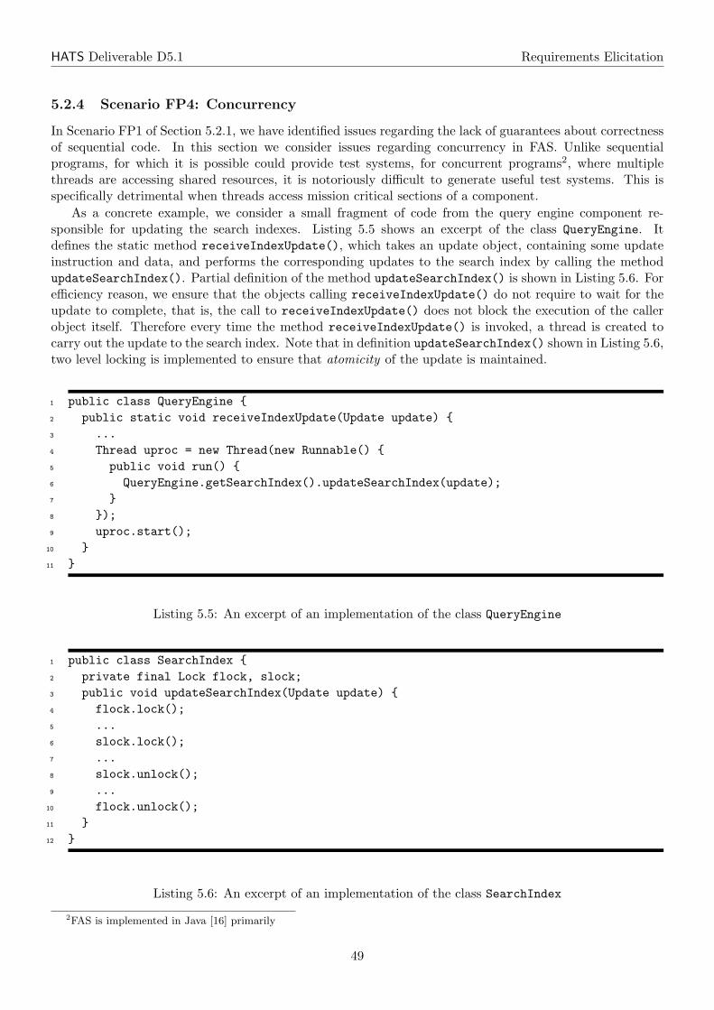
HATS Deliverable D5.1 Requirements Elicitation
5.2.4 Scenario FP4: Concurrency
In Scenario FP1 of Section 5.2.1, we have identified issues regarding the lack of guarantees about correctnessof sequential code. In this section we consider issues regarding concurrency in FAS. Unlike sequentialprograms, for which it is possible could provide test systems, for concurrent programs2, where multiplethreads are accessing shared resources, it is notoriously difficult to generate useful test systems. This isspecifically detrimental when threads access mission critical sections of a component.
As a concrete example, we consider a small fragment of code from the query engine component re-sponsible for updating the search indexes. Listing 5.5 shows an excerpt of the class QueryEngine. Itdefines the static method receiveIndexUpdate(), which takes an update object, containing some updateinstruction and data, and performs the corresponding updates to the search index by calling the methodupdateSearchIndex(). Partial definition of the method updateSearchIndex() is shown in Listing 5.6. Forefficiency reason, we ensure that the objects calling receiveIndexUpdate() do not require to wait for theupdate to complete, that is, the call to receiveIndexUpdate() does not block the execution of the callerobject itself. Therefore every time the method receiveIndexUpdate() is invoked, a thread is created tocarry out the update to the search index. Note that in definition updateSearchIndex() shown in Listing 5.6,two level locking is implemented to ensure that atomicity of the update is maintained.
1 public class QueryEngine {2 public static void receiveIndexUpdate(Update update) {3 ...4 Thread uproc = new Thread(new Runnable() {5 public void run() {6 QueryEngine.getSearchIndex().updateSearchIndex(update);7 }8 });9 uproc.start();
10 }11 }
Listing 5.5: An excerpt of an implementation of the class QueryEngine
1 public class SearchIndex {2 private final Lock flock, slock;3 public void updateSearchIndex(Update update) {4 flock.lock();5 ...6 slock.lock();7 ...8 slock.unlock();9 ...
10 flock.unlock();11 }12 }
Listing 5.6: An excerpt of an implementation of the class SearchIndex
2FAS is implemented in Java [16] primarily
49
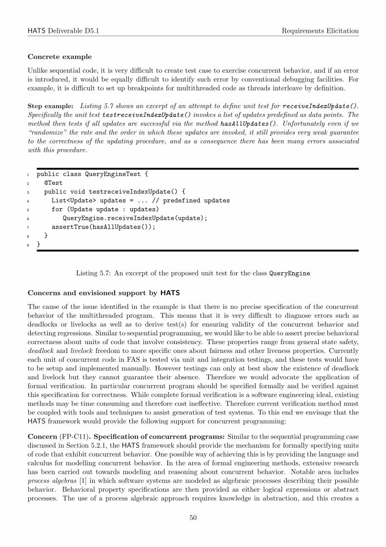
HATS Deliverable D5.1 Requirements Elicitation
Concrete example
Unlike sequential code, it is very difficult to create test case to exercise concurrent behavior, and if an erroris introduced, it would be equally difficult to identify such error by conventional debugging facilities. Forexample, it is difficult to set up breakpoints for multithreaded code as threads interleave by definition.
Step example: Listing 5.7 shows an excerpt of an attempt to define unit test for receiveIndexUpdate().Specifically the unit test testreceiveIndexUpdate() invokes a list of updates predefined as data points. Themethod then tests if all updates are successful via the method hasAllUpdates(). Unfortunately even if we“randomize” the rate and the order in which these updates are invoked, it still provides very weak guaranteeto the correctness of the updating procedure, and as a consequence there has been many errors associatedwith this procedure.
1 public class QueryEngineTest {2 @Test3 public void testreceiveIndexUpdate() {4 List<Update> updates = ... // predefined updates5 for (Update update : updates)6 QueryEngine.receiveIndexUpdate(update);7 assertTrue(hasAllUpdates());8 }9 }
Listing 5.7: An excerpt of the proposed unit test for the class QueryEngine
Concerns and envisioned support by HATS
The cause of the issue identified in the example is that there is no precise specification of the concurrentbehavior of the multithreaded program. This means that it is very difficult to diagnose errors such asdeadlocks or livelocks as well as to derive test(s) for ensuring validity of the concurrent behavior anddetecting regressions. Similar to sequential programming, we would like to be able to assert precise behavioralcorrectness about units of code that involve consistency. These properties range from general state safety,deadlock and livelock freedom to more specific ones about fairness and other liveness properties. Currentlyeach unit of concurrent code in FAS is tested via unit and integration testings, and these tests would haveto be setup and implemented manually. However testings can only at best show the existence of deadlockand livelock but they cannot guarantee their absence. Therefore we would advocate the application offormal verification. In particular concurrent program should be specified formally and be verified againstthis specification for correctness. While complete formal verification is a software engineering ideal, existingmethods may be time consuming and therefore cost ineffective. Therefore current verification method mustbe coupled with tools and techniques to assist generation of test systems. To this end we envisage that theHATS framework would provide the following support for concurrent programming:
Concern (FP-C11). Specification of concurrent programs: Similar to the sequential programming casediscussed in Section 5.2.1, the HATS framework should provide the mechanism for formally specifying unitsof code that exhibit concurrent behavior. One possible way of achieving this is by providing the language andcalculus for modelling concurrent behavior. In the area of formal engineering methods, extensive researchhas been carried out towards modeling and reasoning about concurrent behavior. Notable area includesprocess algebras [1] in which software systems are modeled as algebraic processes describing their possiblebehavior. Behavioral property specifications are then provided as either logical expressions or abstractprocesses. The use of a process algebraic approach requires knowledge in abstraction, and this creates a
50
HATS Deliverable D5.1 Requirements Elicitation
conceptual gap in between programming and modeling. A complementary approach is the development ofimplementation level language with rigorous formal foundation. This approach not only facilitates formalreasoning and associated tool support, but it is also much closer to general purpose programming languageslike Java [16]. Notable research result includes the development of Creol [21]. Creol is an experimentalhigh-level object-oriented language for distributed objects, and specification in Creol may be translated inMaude, for which various tools such as a theorem prover have been developed. However, either approachrequires mathematical knowledge, which cannot be assumed to be accessible to software developers andtesters. HATS should therefore incorporate usable techniques and tools to assist the generation of thesebehavioral properties such that formal specification becomes more amenable. (T1.1, T1.3, T1.5 and T4.3)
Concern (FP-C12). Verification of concurrent programs: Similar to sequential programming discussedin Section 5.2.1, the HATS framework should provide the mechanism to breach the gap between specifyingand verifying program correctness. The need for verification of behavioral properties has been identifiedin the concrete example above and the last paragraph has identified how concurrent behavioral propertiesmay be specified either algebraically or logically. For HATS framework to be a usable technology, it shouldincorporate techniques and automated tools (e.g. a model checker) to assist the verification process. Wewould also expect HATS to provide the mechanisms to (a) move both verification and respective specificationprocesses up to an abstract behavioral model level, and (b) be able to transfer verified properties back tothe code level. (T1.1, T1.4, T1.5, T3.2 and T4.3)
5.2.5 Scenario FP5: Using third party library
This scenario covers the case of FAS utilizing a third party library. During the development of FAS, thirdparty libraries are used to provide new features at a lower cost. For example, FAS uses many open sourcelibraries of the Apache project group.
In the next section we look at the utilization of a third party library for graph layout. This libraryprovides the algorithm to layout the graph representing the internal data structure for capturing businessrules in the rule engine; a brief overview of this graph layout feature is provided in Section 5.2.2.
Concrete example
Here we identify the typical steps for utilizing third party library. For each step we provide an examplerelating to the concrete example.
1. We identify specific information about the library, such as the version of the library that would beused; the public and interface methods exposed by the library as well as the corresponding (informal)documentation about the potential values and types of the input arguments and return values ofmethods.
Step example: We identify the version of the graph layout library, the method for creating a graphobject for laying out using the library, and the methods for adding nodes and edges to the graph object.We also identify the interface, which the library provides for implementing view navigation listeners.This allows inclusion of additional behavior when a node is clicked during graph visualization.
2. We implement the logic to transform the internal FAS rules data structure to one which could be usedby the graph layout library.
Step example: The diagnostic tool contains information about business rules stored in the ruleengine. We implement the transformation procedure to convert this information into a graph objectfor visualiation using the graph layout library.
3. We implement the code to invoke the graph layout library’s functionalities and integrate this code intoour existing component.
51
HATS Deliverable D5.1 Requirements Elicitation
Step example: To implement the code for setting up the layout, we studied demo programs providedby the graph layout library. This included identifying the correct algorithm provided by the libraryfor laying out the nodes of the graph, choosing the color scheme of the layout, and implementing thelistener for allowing the diagnostic tool to provide specific information based on the particular nodepressed. We also implemented the actual selection listener, that contains the programming logic torelate the diagnostic information with the node selected by a user in the graph visualisation.
4. We write unit tests and manual test cases for both the third party library’s as well as the programminglogic (glue code) that we have implemented for transforming data structure and invoking the librarylogic.
Step example: We implement unit tests to validate the following programming logic
• The transformation procedure for converting the business rules stored in the rule engine to thegraph object, which the library accepts. We must ensure that the graph repects how business rulesare related in the rule engine.
• The glue code for setting up the display and implementing the functionalities provided by theuser interface. Specifically when business rules store in the rule engine are visualized as a graph,each rule is represented as a node in the graph. We must ensure that when a node is selected,diagnostic information about that business rule is displayed correctly.
5. For every change and version update to the third party library, we review the changes manuallyby studying release note and updated documentation on the library’s API. We then implement thenecessary changes to the data transformation procedure and the glue code, as well as the changes tothe test systems. We execute the unit tests on the updated code before approving it to enter theproduct.
Step example: A change to the interface for adding nodes and edges to the graph object requirescorresponding changes to the transformation procedure. This updated procedure is then unit tested.
Concerns and envisioned support by HATS
The graph layout library documentation provides informal textual information about the functionality ofits interfaces as well as information about the potential side-effects that may arise from invoking theseinterfaces. It is necessary to be a able to provide a more precise description of the third party library’sfunctionality. Furthermore, we want to provide means to handle unanticipated changes to library’s internaland/or external behaviors. In the rest of this section we highlight specific issues about functional correctness,integration and testing from using third party libraries.
Functional correctness Our components must instantiate the libary classes and invoke its methodsthrough public interfaces according to the library’s “intended behavior”. That is, we must understand thefunctionality of each public interface, and the side-effects that may be caused by invoking these interfaces.Unlike Scenarios FP1 and FP2, where one might be able to provide precise behavioral description of methodsdown to class level, third party libraries are black boxes and as such we have no control with internal behavioror any behavioral changes. Therefore it is necessary to have the ability to model and specify behavior atthe interface level. To this end we envisage the HATS framework would provide the supports for addressingthese issues at the interface level :
Concern (FP-C13). Partial specification: Modeling of black box components and specification of behav-ioral properties such as pre/postcondition and invariants about them. Note that unlike the case presentedin Scenario FP1, it is often impossible to provide a complete behavioral specification of a black box com-ponent. Therefore, the HATS framework should allow models to have formal but incomplete specification.(T1.1, T1.5 and T4.3)
52
HATS Deliverable D5.1 Requirements Elicitation
Concern (FP-C14). Model mining: Derivation of models (model mining) from black box componentssuch that black box components may be described in the same way as white box components but with higherlevel of abstraction. (T3.2)
Concern (FP-C15). Evolution of black box components: Provision of guidance to model evolutiondue to unanticipated changes of black box components. Unlike the case introduced in Scenario FP1, it oftenis impossible to enforce boundary of changes to black box components. HATS framework should thereforeidentify changes to the black box components via model mining and provide useful information based onsome measure of model difference. (T3.1, T3.2, T3.3 and T3.5)
Integration To integrate a third party library into FAS, we manually provide the programming logic fortwo tasks: a) transforming the data models between the third party library and FAS, and b) coordinatingthe interaction between the library and FAS. This means the orders in which the library’s interface methodsare invoked.
We aim to factor out the glue code from the components interacting with the third party library. Thiswould allow better management of the glue code as well as adaptation to changes the third party library’sAPIs. While integration of new components has been addressed in Section 5.2.2, it is more difficult toanticipate the changes of the third party library. These unanticipated changes would make the integrationof the library to FAS much harder. To this end we envisage the HATS framework would provide the followingsupports:
Concern (FP-C16). Modeling data transformation: Modeling of the transformation between the datamodels of the third party library and that of FAS. For doing so, the HATS framework should provide(guided) code generation for implementing the transformation procedure. In our concrete example, giventhat we have a specification of the abstract syntax of the internal data structure of the rule engine and theabstract syntax of the graph object for layout, it should be possible to specify declaratively the rules fortransforming between these data models. This declarative specification could then be used to generate theimplementation code of the transformation. (T1.1, T1,4, T1.5 and T4.3)
Concern (FP-C17). Modeling interactions with black box components: Modeling of interactingbehavior between black box components and the rest of the systems. The HATS framework should beable to provide (guided) generation for the program code for handling the interaction between the blackbox components and the rest of the systems. In our concrete example in Section 5.2.5, we can see how itmay be difficult to validate the correctness of program code for a) transforming the data models betweenthe third party library and FAS, and b) coordinating the interaction between the library and FAS. Thisbecomes extremely difficult without a precise specification of the program code. Therefore we must firstprovide a formal specification of the interacting behavior between the third party library and FAS. TheHATS framework should then provide a tool support to assist the generation of the program code. (T1.1,T1.4, T1.5 and T4.3)
Concern (FP-C18). Propagation of changes: Modeling evolution due to unanticipated changes to blackbox components. Specifically evolution must be formally specified and properly propagated to the modelsof the program code for a) transforming the data models between the third party library and FAS, and b)interacting behavior between the third party library and FAS. Similar to the evolution of test systems, howevolution are propagated to the program code must be formally studied. This is so that evolutions couldmaintain consistency property. (T3.1, T3.2, T3.3 and T3.5)
Testing In Section 5.2.3, we have identified the need for the HATS framework to provide methodologyand technique to assist the generation of test systems for individual components. This requirement shouldbe extended to third party libraries. Specifically the HATS framework should provide support to assistthe generation of the test system for the program code for transforming data models between the libraryand FAS and for coordinating their interaction. The problem with testing behavior involving third party
53
HATS Deliverable D5.1 Requirements Elicitation
libraries is that tests are often written independently from the third party library’s “specification”. Thismeans it becomes notoriously difficult to ensure that we do not get false positive results. Furthermore, it isvery difficult to make changes to the test system while preserving consistency properties. To this end weenvisage the HATS framework would provide the following:
Concern (FP-C19). Test case generation: Provision of (guided) code generation of test systems based onproperties like compatibility specified using the HATS framework. Unlike maintaining consistent evolutionof white box components, it is more difficult to prove total correctness of black box components. In ourconcrete example, instead of manually implementing unit tests for the graph layout library and correspondingtransformation procedures and glue code, once a partial specification of the library interfaces has beenobtained, the HATS framework should be able to provide guidance for generating unit tests and manualintegrated test cases for rule engine interface as well as the interaction between the rule engine and thediagnostic tool. (T1.1,T1.4,T3.1,T3.4 and T3.5)
5.2.6 Scenario FP6: Performance
We now consider the scenario, which covers the performance issues that arise in the development process ofFAS. In the current development of FAS, there are two main metrics for performance benchmark: responsetime and queries per second. Those two elements form the FAS’s service level agreement.
Response time For an individual interaction with FAS, the main unit of measurement is response time.In particular it is the time it takes for a request to enter FAS and FAS to prepare a response toreturn to the user. Note that this is not the total time an interaction would take. FAS is a server-based software system. Therefore clients would normally implement specialised applications to supportsuch interaction. Consequently the computation of such applications would add overhead to the totalresponse time. Other overheads such as network latency would also contribute to the total responsetime.
Queries per second FAS is a server-based software system, which provides the capability to allow theclient to serve multiple requests concurrently. Queries per second is the number of requests completedby FAS per second. Note that this measurement is orthogonal to response time of individual requestand as such does not imply bounds to response time. For example, if FAS receives ≥ 20 requests persecond, it guarantees completion of ≥ 20 requests per second, that is, 20 queries per second, while theresponse time of individual request might take up to 200 milliseconds to complete.
As a concrete example, we study the development process of FAS, in particular we look at how perfor-mance analysis is carried out in Fredhopper.
Concrete example
In this section we describe how the performance of a particular functionality of FAS is analysed. Tomaintain the service level agreement, rigorous performance analysis has to be carried out at different levelsof granularity. During performance analysis a library of stress test cases are executed. Each test case definesthe workload, number of requests as well as where and when measurements are taken. Measurements aretaken for certain units of activity; here an activity is a sequence of instructions executed in FAS. For eachactivity, the following measurements are taken:
• Activity duration – This is the amount of time an activity takes to complete. This is measured bytaking a timestamp via System.currentTimeMillis() before and after the execution of the activity.
• Triggered activity duration – If an activity takes longer than expected, that is, longer than its thresholdvalue.
54
HATS Deliverable D5.1 Requirements Elicitation
• Activity occurrences – This measures the number of times and/or the number of locations where thecompletion of a particular activity may be recorded.
Each piece of measurement is identified with an activity. Identification is in terms of source code location.
• Stack trace location – Stack trace location provides accurate location in the source code, Since theprocedure for obtaining a stack trace of the current thread by calling getStackTrace() of the currentthread object would cost several milliseconds, this would be taken into consideration when carryingout analysis.
• User-defined location – A unique identifier, specified by the developer/tester, could be assigned to aparticular location
• Request identifier – This is a unique identifier composed of identifier of the current thread and aninteger specifying the number unique of requests processed by this thread.
For every measurement we produce an individual report containing the measurment’s unique identi-fier, its value, and the location where it is taken. Certain measurements may be aggregated, for example,if it measures the number of events at the same location. For every test case, some standard statisticalcalculations (average, standard deviation etc.) are made on the set of measurements obtained, and alsocorresponding (average) response time and (average) queries per second are obtained.
Step example: FAS defines a PageServlet class, which is a subclass of HttpServlet3, for creating afrontend web page for response for FAS. It overrides the method doGet(), which is called by the server(via the service method) to allow a servlet to handle a GET request. We would like to measure the time aGET request [18] would take for FAS to serve. For this measurement instructmentations are inserted at thebeginning and the end of the doGet() method body.
Concerns and envisioned support by HATS
The method for performance analysis described in the example above has a number of shortcomings. It istime consuming, a stress test case might be long-running, ranging from 30 minutes to several hours, andthis is not scalable under constant changes to the software system behavior such as adding new feature ormodifying existing ones. It is not exhaustive, test cases cannot provide complete guarantee on performancerequirements. It is not extensible, performance requirements are currently hard wired rather modeleddeclaratively and the model for specifying requirements is not compositional. To this end we envisage theHATS framework would provide the theory and tool support for the following:
Concern (FP-C20). Specification and analysis of Performance requirements: The HATS frameworkshould provide the mechanism and analysis technique for formally specifying performance requirement andresource guarantee of units of code. Proposed method should both be declarative and extensible by meansof compositionality. In the area of formal cost analysis [26, 12, 2], a program’s cost function are a set of costrelations, each defined by a set of recurrence equations, in which cost of a program is defined as a function ofits input data size. However the formulation of this model requires knowledge, which cannot be assumed tobe accessible to software developers and testers. HATS should therefore also incorporate usable techniquesand tools to assist the generation of cost models such that formal specification of performance requirementmight become more amenable. (T4.2)
Concern (FP-C21). Verification of performance requirement: The HATS framework should providethe mechanism to breach the gap between specifying and verifying performance requirement and resourceguarantees. The need for formal and approximate verification of performance requirement has been identifiedto overcome the shortcoming of the inexaustive method of stress testing. This is where performance and
3An abstract Jave class to be subclassed to create an HTTP servlet suitable for a Web site.
55
HATS Deliverable D5.1 Requirements Elicitation
resource guarantee of programs are specified in program logic [3], and then formally proved for correctness.Similar to specification of functional requirements, HATS should incorporate usable techniques and tools toassist verification process. (T1.5 and T4.2)
5.3 Summary
In this chapter we have presented the industrial software system FAS and used general scenarios withconcrete examples to identify concerns and issues with the development and support process of FAS. Wethen suggest where in the HATS project these concerns and issues may be addressed. As mentioned at thebeginning of this chapter, corresponding detail requirement analyses for these scenarios and examples wouldbe carried out in Task 5.2, using which concrete requirements would be harvested for the HATS framework.
Specifically Scenarios FP1 and FP4 in Sections 5.2.1 and 5.2.4 identified concerns for verifications ofsequential and concurrent behavior; Scenario FP2 in Section 5.2.2 identified concerns for components inte-gration; Scenario FP3 in Section 5.2.3 identified concerns for with generation and evolution of test systems;Scenario FP5 in Section 5.2.5 identified concerns for the utilization of third party libraries, and ScenarioFP6 in Section 5.2.6 concerned performance analysis. Table 5.1 gives a summary of the concerns harvestedfrom this case study and Table 5.2 shows the relationship between concerns identified in this case study andtasks to be carried out in the HATS project.
56
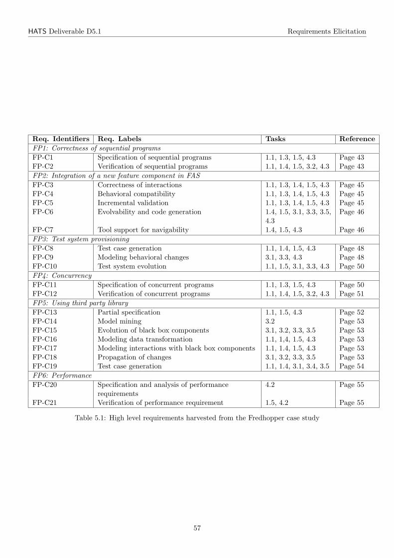
HATS Deliverable D5.1 Requirements Elicitation
Req. Identifiers Req. Labels Tasks ReferenceFP1: Correctness of sequential programsFP-C1 Specification of sequential programs 1.1, 1.3, 1.5, 4.3 Page 43FP-C2 Verification of sequential programs 1.1, 1.4, 1.5, 3.2, 4.3 Page 43FP2: Integration of a new feature component in FASFP-C3 Correctness of interactions 1.1, 1.3, 1.4, 1.5, 4.3 Page 45FP-C4 Behavioral compatibility 1.1, 1.3, 1.4, 1.5, 4.3 Page 45FP-C5 Incremental validation 1.1, 1.3, 1.4, 1.5, 4.3 Page 45FP-C6 Evolvability and code generation 1.4, 1.5, 3.1, 3.3, 3.5,
4.3Page 46
FP-C7 Tool support for navigability 1.4, 1.5, 4.3 Page 46FP3: Test system provisioningFP-C8 Test case generation 1.1, 1.4, 1.5, 4.3 Page 48FP-C9 Modeling behavioral changes 3.1, 3.3, 4.3 Page 48FP-C10 Test system evolution 1.1, 1.5, 3.1, 3.3, 4.3 Page 50FP4: ConcurrencyFP-C11 Specification of concurrent programs 1.1, 1.3, 1.5, 4.3 Page 50FP-C12 Verification of concurrent programs 1.1, 1.4, 1.5, 3.2, 4.3 Page 51FP5: Using third party libraryFP-C13 Partial specification 1.1, 1.5, 4.3 Page 52FP-C14 Model mining 3.2 Page 53FP-C15 Evolution of black box components 3.1, 3.2, 3.3, 3.5 Page 53FP-C16 Modeling data transformation 1.1, 1,4, 1.5, 4.3 Page 53FP-C17 Modeling interactions with black box components 1.1, 1.4, 1.5, 4.3 Page 53FP-C18 Propagation of changes 3.1, 3.2, 3.3, 3.5 Page 53FP-C19 Test case generation 1.1, 1.4, 3.1, 3.4, 3.5 Page 54FP6: PerformanceFP-C20 Specification and analysis of performance
requirements4.2 Page 55
FP-C21 Verification of performance requirement 1.5, 4.2 Page 55
Table 5.1: High level requirements harvested from the Fredhopper case study
57
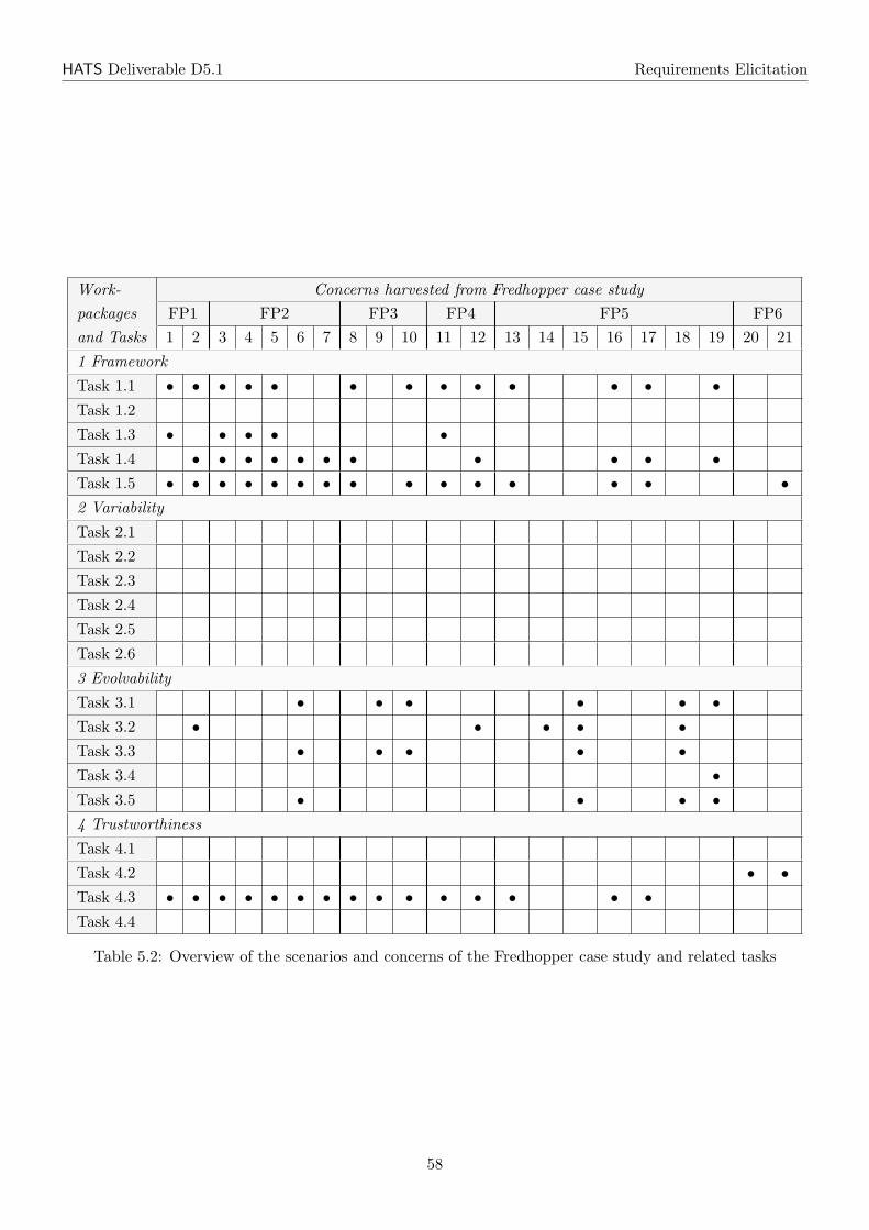
HATS Deliverable D5.1 Requirements Elicitation
Work- Concerns harvested from Fredhopper case studypackages FP1 FP2 FP3 FP4 FP5 FP6and Tasks 1 2 3 4 5 6 7 8 9 10 11 12 13 14 15 16 17 18 19 20 21
1 Framework
Task 1.1 • • • • • • • • • • • • •Task 1.2
Task 1.3 • • • • •Task 1.4 • • • • • • • • • • •Task 1.5 • • • • • • • • • • • • • • •2 Variability
Task 2.1
Task 2.2
Task 2.3
Task 2.4
Task 2.5
Task 2.6
3 Evolvability
Task 3.1 • • • • • •Task 3.2 • • • • •Task 3.3 • • • • •Task 3.4 •Task 3.5 • • • •4 Trustworthiness
Task 4.1
Task 4.2 • •Task 4.3 • • • • • • • • • • • • • • •Task 4.4
Table 5.2: Overview of the scenarios and concerns of the Fredhopper case study and related tasks
58
Chapter 6
Summary
This document provides the description of abstract requirements for the HATS method. The requirements aredivided into methodological requirements, which are described from an industry and a research perspective,and concrete requirements, coming from different scenarios of the three case studies.
The methodological requirements can be seen as general high-level requirements, which should be sup-ported by the HATS method in order to be accepted by the research community and by industry.
The requirements of the case studies are elicited by means of different scenarios, which cover differentchallenges and problems for each case study. As the three case studies greatly differ in profile, size, andapplication area, they cover very different aspects of the software development life cycle. Tables 3.2, 4.2and 5.2 together give the complete overview of the scenarios and concerns identified via the case studiesand their corresponding work packages and tasks. As can be seen, the scenarios and concerns provide acomplete task coverage, where the different case studies vary in focus.
The Trading System case study is an academic system. It is small enough to be completely modeledby ABS. It will be used to apply nearly all techniques developed in HATS. The different scenarios of theTrading System case study are thus designed to cover most problem domains, which are addressed by HATS.In particular, it will be used to evaluate tasks that are not addressed by the other two case studies. However,being an academic system it cannot serve as a realistic example from industry, as the elicited requirementsare artificial and not driven by real customer needs.
The Virtual Office of the Future case study is a research system, coming from a semi-industrial domain.The system is in particular challenging for ABS because of its highly distributed system structure. Thescenarios of this case study have no main focus and cover aspects of all work packages. As the VOFcase study is developed by standard industry methods, it will be an important case study to validate theintegration of HATS framework into existing development methods.
Finally, the Fredhopper case study is a system used and developed in industry. This case study differsin two main points from the other ones. The first is that it is in active use by many customers and that itis constantly evolving and adapted. The second is, being an industry system, it relies on many third partysoftware components. Thus it cannot be assumed that the whole program source is available. This introducesseveral interesting challenges to the HATS framework, which might, however, not all be solvable in the scopeof HATS. In particular, it requires that the ABS language is able to modularly describe and verify certainparts of a software system and to abstract from a concrete environment and the implementation of othersoftware parts. The main focus of the case study, however, is evolvability. In particular, the Fredhopper casestudy provides evolution steps, which are driven by customer needs and are thus not artificial. Evolution inthe Fredhopper system is critical in several aspects. First, evolution is required for Fredhopper in order tokeep their product competitive. Second, evolution has to be applied to systems, which are already deployedand are running. And third, evolution must not introduce bugs, resulting in down times of systems deployedat customers.
Deliverable D5.1 is the starting point for the validation of the HATS framework. The requirementscollected in this document are described on a rather abstract level. These requirements will be refined and
59
HATS Deliverable D5.1 Requirements Elicitation
scoped in the later validation phases, starting with D5.2, which will validate the Core ABS language.
60
Bibliography
[1] L. Aceto and A. D. Gordon, editors. Proceedings of the Workshop Algebraic Process Calculi: The FirstTwenty Five Years and Beyond, volume 162 of ENTCS, 2006.
[2] Elvira Albert, Puri Arenas, Samir Genaim, German Puebla, and Damiano Zanardini. Cost Analysisof Java Bytecode. In Rocco De Nicola, editor, 16th European Symposium on Programming, ESOP’07,volume 4421 of Lecture Notes in Computer Science, pages 157–172. Springer-Verlag, March 2007.
[3] D. Aspinall, L. Beringer, M. Hofmann, H-W. Loidl, and A. Momigliano. A program logic for resourceverification. In 17th International Conference on Theorem Proving in Higher Order Logics, volume3223 of LNCS, 2004.
[4] C. Atkinson, J. Bayer, C. Bunse, E. Kamsties, O. Laitenberger, R. Laqua, D. Muthig, B. Paech,J. Wust, and J. Zettel. Component-based product line engineering with UML. Addison-Wesley LongmanPublishing Co., Inc., Boston, MA, USA, 2002.
[5] J. Bayer, C. Gacek, D. Muthig, and T. Widen. Pulse-i: Deriving instances from a product line in-frastructure. Engineering of Computer-Based Systems, IEEE International Conference on the, 0:237,2000.
[6] S. Becker, W. Hasselbring, A. Paul, M. Boskovic, H. Koziolek, J. Ploski, A. Dhama, H. Lipskoch,M. Rohr, D. Winteler, S. Giesecke, R. Meyer, M. Swaminathan, J. Happe, M. Muhle, and T. Warns.Trustworthy software systems: a discussion of basic concepts and terminology. SIGSOFT SoftwareEngineering Notes0, 31(6), 2006.
[7] C. Canal, E. Pimentel, and J. M. Troya. Compatibility and inheritance in software architectures.Science of Computer Programming, 41(2):105–138, 2001.
[8] S. Carpineti, G. Castagna, C. Laneve, and L. Padovani. A formal account of contracts for web services.In WS-FM’06, volume 4184 of LNCS, 2006.
[9] P. Clements and L. Northrop. Software Product Lines: Practices and Patterns. Addison WesleyLongman, 2001.
[10] The CoCoME Website, July 2009. http://www.cocome.org.
[11] K. Czarnecki, U. Eisenecker, and K. Czarnecki. Generative Programming: Methods, Tools, and Appli-cations. Addison-Wesley Professional, 2000.
[12] S. K. Debray and N. W. Lin. Cost analysis of logic programs. TOPLAS, 15, 1993.
[13] Sophia Drossopoulou, editor. ECOOP 2009 - Object-Oriented Programming, 23rd European Conference,Genoa, Italy, July 6-10, 2009. Proceedings, volume 5653 of Lecture Notes in Computer Science. Springer,2009.
[14] C. Forgy. On the efficient implementation of production systems. PhD thesis, Carnegie-Mellon Univer-sity, 1979.
61
HATS Deliverable D5.1 Requirements Elicitation
[15] Fredhopper Product. http://www.fredhopper.com.
[16] J. Gosling, B. Joy, and G. Steele. The Java Language Specification. Addison-Wesley, 1996.
[17] Highly Adaptable and Trustworthy Software using Formal Methods, March 2009. http://www.hats-project.eu.
[18] Hypertext Transfer Protocol – HTTP/1.1. http://www.w3.org/Protocols/rfc2616/rfc2616.html.
[19] D. Jackson. A direct path to dependable software. Comm. ACM, 52(4):78–88, 2009.
[20] M. Jazayeri, A. Ran, and F. van der Linden. Software architecture for product families: principles andpractice. Addison-Wesley Longman Publishing Co., Inc., Boston, MA, USA, 2000.
[21] Einar Broch Johnsen, Olaf Owe, and Ingrid Chieh Yu. Creol: A type-safe object-oriented model fordistributed concurrent systems. Theoretical Computer Science, 365(1–2):23–66, November 2006.
[22] G. Kiczales, J. Lamping, A. Mendhekar, C. Maeda, C. Lopes, J. Loingtier, and J. Irwin. Aspect-orientedprogramming. In Proceedings of the European Conference on Object-Oriented Programming, volume1241 of LNCS, 1997.
[23] C. Larman. Applying UML and Patterns: An Introduction to Object-Oriented Analysis and Design andIterative Development. Prentice Hall, 3rd edition, 2004.
[24] D. Muthig. A Lightweight Approach Facilitating an Evolutionary Transition Towards Software ProductLines. PhD thesis, University of Kaiserslautern, 2002.
[25] K. Pohl, G. Bockle, and F. Van Der Linden. Software Product Line Engineering: Foundations, Princi-ples, and Techniques. Springer, Heidelberg, 2005.
[26] F. A. Rabhi and G. A. Manson. Using complexity functions to control parallelism in functional pro-grams. Technical Report TR. CS-90-1, Department of Computer Science, University of Sheffield, UK,1990.
[27] A. Rausch, R. Reussner, R. Mirandola, and F. Plasil, editors. The Common Component Modeling Exam-ple: Comparing Software Component Models [result from the Dagstuhl research seminar for CoCoME,August 1-3, 2007], volume 5153 of LNCS. Springer, 2008. Preliminary version of the chapter describingthe Trading System is available at: http://agrausch.informatik.uni-kl.de/CoCoME/downloads/documentation/cocome.pdf.
[28] J. N. Reed, J. E. Sinclair, and A. W. Roscoe. Responsiveness of interoperating components. Form.Asp. Comput., 16(4):394–411, 2004.
[29] Steffen Thiel and Klaus Pohl, editors. Software Product Lines, 12th International Conference, SPLC2008, Limerick, Ireland, September 8-12, 2008, Proceedings. Second Volume (Workshops). Lero Int.Science Centre, University of Limerick, Ireland, 2008.
[30] Research Highlight: Virtual Office of the Future. http://www.iese.fraunhofer.de/research/vof/vof.jsp.
62
Glossary
Terms and Abbreviations
ABS Abstract Behavioral Specification language. An executable class-based, concurrent, object-orientedmodeling language based on Creol, created for the HATS project.
AE See Application engineering
API Application programming interface, provided by a component to enable communication with othercomponents.
Application engineering Application engineering is a process that builds a single product by reusingartifacts in the product line artifact base.
Artifact An artifact in a product line is the output of the product line engineering process. Artifactsencompass requirements, architecture, components, tests etc.
ELT Extract, Transform and Load Toolkit.
Family engineering Family engineering is a process that builds reusable artifacts that are stored in aproduct line artifact base. See also Product line artifact base.
FAS See Fredhopper access server
FE See Family engineering
Feature Generally, an increment in software functionality. On the level of feature models it is merely alabel with no inherent semantic meaning.
Feature model An expression of the variability within product lines. Abstractly it may be seen as asystem of constraints on the set of possible feature configurations.
Fredhopper access server Fredhopper access server is a component-based, service-oriented and server-based software system, which provides search and merchandising IT services to e-Commerce companiessuch as large catalog traders, travel booking, managers of classified, etc.
PLE See Product line engineering.
Product line artifact base A repository in a software product line containing all reusable artifacts.
Product line engineering A development methodology for software product family. It splits develop-ment into Family engineering and Application engineering processes. See also Family engineering andApplication engineering.
Queries per second Queries per second is the number of requests completed by FAS per second. See alsoFAS.
63
HATS Deliverable D5.1 Requirements Elicitation
Response time Response time is the time that is required for a request to enter FAS and FAS to preparea response to return to the user.
Service level agreement Service level agreement is a part of a service contract where the level of serviceis formally defined.
Software product family A family of software systems with well-defined commonalities and variabilities.
SWPF See Software product family.
UML Unified Modeling Language
Virtual office of the future A P2P framework that enables office workers to perform their office tasksseamlessly independent of their current location.
VOF See Virtual office of the future
64


![Title: A summary of PICOS WP3 sub-phase 3.1 deliverables · 2010. 10. 20. · deliverable D5.1 [D5.1]; and deliverable D3.3.1, concerned with the community prototype described in](https://static.fdocuments.in/doc/165x107/603974a6825a34653b5347f0/title-a-summary-of-picos-wp3-sub-phase-31-2010-10-20-deliverable-d51-d51.jpg)