Basement Improvement - Springville
2
Basement Improvement Community Development Building Division Common code applications that are a part of a basement remodel that are commonly missed: Plumbing Nail plating of plumbing too close to the stud face. (1 1/2 inches or less) Inadequate toilet alcove opening due to cabinet loca- tion (30 inches upon finish) Access for plumbing cleanouts not maintained after drywall application (18 inch clearance) Concealing auto-vent device in wall cavity Caulking of plumbing fixtures for sanitation Proper support on pipe work Installation of corrugated piping is not permitted Electrical Nail plating of conductors less than 1 1/4 inches to stud face (measured to opening edge) Securing of electrical cables at the box location (8 inches) Wrong size wire or incorrect wiring method on re- stroom circuits. (12 a.w.g. wire for 20 amp circuit, dedicated) Lack of arc-fault protection on bedroom circuits Failure to update panel with new circuit information Smoke detectors wired with appropriate cable assem- bly (14-3 with ground) and interconnected to existing Carbon monoxide detector (installed in hall, intercon- nected with smoke detectors) Maximum spacing of wall receptacles of 12 feet Heating/cooling Inadequate support for ducting materials Lack of return air in basement level Failure to seal ducting joints Venting bathrooms to outside if lacking window Door opening from mechanical room into bedroom or bathroom without sealed door Ducting used for drywall support is prohibited Individual runs for air supply to living spaces Return air cannot be located in restroom locations Framing Draft stop at top of wall or every ten feet horizontally and at locations where drops tie into walls. Use of gypsum behind tile in a shower surround not permitted Use of green board gypsum in ceiling with additional blocking (requires 12 inch on center support) Block shower pan locations with 2X6 use of treated or decay resistant wood in contact with concrete for bottom plate. Appropriate sized headers for bearing locations Provide backing at all corners and ceiling drop locations Ceiling dry wall attachment of 12 inch max spacing for screw and wall attachment of 16 inches. Install handrails/guardrails as necessary Building Design Egress windows for bedrooms require 5.7 square feet with minimum of 20” for width and 24” in height. Egress ladders required if window wells exceed 44 inch depth Window frame height cannot exceed 44 inch height from finish floor Exterior clearance for wells require 9 square feet and minimum of 36 inches depth. 36 inch clearance required under decks and overhangs for egress locations. Cover window wells if within 36 inches of walk- way Ceiling height of 6’8” for habitable locations 6’4” allowed for beams/girders Energy Code Window u-value minimum of 0.35 Insulation R value of 13 for exterior walls Insulate duct work in unconditioned areas with R-8 Insulate walls adjoining conditioned- unconditioned areas. 110 S. Main Street Springville, UT 84663 (801) 489-2704 www.springville.org/permits Building Requirements Changing the use of a residential unfinished basement to a habitable location, adding electrical, plumbing, or heating systems all require application and permitting prior to starting of the projects. The State of Utah has adopted the International Residen-tial Code for use within our State. This is an example of the information that will be needed to determine compliance with these laws. Basement improvement building permit application process Complete and submit the building permit application. The application is available at the City Offices in the Building department or online at www.springville.org/permits. Submit electronic copies of building plan, construction drawings, elevations and engineering if needed as well as the following: (see next page)
Transcript of Basement Improvement - Springville
Basement Improvement
Community Development Building Division
Common code applications that are a part of a
basement remodel that are commonly missed:
Plumbing
Nail plating of plumbing too close to the stud face. (11/2 inches or less)
Inadequate toilet alcove opening due to cabinet loca-tion (30 inches upon finish)
Access for plumbing cleanouts not maintained afterdrywall application (18 inch clearance)
Concealing auto-vent device in wall cavity Caulking of plumbing fixtures for sanitation Proper support on pipe work Installation of corrugated piping is not permitted
Electrical
Nail plating of conductors less than 1 1/4 inches tostud face (measured to opening edge)
Securing of electrical cables at the box location (8inches)
Wrong size wire or incorrect wiring method on re-stroom circuits. (12 a.w.g. wire for 20 amp circuit,dedicated)
Lack of arc-fault protection on bedroom circuits Failure to update panel with new circuit information Smoke detectors wired with appropriate cable assem-
bly (14-3 with ground) and interconnected to existing Carbon monoxide detector (installed in hall, intercon-
nected with smoke detectors) Maximum spacing of wall receptacles of 12 feet
Heating/cooling
Inadequate support for ducting materials Lack of return air in basement level Failure to seal ducting joints Venting bathrooms to outside if lacking window Door opening from mechanical room into bedroom or
bathroom without sealed door Ducting used for drywall support is prohibited Individual runs for air supply to living spaces Return air cannot be located in restroom locations
Framing
Draft stop at top of wall or every ten feet horizontallyand at locations where drops tie into walls.
Use of gypsum behind tile in a shower surround notpermitted
Use of green board gypsum in ceiling with additionalblocking (requires 12 inch on center support)
Block shower pan locations with 2X6 use of treated or decay resistant wood in contact
with concrete for bottom plate. Appropriate sized headers for bearing locations Provide backing at all corners and ceiling drop
locations Ceiling dry wall attachment of 12 inch max
spacing for screw and wall attachment of 16inches.
Install handrails/guardrails as necessary
Building Design
Egress windows for bedrooms require 5.7 squarefeet with minimum of 20” for width and 24” inheight.
Egress ladders required if window wells exceed44 inch depth
Window frame height cannot exceed 44 inchheight from finish floor
Exterior clearance for wells require 9 square feetand minimum of 36 inches depth.
36 inch clearance required under decks andoverhangs for egress locations.
Cover window wells if within 36 inches of walk-way
Ceiling height of 6’8” for habitable locations 6’4” allowed for beams/girders
Energy Code
Window u-value minimum of 0.35 Insulation R value of 13 for exterior walls Insulate duct work in unconditioned areas with
R-8 Insulate walls adjoining conditioned-
unconditioned areas.
110 S. Main StreetSpringville, UT 84663
(801) 489-2704 www.springville.org/permits
Building Requirements
Changing the use of a residential unfinished basement to a habitable location, adding electrical, plumbing, or heating systems all require application and permitting prior to starting of the projects. The State of Utah has adopted the International Residen-tial Code for use within our State. This is an example of the information that will be needed to determine compliance with these laws.
Basement improvement building permit application process
Complete and submit the building permit application. The application is available at the City Offices in the Building department or online at www.springville.org/permits.
Submit electronic copies of building plan, construction drawings, elevations and engineering if needed as well as the following:
(see next page)
hbakker
Sticky Note
Marked set by hbakker
hbakker
Sticky Note
Marked set by hbakker
hbakker
Sticky Note
Marked set by hbakker
hbakker
Sticky Note
Marked set by hbakker
hbakker
Sticky Note
Marked set by hbakker
hbakker
Sticky Note
Marked set by hbakker
hbakker
Sticky Note
Marked set by hbakker
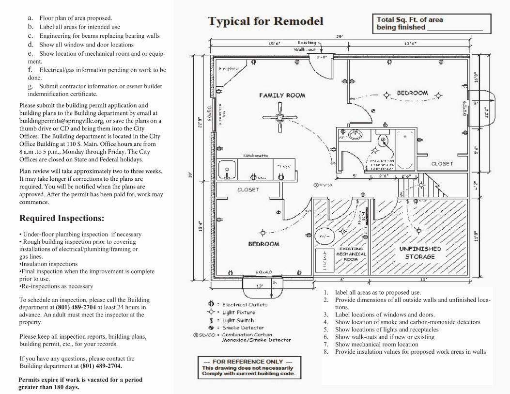
a. Floor plan of area proposed.b. Label all areas for intended usec. Engineering for beams replacing bearing wallsd. Show all window and door locationse. Show location of mechanical room and or equip-ment. f. Electrical/gas information pending on work to bedone. g. Submit contractor information or owner builderindemnification certificate.
Required Inspections:
• Under-floor plumbing inspection if necessary• Rough building inspection prior to coveringinstallations of electrical/plumbing/framing or gas lines.•Insulation inspections•Final inspection when the improvement is completeprior to use. •Re-inspections as necessary
1. label all areas as to proposed use.2. Provide dimensions of all outside walls and unfinished loca-
tions.3. Label locations of windows and doors.4. Show location of smoke and carbon-monoxide detectors5. Show locations of lights and receptacles6. Show walk-outs and if new or existing7. Show mechanical room location8. Provide insulation values for proposed work areas in walls
Please submit the building permit application and building plans to the Building department by email at [email protected], or save the plans on a thumb drive or CD and bring them into the City Offices. The Building department is located in the City Office Building at 110 S. Main. Office hours are from 8 a.m .to 5 p.m., Monday through Friday. The City Offices are closed on State and Federal holidays.
Plan review will take approximately two to three weeks. It may take longer if corrections to the plans are required. You will be notified when the plans are approved. After the permit has been paid for, work may commence.
To schedule an inspection, please call the Building department at (801) 489-2704 at least 24 hours in advance. An adult must meet the inspector at the property.
Please keep all inspection reports, building plans, building permit, etc., for your records.
If you have any questions, please contact the Building department at (801) 489-2704.
Permits expire if work is vacated for a period greater than 180 days.