
Barcak, R. G., Kraus, N. C., Lin, L., Smith, E. R., Heilman, D. J., … · Proceedings Coastal...
14
Barcak, R. G., Kraus, N. C., Lin, L., Smith, E. R., Heilman, D. J., and Thomas, R. C. 2007. Proceedings Coastal Sediments ’07 Conference, ASCE Press, Reston, VA, 1502- 1514. NAVIGATION IMPROVEMENTS, MOUTH OF THE COLORADO RIVER, TEXAS Ronnie G. Barcak 1 , Nicholas C. Kraus 2 , Lihwa Lin 2 , Ernest R. Smith 2 , Daniel J. Heilman 3 , Robert C. Thomas 3 1. U.S. Army Corps of Engineers, Galveston District, 2000 Fort Point Road, Galveston, TX, 77550, USA. [email protected] . 2. U.S. Army Engineer Research and Development Center, Coastal and Hydraulics Laboratory, 3909 Halls Ferry Road, Vicksburg, MS 39180-6199, USA. [email protected] . [email protected] . [email protected] . 3. HDR | Shiner Moseley and Associates, Inc., 555 N. Carancahua, Suite 1650, Corpus Christi, TX 78478, USA. [email protected] . [email protected] . Abstract: This paper describes an ongoing analysis of coastal and inlet processes at the mouth of the Colorado River Navigation Channel, Texas. A weir jetty system with impoundment basin down drift of the weir was constructed at the mouth of the Colorado River in 1985 to reduce the expected rate of dredging of the shallow-draft entrance navigation channel. The required rate of dredging has been about double the design estimate, however, due in part to diversion of the Colorado River away from its entrance to the Gulf of Mexico. A study is underway to better understand the processes involved, design a more efficient entrance, and provide the reduced dredging interval and volume originally desired, while placing the inlet processes within a regional sediment transport framework. INTRODUCTION The mouth of the Colorado River (MCR) is located on the Texas Gulf of Mexico coast approximately midway between Galveston and Corpus Christi (Fig. 1). It is a federally authorized shallow-draft navigation channel that experiences relatively weak water exchange between the Gulf of Mexico and East Matagorda Bay, connected through the 10.5-km (6.5 mile) long Colorado River Navigation Channel (CRNC) and the eastward section of the Gulf Intracoastal Waterway (GIWW). The flow system associated with the mouth of the Colorado River is separated from the Colorado River itself and (West)
Transcript of Barcak, R. G., Kraus, N. C., Lin, L., Smith, E. R., Heilman, D. J., … · Proceedings Coastal...

Barcak, R. G., Kraus, N. C., Lin, L., Smith, E. R., Heilman, D. J., and Thomas, R. C. 2007. Proceedings Coastal Sediments ’07 Conference, ASCE Press, Reston, VA, 1502-1514.
NAVIGATION IMPROVEMENTS, MOUTH OF THE COLORADO RIVER, TEXAS
Ronnie G. Barcak1, Nicholas C. Kraus2, Lihwa Lin2, Ernest R. Smith2,
Daniel J. Heilman3, Robert C. Thomas3
1. U.S. Army Corps of Engineers, Galveston District, 2000 Fort Point Road, Galveston,
TX, 77550, USA. [email protected]. 2. U.S. Army Engineer Research and Development Center, Coastal and Hydraulics
Laboratory, 3909 Halls Ferry Road, Vicksburg, MS 39180-6199, USA. [email protected]. [email protected]. [email protected].
3. HDR | Shiner Moseley and Associates, Inc., 555 N. Carancahua, Suite 1650, Corpus Christi, TX 78478, USA. [email protected]. [email protected].
Abstract: This paper describes an ongoing analysis of coastal and inlet processes at the mouth of the Colorado River Navigation Channel, Texas. A weir jetty system with impoundment basin down drift of the weir was constructed at the mouth of the Colorado River in 1985 to reduce the expected rate of dredging of the shallow-draft entrance navigation channel. The required rate of dredging has been about double the design estimate, however, due in part to diversion of the Colorado River away from its entrance to the Gulf of Mexico. A study is underway to better understand the processes involved, design a more efficient entrance, and provide the reduced dredging interval and volume originally desired, while placing the inlet processes within a regional sediment transport framework.
INTRODUCTION The mouth of the Colorado River (MCR) is located on the Texas Gulf of Mexico coast approximately midway between Galveston and Corpus Christi (Fig. 1). It is a federally authorized shallow-draft navigation channel that experiences relatively weak water exchange between the Gulf of Mexico and East Matagorda Bay, connected through the 10.5-km (6.5 mile) long Colorado River Navigation Channel (CRNC) and the eastward section of the Gulf Intracoastal Waterway (GIWW). The flow system associated with the mouth of the Colorado River is separated from the Colorado River itself and (West)

Report Documentation Page Form ApprovedOMB No. 0704-0188
Public reporting burden for the collection of information is estimated to average 1 hour per response, including the time for reviewing instructions, searching existing data sources, gathering andmaintaining the data needed, and completing and reviewing the collection of information. Send comments regarding this burden estimate or any other aspect of this collection of information,including suggestions for reducing this burden, to Washington Headquarters Services, Directorate for Information Operations and Reports, 1215 Jefferson Davis Highway, Suite 1204, ArlingtonVA 22202-4302. Respondents should be aware that notwithstanding any other provision of law, no person shall be subject to a penalty for failing to comply with a collection of information if itdoes not display a currently valid OMB control number.
1. REPORT DATE 2007 2. REPORT TYPE
3. DATES COVERED 00-00-2007 to 00-00-2007
4. TITLE AND SUBTITLE Navigation Improvements, Mouth of the Colorado River, Texas
5a. CONTRACT NUMBER
5b. GRANT NUMBER
5c. PROGRAM ELEMENT NUMBER
6. AUTHOR(S) 5d. PROJECT NUMBER
5e. TASK NUMBER
5f. WORK UNIT NUMBER
7. PERFORMING ORGANIZATION NAME(S) AND ADDRESS(ES) U.S. Army Engineer Research and Development Center,Coastal andHydraulics Laboratory,3909 Halls Ferry Road,Vicksburg,MS,39180-6199
8. PERFORMING ORGANIZATIONREPORT NUMBER
9. SPONSORING/MONITORING AGENCY NAME(S) AND ADDRESS(ES) 10. SPONSOR/MONITOR’S ACRONYM(S)
11. SPONSOR/MONITOR’S REPORT NUMBER(S)
12. DISTRIBUTION/AVAILABILITY STATEMENT Approved for public release; distribution unlimited
13. SUPPLEMENTARY NOTES Proceedings Coastal Sediments ’07 Conference, 13-17 May 2007, New Orleans, LA, ASCE Press, 1502-1514
14. ABSTRACT This paper describes an ongoing analysis of coastal and inlet processes at the mouth of the Colorado RiverNavigation Channel, Texas. A weir jetty system with impoundment basin down drift of the weir wasconstructed at the mouth of the Colorado River in 1985 to reduce the expected rate of dredging of theshallow-draft entrance navigation channel. The required rate of dredging has been about double the designestimate, however, due in part to diversion of the Colorado River away from its entrance to the Gulf ofMexico. A study is underway to better understand the processes involved, design a more efficient entrance,and provide the reduced dredging interval and volume originally desired, while placing the inlet processeswithin a regional sediment transport framework.
15. SUBJECT TERMS
16. SECURITY CLASSIFICATION OF: 17. LIMITATION OF ABSTRACT Same as
Report (SAR)
18. NUMBEROF PAGES
13
19a. NAME OFRESPONSIBLE PERSON
a. REPORT unclassified
b. ABSTRACT unclassified
c. THIS PAGE unclassified
Standard Form 298 (Rev. 8-98) Prescribed by ANSI Std Z39-18

2
Matagorda Bay through diversion of the river into the bay in 1992 as an environmental enhancement. Dual rubble mound jetties constructed in 1985 protect the entrance to the CRNC. The west jetty extends 333 m from the shoreline. The east jetty has a 333-m (1,090 ft) long weir section on its landward side with a sediment impoundment basin located westward of the weir. The entrance channel, 5 m deep by 65 m wide (17 ft by 200 ft), connects to the GIWW through a 4-m deep by 33-m wide (15 ft by 100 ft) channel.
28o 30
′N28
o 35′N
28o 40
′N28
o 45′N
28o 50
′N
96o05′W 96oW 95o55′W 95o50′W 95o45′W 95o40′W
Scale
03 3 6Kilometers
Longitude
Latit
ude
Gulf of Mexico
East Matagorda Bay
Matagorda Bay
Colorado River
GIWW
Colorado River Entrance
Boatlocks
Caney Creek
Live Oak Bayou
CRNC
Mitchell′s Cut
Parker′s Cut
ProposedSW Cut
[Rawlings]
[E. Mat]
Fig. 1. Location map for study site, Colorado River entrance, central Texas coast
The coastal and inlet processes at the MCR, including circulation, waves, and longshore transport were numerically simulated by Lin et al. (2001). Local-scale modeling of sediment transport of the existing condition has recently been undertaken to analyze potential alternatives to the existing design for enhancing control of sedimentation of the navigation channel. This paper discusses the ongoing study at the MCR, the history, present study efforts, and what might be done in the future. BACKGROUND Before 1930, East Matagorda Bay and Matagorda Bay comprised a single Matagorda Bay. The bay was divided in 1935, when a large river delta was formed and moved across the bay after a logjam was freed in the river between 1925 and 1929 (US Army Corps of Engineers (USACE) 1992). The Colorado River began discharging into the Gulf of Mexico in 1935. Dual rubble mound jetties were constructed in 1985 to protect the entrance to the CRNC. Several designs to modify the entrance channel were considered, with the weir jetty and impoundment basin design being judged the most cost effective for construction and subsequent dredging and bypassing of the sand

3
dredged from the deposition basin and channel. At the time of design (in the 1960s), review (1970s), and construction (1980s), the Colorado River discharged to the Gulf of Mexico. The overall hydraulic system of the MCR is complex because of tide and wind forcing, connection of the CRNC to East Matagorda Bay, possibility of opening the SW Corner Cut to East Matagorda Bay (Kraus and Militello 1999), and possibility of opening the presently closed Parkers Cut to Matagorda Bay (Fig. 1).
Fig. 2. Entrance of Colorado River Navigation Channel, TX
As originally designed, the sediment impoundment basin was located between the weir section and the entrance channel (Fig. 2). The impoundment basin accommodated sand bypassing to the down-drift beaches by means of a pipeline dredge, with discharge in the surf zone on the west side of the MCR. The basin was designed to hold a 2-year supply of sediment estimated at 460,000 m3 (600,000 cy) (USACE 1977). The jetties had to be placed at relatively large distance from each other to accommodate the deposition basin. The distance between the gulfward ends of the jetties is approximately 400 m (1,300 ft).
The Colorado River was rerouted in 1992 to discharge into Matagorda Bay through a diversion channel as part of an environmental enhancement project. A pair of locks was added to the GIWW at the junction of the Colorado River to mitigate the cross current at the intersection of the river and GIWW. As a result, the Colorado River was diverted

4
into Matagorda Bay, eliminating the river discharge as a means of scouring sediment from the entrance channel to the Gulf. The CRNC was thereby separated from the main river, but it is connected to the eastward section of the GIWW. Initial dredging of the impoundment basin was completed in 1990. Since then, the basin has filled more rapidly than designed. The entrance mouth has experienced excessive sediment shoaling, and spits form on both the east and west sides of the landward ends of the jetties, encroaching on the navigation channel. Figure 3 plots volume of sediment dredged in the basin and CRNC from 1990 to 2002 and indicates that the total volume of dredging annually is about 425,000 m3 (556,000 cy), approximately double the design estimate (in part due to contributions from the northern CRNC bottom and GIWW).
Fig. 3. Dredged volume at entrance of Colorado River Navigation Channel, TX
A 152-m (500 ft) long rock dike was constructed in September 2003 to function as a training structure for the deposition and reduce dredging requirements, as recommended by Kraus et al. (2003). Considered to be economically justified if it eliminated the need for one dredging cycle at annual frequency, it eliminated the need for almost two dredging cycles before being overwhelmed by wind-blow sand transport and swash-zone transport that occurred landward of the deposition basin during times of high water in the Gulf of Mexico. The sediment training structure was constructed shortly before the USACE was required to lower priority of maintaining shallow-draft channels, thereby greatly reducing dredging at the MCR. The beach accreted past the seaward end of the sediment training structure, and it is now almost buried (Fig. 4). Plans to raise the structure an additional 1.2 m (4 ft) to intercept wind-blown sand and swash-zone transport, as well as other incremental measures such as raising the weir jetty, have been considered (Kraus et al. 2003; Lin et al. 2003).

5
Fig. 4. Sediment training structure south, present west jetty in upper left corner, 6 Aug 06
COASTAL AND INLET PROCESSES EVALUATION The tide on the central Texas coast is mixed, but mainly diurnal, having a period of approximately one tidal day (24.84 hr). The National Ocean Service (NOS) maintains a long-term tidal station at the Galveston Pleasure Pier, TX. The diurnal tide range calculated from the record for the 5-year period 1990-1994 was 0.65 m. Strong wind along the Texas coast can often dominate the water level in the river, and seasonal lows in water level in the Gulf of Mexico can be a concern for navigation (see Kraus 2007). Nearshore wave data are available from gauges that were deployed at the 10-m depth contour 3.2 km offshore of the MCR, located 65 km south of the San Bernard River (King and Prickett 1998). The mean significant wave height was 0.6 m and the mean peak period was 5.9 sec over a 17-month period of data collected in 1991-1993. This dataset tends to under-represent the wave conditions during winter months. These waves can generate a strong nearshore current to transport the littoral sediment into the impoundment basin or along the shore in the swash zone to the entrance channel. Samples taken in the entrance channel and impoundment basin between February 1994 and September 1995 indicate that sediments are primarily sand in the entrance channel, with some silt and clay in the basin. The sediment in the entrance channel has a median grain size of 0.12 mm and silt and clay fractions of 35 percent at some locations. The sediment in the impoundment basin has a mean grain size of 0.03 mm and contains 87 percent silt and clay fractions (Lin et al. 2003). Sediment samples taken in the CRNC show mean grain size of 0.04 mm and contained 60 to 80 percent silt and clay. The fine materials in the basin and CRNC, silt- and clay-sized particles, are consistent with the sediment found in the GIWW and from the river. The samples suggest that riverine sediments are reaching the MCR and likely settling into the impoundment basin. Both the peak ebb and flood currents are weak, as indicate by data collected in January-February 2002 at Channel Maker 4 of the CRNC. The ebb-tidal current dominates the flow in the CRNC. The mean velocity was 0.013 m/sec (0.042 ft/sec) ebb dominant, and the average maximum current was 0.38 m/sec (1.25 ft/sec) at the throat of the entrance channel, in a primarily tidal condition (weak wind). The mean velocity and the average maximum current become slightly greater, equal to 0.057 (0.19 ft/sec) and 0.40 m/sec

6
(1.30 ft/sec), respectively, in a combined tide and strong wind condition. Because of weak tidal flow and the active littoral process in the nearshore, there is no appreciable ebb tidal shoal at the MCR. Longshore Transport The MCR General Design Memorandum (USACE 1977) estimated a net longshore transport rate of 229,000 m3/year (300,000 cy/year) to the west and negligible transport to the east, based in part on observed impoundment at the Matagorda Ship Channel east jetty located to the 40 km (25 miles) southwest of the MCR. Heilman and Edge (1996) discussed sediment pathways and compiled estimates of longshore sediment transport on the Gulf of Mexico coast at the mouth of the Colorado River obtained from several sources and by different means of measurement or inference. They concluded that an average annual amount of 230,000 m3 (301,000 cy/year) is necessary for sediment bypassing to the west beach at the entrance. King and Prickett (1998) estimated the net rate of transport at MCR to be 510,000 m3/year (668,000 cy/year) to the west, with a gross rate of 670,000 m3/year (877,000 cy/year), based on the SPM (1984) CERC equation and intermittent wave measurements at the 10-m contour at the site. These estimates (with K=0.35 for significant wave height) are greater than the average annual volume removal of 425,000 m3, and so are questionable or can be considered an extreme upper limit. Dredging volumes analyzed here for the 12-year interval 1990 to 2002 indicate the average annual volume removal was 425,000 m3/year (556,000 cy/year). Of this amount, about 280,000 m3/year (367,000 cy/year) is estimated to originate from longshore transport, in approximate agreement with the conclusion of Heilman and Edge (1996), and the remainder, 145,000 m3/year (189,000 cy/year), is supplied by the river and GIWW as finer grained sediment. In the present study, transport rates were estimated with K=0.27 to achieve best agreement with the dredging data and shoreline position data interpreted by GIS analysis from rectified aerial photographs. These calculations gave a net transport rate of 212,000 m3/year (278,000 cy/year) to the west was with a gross rate of 414,000 m3/year (542,000 cy/year). Regional Modeling Tidal circulation, including influence of wind, at the MCR was examined with a finite-element circulation model ADCIRC (Lin et al. 2001). The model grid (Fig. 5) encompasses the MCR, East Matagorda Bay, Matagorda Bay, and surrounding GIWW based on the work of Kraus and Militello (1999). This grid was constructed as a regional model for the Texas regional coastal modeling study (Brown et al. 2003). The results of such modeling efforts have been used in the present study to force a local model of the circulation (current and water surface elevation) and sediment transport at the MCR, performed at high resolution.

7
Fig. 5. Regional scale modeling grid (Kraus and Militello (1999)) for ADCIRC
Local-Scale Inlet Processes Modeling For local-scale circulation modeling, M2D (Militello et al. 2004) was applied with wave forcing from WABED (Lin et al. 2006) to calculate tide, wind, river, and wave-forced currents and water level at the study site. Figure 6 shows the M2D and WABED grid coverage. The circulation and transport models are being run to evaluate the existing condition and construction of a new east jetty located approximately 153 m (500 ft) from the west jetty. Table 1 lists the alternatives being considered, as evaluated with this inlet-processes numerically modeling technology.
Table 1. Alternatives under Evaluation for Improvement of MCR
Alt Description
-0- Existing condition
1 150-ft channel with new jetty
2 200-ft channel with new jetty
3 150-ft channel with new jetty, open SW Cut
4 200-ft channel with new jetty, open SW Cut
5 150-ft channel with new jetty, open Parkers Cut
6 200-ft channel with new jetty, open Parkers Cut

8
This modeling technology and results are the culmination of several studies of the MCR as referenced in this paper. A new east jetty without weir that would be located approximately 153 m center to center from the existing west jetty will provide a much reduced channel width to depth ratio than the existing condition and, therefore, a more hydraulically efficient channel.
200-ft Channel200-ft Channel150-ft Channel
Sta 3
Sta 2
Sta 1
150-ft Channel
Sta 3
Sta 2
Sta 1
Fig. 6. New east jetty and possible channel configurations under study
Figures 7 and 8 show the calculated currents with the proposed new east jetty in place at maximum ebb (and including wind forcing and wave-induced current) for the situations without and with the presence of the SW Corner Cut. The current in the navigation channel can achieve almost double that measured and calculated for the existing condition, with the wind-dominated current in the SW Corner Cut (especially during winter) (Kraus and Militello 1999) increasing the ebb current hence scouring action at the entrance.
150-ft Channel 200-ft Channel150-ft Channel 200-ft Channel150-ft Channel 200-ft Channel
9
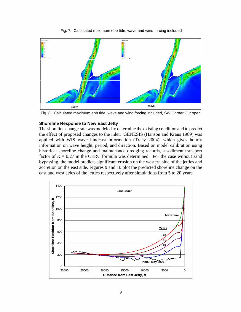
Fig. 7. Calculated maximum ebb tide, wave and wind forcing included
150-ft 200-ft Fig. 8. Calculated maximum ebb tide, wave and wind forcing included, SW Corner Cut open
Shoreline Response to New East Jetty The shoreline change rate was modeled to determine the existing condition and to predict the effect of proposed changes to the inlet. GENESIS (Hanson and Kraus 1989) was applied with WIS wave hindcast information (Tracy 2004), which gives hourly information on wave height, period, and direction. Based on model calibration using historical shoreline change and maintenance dredging records, a sediment transport factor of K = 0.27 in the CERC formula was determined. For the case without sand bypassing, the model predicts significant erosion on the western side of the jetties and accretion on the east side. Figures 9 and 10 plot the predicted shoreline change on the east and west sides of the jetties respectively after simulations from 5 to 20 years.
0
200
400
600
800
1000
1200
1400
050001000015000200002500030000Distance from East Jetty, ft
Shor
elin
e Po
sitio
n fr
om B
asel
ine,
ft
Initial, May 2006
20
5
1015
East Beach
Maximum
Years

10
Fig. 9. Predicted shoreline change east of the MCR
0
200
400
600
800
1000
0 5000 10000 15000 20000 25000Distance from West Jetty, ft
Shor
elin
e Po
sitio
n fr
om B
asel
ine,
ft
Initial, May 2006
20
5 10 15
West Beach
Years
Fig. 10. Predicted shoreline change west of the MCR
Shoreline change also was also simulated including mechanical bypassing (dredging) of the up-drift accretion fillet at the east jetty. A volume of 306,000 m3 (400,000 cy) was bypassed every 2 years and placed on the down-drift beach. Figure 11 indicates that bypassing is essential to maintain the beach to the west, continuing Galveston District practice, and not allowing a large fillet to form on the east, which would more readily allow littoral material to shoal in the entrance channel from the east beach.
Proposed East JettyNo BypassingNo Bypassing
Bypassing
Bypassing
Fig. 11. Shoreline position after 20 years with the proposed jetty design, with and without
sediment bypassing from up-drift to down-drift beaches (photograph May 2006)

11
Review of New East Jetty Concept Inlet process modeling and shoreline change and sediment transport simulations indicate that the most feasible option for decreasing maintenance dredging requirements is construction of a new east jetty. The new east jetty would be similar to the existing west jetty. The primary difference in design is the proposed crest elevation of the landward section of the new jetty. Elevating the landward section of the jetty would reduce sediment infilling of the navigation channel due to wind-blown transport, swash zone transport, and washover during storms. Observation of the sediment training structure (Fig. 4) reveals the extent to which transport over the dry beach can occur. The local-scale circulation and transport models are being applied to compare various designs for the new jetty and navigation channel. They indicate where and to what extent erosion and accretion are likely to occur. Shoreline change modeling indicates it essential that bypassing of sediment around the entrance be continued. Lessons Learned at Other Jetties on the Texas Coast Jetty design and construction technique can reduce initial construction cost of the proposed east jetty and reduce channel maintenance cost as well. There are nine jettied inlets on the Texas Gulf Coast, the earliest of which were constructed in the late 19th century. A review of these jetties by Sargent and Bottin (1989) provides insight on potential construction pitfalls to avoid in consideration of possible jetty modification or construction at the MCR. Most of the jetties were constructed with block-shaped granite cover stone. The shape of the cover stone increases hydraulic stability, but it makes placement difficult for side slopes steeper than about 3H:1V, especially in shallow water, therefore increasing construction cost for steep sides. For land-based construction, jetty crest width should be at least 4.7 m (16 ft) to provide adequate room for maneuvering and operation of construction equipment. Although narrower cross sections are possible, they generally increase construction time and cost. Another consideration for land-based construction is the scour hole that tends to form as the jetty construction progresses offshore. The scour hole migrates with the end of the jetty as it is built seaward. Bedding stone is used to fill the scour hole, often resulting in rock overruns and increasing cost. A potential method to reduce such overruns is to use stone filled mattresses (Hughes 2006) instead of loose bedding stone. Finally, providing adequate elevation on the landward side of the jetty will reduce or eliminate bypassing of its landward side by wind-blown and swash zone sediment transport. CONCLUDING DISCUSSION A long-term plan for reducing maintenance dredging cost and increasing navigation channel reliability at the MCR is under development. The study entails examination of inlet processes and coastal processes, and modification of existing and construction of new structures. Numerical analysis has shown that a new east jetty without a weir and located closer to the original west jetty than the existing design should reduce the dredging interval by increasing channel hydraulic efficiency. A long-term bypassing plan will ensure that the MCR navigation project will not cause erosion of the down-drift beach.

12
ACKNOWLEDGEMENTS This study was supported by the U.S. Army Engineer District, Galveston. Permission was granted by Headquarters, U.S. Army Corps of Engineers, to publish this information. REFERENCES Brown, M.E., Kieslich, J.M., and Kraus, N.C. (2003). “Regional circulation modeling
of the Texas Coast and inland coastal waters,” Proc. 8th International Conf. on Estuarine and Coastal Modeling, ASCE, 192-214.
Hanson, H., and Kraus, N.C. (1989). “GENESIS: Generalized model for simulating shoreline change. Report 1: Technical reference,” TR CERC-89-19, U.S. Army Engineer Waterways Experiment Station, Coastal Engineering Research Center, Vicksburg, MS.
Heilman, D.J., and Edge, B.L. (1996). “Interaction of the Colorado River Project, Texas, with longshore sediment transport,” Proc. 25th Coastal Eng. Conf., ASCE, 3,309-3,322.
Hughes, S.A. (2006). “Uses for marine mattresses in coastal engineering,” CHETN – III-72, U.S. Army Engineer Research and Development Center, Vicksburg, MS.
King, D.B., and Prickett, T.L. (1998). “Mouth of the Colorado River, Texas, monitoring program,” Monitoring Completed Navigation Projects Program. TR CHL-98-2, U.S. Army Corps of Engineers, Waterways Experiment Station, Vicksburg, MS.
Kraus, N.C. (2007). “Inlets along the Texas coast, USA,” Proc. Coastal Sediments ’07, ASCE, in press.
Kraus, N.C., Lin, L., and Barcak, R.G. (2004). “Alternatives to reduce channel shoaling, Mouth of Colorado River Navigation Channel, Texas,” Proc. Dredging 02, ASCE, CD ROM, 13 pp.
Kraus, N. C., and Militello, A. (1999). “Hydraulic study of multiple inlet system: East Matagorda Bay, Texas,” J. Hydraul. Res., 125(3), 224-232.
Lin, L., Kraus, N.C., and Barcak, R.G. (2001). “Predicting hydrodynamics of a proposed multiple-inlet system, Colorado River, Texas,” Proc. 7th International Conf. on Estuarine and Coastal Modeling, ASCE, 837-851.
Lin, L., Kraus, N.C., and Barcak, R.G. (2003). “'Modeling coastal sediment transport at the Mouth of the Colorado River, Texas,” Proc. 8th International Estuarine and Coastal Modeling Conf., ASCE, 988-1006.
Lin, L., Mase, H., Yamada, F., and Demirbilek, Z. (2006). “Wave-Action Balance Equation Diffraction (WABED) model, Part 1: Tests of wave diffraction and reflection at inlets,” Coastal and Hydraulic Engineering Technical Note ERDC/CHL CHETN-III-73, U.S. Army Engineer Research and Development Center.
Militello, A., Reed, C. W., Zundel, A. K., and Kraus, N. C. (2004). “Two-dimensional depth-averaged circulation model M2D: Version 2.0, Report 1: Documentation and user’s guide,” ERDC/CHL TR-04-02, U.S. Army Engineer Research and Development Center, Vicksburg, MS.

13
Sargent, F., and Bottin, R. (1989). “Case histories of Corps breakwaters and jetty structures,” REMR Report 9 Southwestern Division. January 1989, U.S. Army Corps of Engineers, Washington, D.C.
Shore Protection Manual (SPM) (1984). 4th ed., 2 Vol, U.S. Army Engineer Waterways Experiment Station, U.S. Govt. Printing Office, Washington, DC.
Tracy, B.A. (2004). “Wave Information Studies: Hindcast wave data for U.S. coasts,” U.S. Army Engineer Research and Development Center, Vicksburg, MS. http://frf.usace.army.mil/cgi-bin/wis/atl/atl_main.html.
USACE (1977). “Mouth of Colorado River, Texas, Phase 1,” General Design Memorandum (navigation features),” U.S. Army Engineer District, Galveston, TX.
USACE. (1992). “Inlets along the Texas Gulf Coast,” Section 22 Report, Planning Assistance to the States Program, U.S. Army Engineer District, Galveston, TX.