BANSHEE - Design N' Construction · The Banshee must be installed with a primary siren that is...
12
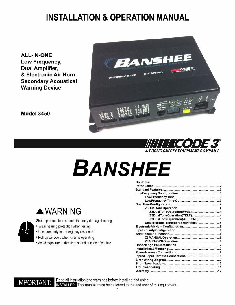
1 Contents: Introduction.............................................................................2 Standard Features...................................................................2 Low Frequency Configuration.................................................3 Low Frequency Tone.....................................................3 Low Frequency Time-Out..............................................3 Dual Tone Configuration..........................................................4 Z3 Dual Tone Operation..................................................4 Z3 Dual Tone Operation (WAIL).................................4 Z3 Dual Tone Operation (YELP).................................4 Z3 Dual Tone Operation (ALT TONE).........................5 Universal Dual Tone (non-Z3 systems)..........................5 Electronic Air Horn Configuration...........................................5 Input Polarity Configuration....................................................6 Additional Z3 Functions...........................................................6 Z3 MANUAL Operation..................................................6 Z3AIR HORN Operation.................................................6 Unpacking & Pre-installation...................................................7 Installation & Mounting............................................................7 Power Harness Connections...................................................8 Input/Output Harness Connections........................................8 Siren Wiring Diagram...............................................................9 Siren Specifications..............................................................10 Troubleshooting....................................................................11 Warranty .................................................................................12 WARNING Sirens produce loud sounds that may damage hearing • Wear hearing protection when testing • Use siren only for emergency response • Roll up windows when siren is operating • Avoid exposure to the siren sound outside of vehicle Read all instruction and warnings before installing and using. INSTALLER: This manual must be delivered to the end user of this equipment. IMPORTANT: INSTALLATION & OPERATION MANUAL ALL-IN-ONE Low Frequency, Dual Amplifier, & Electronic Air Horn Secondary Acoustical Warning Device Model 3450 BANSHEE
Transcript of BANSHEE - Design N' Construction · The Banshee must be installed with a primary siren that is...
1
Contents:Introduction.............................................................................2Standard Features...................................................................2Low Frequency Configuration.................................................3
Low Frequency Tone.....................................................3Low Frequency Time-Out..............................................3
Dual Tone Configuration..........................................................4Z3 Dual Tone Operation..................................................4
Z3 Dual Tone Operation (WAIL).................................4Z3 Dual Tone Operation (YELP).................................4Z3 Dual Tone Operation (ALT TONE).........................5
Universal Dual Tone (non-Z3 systems)..........................5Electronic Air Horn Configuration...........................................5Input Polarity Configuration....................................................6Additional Z3 Functions...........................................................6
Z3 MANUAL Operation..................................................6Z3 AIR HORN Operation.................................................6
Unpacking & Pre-installation...................................................7Installation & Mounting............................................................7Power Harness Connections...................................................8Input/Output Harness Connections........................................8Siren Wiring Diagram...............................................................9 Siren Specifications..............................................................10Troubleshooting....................................................................11Warranty.................................................................................12
WARNINGSirens produce loud sounds that may damage hearing• Wear hearing protection when testing• Use siren only for emergency response• Roll up windows when siren is operating• Avoid exposure to the siren sound outside of vehicle
Read all instruction and warnings before installing and using.INSTALLER: This manual must be delivered to the end user of this equipment.IMPORTANT:
INSTALLATION & OPERATION MANUAL
ALL-IN-ONELow Frequency,Dual Amplifier,& Electronic Air HornSecondary Acoustical Warning Device
Model 3450
BANSHEE
2
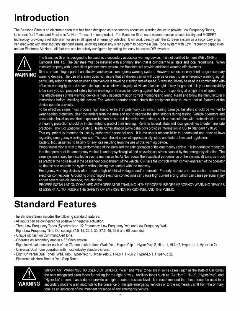
!The Banshee Siren is designed to be used as a secondary acoustical warning device. It is not certified to meet SAE J1849 orCalifornia Title 13. The Banshee must be installed with a primary siren that is compliant to all state and local regulations. When installed properly with a compliant primary siren system, the Banshee will provide additional warning effectiveness.Sirens are an integral part of an effective audio/visual emergency warning system. However, sirens are only short range secondary warning devices. The use of a siren does not insure that all drivers can or will observe or react to an emergency warning signal, particularly at long distances or when either vehicle is traveling at a high rate of speed. Sirens should only be used in a combination with effective warning lights and never relied upon as a sole warning signal. Never take the right of way for granted. It is your responsibility to be sure you can proceed safely before entering an intersection driving against traffic, or responding at a high rate of speed.The effectiveness of this warning device is highly dependent upon correct mounting and wiring. Read and follow the manufacturer’s instructions before installing this device. The vehicle operator should check the equipment daily to insure that all features of the device operate correctly. To be effective, sirens must produce high sound levels that potentially can inflict hearing damage. Installers should be warned to wear hearing protection, clear bystanders from the area and not to operate the siren indoors during testing. Vehicle operators and occupants should assess their exposure to siren noise and determine what steps, such as consultation with professionals or use of hearing protection should be implemented to protect their hearing. Refer to federal, state and local guidelines to determine safe practices. The Occupational Safety & Health Administration (www.osha.gov) provides information in OSHA Standard 1910.95.This equipment is intended for use by authorized personnel only. It is the user’s responsibility to understand and obey all laws regarding emergency warning devices. The user should check all applicable city, state and federal laws and regulations.Code 3, Inc., assumes no liability for any loss resulting from the use of this warning device.Proper installation is vital to the performance of the siren and the safe operation of the emergency vehicle. It is important to recognize that the operator of the emergency vehicle is under psychological and physiological stress caused by the emergency situation. The siren system should be installed in such a manner as to: A) Not reduce the acoustical performance of the system, B) Limit as much as practical the noise level in the passenger compartment of the vehicle, C) Place the controls within convenient reach of the operator so that he can operate the system without losing eye contact with the roadway. Emergency warning devices often require high electrical voltages and/or currents. Properly protect and use caution around live electrical connections. Grounding or shorting of electrical connections can cause high current arcing, which can cause personal injury and/or severe vehicle damage, including fire. PROPER INSTALLATION COMBINED WITH OPERATOR TRAINING IN THE PROPER USE OF EMERGENCY WARNING DEVICES IS ESSENTIAL TO INSURE THE SAFETY OF EMERGENCY PERSONNEL AND THE PUBLIC.
WARNING
Standard FeaturesThe Banshee Siren includes the following standard features:- All inputs can be configured for positive or negative activation.- Three Low Frequency Tones (Synchronized 1/2 Frequency, Low Frequency Yelp and Low Frequency Wail).- Eight Low Frequency Time Out settings (7.5, 15, 22.5, 30, 37.5, 45, 52.5 and 60 seconds).- Unique old fashion CommandAlert tone.- Operates as secondary amp in a Z3 Siren system.- Eight individual tones for each of the Z3 tone push-buttons (Wail, Yelp, Hyper-Yelp 1, Hyper-Yelp 2, Hi-Lo 1, Hi-Lo 2, Hyper-Lo 1, Hyper-Lo 2).- Universal Dual Tone operation with most industry standard sirens.- Eight Universal Dual Tones (Wail, Yelp, Hyper-Yelp 1, Hyper-Yelp 2, Hi-Lo 1, Hi-Lo 2, Hyper-Lo 1, Hyper-Lo 2).- Electronic Air Horn Tone or Yelp Stop Tone.
IntroductionThe Banshee Siren is an electronic siren that has been designed as a secondary acoustical warning device to provide Low Frequency Tones,Universal Dual Tones and Electronic Air Horn Tones all in one product. The Banshee Siren uses microprocessor based circuitry and MOSFET technology providing a reliable siren for use in all types of emergency vehicles. It will work directly with the Z3 Siren system as a secondary amp. It can also work with most industry standard sirens, allowing almost any siren system to become a Dual Tone system with Low Frequency capabilities and an Electronic Air Horn. All features can be quickly configured by setting the easy to access DIP switches.
! IMPORTANT WARNINGS TO USERS OF SIRENS: “Wail” and “Yelp” tones are in some cases (such as the state of California) the only recognized siren tones for calling for the right of way. Ancillary tones such as “Air Horn”, “Hi-Lo”, “Hyper-Yelp”, and “Hyper-Lo” in some cases do not provide as high a sound pressure level. It is recommended that these tones be used in a secondary mode to alert motorists to the presence of multiple emergency vehicles or to the momentary shift from the primary tone as an indication of the imminent presence of any emergency vehicle.
WARNING
3
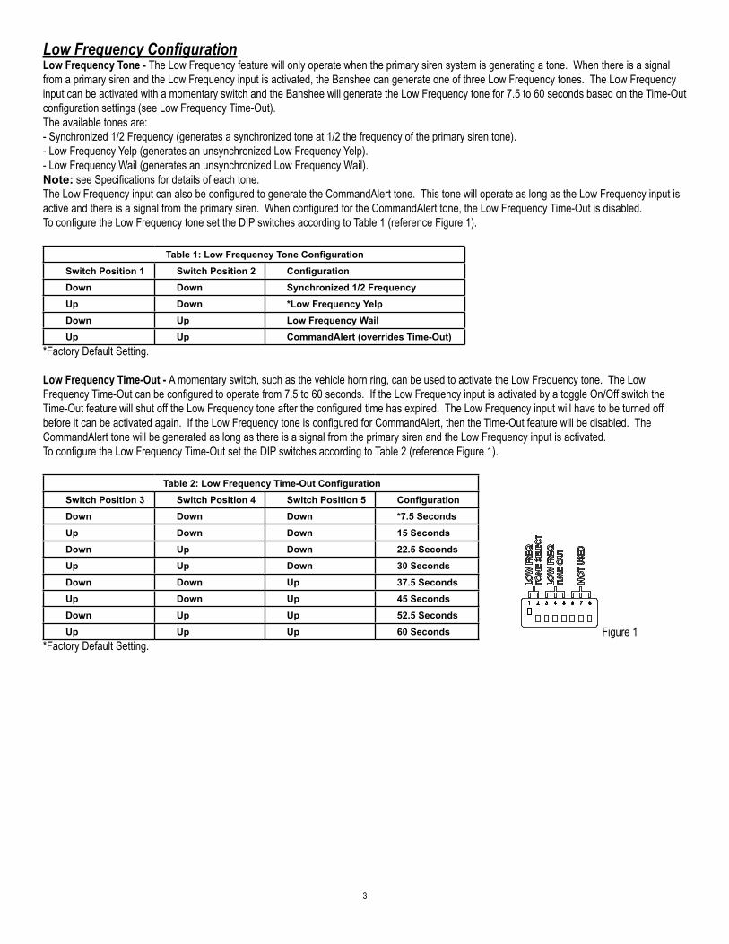
Low Frequency ConfigurationLow Frequency Tone - The Low Frequency feature will only operate when the primary siren system is generating a tone. When there is a signal from a primary siren and the Low Frequency input is activated, the Banshee can generate one of three Low Frequency tones. The Low Frequency input can be activated with a momentary switch and the Banshee will generate the Low Frequency tone for 7.5 to 60 seconds based on the Time-Out configuration settings (see Low Frequency Time-Out).The available tones are:- Synchronized 1/2 Frequency (generates a synchronized tone at 1/2 the frequency of the primary siren tone).- Low Frequency Yelp (generates an unsynchronized Low Frequency Yelp).- Low Frequency Wail (generates an unsynchronized Low Frequency Wail).Note: see Specifications for details of each tone.The Low Frequency input can also be configured to generate the CommandAlert tone. This tone will operate as long as the Low Frequency input is active and there is a signal from the primary siren. When configured for the CommandAlert tone, the Low Frequency Time-Out is disabled.To configure the Low Frequency tone set the DIP switches according to Table 1 (reference Figure 1).
Table 1: Low Frequency Tone ConfigurationSwitch Position 1 Switch Position 2 ConfigurationDown Down Synchronized 1/2 FrequencyUp Down *Low Frequency YelpDown Up Low Frequency WailUp Up CommandAlert (overrides Time-Out)
*Factory Default Setting.
Low Frequency Time-Out - A momentary switch, such as the vehicle horn ring, can be used to activate the Low Frequency tone. The Low Frequency Time-Out can be configured to operate from 7.5 to 60 seconds. If the Low Frequency input is activated by a toggle On/Off switch the Time-Out feature will shut off the Low Frequency tone after the configured time has expired. The Low Frequency input will have to be turned off before it can be activated again. If the Low Frequency tone is configured for CommandAlert, then the Time-Out feature will be disabled. The CommandAlert tone will be generated as long as there is a signal from the primary siren and the Low Frequency input is activated.To configure the Low Frequency Time-Out set the DIP switches according to Table 2 (reference Figure 1).
Table 2: Low Frequency Time-Out ConfigurationSwitch Position 3 Switch Position 4 Switch Position 5 ConfigurationDown Down Down *7.5 SecondsUp Down Down 15 SecondsDown Up Down 22.5 SecondsUp Up Down 30 SecondsDown Down Up 37.5 SecondsUp Down Up 45 SecondsDown Up Up 52.5 SecondsUp Up Up 60 Seconds
*Factory Default Setting.Figure 1
4
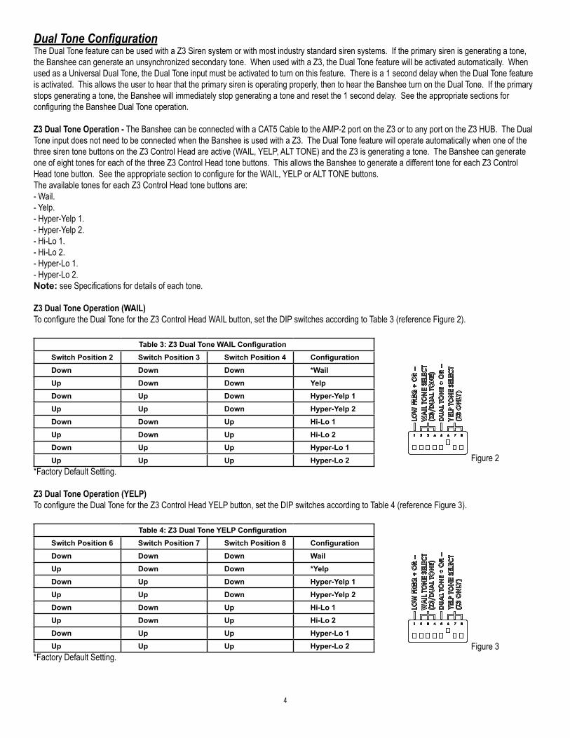
Dual Tone ConfigurationThe Dual Tone feature can be used with a Z3 Siren system or with most industry standard siren systems. If the primary siren is generating a tone, the Banshee can generate an unsynchronized secondary tone. When used with a Z3, the Dual Tone feature will be activated automatically. When used as a Universal Dual Tone, the Dual Tone input must be activated to turn on this feature. There is a 1 second delay when the Dual Tone feature is activated. This allows the user to hear that the primary siren is operating properly, then to hear the Banshee turn on the Dual Tone. If the primary stops generating a tone, the Banshee will immediately stop generating a tone and reset the 1 second delay. See the appropriate sections for configuring the Banshee Dual Tone operation.
Z3 Dual Tone Operation - The Banshee can be connected with a CAT5 Cable to the AMP-2 port on the Z3 or to any port on the Z3 HUB. The Dual Tone input does not need to be connected when the Banshee is used with a Z3. The Dual Tone feature will operate automatically when one of the three siren tone buttons on the Z3 Control Head are active (WAIL, YELP, ALT TONE) and the Z3 is generating a tone. The Banshee can generate one of eight tones for each of the three Z3 Control Head tone buttons. This allows the Banshee to generate a different tone for each Z3 Control Head tone button. See the appropriate section to configure for the WAIL, YELP or ALT TONE buttons.The available tones for each Z3 Control Head tone buttons are:- Wail.- Yelp.- Hyper-Yelp 1.- Hyper-Yelp 2.- Hi-Lo 1.- Hi-Lo 2.- Hyper-Lo 1.- Hyper-Lo 2.Note: see Specifications for details of each tone.
Z3 Dual Tone Operation (WAIL)To configure the Dual Tone for the Z3 Control Head WAIL button, set the DIP switches according to Table 3 (reference Figure 2).
Table 3: Z3 Dual Tone WAIL ConfigurationSwitch Position 2 Switch Position 3 Switch Position 4 ConfigurationDown Down Down *WailUp Down Down YelpDown Up Down Hyper-Yelp 1Up Up Down Hyper-Yelp 2Down Down Up Hi-Lo 1Up Down Up Hi-Lo 2Down Up Up Hyper-Lo 1Up Up Up Hyper-Lo 2
*Factory Default Setting.
Z3 Dual Tone Operation (YELP)To configure the Dual Tone for the Z3 Control Head YELP button, set the DIP switches according to Table 4 (reference Figure 3).
Table 4: Z3 Dual Tone YELP ConfigurationSwitch Position 6 Switch Position 7 Switch Position 8 ConfigurationDown Down Down WailUp Down Down *YelpDown Up Down Hyper-Yelp 1Up Up Down Hyper-Yelp 2Down Down Up Hi-Lo 1Up Down Up Hi-Lo 2Down Up Up Hyper-Lo 1Up Up Up Hyper-Lo 2
*Factory Default Setting.
Figure 2
Figure 3
5
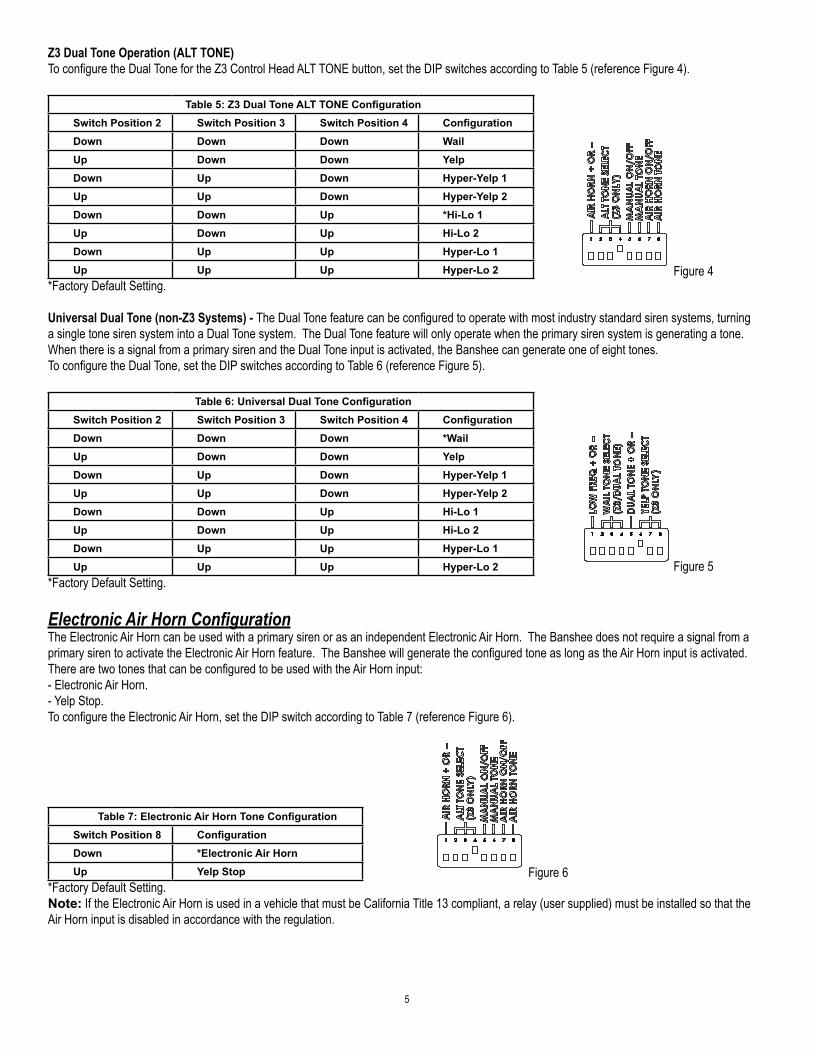
Z3 Dual Tone Operation (ALT TONE)To configure the Dual Tone for the Z3 Control Head ALT TONE button, set the DIP switches according to Table 5 (reference Figure 4).
Table 5: Z3 Dual Tone ALT TONE ConfigurationSwitch Position 2 Switch Position 3 Switch Position 4 ConfigurationDown Down Down WailUp Down Down YelpDown Up Down Hyper-Yelp 1Up Up Down Hyper-Yelp 2Down Down Up *Hi-Lo 1Up Down Up Hi-Lo 2Down Up Up Hyper-Lo 1Up Up Up Hyper-Lo 2
*Factory Default Setting.
Universal Dual Tone (non-Z3 Systems) - The Dual Tone feature can be configured to operate with most industry standard siren systems, turning a single tone siren system into a Dual Tone system. The Dual Tone feature will only operate when the primary siren system is generating a tone. When there is a signal from a primary siren and the Dual Tone input is activated, the Banshee can generate one of eight tones.To configure the Dual Tone, set the DIP switches according to Table 6 (reference Figure 5).
Table 6: Universal Dual Tone ConfigurationSwitch Position 2 Switch Position 3 Switch Position 4 ConfigurationDown Down Down *WailUp Down Down YelpDown Up Down Hyper-Yelp 1Up Up Down Hyper-Yelp 2Down Down Up Hi-Lo 1Up Down Up Hi-Lo 2Down Up Up Hyper-Lo 1Up Up Up Hyper-Lo 2
*Factory Default Setting.
Electronic Air Horn ConfigurationThe Electronic Air Horn can be used with a primary siren or as an independent Electronic Air Horn. The Banshee does not require a signal from a primary siren to activate the Electronic Air Horn feature. The Banshee will generate the configured tone as long as the Air Horn input is activated.There are two tones that can be configured to be used with the Air Horn input:- Electronic Air Horn.- Yelp Stop.To configure the Electronic Air Horn, set the DIP switch according to Table 7 (reference Figure 6).
Table 7: Electronic Air Horn Tone ConfigurationSwitch Position 8 ConfigurationDown *Electronic Air HornUp Yelp Stop
*Factory Default Setting.Note: If the Electronic Air Horn is used in a vehicle that must be California Title 13 compliant, a relay (user supplied) must be installed so that the Air Horn input is disabled in accordance with the regulation.
Figure 4
Figure 5
Figure 6
6
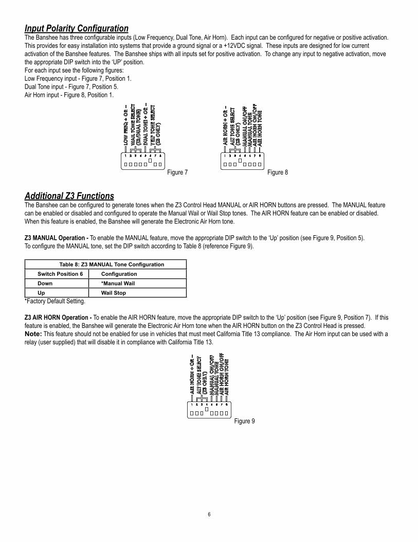
Input Polarity ConfigurationThe Banshee has three configurable inputs (Low Frequency, Dual Tone, Air Horn). Each input can be configured for negative or positive activation. This provides for easy installation into systems that provide a ground signal or a +12VDC signal. These inputs are designed for low current activation of the Banshee features. The Banshee ships with all inputs set for positive activation. To change any input to negative activation, move the appropriate DIP switch into the ‘UP’ position.For each input see the following figures:Low Frequency input - Figure 7, Position 1.Dual Tone input - Figure 7, Position 5.Air Horn input - Figure 8, Position 1.
Additional Z3 FunctionsThe Banshee can be configured to generate tones when the Z3 Control Head MANUAL or AIR HORN buttons are pressed. The MANUAL feature can be enabled or disabled and configured to operate the Manual Wail or Wail Stop tones. The AIR HORN feature can be enabled or disabled. When this feature is enabled, the Banshee will generate the Electronic Air Horn tone.
Z3 MANUAL Operation - To enable the MANUAL feature, move the appropriate DIP switch to the ‘Up’ position (see Figure 9, Position 5).To configure the MANUAL tone, set the DIP switch according to Table 8 (reference Figure 9).
Table 8: Z3 MANUAL Tone ConfigurationSwitch Position 6 ConfigurationDown *Manual WailUp Wail Stop
*Factory Default Setting.
Z3 AIR HORN Operation - To enable the AIR HORN feature, move the appropriate DIP switch to the ‘Up’ position (see Figure 9, Position 7). If this feature is enabled, the Banshee will generate the Electronic Air Horn tone when the AIR HORN button on the Z3 Control Head is pressed.Note: This feature should not be enabled for use in vehicles that must meet California Title 13 compliance. The Air Horn input can be used with a relay (user supplied) that will disable it in compliance with California Title 13.
Figure 7 Figure 8
Figure 9
7
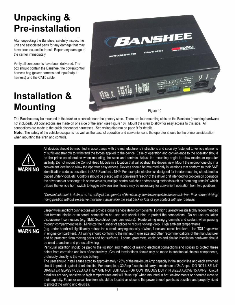
Unpacking & Pre-installationAfter unpacking the Banshee, carefully inspect the unit and associated parts for any damage that may have been caused in transit. Report any damage to the carrier immediately.
Verify all components have been delivered. The box should contain the Banshee, the power/control harness bag (power harness and input/output harness) and the CAT5 cable.
Installation & Mounting
!All devices should be mounted in accordance with the manufacturer’s instructions and securely fastened to vehicle elements of sufficient strength to withstand the forces applied to the device. Ease of operation and convenience to the operator should be the prime consideration when mounting the siren and controls. Adjust the mounting angle to allow maximum operator visibility. Do not mount the Control Head Module in a location that will obstruct the drivers view. Mount the microphone clip in a convenient location to allow the operator easy access. Devices should be mounted only in locations that conform to their SAE identification code as described in SAE Standard J1849. For example, electronics designed for interior mounting should not be placed under-hood, etc. Controls should be placed within convenient reach* of the driver or if intended for two person operation the driver and/or passenger. In some vehicles, multiple control switches and/or using methods such as “horn ring transfer” which utilizes the vehicle horn switch to toggle between siren tones may be necessary for convenient operation from two positions.
*Convenient reach is defined as the ability of the operator of the siren system to manipulate the controls from their normal driving/riding position without excessive movement away from the seat back or loss of eye contact with the roadway.
WARNING
The Banshee may be mounted in the trunk or a console near the primary siren. There are four mounting slots on the Banshee (mounting hardware not included). All connections are made on one side of the siren (see Figure 10). Mount the siren to allow for easy access to this side. All connections are made to the quick disconnect harnesses. See wiring diagram on page 9 for details.Note: The safety of the vehicle occupants as well as the ease of operation and convenience to the operator should be the prime consideration when mounting the siren and controls.
Figure 10
!Larger wires and tight connections will provide longer service life for components. For high current wires it is highly recommended that terminal blocks or soldered connections be used with shrink tubing to protect the connections. Do not use insulation displacement connectors (e.g. 3M® Scotchlock type connectors). Route wiring using grommets and sealant when passing through compartment walls. Minimize the number of splices to reduce voltage drop. High ambient temperatures(e.g. under-hood) will significantly reduce the current carrying capacity of wires, fuses and circuit breakers. Use “SXL” type wire in engine compartment. All wiring should conform to the minimum wire size and other recommendations of the manufacturer and be protected from moving parts and hot surfaces. Looms, grommets, cable ties and similar installation hardware should be used to anchor and protect all wiring.Particular attention should be paid to the location and method of making electrical connections and splices to protect these points from corrosion and loss of conductivity. Ground terminations should only be made to substantial chassis components, preferably directly to the vehicle battery.The user should install a fuse sized to approximately 125% of the maximum Amp capacity in the supply line and each switched circuit to protect against short circuits. For example, a 30 Amp fuse should carry a maximum of 24 Amps. DO NOT USE 1/4” DIAMETER GLASS FUSES AS THEY ARE NOT SUITABLE FOR CONTINUOUS DUTY IN SIZES ABOVE 15 AMPS. Circuit breakers are very sensitive to high temperatures and will “false trip” when mounted in hot environments or operated close to their capacity. Fuses or circuit breakers should be located as close to the power takeoff points as possible and properly sized to protect the wiring and devices.
WARNING

8
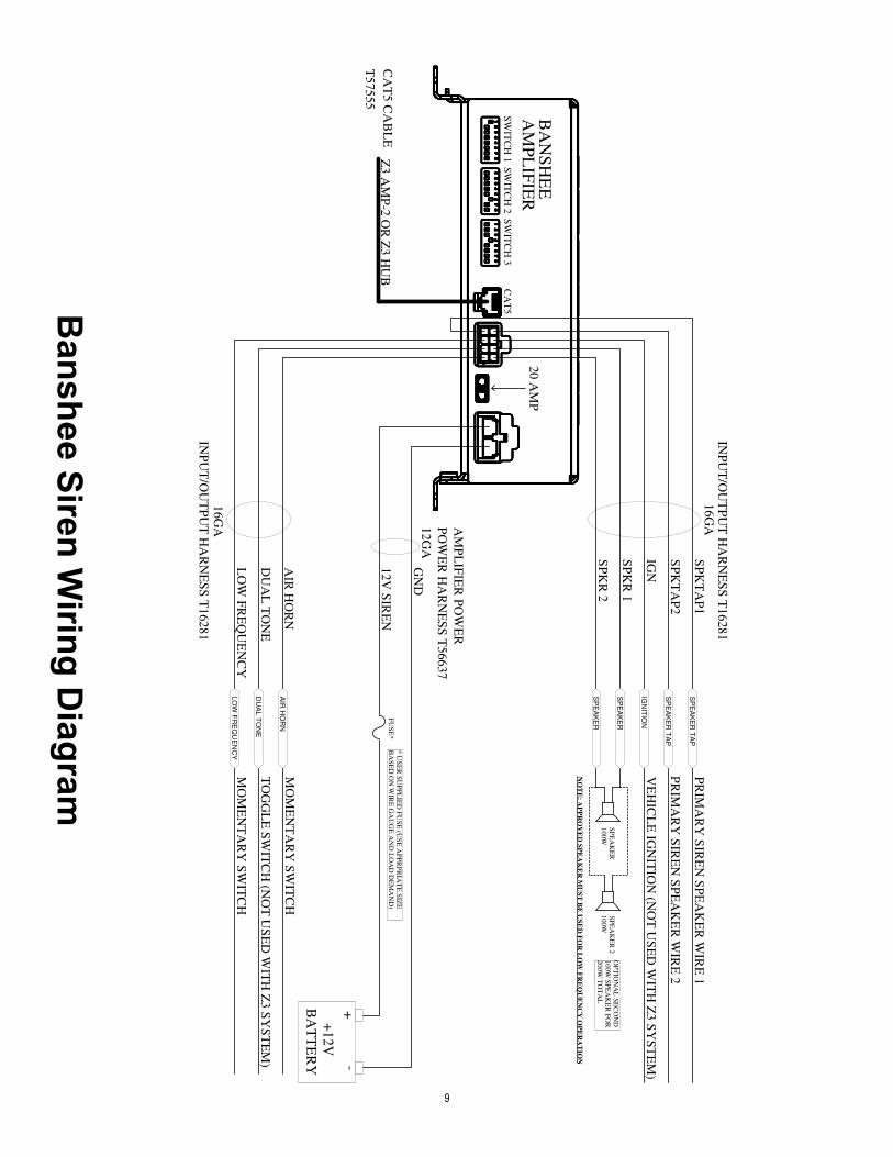
Power Harness ConnectionsThe Banshee is designed so that the main Power Harness can be connected to the vehicle battery at all times. The siren will enter into a low current standby mode when none of the inputs are activated. Connect the BLACK ground wire to the negative terminal of the battery. Use the appropriate wire gauge rated at 125% of the current required to operate the Banshee (see Specifications for current draw). Connect the RED power wire through a fuse to the positive terminal of the battery. Use the appropriate wire gauge and fuse rated at 125% of the current required to operate the Banshee (see Specifications for current draw). The fuse should be located as close as possible to the vehicle battery to protect the wiring.See wiring diagram on page 9 for details.
Input/Output Harness ConnectionsEach wire in the Input/Output Harness is marked to identify the wire function.• The Air Horn input will activate either the Electronic Air Horn tone or the Yelp Stop tone as long as the input is turned on. This input does not
require a signal from the primary siren in order to generate a tone.• The Low Frequency input will activate one of the Low Frequency tones or the CommandAlert tone. The Low Frequency tones will operate for
the time configured by the Time-Out DIP switches. The CommandAlert tone will override the Time-Out configuration and operate as long as the Low Frequency input is turned on.
• The Dual Tone input will activate the configured tone as long as the input is turned on.• The Low Frequency and Dual Tone inputs require a signal from the primary siren in order to operate. If there is no signal from the primary siren
these inputs will not generate any tones.• The three tone inputs work on a priority system. The Air Horn input has the first priority and will override the other two inputs. The Low
Frequency has the second priority and will override the Dual Tone input. The Dual Tone input has the lowest priority.
IGN - Ignition wire. Connect to a +12VDC signal that is active when the vehicle ignition is on. This input will cause the Banshee to leave the low current standby mode when connected to +12VDC. No other inputs will operate until this input is activated.Note: If the Banshee is connected to a Z3 using the CAT5 cable, this wire does not have to be connected. The Banshee will get an ignition signal from the Z3.
LOWFREQ - Low Frequency input. Connect to a momentary switch (e.g., Vehicle Horn Ring). Make sure the DIP switch is set to match the switch polarity. This input will cause the Banshee to generate the configured Low Frequency tone. Connect to a toggle On/Off switch if the Low Frequency input is configured for the CommandAlert tone.
D-TONE - Dual Tone input. Connect to a toggle On/Off switch. Make sure the DIP switch is set to match the switch polarity. This input will cause the Banshee to generate the configured Dual Tone as long as the toggle switch is in the ‘On’ position.Note: If the Banshee is connected to a Z3 using the CAT5 cable, this wire does not have to be connected. The Z3 will send commands to automatically activate the Dual Tone mode.
AIRHORN - Electronic Air Horn input. Connect to a momentary switch (e.g., Remote Foot Switch). Make sure DIP switch is set to match the switch polarity. This input will cause the Banshee to generate the configured Air Horn tone.
SPKTAP1 - Speaker Tap 1 input. Connect to terminal one of the primary siren speaker output.SPKTAP2 - Speaker Tap 2 input. Connect to terminal two of the primary siren speaker output.Note: The Speaker Tap wires are used to monitor the primary siren tone signal. Failure to connect these wires will disable the Low Frequency and Dual Tone modes.
SPKR 1 - Speaker 1 output. Connect to terminal one on the Banshee speaker.SPKR 2 - Speaker 2 output. Connect to terminal two on the Banshee speaker.The Banshee is designed to operate a single 100W speaker or two 100W speakers connected in parallel.Note: If the Banshee will be used to generate Low Frequency tones, a Code 3® approved speaker must be used. Using a non-approved speaker may reduce performance or possibly damage the speaker. See wiring diagram on page 9 for details.
9
Banshee Siren W
iring Diagram
BA
NS
HE
E
12V
SIR
EN
GN
D
20 A
MP
AIR
HO
RN
DU
AL
TO
NE
LO
W F
RE
QU
EN
CY
SP
KR
2
SP
KR
1
IGN
12G
A
PO
WE
R H
AR
NE
SS
T56637
FU
SE
*
100W
SP
EA
KE
R
AIR
HO
RN
DU
AL T
ON
E
SP
EA
KE
R T
AP
SP
EA
KE
R
LO
W F
RE
QU
EN
CY
SP
EA
KE
R T
AP
IGN
ITIO
N
SP
EA
KE
R
AM
PL
IFIE
R
Z3 A
MP
-2 O
R Z
3 H
UB
CA
T5 C
AB
LE
SW
ITC
H 1
SW
ITC
H 2
SW
ITC
H 3
CA
T5
SP
KT
AP
2
SP
KT
AP
116G
AIN
PU
T/O
UT
PU
T H
AR
NE
SS
T16281
16G
A
INP
UT
/OU
TP
UT
HA
RN
ES
S T
16281
PR
IMA
RY
SIR
EN
SP
EA
KE
R W
IRE
2
PR
IMA
RY
SIR
EN
SP
EA
KE
R W
IRE
1
MO
ME
NT
AR
Y S
WIT
CH
NO
TE
: AP
PR
OV
ED
SP
EA
KE
R M
US
T B
E U
SE
D F
OR
LO
W F
RE
QU
EN
CY
OP
ER
AT
ION
MO
ME
NT
AR
Y S
WIT
CH
T57555
100W
SP
EA
KE
R 2
OP
TIO
NA
L S
EC
ON
D
100W
SP
EA
KE
R F
OR
200W
TO
TA
L
SY
ST
EM
* U
SE
R S
UP
PL
IED
FU
SE
(US
E A
PP
RP
RIA
TE
SIZ
E
BA
SE
D O
N W
IRE
GA
UG
E A
ND
LO
AD
DE
MA
ND
)
VE
HIC
LE
IGN
ITIO
N (N
OT
US
ED
WIT
H Z
3 S
YS
TE
M)
TO
GG
LE
SW
ITC
H (N
OT
US
ED
WIT
H Z
3 S
YS
TE
M)
+-
BA
TT
ER
Y
+1
2V
AM
PL
IFIE
R P
OW
ER
10
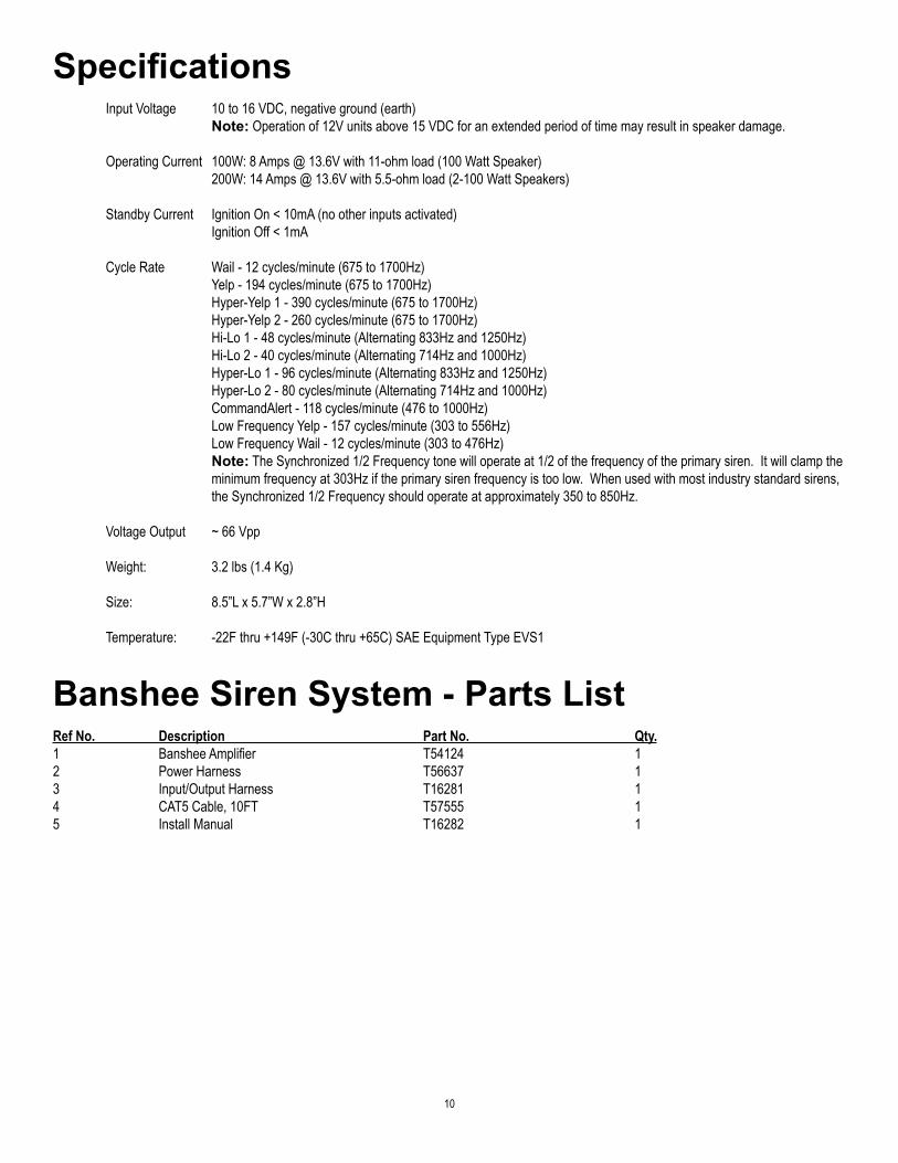
Specifications Input Voltage 10 to 16 VDC, negative ground (earth) Note: Operation of 12V units above 15 VDC for an extended period of time may result in speaker damage.
Operating Current 100W: 8 Amps @ 13.6V with 11-ohm load (100 Watt Speaker) 200W: 14 Amps @ 13.6V with 5.5-ohm load (2-100 Watt Speakers)
Standby Current Ignition On < 10mA (no other inputs activated) Ignition Off < 1mA
Cycle Rate Wail - 12 cycles/minute (675 to 1700Hz) Yelp - 194 cycles/minute (675 to 1700Hz) Hyper-Yelp 1 - 390 cycles/minute (675 to 1700Hz) Hyper-Yelp 2 - 260 cycles/minute (675 to 1700Hz) Hi-Lo 1 - 48 cycles/minute (Alternating 833Hz and 1250Hz) Hi-Lo 2 - 40 cycles/minute (Alternating 714Hz and 1000Hz) Hyper-Lo 1 - 96 cycles/minute (Alternating 833Hz and 1250Hz) Hyper-Lo 2 - 80 cycles/minute (Alternating 714Hz and 1000Hz) CommandAlert - 118 cycles/minute (476 to 1000Hz) Low Frequency Yelp - 157 cycles/minute (303 to 556Hz) Low Frequency Wail - 12 cycles/minute (303 to 476Hz) Note: The Synchronized 1/2 Frequency tone will operate at 1/2 of the frequency of the primary siren. It will clamp the minimum frequency at 303Hz if the primary siren frequency is too low. When used with most industry standard sirens, the Synchronized 1/2 Frequency should operate at approximately 350 to 850Hz.
Voltage Output ~ 66 Vpp
Weight: 3.2 lbs (1.4 Kg)
Size: 8.5”L x 5.7”W x 2.8”H
Temperature: -22F thru +149F (-30C thru +65C) SAE Equipment Type EVS1
Banshee Siren System - Parts ListRef No. Description Part No. Qty.1 Banshee Amplifier T54124 12 Power Harness T56637 13 Input/Output Harness T16281 14 CAT5 Cable, 10FT T57555 15 Install Manual T16282 1
11
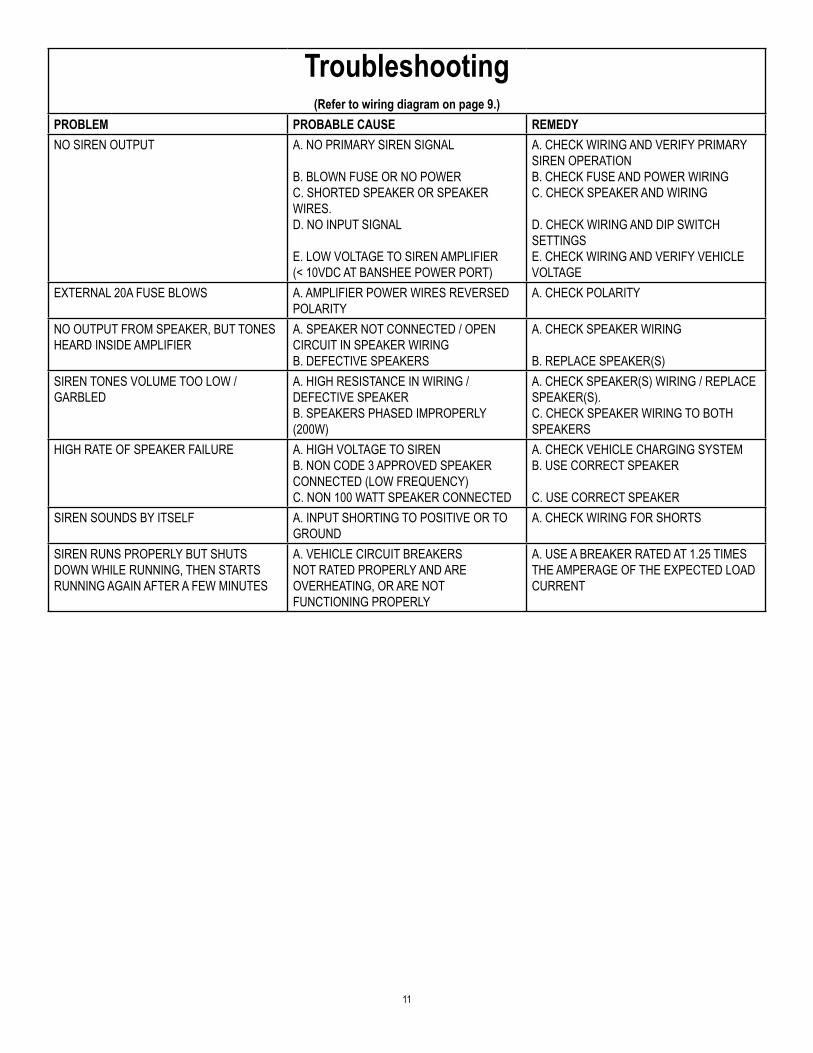
Troubleshooting(Refer to wiring diagram on page 9.)
PROBLEM PROBABLE CAUSE REMEDYNO SIREN OUTPUT A. NO PRIMARY SIREN SIGNAL
B. BLOWN FUSE OR NO POWERC. SHORTED SPEAKER OR SPEAKER WIRES.D. NO INPUT SIGNAL E. LOW VOLTAGE TO SIREN AMPLIFIER(< 10VDC AT BANSHEE POWER PORT)
A. CHECK WIRING AND VERIFY PRIMARY SIREN OPERATIONB. CHECK FUSE AND POWER WIRINGC. CHECK SPEAKER AND WIRING
D. CHECK WIRING AND DIP SWITCH SETTINGS E. CHECK WIRING AND VERIFY VEHICLE VOLTAGE
EXTERNAL 20A FUSE BLOWS A. AMPLIFIER POWER WIRES REVERSED POLARITY
A. CHECK POLARITY
NO OUTPUT FROM SPEAKER, BUT TONES HEARD INSIDE AMPLIFIER
A. SPEAKER NOT CONNECTED / OPEN CIRCUIT IN SPEAKER WIRINGB. DEFECTIVE SPEAKERS
A. CHECK SPEAKER WIRING
B. REPLACE SPEAKER(S)SIREN TONES VOLUME TOO LOW /GARBLED
A. HIGH RESISTANCE IN WIRING /DEFECTIVE SPEAKERB. SPEAKERS PHASED IMPROPERLY (200W)
A. CHECK SPEAKER(S) WIRING / REPLACE SPEAKER(S).C. CHECK SPEAKER WIRING TO BOTH SPEAKERS
HIGH RATE OF SPEAKER FAILURE A. HIGH VOLTAGE TO SIREN B. NON CODE 3 APPROVED SPEAKER CONNECTED (LOW FREQUENCY)C. NON 100 WATT SPEAKER CONNECTED
A. CHECK VEHICLE CHARGING SYSTEMB. USE CORRECT SPEAKER C. USE CORRECT SPEAKER
SIREN SOUNDS BY ITSELF A. INPUT SHORTING TO POSITIVE OR TO GROUND
A. CHECK WIRING FOR SHORTS
SIREN RUNS PROPERLY BUT SHUTS DOWN WHILE RUNNING, THEN STARTS RUNNING AGAIN AFTER A FEW MINUTES
A. VEHICLE CIRCUIT BREAKERS NOT RATED PROPERLY AND ARE OVERHEATING, OR ARE NOT FUNCTIONING PROPERLY
A. USE A BREAKER RATED AT 1.25 TIMES THE AMPERAGE OF THE EXPECTED LOAD CURRENT
12
WARRANTY Code 3®, Inc.’s emergency devices are tested and found to be operational at the time of manufacture. Provided they are installed and operated in accordance with manufacturer’s recommendations, Code 3®, Inc. guarantees all parts and components except the lamps to a period of 1 year, LED Lighthead modules to a period of 5 years (unless otherwise expressed) from the date of purchase or delivery, whichever is later. Units demonstrated to be defective within the warranty period will be repaired or replaced at the factory service center at no cost.
Use of lamp or other electrical load of a wattage higher than installed or recommended by the factory, or use of inappropriate or inadequate wiring or circuit protection causes this warranty to become void. Failure or destruction of the product resulting from abuse or unusual use and/or accidents is not covered by this warranty. Code 3®, Inc. shall in no way be liable for other damages including consequential, indirect or special damages whether loss is due to negligence or breach of warranty.
CODE 3®, INC. MAKES NO OTHER EXPRESS OR IMPLIED WARRANTY INCLUDING, WITHOUT LIMITATION, WARRANTIES OF FITNESS OR MERCHANTABILITY, WITH RESPECT TO THIS PRODUCT.
PRODUCT RETURNSIf a product must be returned for repair or replacement*, please contact our factory to obtain a Return Goods Authorization Number (RGA number) before you ship the product to Code 3®, Inc. Write the RGA number clearly on the package near the mailing label. Be sure you use sufficient packing materials to avoid damage to the product being returned while in transit.
*Code 3®, Inc. reserves the right to repair or replace at its discretion. Code 3®, Inc. assumes no responsibility or liability for expenses incurred for the removal and /or reinstallation of products requiring service and/or repair; nor for the packaging, handling, and shipping: nor for the handling of products returned to sender after the service has been rendered.
Problems or Questions? Call The Technical Assistance HOTLINE - (314) 996-2800
Code 3, Inc.10986 N. Warson Road
St. Louis, Missouri 63114-2029—USAPh. (314) 426-2700 Fax (314) 426-1337
www.code3pse.com
Code 3,® Inc., a subsidiary ofPublic Safety Equipment, Inc.
Revision 0, 02/14 - Instruction Book Part No. T16282©2014 Public Safety Equipment, Inc. Printed in USA
Code 3 is a registered trademark ofCode 3, Inc.