BALLOREX® Dynamic 5.1 Introduction - zenac.com · BROEN BALLOREX® Dynamic is a combined pressure...
11
5.1 BALLOREX® Dynamic 5.1.1 Perfect flow with dynamic balancing BROEN BALLOREX® Dynamic is a combined pressure independent flow limiter and control valve. The new and innovative range of dynamic balancing valves operates independently of changes in system pressure in water-based cooling or heating systems. BROEN BALLOREX® Dynamic can operate either as an automatic flow limiter and control valve or, alternatively without the actuator, simply as an automatic flow limiter. Automatic flow limiter and control valve Installed with an actuator the BROEN BALLOREX® Dynamic combines an automatic flow limiter and a 2-port control valve. With full control authority the valve reacts instantly and adjusts the flow as signalled by the Building Management System (BMS). Since the setting of the valve is done by a horizontal reduction of the inlet area, it has no effect on the vertical stroke length of the actuators. Combined with the built-in pressure regulator this provides a 100% control authority in all situations. Automatic flow limiter Without actuator BROEN BALLOREX® Dynamic is an automatic flow limiter. The designed maximum flow is easily set on the valve. Due to direct flow measuring the valve can be set with a high accuracy of +/- 3%, when using a flow meter. The BROEN BALLOREX® Dynamic ensures that the pre-set flow rate is not exceeded at any point and automatically compensates for pressure fluctuations in the system. 5.1.2 BALLOREX® Dynamic benefits » Direct flow measuring Within an accuracy of +/- 3% the flow through the valve can be directly measured. There is no better way to verify the valve setting and to provide the best in class trouble shooting. This also provides the possibility of optimum pump setting and reduced energy consumption. » Commissioning is no longer needed Just set the valve to the designed flow and hydronic balance is secured. » Automatic balancing Built-in differential pressure regulator corrects for pressure fluctuations in the system and secures constantly regulated flow rates. » Easy valve selection Just select a valve with a flow range that covers the design flow. » Perfect flow control 100% valve authority and full stroke independent of pre-setting for the modulating actuator provides the best chance of delivering good indoor thermal comfort. » Flexible installation The valve can be installed in any position, as long as the flow direction is respected, and can be installed directly onto bends, reducers and flexible hoses. » Different inserts are colour coded Inserts are easily identifiable. 5.1 Introduction
Transcript of BALLOREX® Dynamic 5.1 Introduction - zenac.com · BROEN BALLOREX® Dynamic is a combined pressure...

5.1
BALLOREX® Dynamic
5.1.1 Perfect !ow with dynamic balancingBROEN BALLOREX® Dynamic is a combined pressure independent flow limiter and control valve. The new and innovative range of dynamic balancing valves operates independently of changes in system pressure in water-based cooling or heating systems.
BROEN BALLOREX® Dynamic can operate either as an automatic flow limiter and control valve or, alternatively without the actuator, simply as an automatic flow limiter.
Automatic !ow limiter and control valve
Installed with an actuator the BROEN BALLOREX® Dynamic combines an automatic flow limiter and a 2-port control valve. With full control authority the valve reacts instantly and adjusts the flow as signalled by the Building Management System (BMS). Since the setting of the valve is done by a horizontal reduction of the inlet area, it has no effect on the vertical stroke length of the actuators. Combined with the built-in pressure regulator this provides a 100% control authority in all situations.
Automatic !ow limiter
Without actuator BROEN BALLOREX® Dynamic is an automatic flow limiter. The designed maximum flow is easily set on the valve. Due to direct flow measuring the valve can be set with a high accuracy of +/- 3%, when using a flow meter. The BROEN BALLOREX® Dynamic ensures that the pre-set flow rate is not exceeded at any point and automatically compensates for pressure fluctuations in the system.
5.1.2 BALLOREX® Dynamic bene"ts» Direct flow measuring Within an accuracy of +/- 3% the flow through the valve can be directly measured. There is no better way to verify the valve setting and to provide the best in class trouble shooting. This also provides the possibility of optimum pump setting and reduced energy consumption.» Commissioning is no longer needed Just set the valve to the designed flow and hydronic balance is secured.» Automatic balancing Built-in differential pressure regulator corrects for pressure fluctuations in the system and secures constantly regulated flow rates.» Easy valve selection Just select a valve with a flow range that covers the design flow.» Perfect flow control 100% valve authority and full stroke independent of pre-setting for the modulating actuator provides the best chance of delivering good indoor thermal comfort. » Flexible installation The valve can be installed in any position, as long as the flow direction is respected, and can be installed directly onto bends, reducers and flexible hoses. » Different inserts are colour coded Inserts are easily identifiable.
5.1 Introduction

5.2
BALLOREX® Dynamic
5.2.1 Direct !ow measurementA unique feature of BROEN BALLOREX® Dynamic is the integrated Venturi measuring orifice which allows direct flow measurement at any time. With direct flow measurement, actual flow rates can be measured for correct documentation. Trouble shooting also becomes considerably easier which saves time.
Just connect a flow meter, enter the fixed Kv-value of the integrated Venturi orifice, and the flow will be directly displayed on the flowmeter at an accuracy of +/- 3%.
With BROEN BALLOREX® Dynamic, time consuming valve selection and commissioning procedures are history. Just select the BROEN BALLOREX® Dynamic valve suitable for the designed flow and set the valve. Setting the BROEN BALLOREX® Dynamic valve is done precisely and easily done, simply by turning the pre-setting tool on top of the valve until the required flow is available. The required flow and the balance in the system are hereafter provided by the BROEN BALLOREX® Dynamic valve regardless of pressure fluctuations in the system.
The intelligent design of the BROEN BALLOREX® Dynamic guarantees full control authority and thus provides the ability to deliver constant and precise indoor thermal comfort under all conditions.
5.2 Flow measuring
5.2
BALLOREX® Dynamic
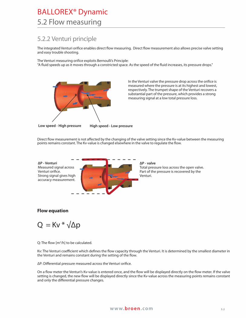
5.2.2 Venturi principle The integrated Venturi orifice enables direct flow measuring. Direct flow measurement also allows precise valve setting and easy trouble shooting. The Venturi measuring orifice exploits Bernoulli’s Principle:”A fluid speeds up as it moves through a constricted space. As the speed of the fluid increases, its pressure drops.”
In the Venturi valve the pressure drop across the orifice is measured where the pressure is at its highest and lowest, respectively. The trumpet shape of the Venturi recovers a substantial part of the pressure, which provides a strong measuring signal at a low total pressure loss.
Direct flow measurement is not affected by the changing of the valve setting since the Kv-value between the measuring points remains constant. The Kv-value is changed elsewhere in the valve to regulate the flow.
Flow equation
Q = Kv * √Δp
Q: The !ow [m3/h] to be calculated.
Kv: The Venturi coe&cient which de"nes the !ow capacity through the Venturi. It is determined by the smallest diameter in the Venturi and remains constant during the setting of the !ow.
ΔP: Di4erential pressure measured across the Venturi ori"ce.
On a !ow meter the Venturi’s Kv-value is entered once, and the !ow will be displayed directly on the !ow meter. If the valve setting is changed, the new !ow will be displayed directly since the Kv-value across the measuring points remains constant and only the di4erential pressure changes.
5.2 Flow measuring
ΔP - valveTotal pressure loss across the open valve.Part of the pressure is recovered by the Venturi.
ΔP - Venturi Measured signal across Venturi ori"ce.Strong signal gives high accuracy measurement.
High speed - Low pressureLow speed - High pressure

B
A
C
ED
5.3
BALLOREX® Dynamic
5.3.1 DesignAutomatic flow limiter and control valveSince the setting of the valve is done by a horizontal reduction of the inlet area, it has no effect on the vertical stroke length of the actuators. Combined with the built-in pressure regulator this provides 100% control authority in all situations.
A) 100% control valve authorityThe actuator has 100% control authority and full actuator stroke, regardless of the pre-setting. Therefore the valve will react instantly to the signal from the BMS and adjust the flow accordingly.
B) Direct flow measuringTest points for flow meter connection.
C) Flow limiterSetting the design flow rate is simple and easily done with the enclosed pre-setting tool.
D) Integrated VenturiThe Venturi orifice enables direct flow measuring.
E) Differential pressure regulatorThe integrated regulator maintains a constant differential pressure across the valve opening. The required flow is thereby kept constant regardless of pressure fluctuations in the system.
5.3 Product properties

5.3
TU
TU
TU
TU
TU=Terminal unit
BALLOREX® Dynamic
Rough pre-setting
To find the right setting the design flow rate is looked up in a flow diagram.
For a BALLOREX® Dynamic 890 l/h corresponds to a setting of approx. 32% on a DN 15H valve. Consult the flow diagram to find the correct setting for the design flow rate required.
The scale on the pre setting tool is read against the marking on the brass housing on the valve.
Each marking on the scale indicates 10%.
5.3.5 Pump settingThe balancing procedure as such becomes unnecessary when installing the BALLOREX® Dynamic. The valves are simply set to the required flow rate and will compensate for pressure fluctuations in the system. Therefore the hydronic balance in the system is ensured.
When all valves are set to the required flow rate, the pump head should be minimized in order to avoid unnecessary energy consumption.
This ensures that the pump head is reduced to the optimal point, which is where the pump delivers only as much pressure as the index valve needs to be working properly.
The optimal pump setting is easily found when commissioning the BALLOREX® Dynamic.
When setting the BALLOREX® Dynamic valves the pump is set to its maximum capacity. After setting all valves the flow meter is connected to the index valve, which is the valve that has the least differential pressure available. Typically it would be the valve placed highest and remotest from the pump.
The pump is then adjusted downwards until the flow on the index valve starts to decrease. This point is the minimum pressure required, for the operating range of the valve to start. To be sure that sufficient pressure is available, the pump is adjusted slightly back upwards until the design flow rate is displayed on the flowmeter again.
Hydronic balance is now provided by the BALLOREX® Dynamic valves and the pump head kept at a minimum.
5.3 Product properties
Setting ≈ 100% Setting ≈ 32%
76mm
35mm
95mm
5.4
5.4 Product data sheet
BALLOREX® Dynamic
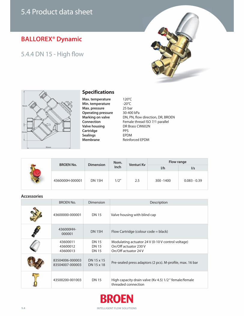
5.4.4 DN 15 - High !ow
BROEN No. Dimension Description
43600000-000001 DN 15 Valve housing with blind cap
436000HH-000001
DN 15H Flow Cartridge (colour code = black)
436000114360001243600013
DN 15 DN 15 DN 15
Modulating actuator 24 V (0-10 V control voltage)On/O4 actuator 230 V On/O4 actuator 24 V
83504006-00000383504007-000003
DN 15 x 15DN 15 x 18
Pre-sealed press adaptors (2 pcs). M-pro"le, max. 16 bar
43500200-001003 DN 15 High capacity drain valve (Kv 4.5) 1/2 “ female/female threaded connection
BROEN No. DimensionNom.
InchVenturi Kv
Flow range
l/h I/s
4360000H-000001 DN 15H 1/2” 2.5 300 -1400 0.083 - 0.39
Accessories
Specifications
Max. temperature 120°C Min. temperature -20°C Max. pressure 25 bar Operating pressure 30-400 kPa Marking on valve DN, PN, flow direction, DR, BROEN Connection Female thread ISO 7/1 parallel Valve housing DR Brass CW602N Cartridge PPS
Sealings EPDM Membrane Reinforced EPDM

83 mm
49 mm
120 mm
5.4
5.4 Product data sheet
BALLOREX® Dynamic
5.4.6 DN 20 - High !ow
BROEN No. DimensionNom.
Inch
Venturi
Kv
Flow range
l/h I/s
4460000H-000001 DN 20H 3/4” 4.7 835 - 2,221 0.232 - 0.617
BROEN No. Dimension Description
44600000-000001 DN 20 Valve housing with blind cap
446000HH-000001 DN 20H Flow Cartridge (colour code = black)
436000114360001243600013
Modulating actuator 24 V (0-10 V control voltage)On/O4 actuator 230 V On/O4 actuator 24 V
84504006-00000384504007-00000384504008-000003
DN 20 x 15DN 20 x 18DN 20 x 22
Pre-sealed press adaptors (2 pcs). M-pro"le, max. 16 bar
44500200-001003 DN 20 High capacity drain valve (Kv 4.5) 1/2 “ female/female threaded connection
Accessories
Specifications
Max. temperature 120°C Min. temperature -20°C Max. pressure 25 bar Operating pressure 30-400 kPa Marking on valve DN, PN, flow direction, DR, BROEN Connection Female thread ISO 7/1 parallel Valve housing DR Brass CW602N Cartridge PPS
Sealings EPDM Membrane Reinforced EPDM

81 mm
56 mm
127 mm
5.4
5.4 Product data sheet
BALLOREX® Dynamic
5.4.8 DN 25 - High !ow
BROEN No. Dimension Description
45600000-000001 DN 25 Valve housing with blind cap
456000HH-000001 DN 25H Flow Cartridge (colour code = black)
436000114360001243600013
Modulating actuator 24 V (0-10 V control voltage)On/O4 actuator 230 V On/O4 actuator 24 V
85504006-000003 28 x 28 Pre-sealed press adaptors (2 pcs). M-pro"le, max. 16 bar
45500200-001003 DN 25 High capacity drain valve 1“ female/female threaded connection
Accessories
BROEN No. DimensionNom.
Inch
Venturi
Kv
Flow range
l/h I/s
4560000H-000001 DN 25H 1” 1,600 - 3,300 0.444 - 0.917
Specifications
Max. temperature 120°C Min. temperature -20°C Max. pressure 25 bar Operating pressure 30-400 kPa Marking on valve DN, PN, flow direction, DR, BROEN Connection Female thread ISO 7/1 parallel Valve housing DR Brass CW602N Cartridge PPS
Sealings EPDM Membrane Reinforced EPDM

81 mm
56 mm
127 mm
5.4
5.4 Product data sheet
BALLOREX® Dynamic
5.4.9 DN 32 - High !ow
BROEN No. Dimension Description
46600000-000001 DN 32 Valve housing with blind cap
466000HH-000001 DN 32H Flow Cartridge (colour code = black)
436000114360001243600013
Modulating actuator 24 V (0-10 V control voltage)On/O4 actuator 230 V On/O4 actuator 24 V
85504006-000003 28 x 28 Pre-sealed press adaptors (2 pcs). M-pro"le, max. 16 bar
Accessories
BROEN No. DimensionNom.
Inch
Venturi
Kv
Flow range
l/h I/s
4660000H-000001 DN 32H 1 ¼” 8.3 1,800 - 4,500 0.500 - 1.250
Specifications
Max. temperature 120°C Min. temperature -20°C Max. pressure 25 bar Operating pressure 30-400 kPa Marking on valve DN, PN, flow direction, DR, BROEN Connection Female thread ISO 7/1 parallel Valve housing DR Brass CW602N Cartridge PPS
Sealings EPDM Membrane Reinforced EPDM

5.6
BALLOREX® Dynamic 5.6 Actuators
Modulating actuator 24 V operating voltage
Thermo-electronic actuator for opening and closing valves in a direct proportion to the applied control voltage.Powerless control is by a 0-10V DC signal which is provided either by a room thermostat or, in most cases, by a central BMS system. If a control voltage is applied, the actuator opens the valve proportionally to the detected actuator travel.
Operating voltage 24 V AC, 50-60 Hz
Base position Normally closed
Operating power 2 W
Average actuation delay 30 s/mm
Control voltage 0-10 V DC
Actuator travel 4 mm
Actuating force 100 N+/-5%
Ambient temperature 0 to +60°C
Protection class IP 54
CE conformity EN 60730
Connecting cable White /1 m/30 g
The actuator mechanism uses a PTC resistor-heated wax element and a compression spring. The wax element is heated by applying the operating voltage and moves the integrated piston. The force generated by this movement is transferred to the piston, thus opening or closing the valve.
Str
ok
e (
mm
)
5.6
BALLOREX® Dynamic
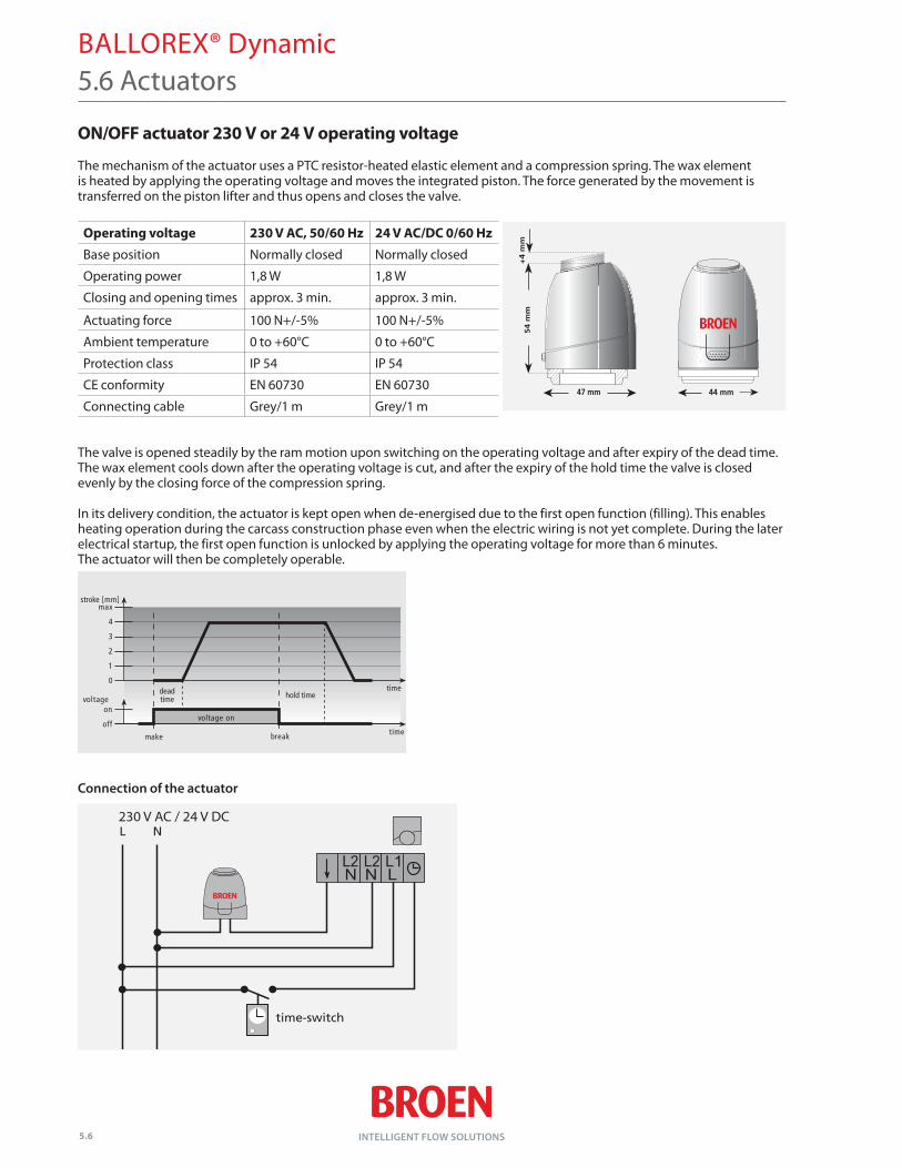
ON/OFF actuator 230 V or 24 V operating voltage
The mechanism of the actuator uses a PTC resistor-heated elastic element and a compression spring. The wax element is heated by applying the operating voltage and moves the integrated piston. The force generated by the movement is transferred on the piston lifter and thus opens and closes the valve.
Operating voltage 230 V AC, 50/60 Hz 24 V AC/DC 0/60 Hz
Base position Normally closed Normally closed
Operating power 1,8 W 1,8 W
Closing and opening times approx. 3 min. approx. 3 min.
Actuating force 100 N+/-5% 100 N+/-5%
Ambient temperature 0 to +60°C 0 to +60°C
Protection class IP 54 IP 54
CE conformity EN 60730 EN 60730
Connecting cable Grey/1 m Grey/1 m
The valve is opened steadily by the ram motion upon switching on the operating voltage and after expiry of the dead time. The wax element cools down after the operating voltage is cut, and after the expiry of the hold time the valve is closed evenly by the closing force of the compression spring.
In its delivery condition, the actuator is kept open when de-energised due to the first open function (filling). This enables heating operation during the carcass construction phase even when the electric wiring is not yet complete. During the later electrical start up, the first open function is unlocked by applying the operating voltage for more than 6 minutes. The actuator will then be completely operable.
Connection of the actuator
5.6 Actuators
230 V AC / 24 V DC