BallBot Brian Kosoris Jeroen Waning Bahati Gitego Yuriy Psarev 10/11/2011.
33
BallBot Brian Kosoris Jeroen Waning Bahati Gitego Yuriy Psarev 10/11/2011
-
Upload
eileen-barrett -
Category
Documents
-
view
221 -
download
1
Transcript of BallBot Brian Kosoris Jeroen Waning Bahati Gitego Yuriy Psarev 10/11/2011.

BallBot
Brian Kosoris
Jeroen Waning
Bahati Gitego
Yuriy Psarev
10/11/2011

System Overview
• Mechanical Structure• Base• Vertical structure• Landing gear
• Electronics• Sensors• Actuators/Motors
• Control System• State-space variable model• MatLab/Simulink code• Synthesis of 3D motion
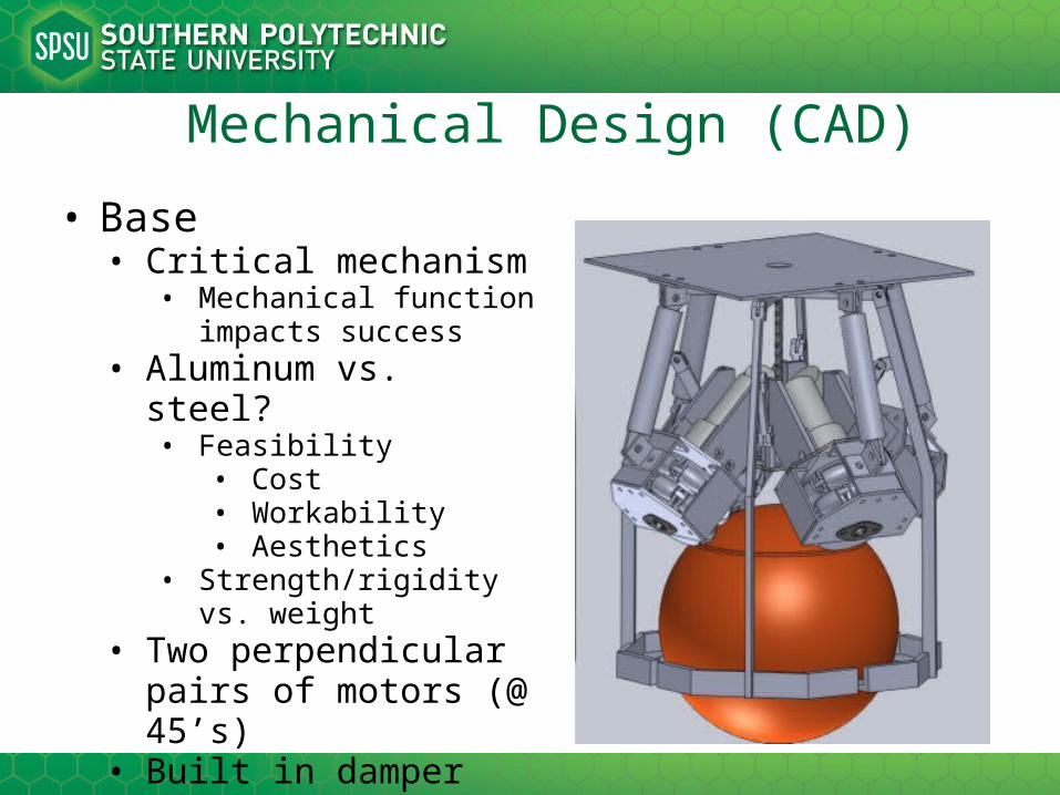
Mechanical Design (CAD)
• Base• Critical mechanism
• Mechanical function impacts success
• Aluminum vs. steel?• Feasibility
• Cost• Workability• Aesthetics
• Strength/rigidity vs. weight• Two perpendicular pairs
of motors (@ 45’s)• Built in damper for
vertical disturbances

Mechanical Design (CAD)
Bottom View
Top View
Mechanical Design
• Vertical structure• Simple aluminum frame• Multiple modular-plateau design
• Houses main CPU, IMU board, power supply, etc.• Modular/adjustable for optimization• Facilitates testing phase• Adjustable center of mass
• Serves as a three-dimensional inverted pendulum• Bolt-able design for quick adjustments

Mechanical Design (CAD)
• Landing gear• Supplemental ‘fail-safe’
design• Protects investment• Backup if minimum
success criteria is not met• i.e. BallBot topples over
• Simple & effective• Worm-screw actuator
design• Encapsulates ball when
BallBot is balanced
Electrical Components
• New components• Micro ITX gigabyte board
• High-level CPU to run MatLab• Processes integer data from IMU board• Runs control algorithm to digest sensor data• Provides output to motor controllers• 100% onboard control for self-sufficiency
• A321 batteries x 30 for onboard power supply• Provides 12-16.5V (3-5A) to motors• Provides 5V for digital logic (IMU board and CPU)
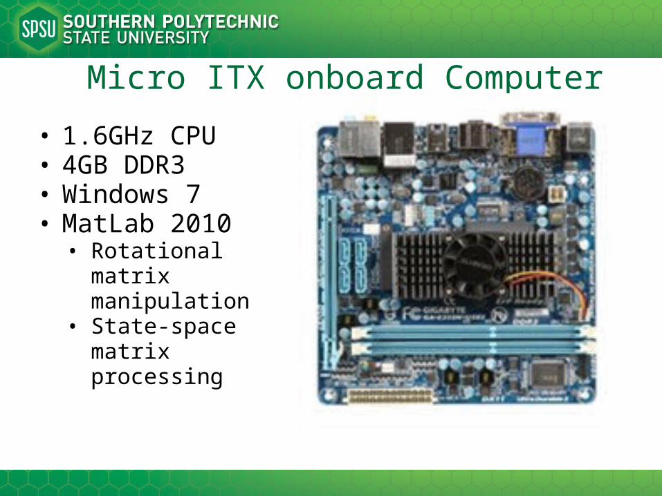
Micro ITX onboard Computer
• 1.6GHz CPU• 4GB DDR3• Windows 7• MatLab 2010
• Rotational matrix manipulation
• State-space matrix processing

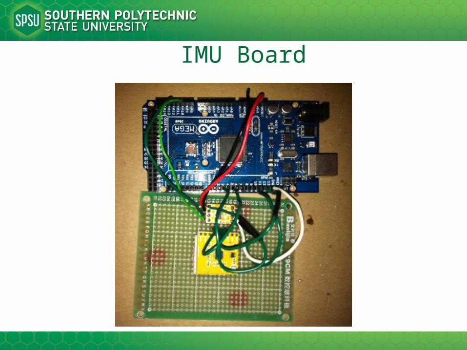
IMU Board
• Arduino ATmega2560• Microcontroller/microprocessor
• ADXL345 Accelerometer• Three-axis acceleration measurement unit
• IDG500 Gyroscope• Two-axis angular velocity measurement unit
• Provides real-time feedback of inertial orientation/rotation in 3D space
IMU Board
Sensor Data Processing
• IMU data will be relayed to onboard computer• MatLab will process complex state-space
equations and rotational matrices• Control system theory is used to model the
system for analysis of stability • Robotics synthesis
• Rotational matrices synthesize the robots orientation and angular velocity
• MatLab will process the matrices to provide feedback to the Arduino which sends signals to the motor controllers
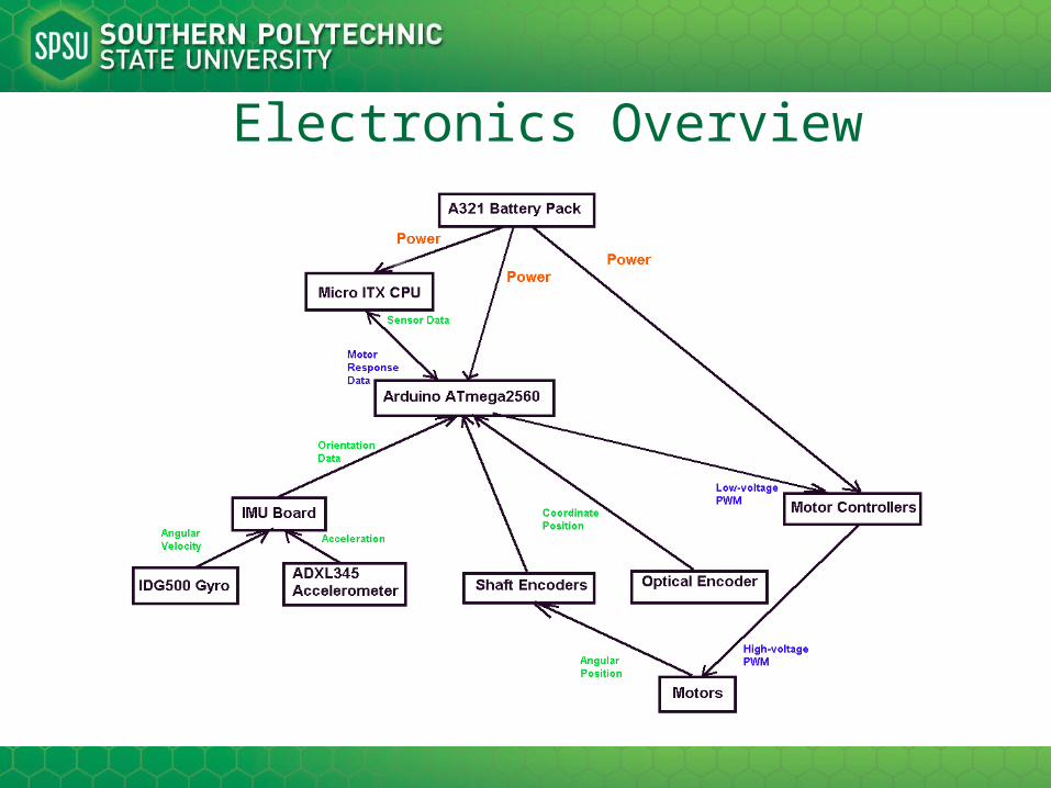
Electronics Overview
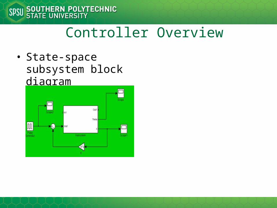
Controller Overview
• State-space subsystem block diagram

Controller Simulation
• Subsystem• Block-diagram representation of inside subsystem

Controller Simulation
• State-space modeling• x’ = Ax + Bu; y = Cx + Du
• MatLabA =
0 0 1.0000 0 0 0 0 1.0000 0 -198.9738 -0.0567 0.0567 0 42.8060 0.0092 -0.0092
B =
0 0 0 1
C =
1 0 0 0
D =0

State-space model (cont.)
controllability_matrix =
0 0.61661 -0.040635 19.844 0 -0.099717 0.0065714 -4.2689 0.61661 -0.040635 19.844 -2.6754 -0.099717 0.0065714 -4.2689 0.5025
Controllable_Rank_is =
4
observability_matrix =
1 0 0 0 0 0 1 0 0 -198.97 -0.056727 0.056727 0 13.715 0.0037383 -198.98

State-space model (cont.)Obsevabile_Rank_is =
4
Poles =
0 -6.5686 6.5168 -0.014085
Kd =
-36.621 -1698.7 -40.986 -423.26
pole_placement =
-14 -5 -240 -180
L =
438.93
-4372.5
51264
-26241
K_f =
-0.14086 -886.74 -1.4844 -141.81
K_i =
-0.0071253
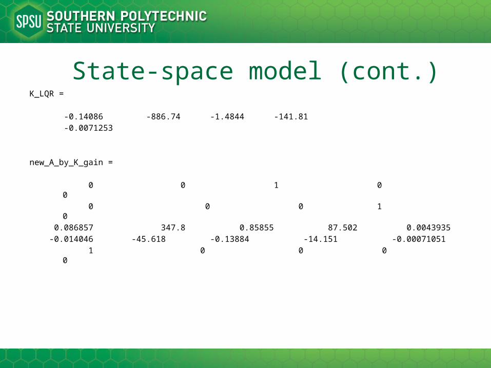
State-space model (cont.)K_LQR =
-0.14086 -886.74 -1.4844 -141.81
-0.0071253
new_A_by_K_gain =
0 0 1 0 0
0 0 0 1 0
0.086857 347.8 0.85855 87.502 0.0043935
-0.014046 -45.618 -0.13884 -14.151 -0.00071051
1 0 0 0 0
Robot Motion Synthesis
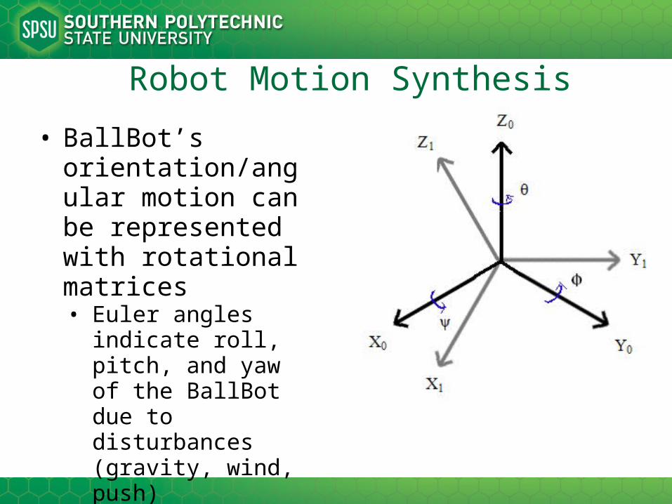
• BallBot’s orientation/angular motion can be represented with rotational matrices• Euler angles indicate
roll, pitch, and yaw of the BallBot due to disturbances (gravity, wind, push)
• Simplifies balancing/stability algorithm

Robot Motion Synthesis
• Frame 0 = 00X0Y0Z0 • Frame 1 = 01X1Y1Z1
• Position vector 0 = 3x1 matrix = [0 0 1] T
• Position vector 1 = [
] = 3x1 matrix• The angular velocities ωψ, ωϕ, ωθ
represent the data provided by the IMU board and are integrated to find position
Robot Motion Synthesis
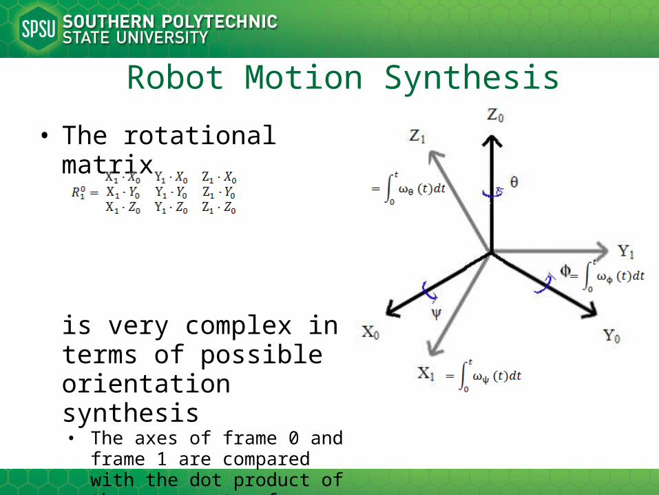
• The rotational matrix
is very complex in terms of possible orientation synthesis• The axes of frame 0 and frame
1 are compared with the dot product of the components of position vector 0 and position vector 1

Robot Motion Synthesis
• All possible orientations:• C1 = Cos(ψ), C2 = Cos(ϕ), C3 = Cos(θ)
• S1 = Sin(ψ), S2 = Sin(ϕ), S3 = Sin(θ)

Design Requirements – Major milestones
• In this phase of the design:• The mechanical structure must be completed by
October 20th, 2011• Electronics can then be integrated into assembly
(October 27th)• Arduino and MatLab communication algorithm
(November 2nd)• Begin preliminary testing (October 27th – November
10th)• Finalize complete algorithm (November 16th)• Optimization, aesthetics, minor revisions (November
27th)

Gantt Chart
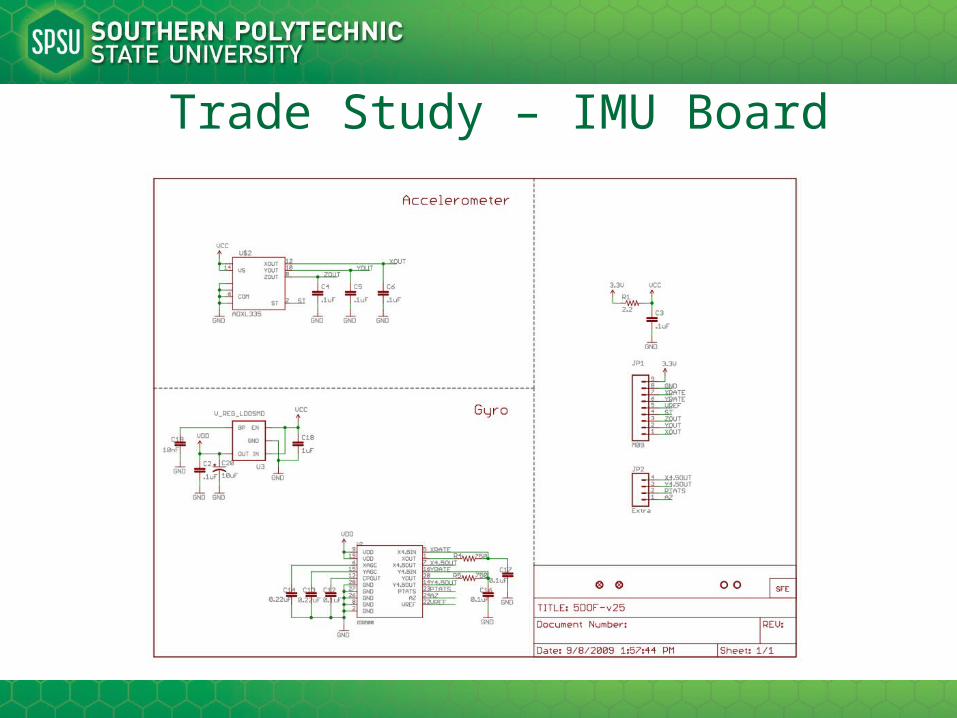
Trade Study – IMU Board
Trade Study – Accelerometer Filter
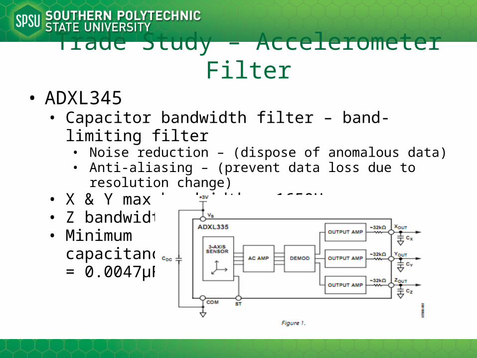
• ADXL345• Capacitor bandwidth filter – band-limiting filter
• Noise reduction – (dispose of anomalous data)• Anti-aliasing – (prevent data loss due to resolution change)
• X & Y max bandwidth – 1650Hz• Z bandwidth – 550Hz• Minimum
capacitance= 0.0047μF

Trade Study – Accelerometer Filter
• Bandwidth filter - capacitor selection• Capacitance decides bandwidth• Bandwidth indicates data resolution
Table 1 – Bandwidth vs. Capacitance
• Cx, Cy, Cz pins on ADXL345• Low-pass filtering• Noise reduction• 3-dB bandwidth equation
• F−3 dB = 1/(2π(32 kΩ) × C(X, Y, Z))

Trade Study – Accelerometer Filter
• F−3 dB = 1/(2π(32 kΩ) × C(X, Y, Z))• Approximates to F–3 dB = 5 μF/C(X, Y, Z)• 1650 Hz = 5 μF/0.00303 μF
• Cx = Cy = 0.00303 μF• 550 Hz = 5 μF/0.0091μF
• Cz = 0.0091 μF• These capacitor values will provide the highest data
resolution for• 1650 readings per second for X and Y acceleration
• Detect smallest possible acceleration in planar motion• 550 readings for Z acceleration
• The Z axis will thus represent the vertical axis of the BallBot from the center of the ball to the top of the BallBot• Then Z-axis data does not require high resolution
Trade Study – Accelerometer Filter
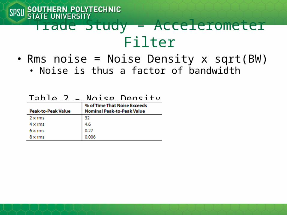
• Rms noise = Noise Density x sqrt(BW)• Noise is thus a factor of bandwidth
Table 2 – Noise Density

Trade Study – AccelerometerOperating Voltage
• The ADXL345 output is ratio-metric• The output sensitivity (or scale factor) varies
proportionally to the supply voltage.• VS = 3.6 V - output sensitivity = 360 mV/g• VS = 2 V - output sensitivity =195 mV/g.
• Arduino’s 3v3 pin supplies 3.3V• Sensitivity thus approximates to 320 mV/g to 340 mV/g (or
330 mV/g average)• Sensitivity estimated to be adequate for BallBot
• Arduino’s built-in serial monitor read consistent data• Only real-time testing will confirm

Trade Study – AccelerometerOperating Voltage
X-Y-Z sensitivity (voltage/gravity)
Data Sheet
References
• Arduino – microcontroller (libraries/tutorials)• www.arduino.cc
• SparkFun – sensors/electronics (datasheets)• www.sparkfun.com
• MatLab resource (control system toolbox, etc.)• http://
www.mathworks.com/matlabcentral/fileexchange/23931
• SolidWorks helpfile• http://
help.solidworks.com/2012/English/SolidWorks/sldworks/r_welcome_sw_online_help.htm
• Robot Modeling and Control (textbook)• Control Systems Engineering (textbook)

Title
• Contents