BACnet Controller Integration Technical...
52
LIT-1201531 Release 10.1 Building Technologies & Solutions www.johnsoncontrols.com 2019-10-14 BACnet Controller Integration Technical Bulletin
Transcript of BACnet Controller Integration Technical...
LIT-1201531
Release 10.1
Building Technologies & Solutions
www.johnsoncontrols.com
2019-10-14
BACnet Controller Integration TechnicalBulletin

ContentsContentsIntroduction.................................................................................................................................... 5
Summary of changes.......................................................................................................................... 5
BACnet Controller Integration overview..................................................................................... 5
BACnet Integration.............................................................................................................................. 6
BACnet Integration/Field Bus Integration object............................................................................ 7
Focus view.................................................................................................................................. 7
Diagnostics view........................................................................................................................ 7
Engineering view....................................................................................................................... 8
Summary view........................................................................................................................... 8
Hardware view (Field Bus integration only).......................................................................... 8
BACnet Integration and Field Bus Integration Auto Discovery filtering....................................... 8
BACnet Integration Auto Discovery filters............................................................................. 9
Field Bus Integration Auto Discovery filters........................................................................ 10
BACnet object support...................................................................................................................... 10
Unique device object identifiers............................................................................................ 12
Items in the Navigation tree on the SMP UI.................................................................................. 13
Commands............................................................................................................................... 13
Alarming................................................................................................................................... 17
Performance considerations for third-party BACnet devices...................................................... 17
Exposing network engine data to M-Series Workstations........................................................... 18
Supported network engine objects................................................................................................. 19
Exposing data as standard BACnet objects to other BACnet devices......................................... 20
Adjusting the poll rate for third-party BACnet devices................................................................. 20
Configuring a Network Engine as a BACnet IP to MS/TP Router................................................ 20
Auto-Created States Text.................................................................................................................. 21
Detailed procedures..................................................................................................................... 24
Connecting to BACnet devices......................................................................................................... 24
Exposing BACnet information.......................................................................................................... 24
Adding a BACnet Integration object............................................................................................... 26
Mapping BACnet IP Devices using Auto Discovery....................................................................... 27
Mapping BACnet IP devices manually............................................................................................ 28
Mapping BACnet Field Points using Auto Discovery..................................................................... 29
Mapping BACnet Field Points manually.......................................................................................... 32
Using the Relearn feature................................................................................................................ 34
Using the Engineering view to View and Edit Device Attributes (BACnetProperties)................................................................................................................................ 34
Field Bus Integration object — detailed procedures............................................................... 35
Adding BACnet MS/TP (Field Bus) Integrations............................................................................. 35
Manually adding BACnet MS/TP (Field Bus) Field Devices (online or offline)............................ 36
Adding BACnet MS/TP Field Devices online using Auto Discovery............................................. 37
Adding BACnet Devices to the BACnet and MSTP Integrations using the ImportIntegration Wizard................................................................................................................... 38
Adding extensions to an object....................................................................................................... 39
Adding a Trend Extension...................................................................................................... 39
Adding a Totalization Extension............................................................................................ 40
Adding an Alarm Extension................................................................................................... 41
Adding a Load Extension....................................................................................................... 42
Adding an Averaging Extension............................................................................................ 43
Deleting extensions from an object................................................................................................ 43
Copying extensions to a Field Device or Field Point (offline only).............................................. 44
Enabling the routing mode.............................................................................................................. 44
BACnet Controller Integration Technical Bulletinii

BACnet routing considerations.................................................................................................. 44
Related documentation............................................................................................................... 45
Troubleshooting........................................................................................................................... 46
BACnet System Integration troubleshooting guide...................................................................... 46
Product warranty.......................................................................................................................... 49
Software terms............................................................................................................................. 49
Patents........................................................................................................................................... 50
Single point of contact................................................................................................................. 50
iiiBACnet Controller Integration Technical Bulletin


IntroductionThis document describes how BACnet® controllers, both those from Johnson Controls and third-party suppliers, are integrated into the Metasys® system through the NAE, NCE, SNE, and SNC seriesnetwork engines, OAS series Open Application Server, or ODS series Open Data Server, all hereafterreferred to as supervisory controllers. This capability provides two major functions:
• First, this BACnet integration allows the objects within BACnet controllers to be interfaced withthe Site Management Portal.
• Second, this BACnet integration enables the supported supervisory controllers to providesupervisory control and monitoring functions for objects integrated from connected BACnetcontrollers. BACnet controllers can integrate with a supervisory controller using either BACnet IPor MS/TP communications.
Note: In this document, all NCE25, NAE35, and NAE45 content relates to Release 9.0.7. NAE55/NAE85/LCS85 are supported at R10.1. All SNE and SNC relates to 10.1.
The functions provided by the supervisory controllers for BACnet controllers are similar to thoseprovided to integrated N2 and LonTalk® controllers. The major difference is that the supervisorycontroller behaves as a BACnet gateway to the non-BACnet controllers, converting their data intoBACnet objects that reside within the supervisory controller. For integrated BACnet controllers,the supervisory controller provides BACnet mapper objects, which supplement the standardBACnet object data of the integrated controllers with additional attributes needed to perform theworkstation and building controller functions within the Metasys system. This document describesthose additional attributes.
Note: The term supervisory controller is used throughout this document to refer to thevariants of controllers that support BACnet controller integration, including NAE, NCE, SNE,and SNC series network engines, the OAS series Open Application Server, and the ODS seriesOpen Data Server. .
Summary of changes
The following information is new or revised:
• Included references to the SNE and SNC devices.
• Removed all references to Ready Access Portal.
• Added Averaging, Electric Demand Control, Electric Demand Monitoring, and Generator LoadControl to Table 1.
Important: Electric Demand Control, Electric Demand Monitoring, and Generator LoadControl objects are intended for use only in Japan.
• Added content in Auto-Created States Text.
BACnet Controller Integration overviewAs a BACnet integrator, the supervisory controller monitors and supervises a network of BACnetdevices and acts as a BACnet operator workstation for all integrated controllers. Data is presentedto the operator through the Site Management Portal UI of the supervisory controller. Other BACnetdevices on the network can read from and write to the BACnet objects within the supervisorycontroller.
5BACnet Controller Integration Technical Bulletin
BACnet Integration
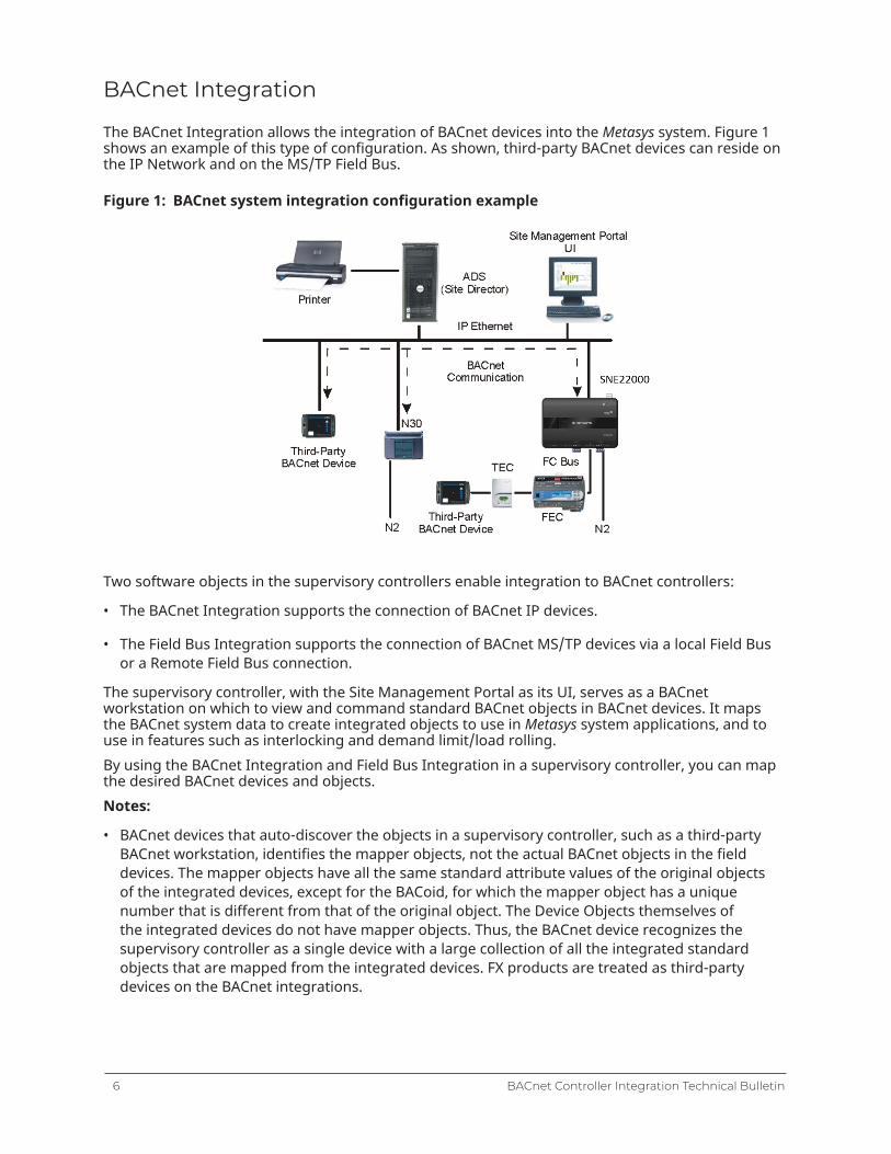
The BACnet Integration allows the integration of BACnet devices into the Metasys system. Figure 1shows an example of this type of configuration. As shown, third-party BACnet devices can reside onthe IP Network and on the MS/TP Field Bus.
Figure 1: BACnet system integration configuration example
Two software objects in the supervisory controllers enable integration to BACnet controllers:
• The BACnet Integration supports the connection of BACnet IP devices.
• The Field Bus Integration supports the connection of BACnet MS/TP devices via a local Field Busor a Remote Field Bus connection.
The supervisory controller, with the Site Management Portal as its UI, serves as a BACnetworkstation on which to view and command standard BACnet objects in BACnet devices. It mapsthe BACnet system data to create integrated objects to use in Metasys system applications, and touse in features such as interlocking and demand limit/load rolling.By using the BACnet Integration and Field Bus Integration in a supervisory controller, you can mapthe desired BACnet devices and objects.Notes:
• BACnet devices that auto-discover the objects in a supervisory controller, such as a third-partyBACnet workstation, identifies the mapper objects, not the actual BACnet objects in the fielddevices. The mapper objects have all the same standard attribute values of the original objectsof the integrated devices, except for the BACoid, for which the mapper object has a uniquenumber that is different from that of the original object. The Device Objects themselves ofthe integrated devices do not have mapper objects. Thus, the BACnet device recognizes thesupervisory controller as a single device with a large collection of all the integrated standardobjects that are mapped from the integrated devices. FX products are treated as third-partydevices on the BACnet integrations.
BACnet Controller Integration Technical Bulletin6

• The BACnet devices can discover MS/TP field devices and objects by enabling the BACnet IP toMS/TP routing feature in the NAE. See the Configuring a Network Engine as a BACnet IP to MS/TPRouter section.
Important: BACnet routing can greatly increase the amount of message traffic on the MS/TP bus. This can, in turn, cause a major reduction in performance. Refer to the Adjusting NAEnetwork sensitivity section in the NAE Commissioning Guide (LIT-1201519) for ways to improveperformance by adjusting network parameters.
BACnet Integration/Field Bus Integration object
In most instances, the supervisory controller has a BACnet integration.Use the BACnet Integrationto configure the parameters for BACnet integration in the supervisory controller that is monitoringBACnet IP devices. For more information about the BACnet Integration object, including attributesand commands, refer to the Object Help in the Metasys SMP Help (LIT-1201793).
Note: NAE/SNx's can only have one BACnet/IP Integration. Ideally, each device is mapped toonly one device.
Use the Field Bus Integration to connect BACnet MS/TP devices to a supervisory controller. Thespecific model of supervisory controller must either have an available RS-485 communicationconnection or use the remote field bus integration if the MS/TP devices are accessible through aBACnet IP to MS/TP router. In this case, the router provides the RS-485 communication instead ofthe supervisory controller.
Note: Make sure you map field devices under a remote field bus to only one supervisorycontroller. If you map the same remote controllers to multiple supervisors, these devicesmay cycle online and offline and you may experience slow startup performance. For morebackground on the remote field bus, refer to the ODS Commissioning Guide (LIT-12011944) andthe MS/TP Communications Bus Technical Bulletin (LIT-12011034).
The BACnet Integration object offers four views, while the Field Bus Integration object adds a fifthview:
• Focus view
• Diagnostics view
• Engineering view
• Summary view
• Hardware view (Field Bus integration only)
Note: Only the focus view is available during offline configuration with the SCT.
Focus view
The focus view contains basic user data including the name of the object and the device name ofthe host supervisory controller for the BACnet integration object.
Diagnostics view
The diagnostics view displays BACnet protocol diagnostic properties for troubleshooting purposes.Users with high-level privileges use this view.
Note: This view is not available during offline configuration with the SCT.
7BACnet Controller Integration Technical Bulletin

Engineering view
The engineering view of the BACnet Integration allows scanning the entire IP network to discoverand view data in BACnet devices that are connected on the network, whereas the Field Bus object’sengineering view shows the devices connected to the attached MS/TP bus. Advanced users (withthe appropriate access authority) use this view to see and change data in BACnet devices directly,whether or not the objects have been integrated to the supervisory controller. A user can then viewand command many more BACnet devices than just those that have been integrated and are visiblein the Site Management Portal All Items navigation tree.The engineering view contains the Integration Tree and Integration View panels. The IntegrationTree panel contains a list of known BACnet devices and their objects that are connected to thesupervisory controller. The Integration View panel displays the details about the BACnet device orobjects selected in the Integration Tree.After you create a new BACnet Integration or Field Bus Integration, the Integration Tree is emptyuntil you add the BACnet devices either manually or by using auto discovery.
Note: This view is not available for offline configuration with the SCT.
Summary view
The Summary view shows a list of all mapped devices and the current values of key data about eachdevice.
Note: This view is not available for offline configuration with the SCT.
Hardware view (Field Bus integration only)
The hardware view shows the Field bus trunk number, baud rate and network address.
BACnet Integration and Field Bus Integration Auto Discoveryfiltering
When you map BACnet IP devices or Field Bus integration devices using auto discovery, the list ofdevices may become so long that it is difficult to find a device in the list. You can use a number ofattributes in the Advanced Focus view to filter your view and make the list more manageable. Youcan configure this filtering using a collection of attributes located on the Advanced Focus view ofthe BACnet integration object or Field Bus Integration object.When devices are discovered, the discovery list displays the devices previously mapped by default.Additional devices are then added as they are discovered.
BACnet Controller Integration Technical Bulletin8

BACnet Integration Auto Discovery filters
• Device Discovery Range—This attribute is a list of filters arranged so that a device that matchesany of the list entries displays in the Auto Discovery list. The default attribute value is no entries,which allows all reachable devices to be discovered. Each list entry has the following parts:
- Broadcast Type - This entry filters the scope of the device discovery process at a BACnetnetwork level. This entry has three options:
- Local - Discovers devices only on the local BACnet IP network (network numberzero [0] is defined by BACnet as the local network).
- Remote - Discovers devices only on a particular BACnet network that must bespecified.
- Global - Discovers devices on all BACnet networks that are reachable (networknumber 65535 is defined by BACnet as the global broadcast network number).
- Network Number - The network number can only be entered when the Broadcast Type isset to Remote.
- Device Instance Low Limit - Each BACnet device is required to have a unique instancenumber at a site. The Device Instance Low Limit value specifies the lowest device instancenumber discovered on a network. The range for this value is 0 to 4194303. A device with aninstance number zero is not discovered when using this filter.
- Device Instance High Limit - The Device Instance High Limit value specifies the highestdevice instance number discovered on a network. The range for this value is 1 to 4194303and must be at least one number greater than the Device Instance Low Limit. A devicecannot have an instance number higher than the range limit.
• Preserve Discovered Devices—This attribute determines whether devices discovered during aprevious Auto Discovery operation are preserved during subsequent Auto Discovery operations.If the attribute is set to True, devices previously discovered are preserved. If the attribute is setto False, then devices previously discovered are not preserved. By default, this attribute is set toTrue.
Set the attribute to True to collect an inclusive list of devices by performing discovery multipletimes with different filter settings.
Set the attribute to False to narrow the discovery list to the current filter settings.
• Discover All As General BACnet Device— If the attribute is set to True, the BACnet/IPintegration allows for the discovery of JCI supervisory controllers. On both IP and MS/TPintegrations the devices are discovered as BACnet rather than JCI devices and this prevents youfrom using JCI features. However, setting the attribute to False does not prevent the discovery ofJCI IP field devices as JCI field devices are always discovered on the BACnet/IP integration.
Note: If you change the attribute after running Auto Discovery, we recommend you restartthe supervisory controller when configuration is complete.
9BACnet Controller Integration Technical Bulletin
• Requested Vendor ID—The BACnet Vendor ID is a numerical value assigned to the vendor ofthe device. By default, this attribute is empty (or at zero), allowing all vendors to be discovered.If a number other than zero is entered, only devices with a matching vendor ID display in thediscovery list. BACnet maintains a list of vendor IDs at http://www.bacnet.org.
• Page Size—This attribute filter applies only to point object discovery within a single device,and limits the number of displayed objects to a quantity within the display capability of the SiteManagement Portal (SMP) UI. When the page size reaches the limit, click Restart on the objectdiscovery list to move to the next page. If you click Restart on the last page of the discovery list,the object discovery runs again and produces a new page 1. The range of point objects displayedper page is 10 to 1,000.
Field Bus Integration Auto Discovery filters
Field Bus integrations are associated with a particular BACnet network number. During AutoDiscovery, only devices connected directly to that particular BACnet network are discovered. Adevice is classified as either a General BACnet Device or as an JCI Family BACnet Device. GeneralBACnet Devices are managed using standard BACnet services and properties. JCI Family BACnetDevices are managed using proprietary BACnet services and include proprietary properties in orderto improve performance and to display additional details about the device and its objects. Devicesthat are not JCI Family devices are always managed as General BACnet Devices.
• Discover All As General BACnet Device—This attribute determines whether a Johnson ControlsDevice in the FEC/FAC/VMA or CGM/CVM series family is classified as a JCI BACnet Device or asa General BACnet Device. By default, this attribute is set to False, and classifies the device as JCIBACnet Devices so that performance is optimized and proprietary properties display. When thisattribute changes, any previous discovery information clears and Auto Discovery must run again.
Note: If you change the attribute after running Auto Discovery, we recommend you restartthe NxE when configuration is complete.
• Requested Vendor ID—The BACnet Vendor ID is a numerical value assigned to the vendor ofthe device. By default, this attribute is empty (or at zero), allowing all vendors to be discovered.If a number other than zero is entered, only General BACnet Devices with matching vendorIDs display in the discovery list. JCI BACnet devices always display on the discovery list. BACnetmaintains a list of vendor IDs at http://www.bacnet.org.
BACnet object support
The Metasys system integrates and exposes objects as standard BACnet object types. The userconfigures and enables the BACnet Integration and Field Bus Integration feature in the supervisorycontrollers .The Metasys system supports a subset of standard BACnet object types, but does not supportintegration of any proprietary object types in other BACnet devices. Of the supported standardBACnet objects, only the required and optional attributes are viewable for non Metasys Seriescontrollers (referred to as General BACnet Device in this document); proprietary attributes are notsupported.The following list of BACnet object types are both those supported in the Metasys supervisorycontrollers for BACnet/Field Bus integration, and those exposed as BACnet objects to third-partyBACnet devices that discover the supervisory controller. Refer to the Object Dictionary in online Helpor the Network Engine Protocol Implementation Conformance Statement Technical Bulletin (LIT-1201532)for further details on objects supported.
Important: Electric Demand Control, Electric Demand Monitoring, and Generator Load Controlobjects are intended for use only in Japan.
BACnet Controller Integration Technical Bulletin10
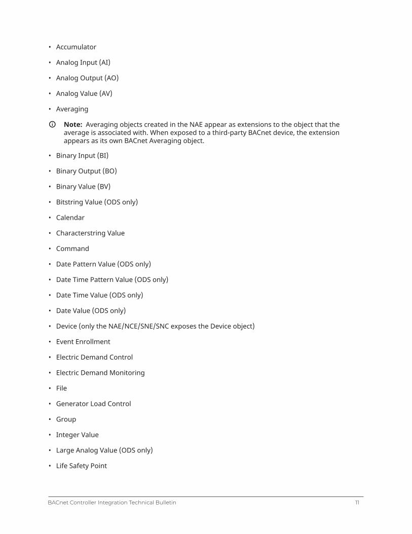
• Accumulator
• Analog Input (AI)
• Analog Output (AO)
• Analog Value (AV)
• Averaging
Note: Averaging objects created in the NAE appear as extensions to the object that theaverage is associated with. When exposed to a third-party BACnet device, the extensionappears as its own BACnet Averaging object.
• Binary Input (BI)
• Binary Output (BO)
• Binary Value (BV)
• Bitstring Value (ODS only)
• Calendar
• Characterstring Value
• Command
• Date Pattern Value (ODS only)
• Date Time Pattern Value (ODS only)
• Date Time Value (ODS only)
• Date Value (ODS only)
• Device (only the NAE/NCE/SNE/SNC exposes the Device object)
• Event Enrollment
• Electric Demand Control
• Electric Demand Monitoring
• File
• Generator Load Control
• Group
• Integer Value
• Large Analog Value (ODS only)
• Life Safety Point
11BACnet Controller Integration Technical Bulletin
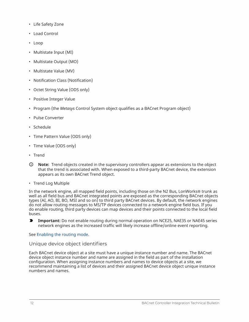
• Life Safety Zone
• Load Control
• Loop
• Multistate Input (MI)
• Multistate Output (MO)
• Multistate Value (MV)
• Notification Class (Notification)
• Octet String Value (ODS only)
• Positive Integer Value
• Program (the Metasys Control System object qualifies as a BACnet Program object)
• Pulse Converter
• Schedule
• Time Pattern Value (ODS only)
• Time Value (ODS only)
• Trend
Note: Trend objects created in the supervisory controllers appear as extensions to the objectthat the trend is associated with. When exposed to a third-party BACnet device, the extensionappears as its own BACnet Trend object.
• Trend Log Multiple
In the network engine, all mapped field points, including those on the N2 Bus, LonWorks® trunk aswell as all field bus and BACnet integrated points are exposed as the corresponding BACnet objectstypes (AI, AO, BI, BO, MSI and so on) to third party BACnet devices. By default, the network enginesdo not allow routing messages to MS/TP devices connected to a network engine field bus. If youdo enable routing, third party devices can map devices and their points connected to the local fieldbuses.
Important: Do not enable routing during normal operation on NCE25, NAE35 or NAE45 seriesnetwork engines as the increased traffic will likely increase offline/online event reporting.
See Enabling the routing mode.
Unique device object identifiers
Each BACnet device object at a site must have a unique instance number and name. The BACnetdevice object instance number and name are assigned in the field as part of the installationconfiguration. When assigning instance numbers and names to device objects at a site, werecommend maintaining a list of devices and their assigned BACnet device object unique instancenumbers and names.
BACnet Controller Integration Technical Bulletin12
Items in the Navigation tree on the SMP UI
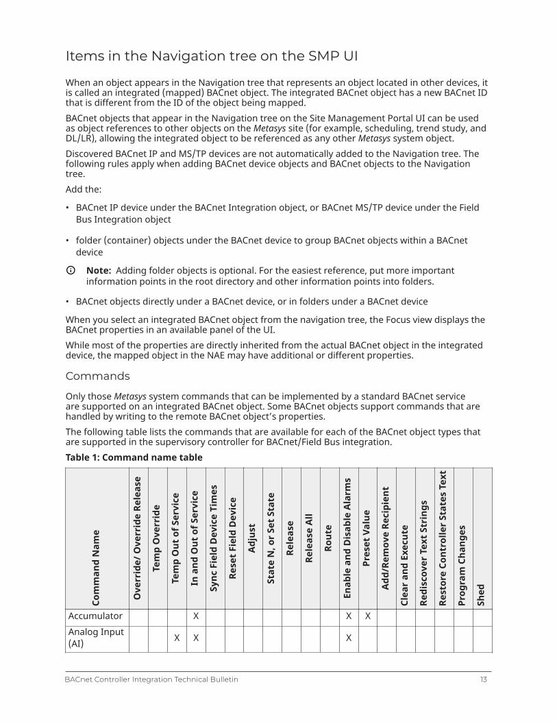
When an object appears in the Navigation tree that represents an object located in other devices, itis called an integrated (mapped) BACnet object. The integrated BACnet object has a new BACnet IDthat is different from the ID of the object being mapped.BACnet objects that appear in the Navigation tree on the Site Management Portal UI can be usedas object references to other objects on the Metasys site (for example, scheduling, trend study, andDL/LR), allowing the integrated object to be referenced as any other Metasys system object.Discovered BACnet IP and MS/TP devices are not automatically added to the Navigation tree. Thefollowing rules apply when adding BACnet device objects and BACnet objects to the Navigationtree.Add the:
• BACnet IP device under the BACnet Integration object, or BACnet MS/TP device under the FieldBus Integration object
• folder (container) objects under the BACnet device to group BACnet objects within a BACnetdevice
Note: Adding folder objects is optional. For the easiest reference, put more importantinformation points in the root directory and other information points into folders.
• BACnet objects directly under a BACnet device, or in folders under a BACnet device
When you select an integrated BACnet object from the navigation tree, the Focus view displays theBACnet properties in an available panel of the UI.While most of the properties are directly inherited from the actual BACnet object in the integrateddevice, the mapped object in the NAE may have additional or different properties.
Commands
Only those Metasys system commands that can be implemented by a standard BACnet serviceare supported on an integrated BACnet object. Some BACnet objects support commands that arehandled by writing to the remote BACnet object’s properties.The following table lists the commands that are available for each of the BACnet object types thatare supported in the supervisory controller for BACnet/Field Bus integration.Table 1: Command name table
Com
man
d N
ame
Ove
rrid
e/ O
verr
ide
Rele
ase
Tem
p O
verr
ide
Tem
p O
ut o
f Ser
vice
In a
nd O
ut o
f Ser
vice
Sync
Fie
ld D
evic
e Ti
mes
Rese
t Fie
ld D
evic
e
Adju
st
Stat
e N
, or S
et S
tate
Rele
ase
Rele
ase
All
Rout
e
Enab
le a
nd D
isab
le A
larm
s
Pres
et V
alue
Add/
Rem
ove
Reci
pien
t
Clea
r and
Exe
cute
Redi
scov
er T
ext S
trin
gs
Rest
ore
Cont
rolle
r Sta
tes
Text
Prog
ram
Cha
nges
Shed
Accumulator X X XAnalog Input(AI) X X X
13BACnet Controller Integration Technical Bulletin
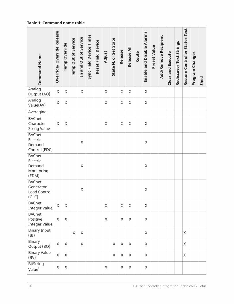
Table 1: Command name table
Com
man
d N
ame
Ove
rrid
e/ O
verr
ide
Rele
ase
Tem
p O
verr
ide
Tem
p O
ut o
f Ser
vice
In a
nd O
ut o
f Ser
vice
Sync
Fie
ld D
evic
e Ti
mes
Rese
t Fie
ld D
evic
e
Adju
st
Stat
e N
, or
Set S
tate
Rele
ase
Rele
ase
All
Rout
e
Enab
le a
nd D
isab
le A
larm
s
Pres
et V
alue
Add/
Rem
ove
Reci
pien
t
Clea
r an
d Ex
ecut
e
Redi
scov
er T
ext S
trin
gs
Rest
ore
Cont
rolle
r St
ates
Tex
t
Prog
ram
Cha
nges
Shed
AnalogOutput (AO) X X X X X X X
AnalogValue(AV) X X X X X X
AveragingBACnetCharacterString Value
X X X X X X
BACnetElectricDemandControl (EDC)
X X
BACnetElectricDemandMonitoring(EDM)
X X
BACnetGeneratorLoad Control(GLC)
X X
BACnetInteger Value X X X X X X
BACnetPositiveInteger Value
X X X X X X
Binary Input(BI) X X X X
BinaryOutput (BO) X X X X X X X X
Binary Value(BV) X X X X X X X
BitStringValue11 X X X X X X
BACnet Controller Integration Technical Bulletin14

Table 1: Command name table
Com
man
d N
ame
Ove
rrid
e/ O
verr
ide
Rele
ase
Tem
p O
verr
ide
Tem
p O
ut o
f Ser
vice
In a
nd O
ut o
f Ser
vice
Sync
Fie
ld D
evic
e Ti
mes
Rese
t Fie
ld D
evic
e
Adju
st
Stat
e N
, or
Set S
tate
Rele
ase
Rele
ase
All
Rout
e
Enab
le a
nd D
isab
le A
larm
s
Pres
et V
alue
Add/
Rem
ove
Reci
pien
t
Clea
r an
d Ex
ecut
e
Redi
scov
er T
ext S
trin
gs
Rest
ore
Cont
rolle
r St
ates
Tex
t
Prog
ram
Cha
nges
Shed
Calendar
Command X X
Date PatternValue1 X X X X X
Date TimePatternValue1
X X X X X
Date TimeValue1 X X X X X
Date Value1 X X X X X
Device X X X
ElectricDemandControl
X X X
ElectricDemandMonitoring
X X X
EventEnrollment(EEO)GeneratorLoad Control X X X
GroupLarge AnalogValue X X X X X X
Life SafetyPoint (LSP) X X
Life SafetyZone (LSZ) X X
Load Control X X X
Loop X X X
15BACnet Controller Integration Technical Bulletin
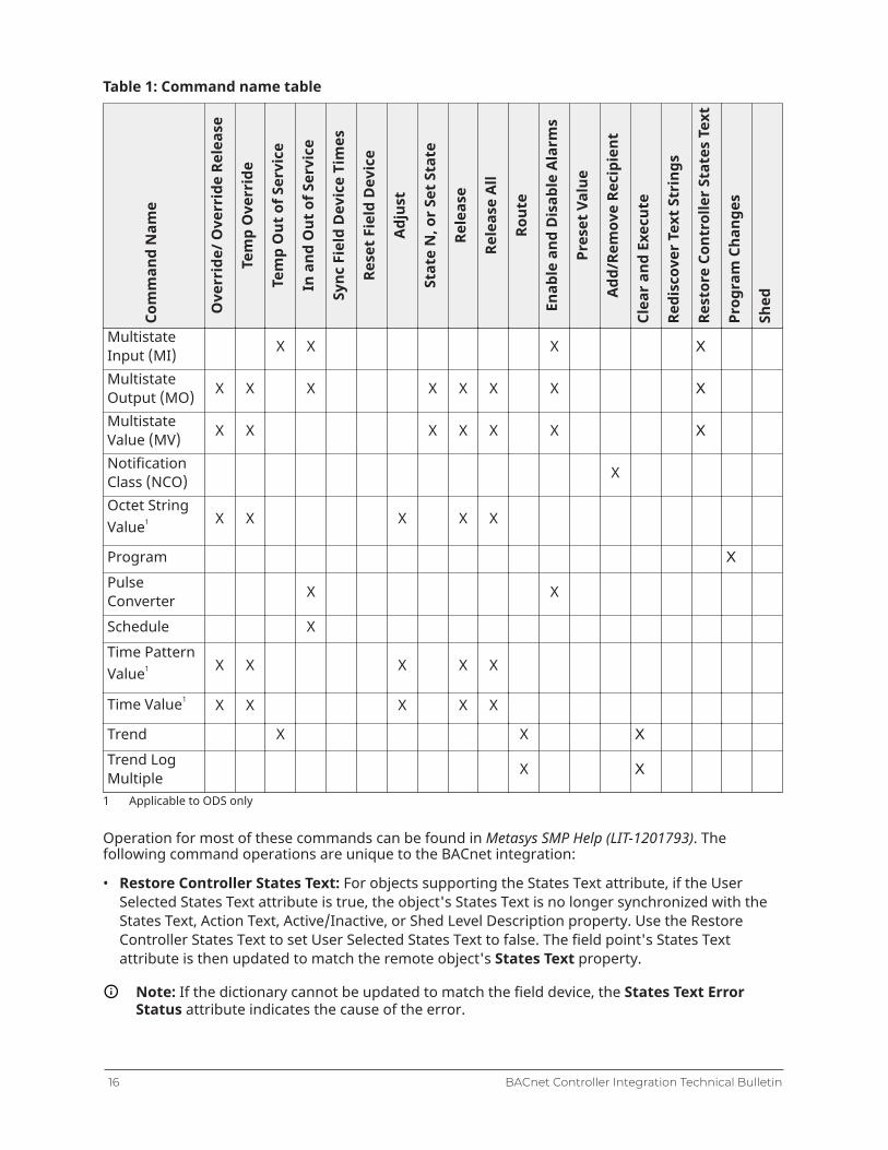
Table 1: Command name table
Com
man
d N
ame
Ove
rrid
e/ O
verr
ide
Rele
ase
Tem
p O
verr
ide
Tem
p O
ut o
f Ser
vice
In a
nd O
ut o
f Ser
vice
Sync
Fie
ld D
evic
e Ti
mes
Rese
t Fie
ld D
evic
e
Adju
st
Stat
e N
, or
Set S
tate
Rele
ase
Rele
ase
All
Rout
e
Enab
le a
nd D
isab
le A
larm
s
Pres
et V
alue
Add/
Rem
ove
Reci
pien
t
Clea
r an
d Ex
ecut
e
Redi
scov
er T
ext S
trin
gs
Rest
ore
Cont
rolle
r St
ates
Tex
t
Prog
ram
Cha
nges
Shed
MultistateInput (MI) X X X X
MultistateOutput (MO) X X X X X X X X
MultistateValue (MV) X X X X X X X
NotificationClass (NCO) X
Octet StringValue1 X X X X X
Program X
PulseConverter X X
Schedule XTime PatternValue1 X X X X X
Time Value1 X X X X X
Trend X X X
Trend LogMultiple X X
1 Applicable to ODS only
Operation for most of these commands can be found in Metasys SMP Help (LIT-1201793). Thefollowing command operations are unique to the BACnet integration:
• Restore Controller States Text: For objects supporting the States Text attribute, if the UserSelected States Text attribute is true, the object's States Text is no longer synchronized with theStates Text, Action Text, Active/Inactive, or Shed Level Description property. Use the RestoreController States Text to set User Selected States Text to false. The field point's States Textattribute is then updated to match the remote object's States Text property.
Note: If the dictionary cannot be updated to match the field device, the States Text ErrorStatus attribute indicates the cause of the error.
BACnet Controller Integration Technical Bulletin16
• State N: The State N Command is used by the Command object to write the Present Valueattribute by selecting a state. The first state in the drop-down box indicates No Action, and theremainder of the states indicate an Action from the Action array. If you choose to define yourown custom enumeration set for this object, be sure to enter No Action for the first entry.
• Add Recipient and Remove Recipient for the Notification Object: Use this command to addor remove the parent supervisory device as a notification recipient for the selected Notificationobject.
• Adjust: For the Loop object, the Adjust command writes the Setpoint attribute.
• Out of Service and Temporary Out of Service: If you want to write and make reliable PresentValue, first select an out of service or temporary out of service command to the input object,then set the Value before issuing the command. Objects that include this functionality includeAccumulator, AI, BI, MSI, Pulse Converter, and Schedule mappers.
Alarming
The supervisory controller accepts alarms from BACnet devices if those devices have a NotificationClass object with the supervisory controller specified as a recipient for the alarms, and if thesources of the alarms are mapped as integrated BACnet objects.The remote BACnet device notification class object has a destination Process ID for each recipiententry. By default, the supervisory controller accepts alarms for all valid Process ID values. For eachsupervisory controller, you can filter alarms and accept only those matching specific Process IDs.The supervisory controller's device object contains an attribute under the BACnet section of theFocus tab called Process Id List. Adding Process ID values to this attribute tells the supervisorycontroller to only accept alarms matching those Process IDs values. There are two special cases thattell the supervisory controller to accept alarms for any Process ID: if the list is empty (which is thedefault) or if the list contains a Process ID of 0.You can also configure the supervisory controller's Notification Class objects to send alarms toremote BACnet devices. The Metasys system audit trail then records the Alarm acknowledgmentsfrom the BACnet device.
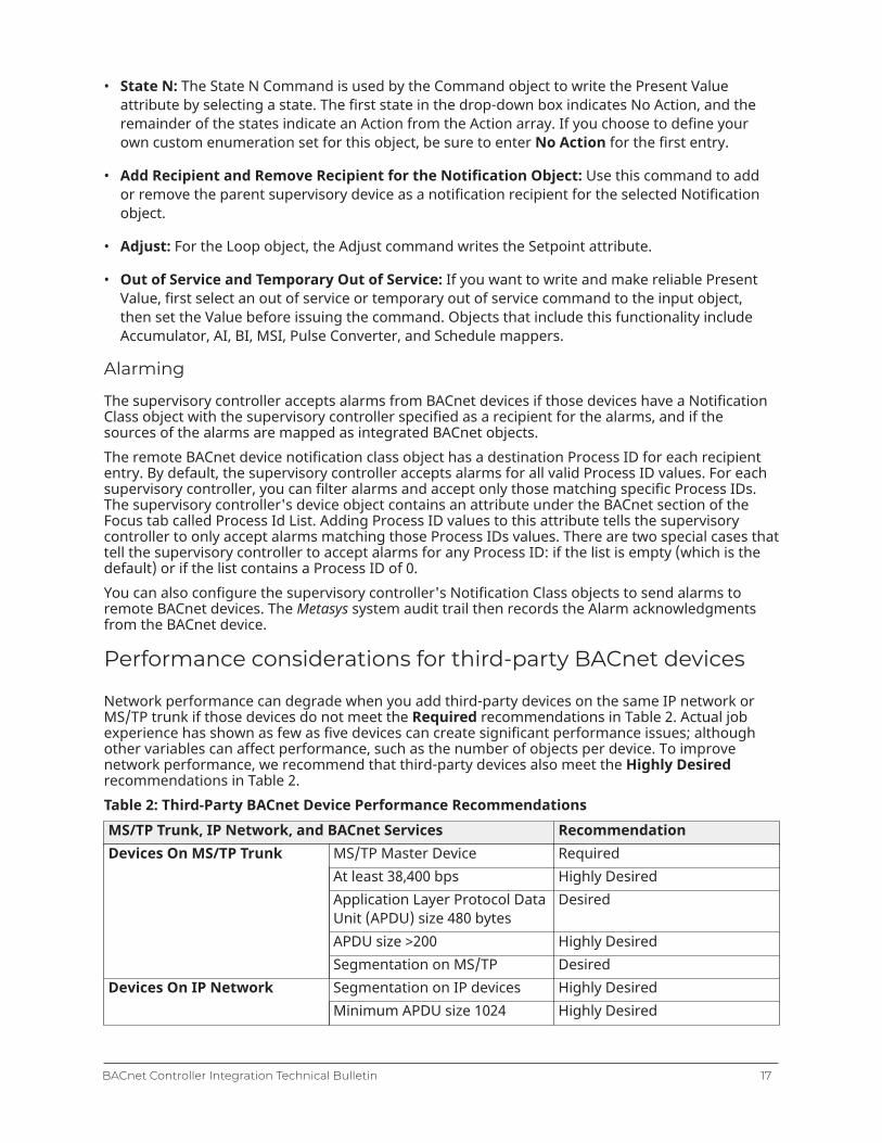
Performance considerations for third-party BACnet devices
Network performance can degrade when you add third-party devices on the same IP network orMS/TP trunk if those devices do not meet the Required recommendations in Table 2. Actual jobexperience has shown as few as five devices can create significant performance issues; althoughother variables can affect performance, such as the number of objects per device. To improvenetwork performance, we recommend that third-party devices also meet the Highly Desiredrecommendations in Table 2.Table 2: Third-Party BACnet Device Performance RecommendationsMS/TP Trunk, IP Network, and BACnet Services Recommendation
MS/TP Master Device RequiredAt least 38,400 bps Highly DesiredApplication Layer Protocol DataUnit (APDU) size 480 bytes
Desired
APDU size >200 Highly Desired
Devices On MS/TP Trunk
Segmentation on MS/TP DesiredSegmentation on IP devices Highly DesiredDevices On IP NetworkMinimum APDU size 1024 Highly Desired
17BACnet Controller Integration Technical Bulletin

Table 2: Third-Party BACnet Device Performance RecommendationsMS/TP Trunk, IP Network, and BACnet Services Recommendation
Conform at a minimum toBACnet Version 1 Revision 4specification
Protocol revision 15 or higher isdesired.
Device supports a minimum ofa B-SA profile or a B-SS profile.
Required
BACnet listed or Certified Highly Desired+ Read Property Multiple,Execute
Highly Desired
+ Subscribe COV, Execute Highly Desired
BACnet Services
+ Write Property Multiple,Execute
Highly Desired
Exposing network engine data to M-Series Workstations
To allow the M-Series Workstation or third-party BACnet devices to interface to network enginedevices, you must follow specific guidelines when configuring the network engine.All network engine objects that are exposed as BACnet standard objects can be accessed fromother BACnet devices and the M3 Workstation or M5 Workstation software.
Note: The network engine must be configured to expose General BACnet Device controllersto other third-party BACnet devices, such as a workstation. For example, for an M-Seriesworkstation to recognize the objects in a network engine that are mapped from a TECcontroller, the network engine's device object’s BACnet Integrated Objects attribute in thenetwork tab must be set to Include in Object List.
For information on configuring the network engine, refer to the Metasys SMP Help (LIT-1201793).For M-Series Workstations, configure the network engine with the following considerations.These considerations may or may not apply to other third-party BACnet devices. Consult thedocumentation for the third-party BACnet device for more information.
• Use ASCII text strings for BACnet Encoding Type in the Site object.
• Make the network engine Item Reference as short as possible because the network engine ItemReference is used as the basis for building up the BACnet OLE for Process Controls tag name inthe M-Series Workstations.
• Enable BACnet Intrinsic Alarming or set up Event Enrollment Alarming, including BACnet eventnotification (Notification Class objects), in the network engine for all objects that should reportevent messages to M-Alarm.
• Do not set up a domain name for the network engine's Device Object. Setting up a domain namecauses name changes for every NAE point object, making them unavailable to the M-SeriesWorkstation.
• For the standard M-Series workstations, use only supported enumeration sets, or the data doesnot appear correctly. For the list of enumeration sets, refer to the Metasys® System EnumerationSets Technical Bulletin (LIT-12011361).
• The safest alternative is to use the States set for the attributes that need enumerations.
BACnet Controller Integration Technical Bulletin18
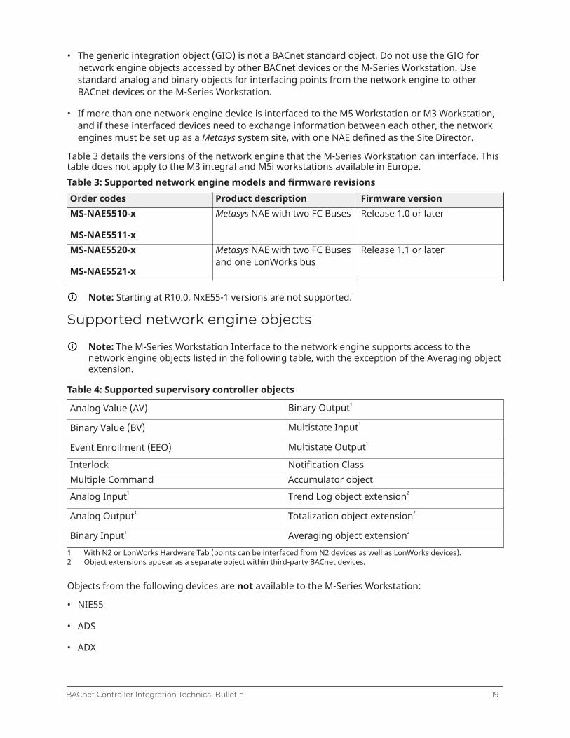
• The generic integration object (GIO) is not a BACnet standard object. Do not use the GIO fornetwork engine objects accessed by other BACnet devices or the M-Series Workstation. Usestandard analog and binary objects for interfacing points from the network engine to otherBACnet devices or the M-Series Workstation.
• If more than one network engine device is interfaced to the M5 Workstation or M3 Workstation,and if these interfaced devices need to exchange information between each other, the networkengines must be set up as a Metasys system site, with one NAE defined as the Site Director.
Table 3 details the versions of the network engine that the M-Series Workstation can interface. Thistable does not apply to the M3 integral and M5i workstations available in Europe.Table 3: Supported network engine models and firmware revisionsOrder codes Product description Firmware versionMS-NAE5510-x
MS-NAE5511-x
Metasys NAE with two FC Buses Release 1.0 or later
MS-NAE5520-x
MS-NAE5521-x
Metasys NAE with two FC Busesand one LonWorks bus
Release 1.1 or later
Note: Starting at R10.0, NxE55-1 versions are not supported.
Supported network engine objects
Note: The M-Series Workstation Interface to the network engine supports access to thenetwork engine objects listed in the following table, with the exception of the Averaging objectextension.
Table 4: Supported supervisory controller objects
Analog Value (AV) Binary Output11
Binary Value (BV) Multistate Input1
Event Enrollment (EEO) Multistate Output1
Interlock Notification ClassMultiple Command Accumulator object
Analog Input1 Trend Log object extension22
Analog Output1 Totalization object extension2
Binary Input1 Averaging object extension2
1 With N2 or LonWorks Hardware Tab (points can be interfaced from N2 devices as well as LonWorks devices).2 Object extensions appear as a separate object within third-party BACnet devices.
Objects from the following devices are not available to the M-Series Workstation:
• NIE55
• ADS
• ADX
19BACnet Controller Integration Technical Bulletin

• ODS
• OAS
Exposing data as standard BACnet objects to other BACnetdevices
Observe the following considerations when configuring the supervisory controller to third-partyBACnet devices:
• For BACnet Encoding Type in the Site object, specify a text string format that is supported by theother BACnet Devices (either ISO 10646 [UTF-8}, ISO 10646 [UCS-2], or Microsoft® double-bytecharacter sets [DBCS] code page 932 [Japanese Shift JIS]). For older BACnet equipment, ANSI X3.4[ASCII] is still supported.
Note: Starting at release 10.1 UTF-8 is the default, the recommendation is to use UTF-8 unlessother devices do not support it.
• For mapped objects that do not support intrinsic reporting at the remote device, enable BACnetIntrinsic Alarming or set up Event Enrollment Alarming, including BACnet Notification Classobjects, for all NAE/SNx objects that should report event messages to other BACnet workstations.
• The Generic Integration Object (GIO) is not a BACnet standard object. Do not use the GIO forNAE/SNx objects interfaced by BACnet devices. Use standard analog and binary NAE objectsinstead.
Adjusting the poll rate for third-party BACnet devices
The device’s poll rate governs how frequently a third-party BACnet device communicates with thesupervisory controller. A too fast poll rate may adversely affect the performance of the supervisorycontroller. By increasing the number of seconds the network engine waits before flagging a fielddevice as offline, you can minimize the number of false offline reports. Three different sensitivityoptions, each with a different set of values, are available: high, medium, and low. The defaultsetting for all network engines upgraded to Release 10.0 is medium. For further informationon poll rate, refer to the section Adjusting NAE network sensitivity in the NAE Comissioning Guide(LIT-1201519).
Note: The supervisory controller supports client Change of Value (COV) subscription, whichreduces the need for polling. The remote BACnet device must be capable of executing COVsubscription to take advantage of this service.
Configuring a Network Engine as a BACnet IP to MS/TPRouter
In its default configuration, third-party BACnet IP devices can only see the integrated BACnetobjects of the network engine. If the BACnet Routing mode is set to Enabled in the network engine,then other BACnet devices on the IP network are able to communicate directly with BACnet MS/TPdevices.See Enabling the routing mode.
Note: In most cases, enabling routing is not required.
BACnet Controller Integration Technical Bulletin20

Auto-Created States Text
In addition to the standard enumeration sets (which define the text displayed for each state ofa Binary and Multistate object) provided with the Metasys system, Auto-Created States Text canbe automatically added when a non-Johnson Controls device or select Johnson Controls-labeledBACnet device is discovered and added to a supervisory controller. An Auto-Created States Text canbe automatically assigned to the States Text field of a mapped object.The BACnet State_Text property is read when an online supervisory controller discovers BACnetobjects (BI, BO, BV, MSI, MSO, and MSV), and when a user views the object. When the value of theintegrated point's States Text attribute is updated and the user-selected states attribute is false, theMetasys system checks to see if the BACnet State_Text property associated with the object matchesa standard enumeration set used with Metasys States Text. Existing Auto-Created States Text arealso checked.If a match occurs, the Metasys system automatically assigns the matching States Text value tothe object. If no match occurs, the Metasys system automatically creates and assigns a newenumeration set. All new sets added at each supervisory controller are copied to the Site Director.New States Text added have the following limitations:
• 1,000 new enumeration sets maximum
• 260 Kb memory for all sets
• For any multi-value BACnet object (MSI, MSO, MSV), the number of states can be between 2 and500, with a maximum of 60 characters for any one state. Using the Command window, you canonly manually select from the first 32 states.
• Auto-Created States Text can only be automatically assigned to one object and cannot be editedusing the Metasys system.
• Auto-Created States Text is saved in the Site Director, and cached in the other devices.
• The Rediscover Text Strings device level command allows you to reset the States Text across anentire Metasys supervisory device; It rediscovers text strings from all the mapped BACnet objects.
Table 5: Auto-Created Enumeration Sets Usage by Metasys Product
Metasys Product Uses Auto-CreatedEnumeration Sets
Makes Changes to Auto-Created Enumeration Sets
Metasys Advanced ReportingSystem with EnergyEssentials
Yes Yes
ADS/ADX/ODS/OAS Yes YesNAE, NCE, SNE, SNC Yes YesSCT, SCT Simulation Yes NoCCT No No
Auto-Created Enumeration Sets are not translatable and do not appear in the dictionary viewertool. They are local to the site where they are defined.
Important: When using Auto-Created Enumeration Sets, you must upload the Site Directorfirst, then the network engine where you mapped the object. If you download from SCT,download the Site Director first, and then the network engine. You must do the procedurein this order, or the enumeration set text files do not match, and the state values are notindicated correctly.
21BACnet Controller Integration Technical Bulletin
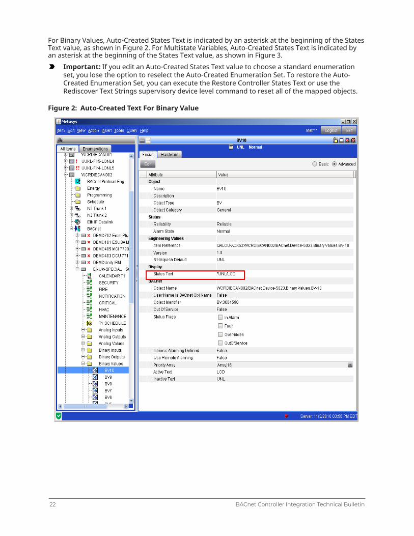
For Binary Values, Auto-Created States Text is indicated by an asterisk at the beginning of the StatesText value, as shown in Figure 2. For Multistate Variables, Auto-Created States Text is indicated byan asterisk at the beginning of the States Text value, as shown in Figure 3.
Important: If you edit an Auto-Created States Text value to choose a standard enumerationset, you lose the option to reselect the Auto-Created Enumeration Set. To restore the Auto-Created Enumeration Set, you can execute the Restore Controller States Text or use theRediscover Text Strings supervisory device level command to reset all of the mapped objects.
Figure 2: Auto-Created Text For Binary Value
BACnet Controller Integration Technical Bulletin22
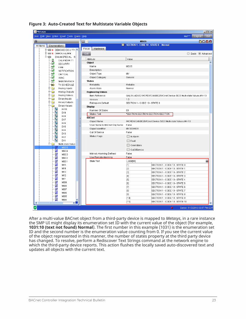
Figure 3: Auto-Created Text for Multistate Variable Objects
After a multi-value BACnet object from a third-party device is mapped to Metasys, in a rare instancethe SMP UI might display its enumeration set ID with the current value of the object (for example,1031:10 (text not found) Normal). The first number in this example (1031) is the enumeration setID and the second number is the enumeration value counting from 0. If you see the current valueof the object represented in this manner, the number of states property at the third party devicehas changed. To resolve, perform a Rediscover Text Strings command at the network engine towhich the third-party device reports. This action flushes the locally saved auto-discovered text andupdates all objects with the current text.
23BACnet Controller Integration Technical Bulletin
Detailed procedures
Connecting to BACnet devices
To connect and integrate BACnet devices into the Metasys system, connect the BACnet devices tothe same IP network as the supervisory controller used for the BACnet system integration.The devices must have the same BACnet Network Address and BACnet IP Port number (UDP port)as assigned to the supervisory controller to which the device is to be integrated. These values canbe seen in the NAE Focus tab.
Exposing BACnet information
About this task:
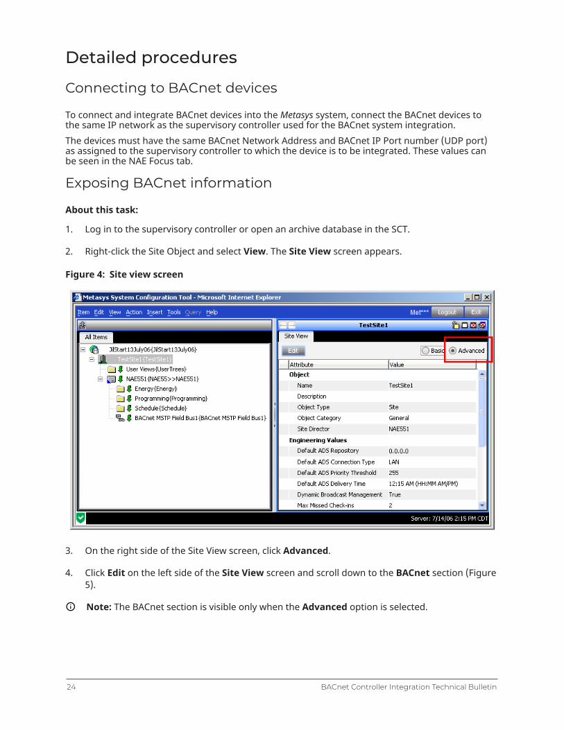
1. Log in to the supervisory controller or open an archive database in the SCT.
2. Right-click the Site Object and select View. The Site View screen appears.
Figure 4: Site view screen
3. On the right side of the Site View screen, click Advanced.
4. Click Edit on the left side of the Site View screen and scroll down to the BACnet section (Figure5).
Note: The BACnet section is visible only when the Advanced option is selected.
BACnet Controller Integration Technical Bulletin24

Figure 5: BACnet section enabled in site view
5. Set the BACnet Site field to True and set the BACnet Encoding Type for the encoding used bythe BACnet devices.
Note: The default BACnet Encoding Type is UTF-8. Many BACnet devices, including the N30Supervisory Controller, use ASCII for the BACnet Encoding Type. When connecting to an N30Network, choose ANSI X3.4 (US_ASCII) for the BACnet Encoding Type. Many devices suppliedin Japan use Microsoft DBCS code page 932 (Japanese Shift JIS). If connecting to anotherBACnet device, verify the BACnet Encoding Type with the manufacturer or supplier of thedevice. Selection of the wrong BACnet Encoding Type can result in unaccepted entries of textat the BACnet device, such as failed BACnet object descriptions and alarm acknowledgmentsfrom the Metasys system UI.
Note: The UTF-8 BACnet Encoding Type is also compatible with ASCII as long as extendedcharacters (for example, Çä╣ß ) are not used with ASCII devices.
6. Click Save. The NAE is now enabled to work with BACnet networks.
7. See Enabling the routing mode.
25BACnet Controller Integration Technical Bulletin

Adding a BACnet Integration object
About this task:The following process is applicable to online configuration in the Site Management Portal UI oroffline configuration in the SCT. These procedures assume both an online configuration and a con-nection between the NAE and the same network as the BACnet system or the integrating devices.The SCT contains no Engineering or Diagnostics views, as these are online features. In addition, touse Auto Discovery, the system must be online and connected to a BACnet network of devices.
Note: At startup of the supervisory controller, the BACnet Integration binds with the BACnetOID and uses the IP address from that bind. If you move a device to a different subnet,change the IP address of the device, or change the device's BACnet OID, you must restart thesupervisory controller to bind the BACnet OID with the new IP address.
1. On the Insert menu, select Integration. The Insert Integration Wizard, Select Object Typescreen appears.
Figure 6: Insert Integration Wizard (Select Object Type)
2. Select BACnet IPand click Next. The Destination screen appears.
3. Select the NAE/SNx to which to add the BACnet Integration object. After selecting the device,click Next. The Identifier screen appears.
4. Enter a unique name for the BACnet network of devices to integrate and click Next. TheConfiguration screen appears.
5. In most cases, accept the default Configuration parameters. (Refer to the BACnet Integrationobject in Metasys SMP Help (LIT-1201793) for a complete definition of the parameters.) ClickNext to accept the defaults. The Summary screen appears.
6. To change anything, click Back. If the Summary looks acceptable, click Finish to create theBACnet Integration object. You can now add extensions to the new object.
7. Add extensions as desired and click Done when finished. The Wizard closes.
BACnet Controller Integration Technical Bulletin26
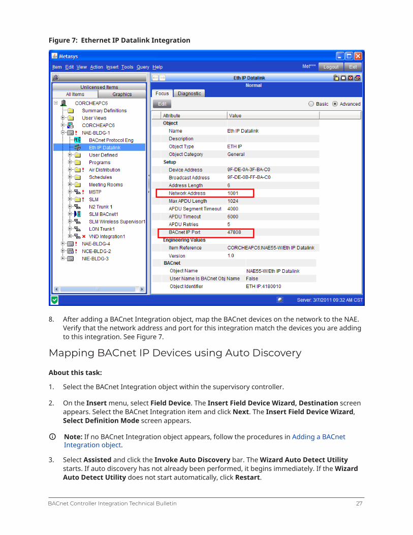
Figure 7: Ethernet IP Datalink Integration
8. After adding a BACnet Integration object, map the BACnet devices on the network to the NAE.Verify that the network address and port for this integration match the devices you are addingto this integration. See Figure 7.
Mapping BACnet IP Devices using Auto Discovery
About this task:
1. Select the BACnet Integration object within the supervisory controller.
2. On the Insert menu, select Field Device. The Insert Field Device Wizard, Destination screenappears. Select the BACnet Integration item and click Next. The Insert Field Device Wizard,Select Definition Mode screen appears.
Note: If no BACnet Integration object appears, follow the procedures in Adding a BACnetIntegration object.
3. Select Assisted and click the Invoke Auto Discovery bar. The Wizard Auto Detect Utilitystarts. If auto discovery has not already been performed, it begins immediately. If the WizardAuto Detect Utility does not start automatically, click Restart.
27BACnet Controller Integration Technical Bulletin
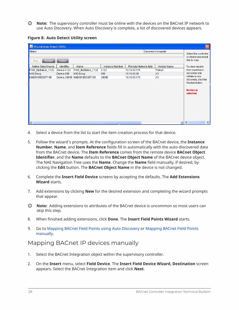
Note: The supervisory controller must be online with the devices on the BACnet IP network touse Auto Discovery. When Auto Discovery is complete, a list of discovered devices appears.
Figure 8: Auto Detect Utility screen
4. Select a device from the list to start the item creation process for that device.
5. Follow the wizard’s prompts. At the configuration screen of the BACnet device, the InstanceNumber, Name, and Item Reference fields fill in automatically with the auto-discovered datafrom the BACnet device. The Item Reference comes from the remote device BACnet ObjectIdentifier, and the Name defaults to the BACnet Object Name of the BACnet device object.The NAE Navigation Tree uses the Name. Change the Name field manually, if desired, byclicking the Edit button. The BACnet Object Name in the device is not changed.
6. Complete the Insert Field Device screens by accepting the defaults. The Add ExtensionsWizard starts.
7. Add extensions by clicking New for the desired extension and completing the wizard promptsthat appear.
Note: Adding extensions to attributes of the BACnet device is uncommon so most users canskip this step.
8. When finished adding extensions, click Done. The Insert Field Points Wizard starts.
9. Go to Mapping BACnet Field Points using Auto Discovery or Mapping BACnet Field Pointsmanually.
Mapping BACnet IP devices manually
1. Select the BACnet Integration object within the supervisory controller.
2. On the Insert menu, select Field Device. The Insert Field Device Wizard, Destination screenappears. Select the BACnet Integration item and click Next.
BACnet Controller Integration Technical Bulletin28
Note: If no BACnet Integration object appears, follow the procedures in Adding a BACnetIntegration object.
3. Select Manual and click Next.
4. Follow the wizard’s prompts. At the configuration screen of the BACnet device:
- Fill in the Instance Number manually.
- Fill in the Name field manually if the default data for the BACnet device is not satisfactory.
The Navigation Tree uses the field device name. Change the Name field manually, if desired, byclicking the Name field. The BACnet Object Name in the device is not changed.5. Complete the Insert Field Device screens by accepting the defaults. The Add Extensions
Wizard starts.
6. Add extensions by clicking New for the desired extension and completing the wizard promptsthat appear.
7. When finished adding extensions, click Done. The Insert Field Points Wizard starts.
Note: If no BACnet Integration object appears, follow the procedures in Adding a BACnetIntegration object.
8. Go to Mapping BACnet Field Points using Auto Discovery or Mapping BACnet Field Pointsmanually.
Mapping BACnet Field Points using Auto Discovery
About this task:Once one or more BACnet devices are configured, add BACnet field points that are mapped to BAC-net objects in the BACnet device.The supervisory controller must be online with the devices on the BACnet IP network to use AutoDiscovery. For mapping points offline, see Mapping BACnet Field Points manually.
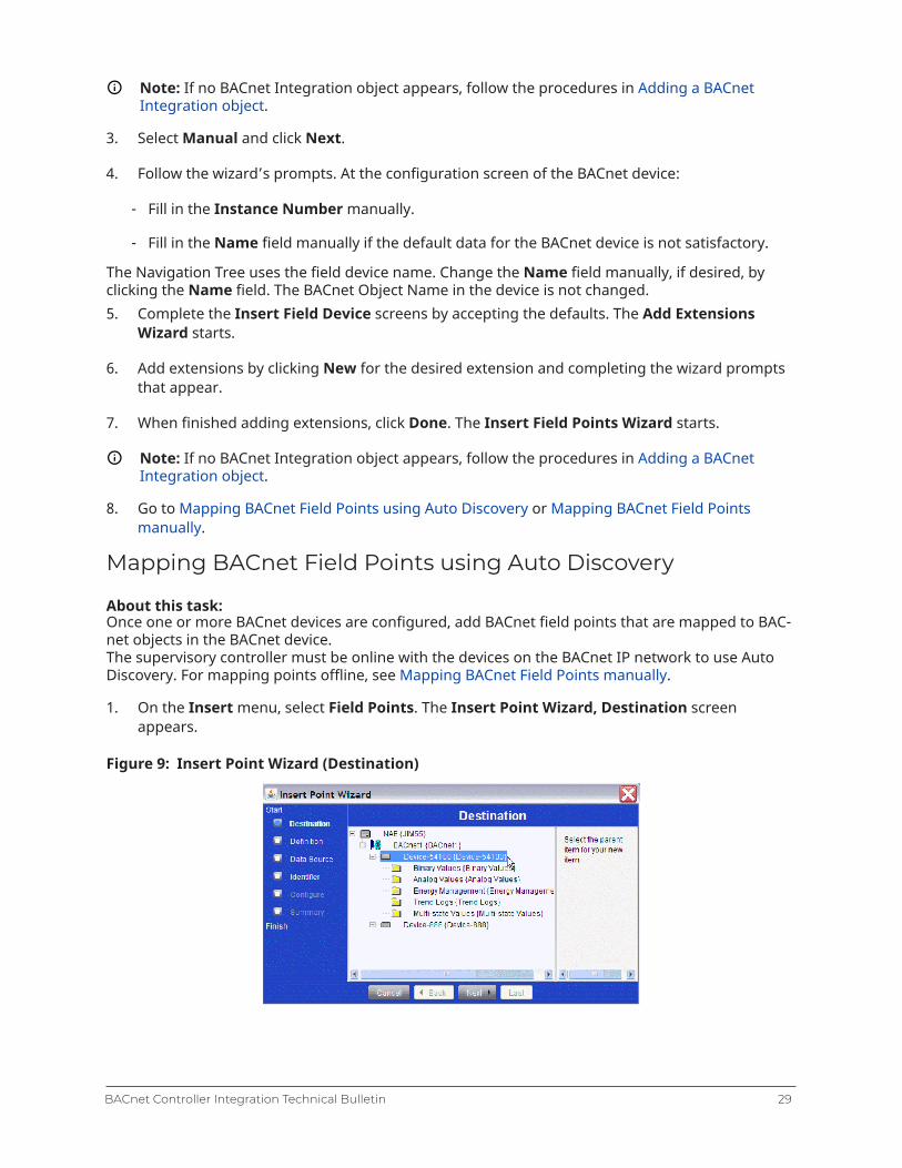
1. On the Insert menu, select Field Points. The Insert Point Wizard, Destination screenappears.
Figure 9: Insert Point Wizard (Destination)
29BACnet Controller Integration Technical Bulletin

The Insert Field Points Wizard starts automatically after inserting a Field Device. Because itselects the newly added device as the destination, the wizard opens to the Select Definition Modescreen bypassing the Destination screen.Add BACnet devices during the Mapping BACnet Field Points using Auto Discovery procedure. Toview the selectable devices, click the plus sign next to the BACnet Integration object to open the listof mapped BACnet devices.2. Select the BACnet device to which objects are to be integrated and click Next. The Insert Point
Wizard, Select Definition Mode screen appears.
3. Click Assisted and then click Invoke Auto Discovery. The Wizard Auto Detect Utility starts. Ifan auto discovery has not already run, it begins immediately. If the Wizard Auto Detect Utilityfails to start automatically, click Restart.
When Auto Discovery finishes, a list of discovered BACnet objects appears. The fields automaticallyfill in with the auto discovered data from the BACnet device. The Native Object Name is the BACnetObject Name in the device.
Note: If the total number of discovered points exceeds the limit, then the returned discoveryindicates Page 1 of X, where X is the total number of pages. A restart increments the page anddisplays the next set of discovered points. Each completion of the point mapping process alsoincrements the page. After the last page, the point mapping process begins again at Page 1.
Figure 10: Auto Detect Utility screen
BACnet Controller Integration Technical Bulletin30
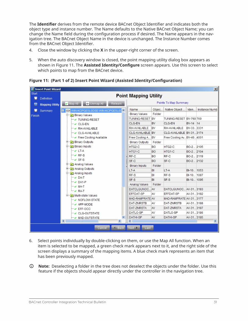
The Identifier derives from the remote device BACnet Object Identifier and indicates both theobject type and instance number. The Name defaults to the Native BACnet Object Name; you canchange the Name field during the configuration process if desired. The Name appears in the nav-igation tree. The BACnet Object Name in the device is unchanged. The Instance Number comesfrom the BACnet Object Identifier.4. Close the window by clicking the X in the upper-right corner of the screen.
5. When the auto discovery window is closed, the point mapping utility dialog box appears asshown in Figure 11. The Assisted Identity/Configure screen appears. Use this screen to selectwhich points to map from the BACnet device.
Figure 11: (Part 1 of 2) Insert Point Wizard (Assisted Identity/Configuration)
6. Select points individually by double-clicking on them, or use the Map All function. When anitem is selected to be mapped, a green check mark appears next to it, and the right side of thescreen displays a summary of the mapping items. A blue check mark represents an item thathas been previously mapped.
Note: Deselecting a folder in the tree does not deselect the objects under the folder. Use thisfeature if the objects should appear directly under the controller in the navigation tree.
31BACnet Controller Integration Technical Bulletin
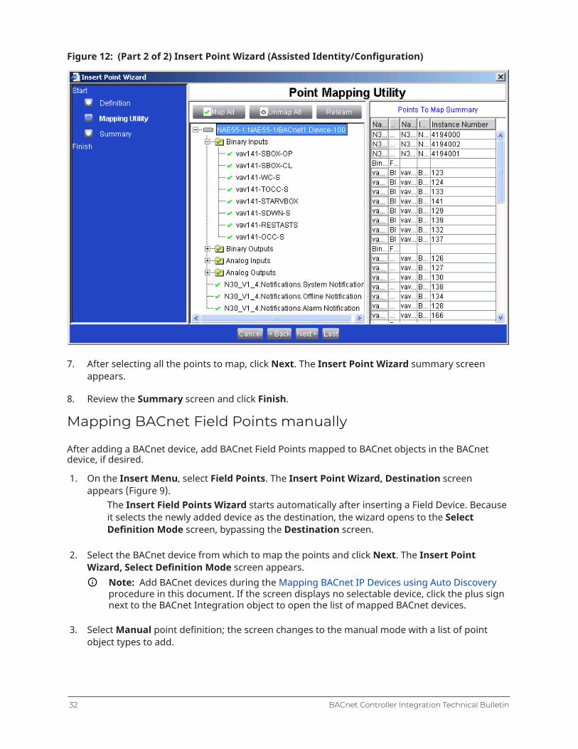
Figure 12: (Part 2 of 2) Insert Point Wizard (Assisted Identity/Configuration)
7. After selecting all the points to map, click Next. The Insert Point Wizard summary screenappears.
8. Review the Summary screen and click Finish.
Mapping BACnet Field Points manually
After adding a BACnet device, add BACnet Field Points mapped to BACnet objects in the BACnetdevice, if desired.
1. On the Insert Menu, select Field Points. The Insert Point Wizard, Destination screenappears (Figure 9).
The Insert Field Points Wizard starts automatically after inserting a Field Device. Becauseit selects the newly added device as the destination, the wizard opens to the SelectDefinition Mode screen, bypassing the Destination screen.
2. Select the BACnet device from which to map the points and click Next. The Insert PointWizard, Select Definition Mode screen appears.
Note: Add BACnet devices during the Mapping BACnet IP Devices using Auto Discoveryprocedure in this document. If the screen displays no selectable device, click the plus signnext to the BACnet Integration object to open the list of mapped BACnet devices.
3. Select Manual point definition; the screen changes to the manual mode with a list of pointobject types to add.
BACnet Controller Integration Technical Bulletin32
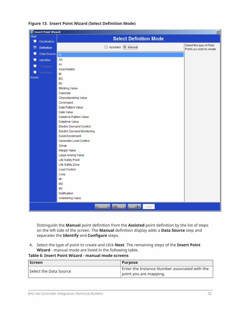
Figure 13: Insert Point Wizard (Select Definition Mode)
Distinguish the Manual point definition from the Assisted point definition by the list of stepson the left side of the screen. The Manual definition display adds a Data Source step andseparates the Identify and Configure steps.
4. Select the type of point to create and click Next. The remaining steps of the Insert PointWizard - manual mode are listed in the following table.
Table 6: Insert Point Wizard - manual mode screensScreen Purpose
Select the Data Source Enter the Instance Number associated with thepoint you are mapping.
33BACnet Controller Integration Technical Bulletin
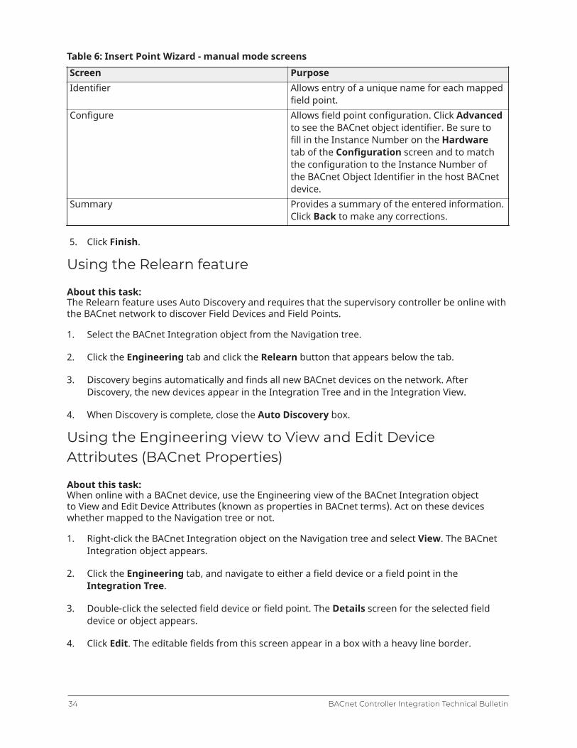
Table 6: Insert Point Wizard - manual mode screensScreen PurposeIdentifier Allows entry of a unique name for each mapped
field point.Configure Allows field point configuration. Click Advanced
to see the BACnet object identifier. Be sure tofill in the Instance Number on the Hardwaretab of the Configuration screen and to matchthe configuration to the Instance Number ofthe BACnet Object Identifier in the host BACnetdevice.
Summary Provides a summary of the entered information.Click Back to make any corrections.
5. Click Finish.
Using the Relearn feature
About this task:The Relearn feature uses Auto Discovery and requires that the supervisory controller be online withthe BACnet network to discover Field Devices and Field Points.
1. Select the BACnet Integration object from the Navigation tree.
2. Click the Engineering tab and click the Relearn button that appears below the tab.
3. Discovery begins automatically and finds all new BACnet devices on the network. AfterDiscovery, the new devices appear in the Integration Tree and in the Integration View.
4. When Discovery is complete, close the Auto Discovery box.
Using the Engineering view to View and Edit DeviceAttributes (BACnet Properties)
About this task:When online with a BACnet device, use the Engineering view of the BACnet Integration objectto View and Edit Device Attributes (known as properties in BACnet terms). Act on these deviceswhether mapped to the Navigation tree or not.
1. Right-click the BACnet Integration object on the Navigation tree and select View. The BACnetIntegration object appears.
2. Click the Engineering tab, and navigate to either a field device or a field point in theIntegration Tree.
3. Double-click the selected field device or field point. The Details screen for the selected fielddevice or object appears.
4. Click Edit. The editable fields from this screen appear in a box with a heavy line border.
BACnet Controller Integration Technical Bulletin34

The BACnet device displays only the required and optional attributes of the BACnet point object.Vendor-specific proprietary attributes do not appear.For attributes that support a command priority, such as the Present Value of an Analog Output(AO), the BACnet device displays the active value and priority. To change a value, enter an equalor higher priority. Clearing the value at the specified priority releases this priority and displays thevalue for the next highest priority.5. Make the desired changes and click Save.
Field Bus Integration object — detailed procedures
Adding BACnet MS/TP (Field Bus) Integrations
1. On the Insert menu, click Integration. The Insert Integration Wizard starts.
2. Follow the prompts to configure the integration using the information in the following table.Table 7: Insert Integration WizardScreen PurposeObject Type Select the type of integration (Field Bus).Destination Select the network engine that connects to the
integrating trunk.Identifier Type a unique name for the trunk. Each
integration under a device requires a uniquename. By default, the name of the newlyentered object has a number appended to keepit unique; therefore, if adding a BACnet MS/TPtrunk to a device for the first time, the defaultname is Field Bus.11
Configure22 Configure information about the integrationsuch as trunk number33 and a brief description.1
Note: If BACnet routing is enabled for thisnetwork engine, the Network Address onthe Hardware tab must be unique fromall other Field Bus and BACnet/IP networkaddresses on the site.
Summary View the basic parameters of the integrationjust added.
1 The local MS/TP trunks are 1 and 2. Some supervisory products support two MS/TP trunks. Numbers greater then 2are for a remote field bus. When selecting or adding a second BACnet MS/TP trunk, change the default trunk number(which is 1) on the Hardware tab to 2 and change the Network Address to a value not already used on the networkengine, typically one greater than the default value.
2 Typically, use the default values for Baud Rate Selection and Network Address. Change the Network Address if theactivity at the site also includes integrating third-party BACnet networks into the network engine. If BACnet routing isenabled for this network engine, the Network Address on the Hardware tab must be unique from all other networkaddresses on the site.
35BACnet Controller Integration Technical Bulletin

3 Trunk numbers 1 and 2 are used for local BACnet MS/TP trunks. Trunks that communicate through the BACnet IPconnection to a BACnet IP to MS/TP router (which provides the MS/TP wiring connection) use higher trunk numbersbetween 3 and 20. You must configure the router with an MS/TP network address number that is unique from allother network address numbers on the site. You must set the BACnet network address of the field bus to match theBACnet MS/TP network address number of the router. The BACnet IP network address of the router must match theBACnet IP network address of the NxE. In addition, one or more BBMDs may be required to allow BACnet IP broadcastmessages to reach the router. For more information on field bus capacity and quantity limits, refer to Metasys® SMPHelp (LIT-1201793).
3. Click Finish.
Manually adding BACnet MS/TP (Field Bus) Field Devices(online or offline)
About this task:Use the Insert Field Device Wizard to manually add BACnet MS/TP (field bus) field devices,whether the system is online or offline.
1. On the Insert menu, click Field Device. The Insert Field Device Wizard starts.
2. Select the trunk to which the field device is connected and click Next. The Insert Field DeviceWizard Select Definition Mode screen appears.
3. Click Manual. You are then prompted to select the class of device (JCI Family BACnet Device orGeneral BACnet Device).
Note: When using the SCT, the Assisted option appears dimmed because that method isunavailable when the system is offline.
4. For JCI Family BACnet Device, select a BACnet MS/TP address for the new device. All BACnetMS/TP addresses in the list are available because the address list updates each time a newcontroller object is created. After choosing a BACnet MS/TP address, click Next. Auto Discoveryis available only for online field devices. See the Adding BACnet MS/TP Field Devices onlineusing Auto Discovery section in this document.
Note: With JCI Family BACnet Device selected, you are prompted to enter the MAC Address,which is the physical hardware address of the device as determined by its address switchsettings. With General BACnet Device selected, you must enter the BACnet Instance Number,which is determined by software settings in the device. This value is entered on the Hardwaretab of the Identifier screen of the Wizard.
5. Click Next. The Insert Field Device Wizard Identifier screen appears.
6. Choose a unique name (within the parent object) for the new controller object and click Next.The Insert Field Device Wizard Configure screen appears. The fields of the Configure screenhave default data based on the previous information entered. This information includes theobject type and naming parameters of the new controller just created.
BACnet Controller Integration Technical Bulletin36
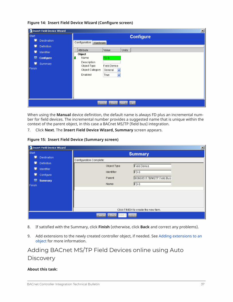
Figure 14: Insert Field Device Wizard (Configure screen)
When using the Manual device definition, the default name is always FD plus an incremental num-ber for field devices. The incremental number provides a suggested name that is unique within thecontext of the parent object, in this case a BACnet MS/TP (field bus) integration.7. Click Next. The Insert Field Device Wizard, Summary screen appears.
Figure 15: Insert Field Device (Summary screen)
8. If satisfied with the Summary, click Finish (otherwise, click Back and correct any problems).
9. Add extensions to the newly created controller object, if needed. See Adding extensions to anobject for more information.
Adding BACnet MS/TP Field Devices online using AutoDiscovery
About this task:
37BACnet Controller Integration Technical Bulletin

When logged in to a network engine through the Metasys system, the user can automatically dis-cover field devices. Do not use the Auto Discovery process through the SCT. However, in the SCT,the user can upload devices discovered on the network and added to the NAE database for archiveand editing.
1. On the Insert menu, select Field Device. The Insert Field Device Wizard Destination screenappears.
2. Select the BACnet MS/TP trunk to map the field devices to and click Next. The SelectDefinition Mode screen appears.
The Assisted Mode and Invoke Auto Discovery options are not available from the SCT. Upload anyrelevant online-generated information to an archive database in the SCT.3. Click Invoke Auto Discovery. The Auto Detect Utility starts.
4. After Auto Discovery is complete, select the device to map. If the device is already mapped, anotification message appears. If the device is not mapped, the Insert Field Device Identifierscreen appears.
5. Enter a unique identifier for the device and click Next. The Insert Field Device WizardConfigure screen appears.
6. Click Next. The Insert Field Device Summary screen appears.
7. If the Summary is satisfactory, click Finish (otherwise, click Back and correct any problems).This action creates the object and enables the process for adding extensions to the newcontroller object. See Adding extensions to an object for more information.
8. After adding all discovered devices, use the SCT to upload the NAE database to an archivedatabase in the SCT.
Note: See Troubleshooting (BACnet Trend Logs cannot be discovered) if the auto discoveryfails to find third-party Trend Log objects.
Adding BACnet Devices to the BACnet and MSTP Integrationsusing the Import Integration Wizard
About this task:
1. On the navigation tree, click the integration you want to add a device to.
2. On the Action menu, select Import Integration. The Open files screen appears.
3. Locate and select the import file that matches the integration. Then click Open. The ImportIntegration screen appears.
BACnet Controller Integration Technical Bulletin38

Figure 16: Import Integration Screen
4. Click Go. The Import Integration starts.
5. After the Import Integration is complete, a notification message appears.
If the import file does not match the integration, an Alert notice appears.6. Click OK. Repeat this process for each device you want to add.
Adding extensions to an object
About this task:Add trend, totalization, alarm, load, and averaging extensions to increase the functionality of a fielddevice or field point object.After creating a field device object or a field point object, the Extension Wizard automatically starts(skip to Step 3).
1. Select an object.
2. On the Action menu, select Show Extensions. The Extension Wizard starts.
3. Click New in the row next to the desired type of extension. Follow the prompts on the Wizardthat appears. See Adding a Trend Extension, Adding a Totalization Extension, or Adding anAlarm Extension for more information.
4. Follow the prompts to configure the extension and click Finish when done. The ExtensionWizard appears with the new extension listed in the appropriate row.
5. Click Done after adding the needed extensions. If the Extension Wizard launchesautomatically after creating the new field device object, the Field Device Extension screenopens next.
6. Add field points under the newly created controller object by clicking New in the Field Pointspanel of the Field Device Extension Wizard. See Manually adding BACnet MS/TP (Field Bus)Field Devices (online or offline) for instructions on adding BACnet MS/TP points.
Adding a Trend Extension
About this task:Adding trend extensions to objects allows the user to collect historical data for one or more attrib-utes of an object. Afterwards, view that data or forward the data to an Metasys Application Serverfor long-term storage. Use Trend Study to view Trend extensions from multiple items at the sametime.
39BACnet Controller Integration Technical Bulletin

1. In the Extensions Wizard, click New in the Trend row. The Insert Trend Wizard SelectAttribute screen appears.
The trended attribute defaults to Present Value. To trend a different attribute, click other. Theattribute list appears.
Figure 17: Insert Trend Wizard (Select Attribute Screen)
2. Select an attribute and follow the prompts in the Wizard to complete the addition of a TrendExtension.
3. Click Finish. The Extensions Wizard appears with the new attribute listed under Trend.
Adding a Totalization Extension
About this task:
1. In the Extensions Wizard, click New in the Totalization row. The Insert Totalization WizardSelect Attribute screen appears.
BACnet Controller Integration Technical Bulletin40
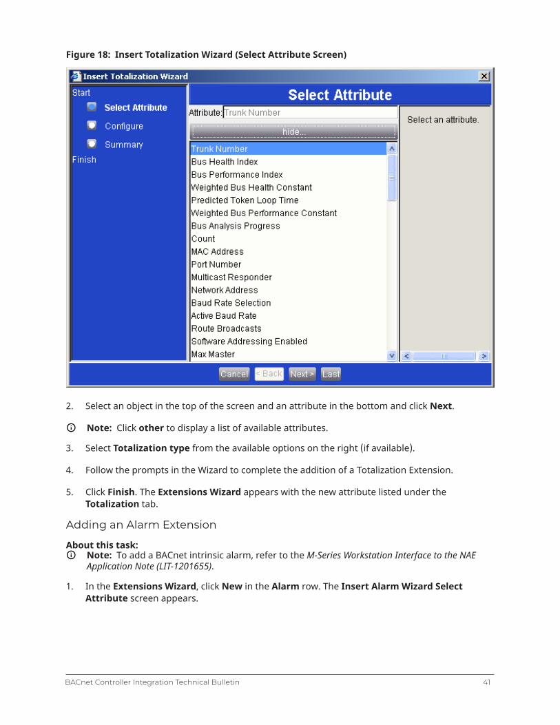
Figure 18: Insert Totalization Wizard (Select Attribute Screen)
2. Select an object in the top of the screen and an attribute in the bottom and click Next.
Note: Click other to display a list of available attributes.
3. Select Totalization type from the available options on the right (if available).
4. Follow the prompts in the Wizard to complete the addition of a Totalization Extension.
5. Click Finish. The Extensions Wizard appears with the new attribute listed under theTotalization tab.
Adding an Alarm Extension
About this task:Note: To add a BACnet intrinsic alarm, refer to the M-Series Workstation Interface to the NAEApplication Note (LIT-1201655).
1. In the Extensions Wizard, click New in the Alarm row. The Insert Alarm Wizard SelectAttribute screen appears.
41BACnet Controller Integration Technical Bulletin

Figure 19: Insert Alarm Wizard (Select Attribute Screen)
2. Select an object in the top of the screen and an attribute in the bottom of the screen and clickNext.
Note: Click other to display a list of available attributes.
3. Follow the prompts in the Wizard to complete the addition of an Alarm Extension.
4. Click Finish. The Extensions Wizard appears with the new attribute listed under theAlarmtab.
Adding a Load Extension
About this task:
1. In the Extensions Wizard, click New in the Load row. The Insert Load Wizard SelectAttribute screen appears.
2. Select an object in the top of the screen and an attribute in the bottom of the screen and clickNext.
Note: Click other to display a list of available attributes.
3. Follow the prompts in the Wizard to complete the addition of an Load Extension.
BACnet Controller Integration Technical Bulletin42
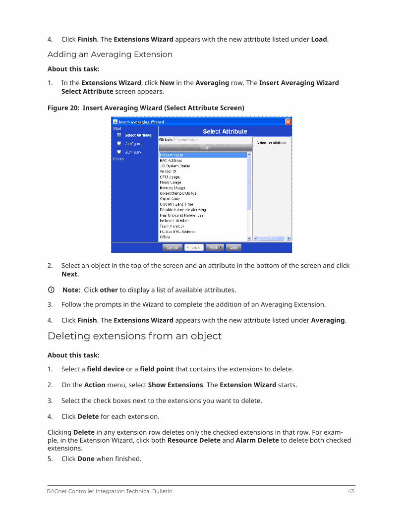
4. Click Finish. The Extensions Wizard appears with the new attribute listed under Load.
Adding an Averaging Extension
About this task:
1. In the Extensions Wizard, click New in the Averaging row. The Insert Averaging WizardSelect Attribute screen appears.
Figure 20: Insert Averaging Wizard (Select Attribute Screen)
2. Select an object in the top of the screen and an attribute in the bottom of the screen and clickNext.
Note: Click other to display a list of available attributes.
3. Follow the prompts in the Wizard to complete the addition of an Averaging Extension.
4. Click Finish. The Extensions Wizard appears with the new attribute listed under Averaging.
Deleting extensions from an object
About this task:
1. Select a field device or a field point that contains the extensions to delete.
2. On the Action menu, select Show Extensions. The Extension Wizard starts.
3. Select the check boxes next to the extensions you want to delete.
4. Click Delete for each extension.
Clicking Delete in any extension row deletes only the checked extensions in that row. For exam-ple, in the Extension Wizard, click both Resource Delete and Alarm Delete to delete both checkedextensions.5. Click Done when finished.
43BACnet Controller Integration Technical Bulletin

Copying extensions to a Field Device or Field Point (offlineonly)
About this task:
1. Select a field device or a field point that contains the extensions to copy.
2. On the Action menu, click Show Extensions. The Extension Wizard starts.
3. Select the check boxes for the extensions that you want to copy and click Copy CheckedExtensions at the bottom of the Wizard.
4. Click Done.
5. In the Navigation Tree, select the desired field device or field point destination.
6. On the Edit menu, click Paste. This adds the copied extensions to the selected field device orfield point.
7. Drag the field device or field point to the Display frame (on the right) to verify that the newextensions are correct.
Enabling the routing mode
Normally, third-party BACnet field devices only view mapper objects in the supervisory controller,which are representations of the real BACnet objects in the third-party BACnet field devices.Because the objects are representations, no extra network traffic is added to third-partyBACnet field devices. Enable the routing mode at the supervisory controller only if you needto communicate directly with the third-party BACnet field devices, such as when you arereprogramming from the third party’s engineering workstation, to directly pass BACnet messagesfrom the workstation through the supervisory controller to the third-party BACnet field devices.
BACnet routing considerationsBACnet routing is a technique by which data on one network data segment is passed to and fromanother network data segment. In the case of the network engine, this BACnet routing occurs whendata is passed from the IP side of the device to the MS/TP side of the device.If routing is disabled, the network engine provides an indirect (or proxy) method of obtaining thedata on its MS/TP network when a request is made from another device on the IP side of the device.With routing enabled, the network engine may no longer need detailed knowledge of the types ofdevices and services that reside on its MS/TP network–it simply passes the data request from onelink to the next and back again with as little interference as possible. This passing of informationbenefits those third-party vendors that have the need to directly access devices on the networkengine’s MS/TP network using tools from the IP network side.
Note: On a homogenous (or near-homogeneous) Johnson Controls network, you do not needto enable routing. Enabling routing requires the entire site to follow strict BACnet rules so theconsequences should be fully understood beforehand.
The routing function of the network engine is disabled by default. Routing can be enabled bysetting the Routing Mode attribute on the Network tab of the Device object view to Enabled. Youcan disable routing by setting the Routing Mode attribute to Disabled. Restarting the networkengine is not required when routing is enabled or disabled.
BACnet Controller Integration Technical Bulletin44

The Enable without Broadcasts setting of the Routing Mode attribute is used to reduce the networktraffic caused by enabling routing on an MS/TP network. If this option is used, it is difficult for third-party devices outside the network to discover any devices on a routed network using this settingbecause they rely on broadcast data for discovery. Because the data capacity of Ethernet IP is muchhigher than that of MS/TP, special care must be taken to avoid overloading the MS/TP bus whenrouting is enabled.All integrated points are visible in the network engine by default, including General BACnet Devices.A third-party device can view the entire list of integrated points by requesting the Object List of thenetwork engine. This request is part of the BACnet communication protocol used to help discoverobjects on other BACnet devices.If you want to have access to third-party integrated points within the network engine, there is abenefit to interfacing with mapped MS/TP points in the network engine rather than directly with theobjects in each MS/TP device. The network engine acts as a high-speed proxy for all data requestswithin its domain, which ensures the best performance. This is the default behavior for the networkengine and eliminates the need for enabling routing on the network engine. Routing should only beenabled if existing third-party tool configurations cannot support any other method.When routing is enabled, device configurations must follow more strict setup rules, andconfigurations that may have previously worked in non-routing situations may no longer work. Thesame setup rules apply for systems with routing enabled and static IP networks.Notes:
• Once routing is enabled on the network engine, all device identifiers within each device must beunique across all routed networks, and all network address numbers must be unique across allrouted networks.
• Be sure you have good reason before you enable routing. For example, if BACnet rules are notfollowed when routing is enabled, performance and intermittent issues could result. Or, if a third-party device exists or is added in the future, considerable work may be required to allow thedevice to work.
The BACnet Broadcast Receive Rate, BACnet Routed Messages Rate, MS/TP Broadcast TransmitRate, MS/TP Broadcast Receive Rate, and Net Routed Messages attributes allow you to diagnose anoverloaded network.
Related documentationThe following table lists documents related to Metasys system and BACnet® protocol.Table 8: Related documentationFor information on: See Document
Installing the NxE55 NAE55/NIE55 Installation Instructions (Part No.24-10051-43)
Installing the NxE35 and NxE45 NAE35/NAE45 Installation Instructions (Part No.24-10050-6)
Installing the SNC SNC Network Engine Installation Instructions (PartNo. 24-10143-01892)
Installing the SNE SNE Network Engine Installation Instructions (PartNo. 24-10143-01647)
Installing the NCE NCE25 Installation Instructions (Part No.24-10143-63)
Overview of BACnet and MS/TP Field BusControllers
Metasys® System Field Equipment Controllers andRelated Products Product Bulletin (LIT-12011042)
45BACnet Controller Integration Technical Bulletin
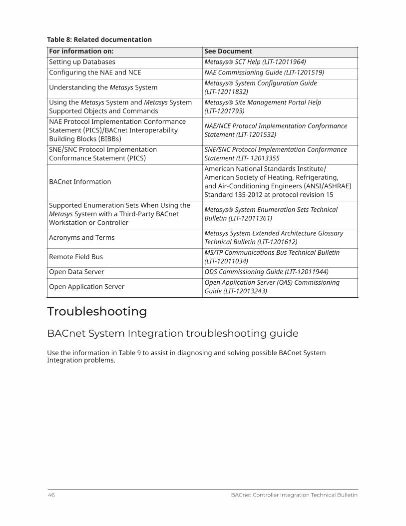
Table 8: Related documentationFor information on: See DocumentSetting up Databases Metasys® SCT Help (LIT-12011964)Configuring the NAE and NCE NAE Commissioning Guide (LIT-1201519)
Understanding the Metasys System Metasys® System Configuration Guide(LIT-12011832)
Using the Metasys System and Metasys SystemSupported Objects and Commands
Metasys® Site Management Portal Help(LIT-1201793)
NAE Protocol Implementation ConformanceStatement (PICS)/BACnet InteroperabilityBuilding Blocks (BIBBs)
NAE/NCE Protocol Implementation ConformanceStatement (LIT-1201532)
SNE/SNC Protocol ImplementationConformance Statement (PICS)
SNE/SNC Protocol Implementation ConformanceStatement (LIT- 12013355
BACnet Information
American National Standards Institute/American Society of Heating, Refrigerating,and Air-Conditioning Engineers (ANSI/ASHRAE)Standard 135-2012 at protocol revision 15
Supported Enumeration Sets When Using theMetasys System with a Third-Party BACnetWorkstation or Controller
Metasys® System Enumeration Sets TechnicalBulletin (LIT-12011361)
Acronyms and Terms Metasys System Extended Architecture GlossaryTechnical Bulletin (LIT-1201612)
Remote Field Bus MS/TP Communications Bus Technical Bulletin(LIT-12011034)
Open Data Server ODS Commissioning Guide (LIT-12011944)
Open Application Server Open Application Server (OAS) CommissioningGuide (LIT-12013243)
Troubleshooting
BACnet System Integration troubleshooting guide
Use the information in Table 9 to assist in diagnosing and solving possible BACnet SystemIntegration problems.
BACnet Controller Integration Technical Bulletin46
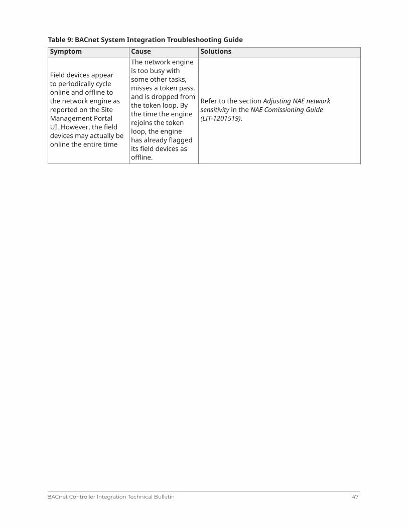
Table 9: BACnet System Integration Troubleshooting GuideSymptom Cause Solutions
Field devices appearto periodically cycleonline and offline tothe network engine asreported on the SiteManagement PortalUI. However, the fielddevices may actually beonline the entire time
The network engineis too busy withsome other tasks,misses a token pass,and is dropped fromthe token loop. Bythe time the enginerejoins the tokenloop, the enginehas already flaggedits field devices asoffline.
Refer to the section Adjusting NAE networksensitivity in the NAE Comissioning Guide(LIT-1201519).
47BACnet Controller Integration Technical Bulletin
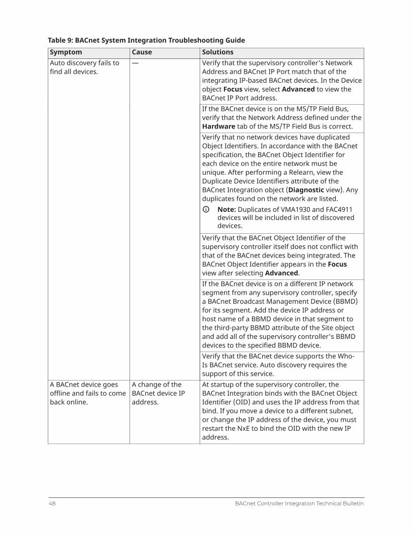
Table 9: BACnet System Integration Troubleshooting GuideSymptom Cause Solutions
Verify that the supervisory controller's NetworkAddress and BACnet IP Port match that of theintegrating IP-based BACnet devices. In the Deviceobject Focus view, select Advanced to view theBACnet IP Port address.If the BACnet device is on the MS/TP Field Bus,verify that the Network Address defined under theHardware tab of the MS/TP Field Bus is correct.Verify that no network devices have duplicatedObject Identifiers. In accordance with the BACnetspecification, the BACnet Object Identifier foreach device on the entire network must beunique. After performing a Relearn, view theDuplicate Device Identifiers attribute of theBACnet Integration object (Diagnostic view). Anyduplicates found on the network are listed.
Note: Duplicates of VMA1930 and FAC4911devices will be included in list of discovereddevices.
Verify that the BACnet Object Identifier of thesupervisory controller itself does not conflict withthat of the BACnet devices being integrated. TheBACnet Object Identifier appears in the Focusview after selecting Advanced.If the BACnet device is on a different IP networksegment from any supervisory controller, specifya BACnet Broadcast Management Device (BBMD)for its segment. Add the device IP address orhost name of a BBMD device in that segment tothe third-party BBMD attribute of the Site objectand add all of the supervisory controller's BBMDdevices to the specified BBMD device.
Auto discovery fails tofind all devices.
—
Verify that the BACnet device supports the Who-Is BACnet service. Auto discovery requires thesupport of this service.
A BACnet device goesoffline and fails to comeback online.
A change of theBACnet device IPaddress.
At startup of the supervisory controller, theBACnet Integration binds with the BACnet ObjectIdentifier (OID) and uses the IP address from thatbind. If you move a device to a different subnet,or change the IP address of the device, you mustrestart the NxE to bind the OID with the new IPaddress.
BACnet Controller Integration Technical Bulletin48

Table 9: BACnet System Integration Troubleshooting GuideSymptom Cause SolutionsBACnet Trend Logscannot be discovered.
The third-partyTrend Log objectdoes not supportBACnet LoggingType (property197) and returnsan Unknown_Property errorwhen read.
Manually add the third-party Trend Log objectto show the trend log attributes, and display theviews and log data graph properly. See Adding aTrend Extension.
Attempts to write stringattributes (such asDescription) or if alarmacknowledgments fromthe SMP UI are not seenat the BACnet device.
Encoding type maybe incorrect.
Verify that the BACnet Encoding Type specifiedin the Site matches the encoding that the BACnetdevices are using: ANSI X3.4 (US_ASCII), ISO 10646(UCS-20), or Microsoft DBCS Code Page 932.
Note: The UTF-8 BACnet Encoding Typeis also compatible with ASCII as long asextended characters (for example, Ç, ä, ╣,and ß) are not used with ASCII devices.
Time sync or UTC timesync messages are notaccepted.
— The network engine accepts BACnet time syncmessages only if no Simple Network TimeProtocol (SNTP) server is defined for that networkengine. If the device is a Site Director, do notenable (leave blank) the Site Time Serversattribute of the Site object.
or
If the device is not a Site Director, do not enable(leave blank) the Device Time Servers attribute ofthe Site object.
or
If the Time sync or UTC time sync message doesnot contain a specific time as required by BACnet(for example, message has wild card values), it isnot accepted.
Product warrantyThis product is covered by a limited warranty, details of which can be found atwww.johnsoncontrols.com/buildingswarranty.
Software termsUse of the software that is in (or constitutes) this product, or access to the cloud, orhosted services applicable to this product, if any, is subject to applicable terms set forth at
49BACnet Controller Integration Technical Bulletin
www.johnsoncontrols.com/techterms. Your use of this product constitutes an agreement to suchterms.
PatentsPatents: http://jcipat.com
Single point of contact
APAC Europe NA/SAJOHNSON CONTROLS
C/O CONTROLS PRODUCT MANAGEMENT
NO. 32 CHANGJIJANG RD NEW DISTRICT
WUXI JIANGSU PROVINCE 214028
CHINA
JOHNSON CONTROLS
WESTENDHOF 3
45143 ESSEN
GERMANY
JOHNSON CONTROLS
507 E MICHIGAN ST
MILWAUKEE WI 53202
USA
For more contact information, refer to www.johnsoncontrols.com/locations.
© 2019 Johnson Controls. All rights reserved. All specifications and other information shown were current as of documentrevision and are subject to change without notice.