BACnet® and Modbus Integration to Ascend™ Air-Cooled ...
56
SAFETY WARNING Only qualified personnel should install and service the equipment. The installation, starting up, and servicing of heating, ventilating, and air-conditioning equipment can be hazardous and requires specific knowledge and training. Improperly installed, adjusted or altered equipment by an unqualified person could result in death or serious injury. When working on the equipment, observe all precautions in the literature and on the tags, stickers, and labels that are attached to the equipment. April 2021 BAS-SVP045B-EN Integration Guide BACnet®® and Modbus Integration to Ascend™ Air-Cooled Chiller Model ACR with Symbio™ 800 Controls
Transcript of BACnet® and Modbus Integration to Ascend™ Air-Cooled ...

SSAAFFEETTYY WWAARRNNIINNGGOnly qualified personnel should install and service the equipment. The installation, starting up, and servicing of heating, ventilating, and air-conditioningequipment can be hazardous and requires specific knowledge and training. Improperly installed, adjusted or altered equipment by an unqualified personcould result in death or serious injury. When working on the equipment, observe all precautions in the literature and on the tags, stickers, and labels thatare attached to the equipment.
April 2021 BBAASS--SSVVPP004455BB--EENN
Integration Guide
BACnet®® and Modbus Integration to Ascend™ Air-Cooled Chiller Model ACRwith Symbio™ 800 Controls

©2021 Trane BAS-SVP045B-EN
IntroductionRead this manual thoroughly before operating or servicing this unit.
Warnings, Cautions, and NoticesSafety advisories appear throughout this manual as required. Your personal safety and theproper operation of this machine depend upon the strict observance of these precautions.
The three types of advisories are defined as follows:
WARNINGIndicates a potentially hazardous situation which, if not avoided, could result indeath or serious injury.
CAUTIONIndicates a potentially hazardous situation which, if not avoided, could result inminor or moderate injury. It could also be used to alert against unsafe practices.
NOTICEIndicates a situation that could result in equipment or property-damage onlyaccidents.
Important Environmental ConcernsScientific research has shown that certain man-made chemicals can affect the earth’s naturallyoccurring stratospheric ozone layer when released to the atmosphere. In particular, several of theidentified chemicals that may affect the ozone layer are refrigerants that contain Chlorine,Fluorine and Carbon (CFCs) and those containing Hydrogen, Chlorine, Fluorine and Carbon(HCFCs). Not all refrigerants containing these compounds have the same potential impact to theenvironment. Trane advocates the responsible handling of all refrigerants-including industryreplacements for CFCs and HCFCs such as saturated or unsaturated HFCs and HCFCs.
Important Responsible Refrigerant PracticesTrane believes that responsible refrigerant practices are important to the environment, ourcustomers, and the air conditioning industry. All technicians who handle refrigerants must becertified according to local rules. For the USA, the Federal Clean Air Act (Section 608) sets forththe requirements for handling, reclaiming, recovering and recycling of certain refrigerants andthe equipment that is used in these service procedures. In addition, some states or municipalitiesmay have additional requirements that must also be adhered to for responsible management ofrefrigerants. Know the applicable laws and follow them.
WWAARRNNIINNGGPPrrooppeerr FFiieelldd WWiirriinngg aanndd GGrroouunnddiinngg RReeqquuiirreedd!!FFaaiilluurree ttoo ffoollllooww ccooddee ccoouulldd rreessuulltt iinn ddeeaatthh oorr sseerriioouuss iinnjjuurryy..AAllll ffiieelldd wwiirriinngg MMUUSSTT bbee ppeerrffoorrmmeedd bbyy qquuaalliiffiieedd ppeerrssoonnnneell.. IImmpprrooppeerrllyy iinnssttaalllleedd aannddggrroouunnddeedd ffiieelldd wwiirriinngg ppoosseess FFIIRREE aanndd EELLEECCTTRROOCCUUTTIIOONN hhaazzaarrddss.. TToo aavvooiidd tthheessee hhaazzaarrddss,,yyoouu MMUUSSTT ffoollllooww rreeqquuiirreemmeennttss ffoorr ffiieelldd wwiirriinngg iinnssttaallllaattiioonn aanndd ggrroouunnddiinngg aass ddeessccrriibbeedd iinnNNEECC aanndd yyoouurr llooccaall//ssttaattee//nnaattiioonnaall eelleeccttrriiccaall ccooddeess..

BAS-SVP045B-EN 3
WWAARRNNIINNGGPPeerrssoonnaall PPrrootteeccttiivvee EEqquuiippmmeenntt ((PPPPEE)) RReeqquuiirreedd!!FFaaiilluurree ttoo wweeaarr pprrooppeerr PPPPEE ffoorr tthhee jjoobb bbeeiinngg uunnddeerrttaakkeenn ccoouulldd rreessuulltt iinn ddeeaatthh oorr sseerriioouussiinnjjuurryy..TTeecchhnniicciiaannss,, iinn oorrddeerr ttoo pprrootteecctt tthheemmsseellvveess ffrroomm ppootteennttiiaall eelleeccttrriiccaall,, mmeecchhaanniiccaall,, aannddcchheemmiiccaall hhaazzaarrddss,, MMUUSSTT ffoollllooww pprreeccaauuttiioonnss iinn tthhiiss mmaannuuaall aanndd oonn tthhee ttaaggss,, ssttiicckkeerrss,, aannddllaabbeellss,, aass wweellll aass tthhee iinnssttrruuccttiioonnss bbeellooww::
•• BBeeffoorree iinnssttaalllliinngg//sseerrvviicciinngg tthhiiss uunniitt,, tteecchhnniicciiaannss MMUUSSTT ppuutt oonn aallll PPPPEE rreeqquuiirreedd ffoorrtthhee wwoorrkk bbeeiinngg uunnddeerrttaakkeenn ((EExxaammpplleess;; ccuutt rreessiissttaanntt gglloovveess//sslleeeevveess,, bbuuttyyll gglloovveess,,ssaaffeettyy ggllaasssseess,, hhaarrdd hhaatt//bbuummpp ccaapp,, ffaallll pprrootteeccttiioonn,, eelleeccttrriiccaall PPPPEE aanndd aarrcc ffllaasshhccllootthhiinngg)).. AALLWWAAYYSS rreeffeerr ttoo aapppprroopprriiaattee SSaaffeettyy DDaattaa SShheeeettss ((SSDDSS)) aanndd OOSSHHAAgguuiiddeelliinneess ffoorr pprrooppeerr PPPPEE..
•• WWhheenn wwoorrkkiinngg wwiitthh oorr aarroouunndd hhaazzaarrddoouuss cchheemmiiccaallss,, AALLWWAAYYSS rreeffeerr ttoo tthheeaapppprroopprriiaattee SSDDSS aanndd OOSSHHAA//GGHHSS ((GGlloobbaall HHaarrmmoonniizzeedd SSyysstteemm ooff CCllaassssiiffiiccaattiioonn aannddLLaabbeelllliinngg ooff CChheemmiiccaallss)) gguuiiddeelliinneess ffoorr iinnffoorrmmaattiioonn oonn aalllloowwaabbllee ppeerrssoonnaall eexxppoossuurreelleevveellss,, pprrooppeerr rreessppiirraattoorryy pprrootteeccttiioonn aanndd hhaannddlliinngg iinnssttrruuccttiioonnss..
•• IIff tthheerree iiss aa rriisskk ooff eenneerrggiizzeedd eelleeccttrriiccaall ccoonnttaacctt,, aarrcc,, oorr ffllaasshh,, tteecchhnniicciiaannss MMUUSSTT ppuuttoonn aallll PPPPEE iinn aaccccoorrddaannccee wwiitthh OOSSHHAA,, NNFFPPAA 7700EE,, oorr ootthheerr ccoouunnttrryy--ssppeecciiffiiccrreeqquuiirreemmeennttss ffoorr aarrcc ffllaasshh pprrootteeccttiioonn,, PPRRIIOORR ttoo sseerrvviicciinngg tthhee uunniitt.. NNEEVVEERR PPEERRFFOORRMMAANNYY SSWWIITTCCHHIINNGG,, DDIISSCCOONNNNEECCTTIINNGG,, OORR VVOOLLTTAAGGEE TTEESSTTIINNGG WWIITTHHOOUUTT PPRROOPPEERREELLEECCTTRRIICCAALL PPPPEE AANNDD AARRCC FFLLAASSHH CCLLOOTTHHIINNGG.. EENNSSUURREE EELLEECCTTRRIICCAALL MMEETTEERRSS AANNDDEEQQUUIIPPMMEENNTT AARREE PPRROOPPEERRLLYY RRAATTEEDD FFOORR IINNTTEENNDDEEDD VVOOLLTTAAGGEE..
WWAARRNNIINNGGFFoollllooww EEHHSS PPoolliicciieess!!FFaaiilluurree ttoo ffoollllooww iinnssttrruuccttiioonnss bbeellooww ccoouulldd rreessuulltt iinn ddeeaatthh oorr sseerriioouuss iinnjjuurryy..
•• AAllll TTrraannee ppeerrssoonnnneell mmuusstt ffoollllooww tthhee ccoommppaannyy’’ss EEnnvviirroonnmmeennttaall,, HHeeaalltthh aanndd SSaaffeettyy((EEHHSS)) ppoolliicciieess wwhheenn ppeerrffoorrmmiinngg wwoorrkk ssuucchh aass hhoott wwoorrkk,, eelleeccttrriiccaall,, ffaallll pprrootteeccttiioonn,,lloocckkoouutt//ttaaggoouutt,, rreeffrriiggeerraanntt hhaannddlliinngg,, eettcc.. WWhheerree llooccaall rreegguullaattiioonnss aarree mmoorreessttrriinnggeenntt tthhaann tthheessee ppoolliicciieess,, tthhoossee rreegguullaattiioonnss ssuuppeerrsseeddee tthheessee ppoolliicciieess..
•• NNoonn--TTrraannee ppeerrssoonnnneell sshhoouulldd aallwwaayyss ffoollllooww llooccaall rreegguullaattiioonnss..
CopyrightThis document and the information in it are the property of Trane, and may not be used orreproduced in whole or in part without written permission. Trane reserves the right to revise thispublication at any time, and to make changes to its content without obligation to notify anyperson of such revision or change.
TrademarksAll trademarks referenced in this document are the trademarks of their respective owners.
4 BAS-SVP045B-EN
Overview . . . . . . . . . . . . . . . . . . . . . . . . . . . . . . . . . . . . . . . . . . . . . . . . . . . . . . . . . . . . . . . . . . . . . . 5Purpose. . . . . . . . . . . . . . . . . . . . . . . . . . . . . . . . . . . . . . . . . . . . . . . . . . . . . . . . . . . . . . . . . . . . . 5
Symbio 800 Controller Overview . . . . . . . . . . . . . . . . . . . . . . . . . . . . . . . . . . . . . . . . . . . . . . 5
Communication Options . . . . . . . . . . . . . . . . . . . . . . . . . . . . . . . . . . . . . . . . . . . . . . . . . . . . . 5
Units of Measure . . . . . . . . . . . . . . . . . . . . . . . . . . . . . . . . . . . . . . . . . . . . . . . . . . . . . . . . . . . . 5
Communication Setup and Configuration . . . . . . . . . . . . . . . . . . . . . . . . . . . . . . . . . . . . . 6Service Tool for Symbio™ 800 Configuration . . . . . . . . . . . . . . . . . . . . . . . . . . . . . . . . . . 6
Connecting to the Symbio™ 800 Web Interface. . . . . . . . . . . . . . . . . . . . . . . . . . . . . . . . . 6
BACnet Protocol Configuration . . . . . . . . . . . . . . . . . . . . . . . . . . . . . . . . . . . . . . . . . . . . . . . . 8BACnet TP Protocol Settings . . . . . . . . . . . . . . . . . . . . . . . . . . . . . . . . . . . . . . . . . . . . . . . . . . 8
BACnet/IP (Ethernet or Wi-Fi connectivity) . . . . . . . . . . . . . . . . . . . . . . . . . . . . . . . . . . . . . 9Manually Change Symbio™ 800 BACnet Device ID . . . . . . . . . . . . . . . . . . . . . . . . . 12Air-Fi® Wireless. . . . . . . . . . . . . . . . . . . . . . . . . . . . . . . . . . . . . . . . . . . . . . . . . . . . . . . . . 14
BACnet Points List . . . . . . . . . . . . . . . . . . . . . . . . . . . . . . . . . . . . . . . . . . . . . . . . . . . . . . . . . . . . 15Object Naming Conventions . . . . . . . . . . . . . . . . . . . . . . . . . . . . . . . . . . . . . . . . . . . . . . . . . 15
Object Data Points and Diagnostic Data Points . . . . . . . . . . . . . . . . . . . . . . . . . . . . . . . . 15ACRB 150–300 Tons Data Points . . . . . . . . . . . . . . . . . . . . . . . . . . . . . . . . . . . . . . . . . . 16ACRB 350–500 Tons Data Points . . . . . . . . . . . . . . . . . . . . . . . . . . . . . . . . . . . . . . . . . . 21
Recycled Points. . . . . . . . . . . . . . . . . . . . . . . . . . . . . . . . . . . . . . . . . . . . . . . . . . . . . . . . . . . . . 28
Modbus Protocol Configuration . . . . . . . . . . . . . . . . . . . . . . . . . . . . . . . . . . . . . . . . . . . . . . 31Modbus Protocol Settings . . . . . . . . . . . . . . . . . . . . . . . . . . . . . . . . . . . . . . . . . . . . . . . . . . . 31
Modbus Wiring . . . . . . . . . . . . . . . . . . . . . . . . . . . . . . . . . . . . . . . . . . . . . . . . . . . . . . . . . . . . . 32
Modbus TCP (Ethernet). . . . . . . . . . . . . . . . . . . . . . . . . . . . . . . . . . . . . . . . . . . . . . . . . . . . . . 32
Modbus Points List . . . . . . . . . . . . . . . . . . . . . . . . . . . . . . . . . . . . . . . . . . . . . . . . . . . . . . . . . . . 34Object Naming Conventions . . . . . . . . . . . . . . . . . . . . . . . . . . . . . . . . . . . . . . . . . . . . . . . . . 34
Object Data Points and Diagnostic Data Points . . . . . . . . . . . . . . . . . . . . . . . . . . . . . . . . 34ACRB 150–300 Tons Data Points . . . . . . . . . . . . . . . . . . . . . . . . . . . . . . . . . . . . . . . . . . 34ACRB 350–500 Tons Data Points . . . . . . . . . . . . . . . . . . . . . . . . . . . . . . . . . . . . . . . . . . 41
Recycled Points. . . . . . . . . . . . . . . . . . . . . . . . . . . . . . . . . . . . . . . . . . . . . . . . . . . . . . . . . . . . . 48
Arbitration . . . . . . . . . . . . . . . . . . . . . . . . . . . . . . . . . . . . . . . . . . . . . . . . . . . . . . . . . . . . . . . . . . .A–1
Symbio™ 800 Controller Display . . . . . . . . . . . . . . . . . . . . . . . . . . . . . . . . . . . . . . . . . . . .B–1
Table of Contents

BAS-SVP045B-EN 5
OverviewPurpose
The purpose of this document is to provide instructions for integrating the Symbio™ 800controller into Non-Trane building automation systems. This document is targeted to systemintegrators and controls contractors.
Symbio 800 Controller OverviewThe Trane Chiller includes the Symbio 800 controller. The controller has been installed,programmed, wired, commissioned, and tested in the factory prior to shipment. While somesensors and end devices are normally wired in the field, nearly all other wiring is factory-provided. Power for the controller is provided and connected from within the chiller controlpanel.
The chiller and associated controller can be applied as standalone or as part of a buildingautomation system.
NNoottee:: For communicating applications to third-party control systems, network communicationwiring must be provided by others.
Communication OptionsThe Symbio™ 800 controller supports the following communication protocol options forintegration to either Trane or Non-Trane control systems:
• BACnet TP
• BACnet Zigbee (Air-Fi)®• BACnet/IP
– Ethernet
– Wi-Fi
• Modbus RTU
• Modbus TCP
• LonTalk
For information pertaining to the integration of the Symbio™ 800 controller using either Modbusor LonTalk communication, refer to the integration guides specific to those applications.
Units of MeasureThe communicated data of the Symbio™ 800 controller will be passed in the factory-configuredunits of measure, either inch-pound (I-P) or the International System of Units (SI). The units ofmeasure are selected as part of the unit order (the default selection is normally I-P). Should theunits of measure need to be changed in the field, contact your local Trane representative.
The Symbio 800 controller provides a browser-based user interface for USB connection to thecontroller. One of the tools provided with that interface allows the user to change and customizethe Data Display Units Preferences.
IImmppoorrttaanntt:: These adjustable settings are applied only to the units of measured displayed in theweb interface, not the communicated interface.
Regardless of the communicated (system) units of measure, the user may change the displayedunits of measure on their smart device. These user preference units of measure are independentof the communicated units.

6 BAS-SVP045B-EN
Communication Setup and ConfigurationThe Symbio™ 800 controller can be factory ordered with a specific protocol configuration androtary address setting. If communication options were not specified, the Symbio™ 800 controllerwill be setup for BACnet TP communications at 76,800 bps with a rotary address setting of 000.
Figure 1. Symbio™™ 800 rotary address and service tool port
Service Tool for Symbio™™ 800 ConfigurationThe service tool used to modify the Symbio™ 800 controller is a standard web browser. TheSymbio™ 800 webpage is accessed by using a standard USB type A/B cable. Connect the USBcable between a laptop and the service tool port on the Symbio™ 800 controller (shown in Figure1, p. 6).
Connecting to the Symbio™™ 800 Web Interface1. Connect a laptop to the Symbio™ 800 controller using a USB cable.
2. On the laptop, open a web browser to http://198.80.18.1/
3. When the Symbio™ 800 page displays, click LLoogg IInn.

BAS-SVP045B-EN 7
Figure 2. Symbio™™ 800 log in screen
NNoottee:: The Symbio™ 800 web interface can only be viewed using the USB connection. Ethernetport 1 and Ethernet port 2 will not allow access to the Symbio™ web server to meet ITsecurity requirements.
CCoommmmuunniiccaattiioonn SSeettuupp aanndd CCoonnffiigguurraattiioonn

8 BAS-SVP045B-EN
BACnet Protocol ConfigurationTo access the Symbio™ 800 Protocol Configuration page:
1. Connect to the Symbio™ 800 web interface.
2. On the left-hand navigation, click IInnssttaallllaattiioonn.
3. Click IIddeennttiiffiiccaattiioonn aanndd CCoommmmuunniiccaattiioonnss.
Figure 3. Identification and Communications
4. Click the PPrroottooccooll CCoonnffiigguurraattiioonn tab.
Figure 4. Protocol Configuration
5. Click EEddiitt to change the Protocol Configuration settings. See the sections below for details onediting BACnet TP, BACnet IP, and BACnet Air-Fi protocols.
BACnet TP Protocol SettingsThe rotary address on the Symbio™ 800 controller sets the BACnet TP MAC address. EachBACnet TP device on the same TP link must have a unique MAC address. The valid range ofBACnet TP MAC addresses for the Symbio™ 800 is: 000011––112277.
IImmppoorrttaanntt:: The Symbio™ 800 controller will disable BACnet TP communications if the rotaryaddress is 000!
Changing the rotary address will immediately take affect and does NOT require a power cycle to
BAS-SVP045B-EN 9
the Symbio™ 800 controller.
The rotary address also sets the BACnet Device ID which gives a range of 11--112277.. All BACnetdevices must have a unique BACnet Device ID. The Symbio™ 800 BACnet Device ID can also bemanually changed using a web browser, the Tracer SC+ system controller, or Tracer TU.
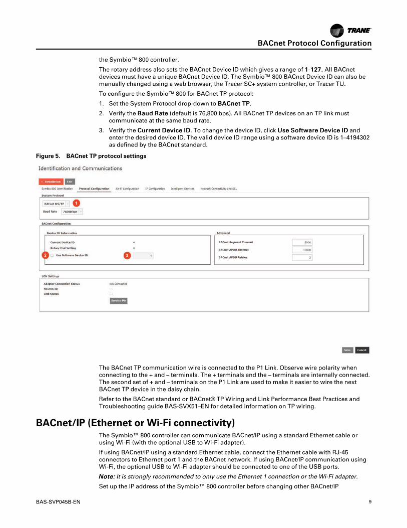
To configure the Symbio™ 800 for BACnet TP protocol:
1. Set the System Protocol drop-down to BBAACCnneett TTPP.
2. Verify the BBaauudd RRaattee (default is 76,800 bps). All BACnet TP devices on an TP link mustcommunicate at the same baud rate.
3. Verify the CCuurrrreenntt DDeevviiccee IIDD. To change the device ID, click UUssee SSooffttwwaarree DDeevviiccee IIDD andenter the desired device ID. The valid device ID range using a software device ID is 1–4194302as defined by the BACnet standard.
Figure 5. BACnet TP protocol settings
The BACnet TP communication wire is connected to the P1 Link. Observe wire polarity whenconnecting to the + and – terminals. The + terminals and the – terminals are internally connected.The second set of + and – terminals on the P1 Link are used to make it easier to wire the nextBACnet TP device in the daisy chain.
Refer to the BACnet standard or BACnet® TP Wiring and Link Performance Best Practices andTroubleshooting guide BAS-SVX51–EN for detailed information on TP wiring.
BACnet/IP (Ethernet or Wi-Fi connectivity)The Symbio™ 800 controller can communicate BACnet/IP using a standard Ethernet cable orusing Wi-Fi (with the optional USB to Wi-Fi adapter).
If using BACnet/IP using a standard Ethernet cable, connect the Ethernet cable with RJ-45connectors to Ethernet port 1 and the BACnet network. If using BACnet/IP communication usingWi-Fi, the optional USB to Wi-Fi adapter should be connected to one of the USB ports.
NNoottee:: It is strongly recommended to only use the Ethernet 1 connection or the Wi-Fi adapter.
Set up the IP address of the Symbio™ 800 controller before changing other BACnet/IP
BBAACCnneett PPrroottooccooll CCoonnffiigguurraattiioonn
10 BAS-SVP045B-EN
configuration parameters.
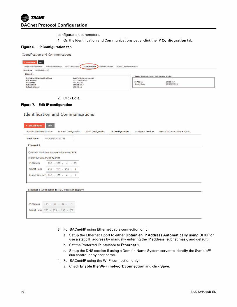
1. On the Identification and Communications page, click the IIPP CCoonnffiigguurraattiioonn tab.
Figure 6. IP Configuration tab
2. Click EEddiitt.
Figure 7. Edit IP configuration
3. For BACnet/IP using Ethernet cable connection only:
a. Setup the Ethernet 1 port to either OObbttaaiinn aann IIPP AAddddrreessss AAuuttoommaattiiccaallllyy uussiinngg DDHHCCPP oruse a static IP address by manually entering the IP address, subnet mask, and default.
b. Set the Preferred IP Interface to EEtthheerrnneett 11.
c. Setup the DNS section if using a Domain Name System server to identify the Symbio™800 controller by host name.
4. For BACnet/IP using the Wi-Fi connection only:
a. Check EEnnaabbllee tthhee WWii--FFii nneettwwoorrkk ccoonnnneeccttiioonn and click SSaavvee.
BBAACCnneett PPrroottooccooll CCoonnffiigguurraattiioonn

BAS-SVP045B-EN 11
Figure 8. Enable Wi-Fi network connection
b. Click WWii--FFii SSeettuupp.
Figure 9. Wi-Fi Setup
c. Click CClliieenntt MMooddee ((SSttaattiioonn)) to join an existing Wi-Fi access point. Click NNeexxtt.
d. Select the Wi-Fi network or type the SSID of the hidden access point. Click NNeexxtt.
e. Enter the security parameters for the chosen access point. Contact the local IT
BBAACCnneett PPrroottooccooll CCoonnffiigguurraattiioonn
12 BAS-SVP045B-EN
administrator of the chosen access point for security parameters.
f. Click FFiinniisshh and verify connectivity to the access point.
g. Set the Preferred IP Interface to WWii--FFii NNeettwwoorrkk.
h. Setup the DNS section if using a Domain Name System server to identify the Symbio™800 controller by host name.
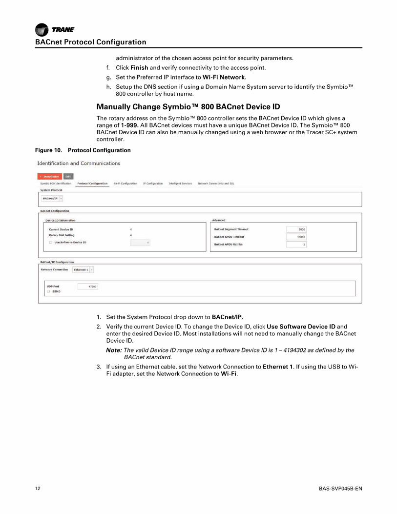
Manually Change Symbio™™ 800 BACnet Device IDThe rotary address on the Symbio™ 800 controller sets the BACnet Device ID which gives arange of 11--999999.. All BACnet devices must have a unique BACnet Device ID. The Symbio™ 800BACnet Device ID can also be manually changed using a web browser or the Tracer SC+ systemcontroller.
Figure 10. Protocol Configuration
1. Set the System Protocol drop down to BBAACCnneett//IIPP.
2. Verify the current Device ID. To change the Device ID, click UUssee SSooffttwwaarree DDeevviiccee IIDD andenter the desired Device ID. Most installations will not need to manually change the BACnetDevice ID.
NNoottee:: The valid Device ID range using a software Device ID is 1 – 4194302 as defined by theBACnet standard.
3. If using an Ethernet cable, set the Network Connection to EEtthheerrnneett 11. If using the USB to Wi-Fi adapter, set the Network Connection to WWii--FFii.
BBAACCnneett PPrroottooccooll CCoonnffiigguurraattiioonn

BAS-SVP045B-EN 13
Figure 11. Network Connection
4. Set the UDP Port to match the port number used by the BACnet/IP network. The default is47808.
5. Check the BBMD checkbox only if the Symbio™ 800 controller is the only BACnet/IP device onthe IP subnet.
a. If a change to the BBMD checkbox was made, click SSaavvee and refresh the web browser. IfBBMD functionality is enabled, the BDT setup button displays.
Figure 12. BDT setup
b. If BBMD functionality is enabled, click BBDDTT SSeettuupp to set up the BACnet Distribution Table(BDT). The IP addresses of all BBMDs in the BACnet intranetwork should be in the BDT.and all BBMDs should have the same BDT entries.
IImmppoorrttaanntt:: A strong knowledge of BACnet networking is needed to properly setup BBMDand BDT functionality.
For additional information on BBMDs and BDTs, refer to the BACnet specification or yourlocal Trane office.
BBAACCnneett PPrroottooccooll CCoonnffiigguurraattiioonn
14 BAS-SVP045B-EN
Air-Fi®®WirelessAir-Fi Wireless – Conforms to ANSI/ASHRAE Standard 135-2016 (BACnet®/ZigBee®1). Air-FiWireless provides reliable and secure, and location-flexible communication between equipmentcontrols, sensors, and service tools to the system controller.
Air-Fi networks will be setup by a Trane technician. Integration to a Symbio™ 800 controllersetup for Air-Fi communications uses BACnet/IP communication through a Tracer SC+ systemcontroller. Contact your local Trane office for additional information if the Symbio™ 800controller is setup for Air-Fi Wireless.
BBAACCnneett PPrroottooccooll CCoonnffiigguurraattiioonn
1. ZigBee is a registered trademark of the ZigBee Alliance.

BAS-SVP045B-EN 15
BACnet Points ListObject Naming Conventions
The communicated points for the Symbio™ controllers are generally named according to theirfunction. While many of the points are read-only, others include both read and write capability.The established naming convention helps to identify the capabilities of each point. For mostpoints, the suffix identifies the capability according to the following definition.
While there are some exceptions, the majority of the points have been defined according to theseguidelines.
Suffix Description
Status Points with the Status suffix are defined as read-only. The status point reports thevalue being used by the controller.
Local Points with the Local suffix are defined as read-only. The local point reports valuesassociated with controller sensors, both wired and wireless. The local value mayor may not be actively used by the controller, depending on the presence orabsence of a communicated value (BAS). When both a local and communicatedvalue exist, the communicated value is used.
Active Points with the Active suffix are defined as read-only. Points designated as activeare normally the result of the arbitration between a communicated value (BAS)and at least one value local to the equipment, such as a sensor or defaultsetpoint. The active point reports the value being used by the controller.
Setpoint Points with the Setpoint suffix are defined as either read-only or read/write. ForBACnet, the binary input, analog input and multi-state input points are all read-only. These setpoints report the value currently in use by the controller.The analog value, binary value and multi-state value points are all read/write.These points are provided for use by the building automation system (BAS).When used, these points are written internally to arbitration logic. This definesthe interaction with hardwired points, editable software configuration points andthe relinquish default value/state. Refer to the Appendix for additionalinformation.
Input Points with the Input suffix are defined as read-only. These points normally reflectthe status of a sensor input, either hardwired or communicating wirelessly (Air-Fi). However, the input point reflects the arbitrated result of the controller sensorinput and a communicated value, if present. When both a controller sensor andcommunicated value exist, the controller will use and report the communicatedvalue.
Arbitrator Points with the “Arbitrator” suffix are to be used as read-only. The arbitratorprioritizes inputs from communicating points, hardwired points and storeddefaults points. The priority array of the arbitration point displays each of thevalues provided, including the active status, indicating which of the input sourcesis being used. Refer to the Appendix for additional information.
BAS Points with the BAS suffix are defined as read/write. These points are provided foruse by the building automation system (BAS). When used, these points arewritten to arbitration logic. This defines the interaction with hardwired points,editable software configuration points and the relinquished default value/state.Refer to the Appendix for additional information.
Command Points with the Command suffix are defined as read/write. These points arewritten to change the default behavior of the controller. Once written, these pointvalues may be persisted.
Request Points with the Request suffix are defined as read/write. These points are writtento change the operating behavior of the controller.
Object Data Points and Diagnostic Data PointsThe following tables are sorted as follows:
• Tables are listed by input/output type and sorted by object identifier. These tables provide theuser with the units type for each object type.

16 BAS-SVP045B-EN
• Tables are sorted by object name and provide a complete list of object names, types, values/ranges, and descriptions.
NNoottee:: Not all points are available to the user. The available data points are defined duringself-configuration and are dependent on the type of equipment.
ACRB 150–300 Tons Data PointsTable 1. ACRB 150–300 tons analog inputs
ObjectIdentifier
Object Name Description Units
AI-10100 Active Chilled Water Setpoint Indicates the value of the active Chilled Water Setpoint actively beingused by the chiller Degrees Fahrenheit
AI-10101 Evaporator Entering Water Temperature Indicates the current temperature of the water entering theevaporator Degrees Fahrenheit
AI-10102 Evaporator Leaving Water Temperature Indicates the current temperature of the water leaving the evaporator Degrees Fahrenheit
AI-10103 Calculated Chiller Capacity Indicates the capacity the chiller is currently using Tons of Refrigeration
AI-10104 Active Demand Limit Setpoint Indicates the demand limit setpoint value actively being used by thechiller Percent
AI-10105 Unit Power Consumption Indicates the measurement of the power being consumed by theChiller Kilowatts
AI-10106 Outdoor Air Temperature Indicates the current temperature of the outdoor air Degrees Fahrenheit
AI-10107 Evaporator Refrigerant Pressure Circuit 1 Indicates the current pressure of the refrigerant in the evaporator oncircuit 1
Pound Force perSquare Inch
AI-10108 Condenser Refrigerant Pressure Circuit 1 Indicates the current pressure of the refrigerant in the condenser oncircuit 1
Pound Force perSquare Inch
AI-10109 Differential Refrigerant Pressure Circuit 1 Indicates the pressure difference between the suction and dischargelines on circuit 1
Pound Force perSquare Inch
AI-10110Evaporator Saturated Refrigerant
Temperature Circuit 1Indicates the saturated_x000D_
refrigerant temperature of the evaporator on circuit 1 Degrees Fahrenheit
AI-10111Condenser Saturated Refrigerant
Temperature Circuit 1Indicates the saturated_x000D_
refrigerant temperature of the condenser on circuit 1 Degrees Fahrenheit
AI-10112 Evaporator Refrigerant Pressure Circuit 2 Indicates the current pressure of the refrigerant in the evaporator oncircuit 2
Pound Force perSquare Inch
AI-10113 Condenser Refrigerant Pressure Circuit 2 Indicates the current pressure of the refrigerant in the condenser oncircuit 2
Pound Force perSquare Inch
AI-10114 Differential Refrigerant Pressure Circuit 2 Indicates the pressure difference between the suction and dischargelines on circuit 2
Pound Force perSquare Inch
AI-10115Evaporator Saturated Refrigerant
Temperature Circuit 2Indicates the saturated_x000D_
refrigerant temperature of the evaporator on circuit 2 Degrees Fahrenheit
AI-10116Condenser Saturated Refrigerant
Temperature Circuit 2Indicates the saturated_x000D_
refrigerant temperature of the condenser on circuit 2 Degrees Fahrenheit
AI-10117Refrigerant Discharge Temperature -
Compressor 1AIndicates the current temperature of the refrigerant being discharged
from Compressor 1A Degrees Fahrenheit
AI-10118 Oil Pressure - Compressor 1A Indicates the pressure of the oil on the high pressure side ofCompressor 1A
Pound Force perSquare Inch
AI-10119Refrigerant Discharge Temperature -
Compressor 2AIndicates the current temperature of the refrigerant being discharged
from Compressor 2A Degrees Fahrenheit
AI-10120 Oil Pressure - Compressor 2A Indicates the pressure of the oil on the high pressure side ofCompressor 2A
Pound Force perSquare Inch
AI-10121 Air Flow Percentage Circuit 1 Indicates the approximate air flow percentage of Circuit 1 Percent
AI-10122 Air Flow Percentage Circuit 2 Indicates the approximate air flow percentage of Circuit 2 Percent
AI-10123 Starts - Compressor 1A Indicates the number of starts of Compressor 1A No Units
AI-10124 Run Time - Compressor 1A Indicates the run time of Compressor 1A, in hours Hours
AI-10125 Compressor 1A Speed Status Indicates the % of the available speed being used by Compressor 1A Percent
AI-10126 Motor Winding Temperature 1 Circuit 1 Indicates the first temperaure sensor of the windings on motor 1A Degrees Fahrenheit
AI-10127 Motor Winding Temperature 2 Circuit 1 Indicates the second temperaure sensor of the windings on motor 1A Degrees Fahrenheit
AI-10128 Drive Motor Current U RLA Compressor1A
Indicates the measurement of Line 1 current at AFD for Compressor1A in terms of % RLA Percent
AI-10129 Drive Motor Current V RLA Compressor1A
Indicates the measurement of Line 2 current at AFD for Compressor1A in terms of % RLA Percent
AI-10130 Drive Motor Current W RLA Compressor1A
Indicates the measurement of Line 3 current at AFD for Compressor1A in terms of % RLA Percent
AI-10131Drive Motor Average Current RLA
Compressor 1AIndicates the average current at AFD for Compressor 1A in terms of %
RLA Percent
BBAACCnneett PPooiinnttss LLiisstt
BAS-SVP045B-EN 17
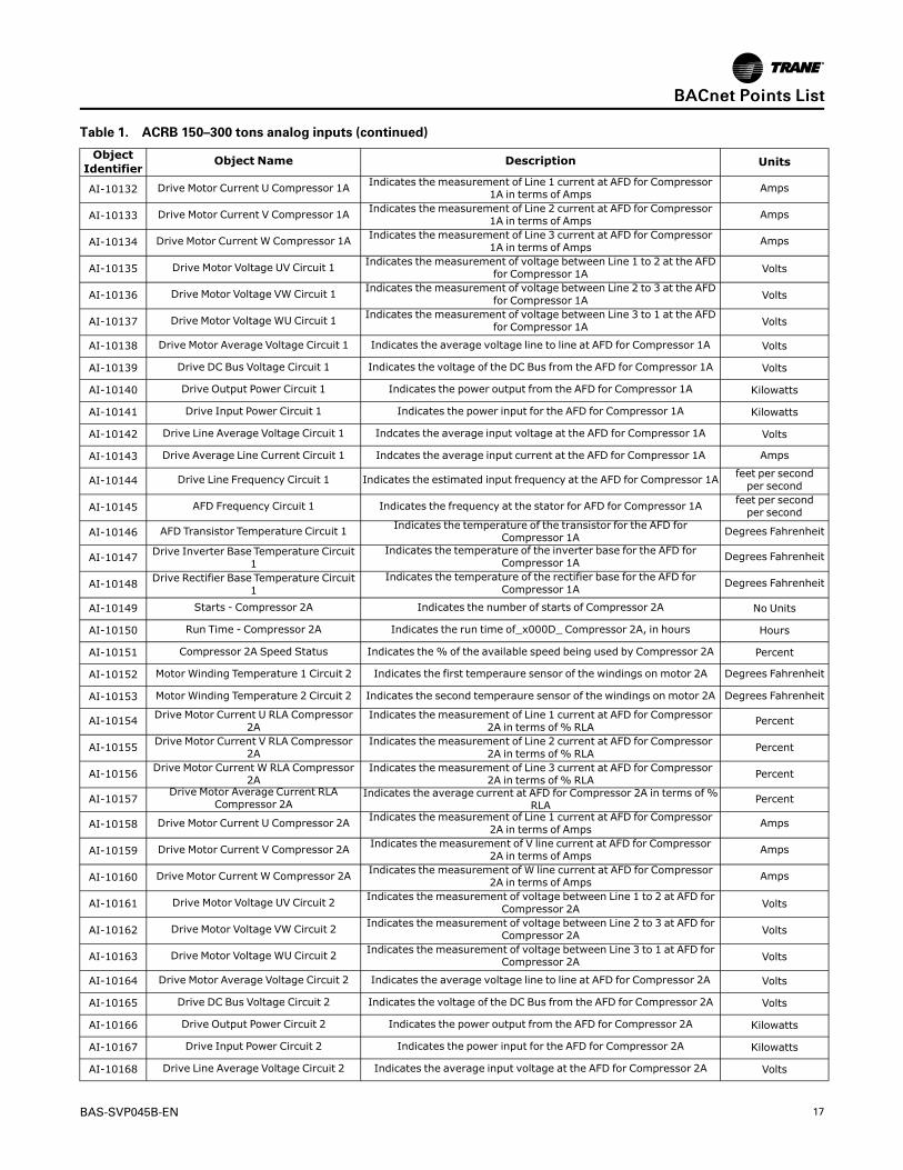
Table 1. ACRB 150–300 tons analog inputs (continued)
ObjectIdentifier
Object Name Description Units
AI-10132 Drive Motor Current U Compressor 1A Indicates the measurement of Line 1 current at AFD for Compressor1A in terms of Amps Amps
AI-10133 Drive Motor Current V Compressor 1A Indicates the measurement of Line 2 current at AFD for Compressor1A in terms of Amps Amps
AI-10134 Drive Motor Current W Compressor 1A Indicates the measurement of Line 3 current at AFD for Compressor1A in terms of Amps Amps
AI-10135 Drive Motor Voltage UV Circuit 1 Indicates the measurement of voltage between Line 1 to 2 at the AFDfor Compressor 1A Volts
AI-10136 Drive Motor Voltage VW Circuit 1 Indicates the measurement of voltage between Line 2 to 3 at the AFDfor Compressor 1A Volts
AI-10137 Drive Motor Voltage WU Circuit 1 Indicates the measurement of voltage between Line 3 to 1 at the AFDfor Compressor 1A Volts
AI-10138 Drive Motor Average Voltage Circuit 1 Indicates the average voltage line to line at AFD for Compressor 1A Volts
AI-10139 Drive DC Bus Voltage Circuit 1 Indicates the voltage of the DC Bus from the AFD for Compressor 1A Volts
AI-10140 Drive Output Power Circuit 1 Indicates the power output from the AFD for Compressor 1A Kilowatts
AI-10141 Drive Input Power Circuit 1 Indicates the power input for the AFD for Compressor 1A Kilowatts
AI-10142 Drive Line Average Voltage Circuit 1 Indcates the average input voltage at the AFD for Compressor 1A Volts
AI-10143 Drive Average Line Current Circuit 1 Indcates the average input current at the AFD for Compressor 1A Amps
AI-10144 Drive Line Frequency Circuit 1 Indicates the estimated input frequency at the AFD for Compressor 1A feet per secondper second
AI-10145 AFD Frequency Circuit 1 Indicates the frequency at the stator for AFD for Compressor 1A feet per secondper second
AI-10146 AFD Transistor Temperature Circuit 1 Indicates the temperature of the transistor for the AFD forCompressor 1A Degrees Fahrenheit
AI-10147 Drive Inverter Base Temperature Circuit1
Indicates the temperature of the inverter base for the AFD forCompressor 1A Degrees Fahrenheit
AI-10148 Drive Rectifier Base Temperature Circuit1
Indicates the temperature of the rectifier base for the AFD forCompressor 1A Degrees Fahrenheit
AI-10149 Starts - Compressor 2A Indicates the number of starts of Compressor 2A No Units
AI-10150 Run Time - Compressor 2A Indicates the run time of_x000D_ Compressor 2A, in hours Hours
AI-10151 Compressor 2A Speed Status Indicates the % of the available speed being used by Compressor 2A Percent
AI-10152 Motor Winding Temperature 1 Circuit 2 Indicates the first temperaure sensor of the windings on motor 2A Degrees Fahrenheit
AI-10153 Motor Winding Temperature 2 Circuit 2 Indicates the second temperaure sensor of the windings on motor 2A Degrees Fahrenheit
AI-10154 Drive Motor Current U RLA Compressor2A
Indicates the measurement of Line 1 current at AFD for Compressor2A in terms of % RLA Percent
AI-10155 Drive Motor Current V RLA Compressor2A
Indicates the measurement of Line 2 current at AFD for Compressor2A in terms of % RLA Percent
AI-10156 Drive Motor Current W RLA Compressor2A
Indicates the measurement of Line 3 current at AFD for Compressor2A in terms of % RLA Percent
AI-10157Drive Motor Average Current RLA
Compressor 2AIndicates the average current at AFD for Compressor 2A in terms of %
RLA Percent
AI-10158 Drive Motor Current U Compressor 2A Indicates the measurement of Line 1 current at AFD for Compressor2A in terms of Amps Amps
AI-10159 Drive Motor Current V Compressor 2A Indicates the measurement of V line current at AFD for Compressor2A in terms of Amps Amps
AI-10160 Drive Motor Current W Compressor 2A Indicates the measurement of W line current at AFD for Compressor2A in terms of Amps Amps
AI-10161 Drive Motor Voltage UV Circuit 2 Indicates the measurement of voltage between Line 1 to 2 at AFD forCompressor 2A Volts
AI-10162 Drive Motor Voltage VW Circuit 2 Indicates the measurement of voltage between Line 2 to 3 at AFD forCompressor 2A Volts
AI-10163 Drive Motor Voltage WU Circuit 2 Indicates the measurement of voltage between Line 3 to 1 at AFD forCompressor 2A Volts
AI-10164 Drive Motor Average Voltage Circuit 2 Indicates the average voltage line to line at AFD for Compressor 2A Volts
AI-10165 Drive DC Bus Voltage Circuit 2 Indicates the voltage of the DC Bus from the AFD for Compressor 2A Volts
AI-10166 Drive Output Power Circuit 2 Indicates the power output from the AFD for Compressor 2A Kilowatts
AI-10167 Drive Input Power Circuit 2 Indicates the power input for the AFD for Compressor 2A Kilowatts
AI-10168 Drive Line Average Voltage Circuit 2 Indicates the average input voltage at the AFD for Compressor 2A Volts
BBAACCnneett PPooiinnttss LLiisstt

18 BAS-SVP045B-EN
Table 1. ACRB 150–300 tons analog inputs (continued)
ObjectIdentifier
Object Name Description Units
AI-10169 Drive Average Line Current Circuit 2 Indicates the average input current at the AFD for Compressor 2A Amps
AI-10170 Drive Line Frequency Circuit 2 Indicates the estimated input frequency at the AFD for Compressor 2A feet per secondper second
AI-10171 AFD Frequency Circuit 2 Indicates the frequency at the stator for AFD for Compressor 2A feet per secondper second
AI-10172 AFD Transistor Temperature Circuit 2 Indicates the temperature of the transidtor for the AFD forCompressor 2A Degrees Fahrenheit
AI-10173 Drive Inverter Base Temperature Circuit2
Indicates the temperature of the inverter base for the AFD forCompressor 2A Degrees Fahrenheit
AI-10174 Drive Rectifier Base Temperature Circuit2
Indicates the temperature of the rectifier base for the AFD forCompressor 2A Degrees Fahrenheit
AI-10175 Number Of Circuits Indicates the number of refrigeration circuits in thechiller No Units
AI-10176 Number Of Compressors Circuit 1 Indicates the number of compressors on circuit 1 of the chiller No Units
AI-10177 Number Of Compressors Circuit 2 Indicates the number of compressors on circuit 2 ofthe chiller No Units
AI-10178 Free Cooling Capacity Indicates the% capacity of the free cooling being used Percent
AI-10179 Free Cooling Entering Water Temperature Indiactes the entering water temperature of the free cooling circuit Degrees Fahrenheit
AI-10180 Energy Consumption Lifetime Indicates the total energy consumption of the chiller (for the lifetimeof the chiller) Kilowatts hour
AI-10181 Energy Consumption Indicates the total energy consumption of the chiller (since lastaccumulation reset) Kilowatts hour
AI-10182 Unit Source IDIndicates the last diagnostic of the chiller
Separately, individual diagnostics are reported withdedicated points, variables, registers
No Units
AI-10183 Chiller Design Capacity Indicates the design capacity of chilller Tons of Refrigeration
AI-10184 Active Cool/Heat Setpoint Temperature Indicates the value of the active Chilled Water Setpoint actively beingused by the chiller Degrees Fahrenheit
AI-10185 Actual Running Capacity Indicates the measurement of the power being consumed by theChiller Percent
Table 2. ACRB 150–300 tons analog values
ObjectIdentifier
Object Name Description Units
AV-10100 BAS Chilled Water Setpoint
The value is normally provided by the BAS to send the Chilled WaterSetpoint.The value is subject to arbitration logic in the controller, in which case itmay or may not be used for control purposes
Degrees Fahrenheit
AV-10101 BAS Demand Limit Setpoint
The value is normally provided by the BAS to send the Demand LimitSetpoint.The value is subject to arbitration logic in the controller, in which case itmay or may not be used for control purposes
Percent
Table 3. ACRB 150–300 tons binary inputs
ObjectIdentifier
Object Name Description Object States
BI-10100 Run EnableIndicates that chiller is available to run or is currently
running0 = Run Not Enabled1 = Run Enabled
BI-10101 Local Setpoint Control Indicates the which setpoint is used for control purposes,Remote (BAS) or Local
0 = Remote control1 = Local control
BI-10102 Limit Mode Relay Status Indicates the status of the chiller limit relay 0 = Off1 = On
BI-10103 Chiller Running State Indicates whether the chiller is on (currently doing eithercooling) or is considered off(not currently doing cooling)
0 = Off1 = On
BI-10104 Maximum Capacity Indicates the status of the maximum capacity relay 0 = Off1 = On
BI-10105 Evaporator Water Pump Command Indicates a request from the chiller to turn on theEvaporator Water Pump
0 = Off1 = On
BI-10106 Evaporator Water Flow Status Indicates the flow of water through evaporator 0 = No Flow1 = Flow
BI-10107 Manual Override Exists Indicated a manual override is present 0 = Off1 = On
BBAACCnneett PPooiinnttss LLiisstt

BAS-SVP045B-EN 19
Table 3. ACRB 150–300 tons binary inputs (continued)
ObjectIdentifier
Object Name Description Object States
BI-10108 Emergency Stop Indicates the status of the emergency stop function of thechiller
0 = Auto1 = Emergency Stop -Manual Reset Required
BI-10109 Diagnostic Present Indicates whether diagnostic present 0 = Normal1 = In Alarm
BI-10110 Diagnostic Shutdown Present Indicates chiller is shut down due to diagnostics 0 = Normal1 = In Alarm
BI-10111 Diagnostic: Manual Reset Required Indicates when a diagnostic exists that requires manualreset
0 = Normal1 = In Alarm
BI-10112 Diagnostic: Local Manual Reset Required Indicates when a diagnostic exists that requires manualreset [Local only]
0 = Normal1 = In Alarm
BI-10113 Diagnostic Present: Information Indicates whether diagnostic present with InformationCategory
0 = Normal1 = In Alarm
BI-10114 Diagnostic Present: Advisory Indicates whether diagnostic present with WarningCategory
0 = Normal1 = In Alarm
BI-10115 Diagnostic Present: Critical Indicates whether diagnostic present with CriticalCategory
0 = Normal1 = In Alarm
BI-10116 Diagnostic Present: Service Required Indicates whether diagnostic present with ServiceRequired Category
0 = Normal1 = In Alarm
BI-10117 Compressor 1A Running Status Indicates running state fo Compressor 1A 0 = Off1 = Running
BI-10118 Compressor 2A Running Status Indicates running state fo Compressor 2A 0 = Off1 = Running
BI-10119 Free Cooling Active Indicated the free cooling mode is active 0 = Inactive1 = Active
BI-10120 External Auto Stop Status Indicates the status of the externally-wired auto/stopinput
0 = Stop1 = Auto
BI-10121 Front Panel Auto Stop Status Indicates the auto/stop status of the Front Panel 0 = Stop1 = Auto
BI-10122 Noise Reduction Request Active Indicates wherther Noise Reduction active 0 = Off1 = On
Table 4. ACRB 150–300 tons binary values
ObjectIdentifier
Object Name Description Object States
BV-10100 Reset Diagnostic Normally used by the BMS to initiate a requestto reset any controller diagnostics
0 = Normal1 = Reset
BV-10101 Noise Reduction Request BASNormally used by the BMS to command the chiller toenter a mode of operation where the noise of the unit
is reduced
0 = Normal1 = Reduce Noise
BV-10102 Chiller Auto Stop Command BASNormally used by the BMS to command the chiller tostart running if operating conditions are satisfied, or to
stop the chiller from running.
0 = Stop1 = Auto
BV-10103 Free Cooling Auto Stop CommandBAS
Normally used the BMS to command the chiller toallow free cooling mode if conditions are satisfied, or
to stop the free cooling mode from operating.
0 = Stop1 = Auto
BV-10104 Free Cooling Compressor Lockout Normally used by the BMS to lockout the Compressorwhile in free cooling mode
0 = Normal1 = Locked Out
BV-10105 Circuit 1 Lockout BASNormally used by the BMS to lockout the Circuit-1
Compressor0 = Normal
1 = Locked Out
BV-10106 Circuit 2 Lockout BASNormally used by the BMS to lockout the Circuit-2
Compressor0 = Normal
1 = Locked Out
BV-10107 Energy Consumption Reset Normally used by the BMS to reset the energyconsumption accumulated total
0 = Accumulating1 = Reset
Table 5. ACRB 150–300 tons multi-state inputs
ObjectIdentifier
Object Name Description Object States
MI-10100 Running Mode Indicates the running state of the chiller
1 = Chiller Off2 = Chiller In Start Mode3= Chiller In Run Mode
4= Chiller In Pre-Shutdown Mode5 = Chiller In Service Mode
MI-10101 Operating Mode Indicates the operating mode of the chiller
1 = Cool2 = Heat
3= Ice Making4= Free Cooling
BBAACCnneett PPooiinnttss LLiisstt
20 BAS-SVP045B-EN
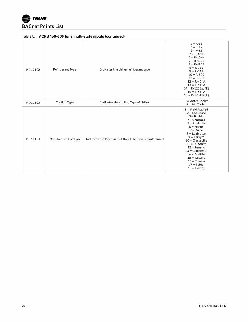
Table 5. ACRB 150–300 tons multi-state inputs (continued)
MI-10102 Refrigerant Type Indicates the chiller refrigerant type
1 = R-112 = R-123= R-224= R-1235 = R-134a6 = R-407C7 = R-410A8 = R-1139 = R-11410 = R-50011 = R-50212 = R-404A13 = R-513A
14 = R-1233zd(E)15 = R-514A
16 = R-1234ze(E)
MI-10103 Cooling Type Indicates the cooling Type of chiller 1 =Water Cooled2 = Air Cooled
MI-10104 Manufacture Location Indicates the location that the chiller was manufactured
1 = Field Applied2 = La Crosse3= Pueblo4= Charmes5 = Rushville6 = Macon7 =Waco
8 = Lexington9 = Forsyth
10 = Clarksville11 = Ft. Smith12 = Penang13 = Colchester14 = Curitiba15 = Taicang16 = Taiwan17 = Epinal18 = Golbey
BBAACCnneett PPooiinnttss LLiisstt

BAS-SVP045B-EN 21
Table 5. ACRB 150–300 tons multi-state inputs (continued)
MI-10105 Model Information [GEN2] Indicates the model information of chiller
1 = CVHF2 = CVGF3= CVHS4= RTAE5 = RTAF6 = RTHA7 = RTHB8 = RTHC9 = RTHD10 = RTWE11 = CTVD12 = CVR13 = CVHH14 = CDHH15 = VMAX16 = GVAF17 = RTWF18 = RTHF19 = RTAC20 = CVHM21 = RTAG22 = CGAF23 = RTXG24 = GVWF25 = HDWA26 = CMAC27 = IPAK28 = CXAF29 = ACSA30 = RTSF31 = HSWA32 = ACRA33 = RTEG34 = ACXA35 = CMAF
36 = ACRB Large37 = ACRB Small
MI-10106 Chiller Setpoint Source Indicates the selected setpoint source for controlpurpose
1 = BAS2 = External3 = Front Panel
Table 6. ACRB 150–300 tons multi-state values
Object Identifier Object Name Description Object States
MV-10100 BAS Chiller Mode Command Normally used by the BMS to command the chiller Mode
1 = Cool2 = Heat
3= Ice Making4= Free Cooling
ACRB 350–500 Tons Data PointsTable 7. ACRB 350–500 tons analog inputs
ObjectIdentifier
Object Name Description Units
AI-10100 Active Chilled Water Setpoint Indicates the value of the active Chilled Water Setpoint actively beingused by the chiller Degrees Fahrenheit
AI-10101 Active Demand Limit Setpoint Indicates the demand limit setpoint value actively being used by thechiller Percent
AI-10101 Active Demand Limit Setpoint Indicates the demand limit setpoint value actively being used by thechiller Percent
AI-10103 Evaporator Entering Water Temperature Indicates the current temperature of the water entering theevaporator Degrees Fahrenheit
AI-10104 Evaporator Leaving Water Temperature Indicates the current temperature of the water leaving the evaporator Degrees Fahrenheit
AI-10106 Unit Power Consumption Indicates the measurement of the power being consumed by theChiller Kilowatts
AI-10107 Outdoor Air Temperature Indicates the current temperature of the outdoor air Degrees Fahrenheit
AI-10110 Evaporator Refrigerant Pressure Circuit 1 Indicates the current pressure of the refrigerant in the evaporator oncircuit 1
Pound Force perSquare Inch
BBAACCnneett PPooiinnttss LLiisstt

22 BAS-SVP045B-EN
Table 7. ACRB 350–500 tons analog inputs (continued)
ObjectIdentifier
Object Name Description Units
AI-10111 Condenser Refrigerant Pressure Circuit 1 Indicates the current pressure of the refrigerant in the condenser oncircuit 1
Pound Force perSquare Inch
AI-10112 Differential Refrigerant Pressure Circuit 1 Indicates the pressure difference between the suction and dischargelines on circuit 1
Pound Force perSquare Inch
AI-10113Evaporator Saturated Refrigerant
Temperature Circuit 1Indicates the saturated_x000D_
refrigerant temperature of the evaporator on circuit 1 Degrees Fahrenheit
AI-10114Condenser Saturated Refrigerant
Temperature Circuit 1Indicates the saturated_x000D_
refrigerant temperature of the condenser on circuit 1 Degrees Fahrenheit
AI-10115 Evaporator Refrigerant Pressure Circuit 2 Indicates the current pressure of the refrigerant in the evaporator oncircuit 2
Pound Force perSquare Inch
AI-10116 Condenser Refrigerant Pressure Circuit 2 Indicates the current pressure of the refrigerant in the condenser oncircuit 2
Pound Force perSquare Inch
AI-10117 Differential Refrigerant Pressure Circuit 2 Indicates the pressure difference between the suction and dischargelines on circuit 2
Pound Force perSquare Inch
AI-10118Evaporator Saturated Refrigerant
Temperature Circuit 2Indicates the saturated_x000D_
refrigerant temperature of the evaporator on circuit 2 Degrees Fahrenheit
AI-10119Condenser Saturated Refrigerant
Temperature Circuit 2Indicates the saturated_x000D_
refrigerant temperature of the condenser on circuit 2 Degrees Fahrenheit
AI-10120Refrigerant Discharge Temperature -
Compressor 1AIndicates the current temperature of the refrigerant being discharged
from Compressor 1A Degrees Fahrenheit
AI-10121 High Side Oil Pressure - Compressor 1A Indicates the pressure of the oil on the high pressure side ofCompressor 1A
Pound Force perSquare Inch
AI-10122Refrigerant Discharge Temperature -
Compressor 2AIndicates the current temperature of the refrigerant being discharged
from Compressor 2A Degrees Fahrenheit
AI-10123 High Side Oil Pressure - Compressor 2A Indicates the pressure of the oil on the high pressure side ofCompressor 2A
Pound Force perSquare Inch
AI-10124 Air Flow Percentage Circuit 1 Indicates the approximate air flow percentage of Circuit 1 Percent
AI-10125 Air Flow Percentage Circuit 2 Indicates the approximate air flow percentage of Circuit 2 Percent
AI-10126 Drive Motor Average Voltage Circuit 1 Indicates the average voltage line to line at AFD for Compressor 1A Volts
AI-10127 Drive Motor Current U Circuit 1Indicates the measurement of Line 1 current at AFD for Compressor
1A in terms of Amps Amps
AI-10128 Drive Motor Current V Circuit 1Indicates the measurement of Line 2 current at AFD for Compressor
1A in terms of Amps Amps
AI-10129 Drive Motor Current W Circuit 1Indicates the measurement of Line 3 current at AFD for Compressor
1A in terms of Amps Amps
AI-10130 Drive Motor Current U RLA Circuit 1 Indicates the measurement of Line 1 current at AFD for Compressor1A in terms of % RLA Percent
AI-10131 Drive Motor Current V RLA Circuit 1 Indicates the measurement of Line 2 current at AFD for Compressor1A in terms of % RLA Percent
AI-10132 Drive Motor Current W RLA Circuit 1 Indicates the measurement of Line 3 current at AFD for Compressor1A in terms of % RLA Percent
AI-10133 Drive Motor Average Current RLA Circuit1
Indicates the average current at AFD for Compressor 1A in terms of %RLA Percent
AI-10134 Drive DC Bus Voltage Circuit 1 Indicates the voltage of the DC Bus from the AFD for Compressor 1A Volts
AI-10135 Drive Output Power Circuit 1 Indicates the power output from the AFD for Compressor 1A Kilowatts
AI-10136 AFD Transistor Temperature Circuit 1 Indicates the temperature of the transistor for the AFD forCompressor 1A Degrees Fahrenheit
AI-10137 Motor Winding Temperature 1 Circuit 1 Indicates the first temperaure sensor of the windings on motor 1A Degrees Fahrenheit
AI-10138 Motor Winding Temperature 2 Circuit 1 Indicates the second temperaure sensor of the windings on motor 1A Degrees Fahrenheit
AI-10139 Drive Motor Average Voltage Circuit 2 Indicates the average voltage line to line at AFD for Compressor 2A Volts
AI-10140 Drive Motor Current U Circuit 2Indicates the measurement of Line 1 current at AFD for Compressor
2A in terms of Amps Amps
AI-10141 Drive Motor Current V Circuit 2Indicates the measurement of V line current at AFD for Compressor
2A in terms of Amps Amps
AI-10142 Drive Motor Current W Circuit 2Indicates the measurement of W line current at AFD for Compressor
2A in terms of Amps Amps
AI-10143 Drive Motor Current U RLA Circuit 2 Indicates the measurement of Line 1 current at AFD for Compressor2A in terms of % RLA Percent
AI-10144 Drive Motor Current V RLA Circuit 2 Indicates the measurement of Line 2 current at AFD for Compressor2A in terms of % RLA Percent
AI-10145 Drive Motor Current W RLA Circuit 2 Indicates the measurement of Line 3 current at AFD for Compressor2A in terms of % RLA Percent
AI-10146 Drive Motor Average Current RLA Circuit2
Indicates the average current at AFD for Compressor 2A in terms of %RLA Percent
AI-10147 Drive DC Bus Voltage Circuit 2 Indicates the voltage of the DC Bus from the AFD for Compressor 2A Volts
AI-10148 Drive Output Power Circuit 2 Indicates the power output from the AFD for Compressor 2A Kilowatts
AI-10149 AFD Transistor Temperature Circuit 2 Indicates the temperature of the transidtor for the AFD forCompressor 2A Degrees Fahrenheit
BBAACCnneett PPooiinnttss LLiisstt

BAS-SVP045B-EN 23
Table 7. ACRB 350–500 tons analog inputs (continued)
ObjectIdentifier
Object Name Description Units
AI-10150 Motor Winding Temperature 1 Circuit 2 Indicates the first temperaure sensor of the windings on motor 2A Degrees Fahrenheit
AI-10151 Motor Winding Temperature 2 Circuit 2 Indicates the second temperaure sensor of the windings on motor 2A Degrees Fahrenheit
AI-10152 Sub Cooled Liquid Temperature Circuit 1 Indicates the sub cooled liquid temperature of circuit 1 Degrees Fahrenheit
AI-10153 Sub Cooled Liquid Temperature Circuit 2 Indicates the sub cooled liquid temperature of circuit 2 Degrees Fahrenheit
AI-10154 Evaporator Differential Water Pressure Indicates the differential water pressure of the evaporator Pound Force perSquare Inch
AI-10155 System Chilled Water DifferentialPressure
Indicates the differential water pressure of the chilled water system Pound Force perSquare Inch
AI-10158 Phase AB Voltage - Compressor 1B Indicates the measurement of voltage in Phase AB for Compressor 1B Volts
AI-10159 Line 1 Current - Compressor 1B Indicates the measurement of Line 1 current for Compressor 1B interms of Amps Amps
AI-10160 Line 2 Current - Compressor 1B Indicates the measurement of Line 2 current for Compressor 1B interms of Amps Amps
AI-10161 Line 3 Current - Compressor 1B Indicates the measurement of Line 3 current for Compressor 1B interms of Amps Amps
AI-10162 Line 1 Current RLA - Compressor 1B Indicates the measurement of Line 1 current for Compressor 1B interms of % RLA Percent
AI-10163 Line 2 Current RLA - Compressor 1B Indicates the measurement of Line 2 current for Compressor 1B interms of % RLA Percent
AI-10164 Line 3 Current RLA - Compressor 1B Indicates the measurement of Line 3 current for Compressor 1B interms of % RLA Percent
AI-10165 Phase AB Voltage - Compressor 2B Indicates the measurement of voltage in Phase AB for Compressor 2B Volts
AI-10166 Line 1 Current - Compressor 2B Indicates the measurement of Line 1 current for Compressor 2B interms of Amps Amps
AI-10167 Line 2 Current - Compressor 2B Indicates the measurement of Line 2 current for Compressor 2B interms of Amps Amps
AI-10168 Line 3 Current - Compressor 2B Indicates the measurement of Line 3 current for Compressor 2B interms of Amps Amps
AI-10169 Line 1 Current RLA - Compressor 2B Indicates the measurement of Line 1 current for Compressor 2B interms of % RLA Percent
AI-10170 Line 2 Current RLA - Compressor 2B Indicates the measurement of Line 2 current for Compressor 2B interms of % RLA Percent
AI-10171 Line 3 Current RLA - Compressor 2B Indicates the measurement of Line 3 current for Compressor 2B interms of % RLA Percent
AI-10173Refrigerant Discharge Temperature -
Compressor 1BIndicates the current temperature of the refrigerant being discharged
from Compressor 1B Degrees Fahrenheit
AI-10174 High Side Oil Pressure - Compressor 1B Indicates the pressure of the oil on the high pressure side ofCompressor 1B
Pound Force perSquare Inch
AI-10175Refrigerant Discharge Temperature -
Compressor 2BIndicates the current temperature of the refrigerant being discharged
from Compressor 2B Degrees Fahrenheit
AI-10176 High Side Oil Pressure - Compressor 2B Indicates the pressure of the oil on the high pressure side ofCompressor 2B
Pound Force perSquare Inch
AI-10177 Number of Circuits Indicates the number of refrigeration circuits in thechiller No Units
AI-10178 Number of Compressors Circuit 1 Indicates the number of compressors on circuit 1 of the chiller No Units
AI-10179 Number of Compressors Circuit 2 Indicates the number of compressors on circuit 2 ofthe chiller No Units
AI-10180 Actual Running Capacity Indicates the measurement of the power being consumed by theChiller Percent
AI-10181 Free Cooling Capacity Status Indicates the% capacity of the free cooling being used Percent
AI-10182 Free Cooling Entering Water TemperatureActive
Indicates the entering water temperature of the free cooling circuit Degrees Fahrenheit
AI-10185Evaporator Differential Water Pressure
Setpoint StatusIndicates the setpoint status of the evaporator differential water
pressurePound Force perSquare Inch
AI-10186 Energy Consumption Lifetime Indicates the total energy consumption of the chiller (for the lifetimeof the chiller) Kilowatts hour
AI-10187 Energy Consumption Indicates the total energy consumption of the chiller (since lastaccumulation reset) Kilowatts hour
AI-10188 Starts - Compressor 1A Indicates the number of starts of Compressor 1A No Units
AI-10189 Run Time - Compressor 1A Indicates the run time of Compressor 1A No Units
AI-10190 Starts - Compressor 2A Indicates the number of starts of Compressor 2A No Units
AI-10191 Run Time - Compressor 2A Indicates the run time of Compressor 2A No Units
AI-10192 Starts - Compressor 1B Indicates the number of starts of Compressor 1B No Units
AI-10193 Run Time - Compressor 1B Indicates the run time of Compressor 1B No Units
AI-10194 Starts - Compressor 2B Indicates the number of starts of Compressor 2B No Units
BBAACCnneett PPooiinnttss LLiisstt
24 BAS-SVP045B-EN
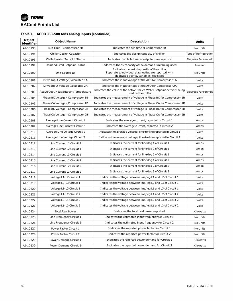
Table 7. ACRB 350–500 tons analog inputs (continued)
ObjectIdentifier
Object Name Description Units
AI-10195 Run Time - Compressor 2B Indicates the run time of Compressor 2B No Units
AI-10196 Chiller Design Capacity Indicates the design capacity of chilller Tons of Refrigeration
AI-10198 Chilled Water Setpoint Status Indicates the chilled water setpoint temperature Degrees Fahrenheit
AI-10199 Demand Limit Setpoint Status Indacates the% capacity of the demand limit being used Percent
AI-10200 Unit Source IDIndicates the last diagnostic of the chiller
Separately, individual diagnostics are reported withdedicated points, variables, registers
No Units
AI-10201 Drive Input Voltage Calculated 1A Indicates the input voltage at the AFD for Compressor 1A Volts
AI-10202 Drive Input Voltage Calculated 2A Indicates the input voltage at the AFD for Compressor 2A Volts
AI-10203 Active Cool/Heat Setpoint Temperature Indicates the value of the active Chilled Water Setpoint actively beingused by the chiller Degrees Fahrenheit
AI-10204 Phase BC Voltage - Compressor 1B Indicates the measurement of voltage in Phase BC for Compressor 1B Volts
AI-10205 Phase CA Voltage - Compressor 1B Indicates the measurement of voltage in Phase CA for Compressor 1B Volts
AI-10206 Phase BC Voltage - Compressor 2B Indicates the measurement of voltage in Phase BC for Compressor 2B Volts
AI-10207 Phase CA Voltage - Compressor 2B Indicates the measurement of voltage in Phase CA for Compressor 2B Volts
AI-10208 Average Line Current Circuit 1 Indicates the average current, reported in Circuit 1 Amps
AI-10209 Average Line Current Circuit 2 Indicates the average current, reported in Circuit 2 Amps
AI-10210 Average Line Voltage Circuit 1 Indicates the average voltage, line-to-line reported in Circuit 1 Volts
AI-10211 Average Line Voltage Circuit 2 Indicates the average voltage, line-to-line reported in Circuit 2 Volts
AI-10212 Line Current L1 Circuit 1 Indicates the current for line/leg 1 of Circuit 1 Amps
AI-10213 Line Current L2 Circuit 1 Indicates the current for line/leg 2 of Circuit 1 Amps
AI-10214 Line Current L3 Circuit 1 Indicates the current for line/leg 3 of Circuit 1 Amps
AI-10215 Line Current L1 Circuit 2 Indicates the current for line/leg 1 of Circuit 2 Amps
AI-10216 Line Current L2 Circuit 2 Indicates the current for line/leg 2 of Circuit 2 Amps
AI-10217 Line Current L3 Circuit 2 Indicates the current for line/leg 3 of Circuit 2 Amps
AI-10218 Voltage L1-L2 Circuit 1 Indicates the voltage between line/leg L1 and L2 of Circuit 1 Volts
AI-10219 Voltage L2-L3 Circuit 1 Indicates the voltage between line/leg L2 and L3 of Circuit 1 Volts
AI-10220 Voltage L1-L3 Circuit 1 Indicates the voltage between line/leg L1 and L3 of Circuit 1 Volts
AI-10221 Voltage L1-L2 Circuit 2 Indicates the voltage between line/leg L1 and L2 of Circuit 2 Volts
AI-10222 Voltage L2-L1 Circuit 2 Indicates the voltage between line/leg L2 and L3 of Circuit 2 Volts
AI-10223 Voltage L1-L3 Circuit 2 Indicates the voltage between line/leg L1 and L3 of Circuit 2 Volts
AI-10224 Total Real Power Indicates the total real power reported Kilowatts
AI-10225 Line Frequency Circuit 1 Indicates the estimated input frequency for Circuit 1 No Units
AI-10226 Line Frequency Circuit 2 Indicates the estimated input frequency for Circuit 2 No Units
AI-10227 Power Factor Circuit 1 Indicates the reported power factor for Circuit 1 No Units
AI-10228 Power Factor Circuit 2 Indicates the reported power factor for Circuit 2 No Units
AI-10229 Power Demand Circuit 1 Indicates the reported power demand for Circuit 1 Kilowatts
AI-10230 Power Demand Circuit 2 Indicates the reported power demand for Circuit 2 Kilowatts
BBAACCnneett PPooiinnttss LLiisstt

BAS-SVP045B-EN 25
Table 8. ACRB 350–500 tons analog values
AV-10100 Chilled Water Setpoint
The value is normally provided by the BAS to send the Chilled WaterSetpoint.
The value is subject to arbitration logic in the controller, in which case itmay or may not be used for control purposes
Degrees Fahrenheit
AV-10101 Demand Limit Setpoint
The value is normally provided by the BAS to send the Demand LimitSetpoint.
The value is subject to arbitration logic in the controller, in which case itmay or may not be used for control purposes
Percent
Table 9. ACRB 350–500 tons binary inputs
ObjectIdentifier
Object Name Description Object States
BI-10100 Run EnableIndicates that chiller is available to run or is currently
running0 = Run Not Enabled1 = Run Enabled
BI-10101 Local Setpoint Control Indicates the which setpoint is used for controlpurposes, Remote (BAS) or Local
0 = Remote control1 = Local control
BI-10102 Limit Mode Relay Status Indicates the status of the chiller limit relay 0 = Off1 = On
BI-10103 Chiller Running StateIndicates whether the chiller is on (currently doing
either cooling) or is considered off(not currently doingcooling)
0 = Off1 = On
BI-10104 Maximum Capacity Indicates the status of the maximum capacity relay 0 = Off1 = On
BI-10106 Manual Override Exists Indicated a manual override is present 0 = Off1 = On
BI-10107 Compressor 1A Status Indicates running state fo Compressor 1A 0 = Off1 = Running
BI-10108 Compressor 2A Status Indicates running state fo Compressor 2A 0 = Off1 = Running
BI-10109 Emergency Stop Indicates the status of the emergency stop function ofthe chiller
0 = Auto1 = Emergency Stop -Manual Reset Required
BI-10110 Evaporator Water Pump Request Indicates a request from the chiller to turn on theEvaporator Water Pump
0 = Off1 = On
BI-10111 Evaporator Water Flow Status Indicates the flow of water through evaporator 0 = No Flow1 = Flow
BI-10112 Compressor 1B Status Indicates running state of Compressor 1B 0 = Off1 = Running
BI-10113 Compressor 2B Status Indicates running state of Compressor 2B 0 = Off1 = Running
BI-10114 Free Cooling Active Indicated the free cooling mode is active 0 = Inactive1 = Active
BI-10116 Diagnostic Present Indicates whether diagnostic present 0 = Normal1 = In Alarm
BI-10117 Diagnostic Shutdown Present Indicates chiller is shut down due to diagnostics 0 = Normal1 = In Alarm
BI-10118 Diagnostic: Manual Reset Required Indicates when a diagnostic exists that requiresmanual reset
0 = Normal1 = In Alarm
BI-10119Diagnostic: Local Manual Reset
RequiredIndicates when a diagnostic exists that requires
manual reset [Local only]0 = Normal1 = In Alarm
BI-10120 Diagnostic Present: Information Indicates whether diagnostic present with InformationCategory
0 = Normal1 = In Alarm
BI-10121 Diagnostic Present: Advisory Indicates whether diagnostic present with WarningCategory
0 = Normal1 = In Alarm
BI-10122 Diagnostic Present: Critical Indicates whether diagnostic present with CriticalCategory
0 = Normal1 = In Alarm
BI-10123 Diagnostic Present: Service Required Indicates whether diagnostic present with ServiceRequired Category
0 = Normal1 = In Alarm
BI-10124 External Auto Stop Input Status Indicates the status of the externally-wired auto/stopinput
0 = Stop1 = Auto
BI-10125 Front Panel Auto Stop Indicates the auto/stop status of the Front Panel 0 = Stop1 = Auto
BI-10126 Noise Reduction Request Active Indicates wherther Noise Reduction active 0 = Off1 = On
BI-10127 Circuit 1 Lockout Front Panel Indicates the lockout state of Circuit 1 Comprosserfrom Front Panel
0 = Normal1 = Locked Out
BI-10128 Circuit 2 Lockout Front Panel Indicates the lockout state of Circuit 2 Comprosserfrom Front Panel
0 = Normal1 = Locked Out
BI-10129 Circuit 1 Lockout External Indicates the lockout state of Circuit 1 Comprosserfrom External
0 = Normal1 = Locked Out
BBAACCnneett PPooiinnttss LLiisstt

26 BAS-SVP045B-EN
Table 9. ACRB 350–500 tons binary inputs (continued)
ObjectIdentifier
Object Name Description Object States
BI-10130 Circuit 2 Lockout External Indicates the lockout state of Circuit 2 Comprosserfrom External
0 = Normal1 = Locked Out
BI-10131 Circuit 1 Lockout Active Indicates the lockout state of Circuit 1 Comprosser 0 = Normal1 = Locked Out
BI-10132 Circuit 2 Lockout Active Indicates the lockout state of Circuit 2 Comprosser 0 = Normal1 = Locked Out
Table 10. ACRB 350–500 tons binary values
ObjectIdentifier
Object Name Description Object States
BV-10100 Reset Diagnostic Normally used by the BMS to initiate a requestto reset any controller diagnostics
0 = Normal1 = Reset
BV-10101 Noise Reduction Request BASNormally used by the BMS to command the chiller toenter a mode of operation where the noise of the unit
is reduced
0 = Normal1 = Reduce Noise
BV-10102 Circuit 1 Lockout BASNormally used by the BMS to lockout the Circuit-1
Compressor0 = Normal
1 = Locked Out
BV-10103 Circuit 2 Lockout BASNormally used by the BMS to lockout the Circuit-2
Compressor0 = Normal
1 = Locked Out
BV-10107 Energy Consumption Reset Normally used by the BMS to reset the energyconsumption accumulated total
0 = Accumulating1 = Reset
BV-10108 Chiller Auto Stop Command BASNormally used by the BMS to command the chiller tostart running if operating conditions are satisfied, or to
stop the chiller from running.
0 = Stop1 = Auto
BV-10109 Free Cooling Auto Stop CommandBAS
Normally used the BMS to command the chiller toallow free cooling mode if conditions are satisfied, or
to stop the free cooling mode from operating.
0 = Stop1 = Auto
BV-10110 Free Cooling Compressor Lockout Normally used by the BMS to lockout the Compressorwhile in free cooling mode
0 = Normal1 = Locked Out
Table 11. ACRB 350–500 tons multi-state inputs
ObjectIdentifier
Object Name Description Object States
MI-10100 Running Mode Indicates the running state of the chiller
1 = Chiller Off2 = Chiller In Start Mode3= Chiller In Run Mode
4= Chiller In Pre-Shutdown Mode5 = Chiller In Service Mode
MI-10101 Operating Mode Indicates the operating mode of the chiller
1 = Cool2 = Heat
3= Ice Making4= Free Cooling
MI-10102 Refrigerant Type Indicates the chiller refrigerant type
1 = R-112 = R-123= R-224= R-1235 = R-134a6 = R-407C7 = R-410A8 = R-1139 = R-11410 = R-50011 = R-50212 = R-404A13 = R-513A
14 = R-1233zd(E)15 = R-514A
16 = R-1234ze(E)
MI-10103 Cooling Type Indicates the cooling Type of chiller 1 =Water Cooled2 = Air Cooled
BBAACCnneett PPooiinnttss LLiisstt

BAS-SVP045B-EN 27
Table 11. ACRB 350–500 tons multi-state inputs (continued)
MI-10104 Manufacture Location Indicates the location that the chiller was manufactured
1 = Field Applied2 = La Crosse3= Pueblo4= Charmes5 = Rushville6 = Macon7 =Waco
8 = Lexington9 = Forsyth
10 = Clarksville11 = Ft. Smith12 = Penang13 = Colchester14 = Curitiba15 = Taicang16 = Taiwan17 = Epinal18 = Golbey
MI-10105 Model Information [GEN2] Indicates the model information of chiller
1 = CVHF2 = CVGF3= CVHS4= RTAE5 = RTAF6 = RTHA7 = RTHB8 = RTHC9 = RTHD10 = RTWE11 = CTVD12 = CVR13 = CVHH14 = CDHH15 = VMAX16 = GVAF17 = RTWF18 = RTHF19 = RTAC20 = CVHM21 = RTAG22 = CGAF23 = RTXG24 = GVWF25 = HDWA26 = CMAC27 = IPAK28 = CXAF29 = ACSA30 = RTSF31 = HSWA32 = ACRA33 = RTEG34 = ACXA35 = CMAF
36 = ACRB Large37 = ACRB Small
MI-10106 Chiller Setpoint Source Indicates the selected setpoint source for controlpurpose
1 = BAS2 = External3 = Front Panel
Table 12. ACRB 350–500 tons multi-state values
Object Identifier Object Name Description Object States
MV-10100 BAS Chiller Mode Command Normally used by the BMS to command the chiller Mode
1 = Cool2 = Heat
3= Ice Making4= Free Cooling
BBAACCnneett PPooiinnttss LLiisstt

28 BAS-SVP045B-EN
Recycled PointsThe Symbio™ 800 controller ships from the factory pre-configured for the specific unitapplication. The points of the communicated interface (BACnet, Modbus, or LonTalk) vary basedon the unit configuration. Only those points pertinent to that configuration are included in theinterface.
Example: When the unit is configured for only two compressors, any points associated withcompressors three and four are not be displayed on the Touch Screen interface or browser-based Web user interface. When configuration changes are made in the field, the points in thecommunication interface change accordingly to align with those features or user-added points.
Figure 13. Points
Any of the factory-provided points can be removed from the communication interface through afeature known as recycling. When the user selects and deletes a factory point, that point ismoved to Recycled Points and is removed from the interface. This feature offers technicians theability to strategically provide only those interface points desired for a specific project orinstallation.
To remove a point from the interface:
1. On the left-hand navigation, select PPooiinnttss.
2. Each of the points are grouped by their native type (analog, binary or multi-state), and input,output, or value. Select the appropriate group at the top of the page.
3. Select one or more points from the list and select AAccttiioonnss...... || DDeelleettee.
BBAACCnneett PPooiinnttss LLiisstt

BAS-SVP045B-EN 29
Figure 14. Delete points
NNoottee:: User-created points cannot be recycled. Instead, when the user selects and deletes user-created points, those points are permanently removed from the controller. Should the userdecide later that one or more of the deleted user points are needed, they will need to berecreated.
To restore recycled points:
1. Navigate to the RReeccyycclleedd PPooiinnttss tab on the Points page.
2. Select one or more points to be restored, then click RReessttoorree.
3. Once the restore process is complete, the restored points are moved back to the appropriatetab depending on point type. The recycled points also appear in the communicated interfaceonce they are restored.
BBAACCnneett PPooiinnttss LLiisstt

30 BAS-SVP045B-EN
Figure 15. Recycled points tab
BBAACCnneett PPooiinnttss LLiisstt
BAS-SVP045B-EN 31
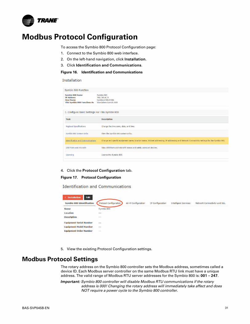
Modbus Protocol ConfigurationTo access the Symbio 800 Protocol Configuration page:
1. Connect to the Symbio 800 web interface.
2. On the left-hand navigation, click IInnssttaallllaattiioonn.
3. Click IIddeennttiiffiiccaattiioonn aanndd CCoommmmuunniiccaattiioonnss.
Figure 16. Identification and Communications
4. Click the PPrroottooccooll CCoonnffiigguurraattiioonn tab.
Figure 17. Protocol Configuration
5. View the existing Protocol Configuration settings.
Modbus Protocol SettingsThe rotary address on the Symbio 800 controller sets the Modbus address, sometimes called adevice ID. Each Modbus server controller on the same Modbus RTU link must have a uniqueaddress. The valid range of Modbus RTU server addresses for the Symbio 800 is: 000011 –– 224477.
IImmppoorrttaanntt:: Symbio 800 controller will disable Modbus RTU communications if the rotaryaddress is 000! Changing the rotary address will immediately take affect and doesNOT require a power cycle to the Symbio 800 controller.
32 BAS-SVP045B-EN
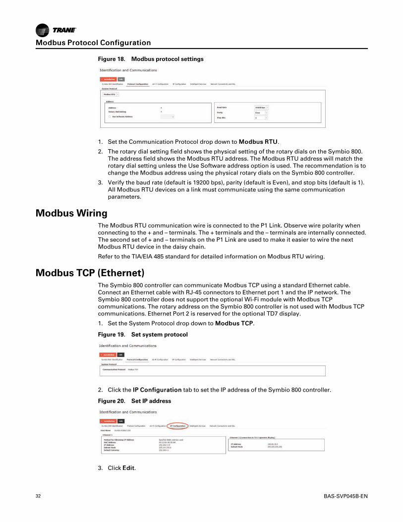
Figure 18. Modbus protocol settings
1. Set the Communication Protocol drop down to MMooddbbuuss RRTTUU.
2. The rotary dial setting field shows the physical setting of the rotary dials on the Symbio 800.The address field shows the Modbus RTU address. The Modbus RTU address will match therotary dial setting unless the Use Software address option is used. The recommendation is tochange the Modbus address using the physical rotary dials on the Symbio 800 controller.
3. Verify the baud rate (default is 19200 bps), parity (default is Even), and stop bits (default is 1).All Modbus RTU devices on a link must communicate using the same communicationparameters.
Modbus WiringThe Modbus RTU communication wire is connected to the P1 Link. Observe wire polarity whenconnecting to the + and – terminals. The + terminals and the – terminals are internally connected.The second set of + and – terminals on the P1 Link are used to make it easier to wire the nextModbus RTU device in the daisy chain.
Refer to the TIA/EIA 485 standard for detailed information on Modbus RTU wiring.
Modbus TCP (Ethernet)The Symbio 800 controller can communicate Modbus TCP using a standard Ethernet cable.Connect an Ethernet cable with RJ-45 connectors to Ethernet port 1 and the IP network. TheSymbio 800 controller does not support the optional Wi-Fi module with Modbus TCPcommunications. The rotary address on the Symbio 800 controller is not used with Modbus TCPcommunications. Ethernet Port 2 is reserved for the optional TD7 display.
1. Set the System Protocol drop down to MMooddbbuuss TTCCPP.
Figure 19. Set system protocol
2. Click the IIPP CCoonnffiigguurraattiioonn tab to set the IP address of the Symbio 800 controller.
Figure 20. Set IP address
3. Click EEddiitt.
MMooddbbuuss PPrroottooccooll CCoonnffiigguurraattiioonn

BAS-SVP045B-EN 33
Figure 21. Edit IP configuration
4. Setup the Ethernet 1 port to either ‘Obtain an IP addresss Automatically using DHCP’ or use astatic IP address by manually entering the IP address, subnet mask, and default gateway. TheIP address information is typically provided by the local IT administrator.
5. Set the Preferred IP Interface to EEtthheerrnneett 11.
6. Set up the DNS section if using a Domain Name System server to identify the Symbio 800controller by host name.
MMooddbbuuss PPrroottooccooll CCoonnffiigguurraattiioonn
34 BAS-SVP045B-EN
Modbus Points ListObject Naming Conventions
The communicated points for the Symbio™ controllers are generally named according to theirfunction. While many of the points are read-only, others include both read and write capability.The established naming convention helps to identify the capabilities of each point. For mostpoints, the suffix identifies the capability according to the following definition.
While there are some exceptions, the majority of the points have been defined according to theseguidelines.
Suffix Description
Status Points with the Status suffix are defined as read-only. The status point reports thevalue being used by the controller.
Local Points with the Local suffix are defined as read-only. The local point reports valuesassociated with controller sensors, both wired and wireless. The local value mayor may not be actively used by the controller, depending on the presence orabsence of a communicated value (BAS). When both a local and communicatedvalue exist, the communicated value is used.
Active Points with the Active suffix are defined as read-only. Points designated as activeare normally the result of the arbitration between a communicated value (BAS)and at least one value local to the equipment, such as a sensor or defaultsetpoint. The active point reports the value being used by the controller.
Setpoint Points with the Setpoint suffix are defined as either read-only or read/write. ForBACnet, the binary input, analog input and multi-state input points are all read-only. These setpoints report the value currently in use by the controller.The analog value, binary value and multi-state value points are all read/write.These points are provided for use by the building automation system (BAS).When used, these points are written internally to arbitration logic. This definesthe interaction with hardwired points, editable software configuration points andthe relinquish default value/state. Refer to the Appendix for additionalinformation.
Input Points with the Input suffix are defined as read-only. These points normally reflectthe status of a sensor input, either hardwired or communicating wirelessly (Air-Fi). However, the input point reflects the arbitrated result of the controller sensorinput and a communicated value, if present. When both a controller sensor andcommunicated value exist, the controller will use and report the communicatedvalue.
Arbitrator Points with the “Arbitrator” suffix are to be used as read-only. The arbitratorprioritizes inputs from communicating points, hardwired points and storeddefaults points. The priority array of the arbitration point displays each of thevalues provided, including the active status, indicating which of the input sourcesis being used. Refer to the Appendix for additional information.
BAS Points with the BAS suffix are defined as read/write. These points are provided foruse by the building automation system (BAS). When used, these points arewritten to arbitration logic. This defines the interaction with hardwired points,editable software configuration points and the relinquished default value/state.Refer to the Appendix for additional information.
Command Points with the Command suffix are defined as read/write. These points arewritten to change the default behavior of the controller. Once written, these pointvalues may be persisted.
Request Points with the Request suffix are defined as read/write. These points are writtento change the operating behavior of the controller.
Object Data Points and Diagnostic Data PointsACRB 150–300 Tons Data PointsThe following tables are sorted as follows:
• Tables are listed by input/output type and sorted by object identifier. These tables provide theuser with the units type for each object type.

BAS-SVP045B-EN 35
• Tables are sorted by object name and provide a complete list of object names, types, values/ranges, and descriptions.
NNoottee:: Not all points are available to the user. The available data points are defined duringself-configuration and are dependent on the type of equipment.
Table 13. ACRB 150–300 tons analog inputs
ModbusRegister
DataType Object Name Description Units
30011 Float Active Chilled Water Setpoint Indicates the value of the active Chilled WaterSetpoint actively being used by the chiller Degrees Fahrenheit
30013 Float Evaporator Entering Water Temperature Indicates the current temperature of thewater entering the evaporator Degrees Fahrenheit
30015 Float Evaporator Leaving Water Temperature Indicates the current temperature of thewater leaving the evaporator Degrees Fahrenheit
30017 Float Calculated Chiller Capacity Indicates the capacity the chiller is currentlyusing Tons of Refrigeration
30019 Float Active Demand Limit Setpoint Indicates the demand limit setpoint valueactively being used by the chiller Percent
30021 Float Unit Power Consumption Indicates the measurement of the powerbeing consumed by the Chiller Kilowatts
30025 Float Outdoor Air Temperature Indicates the current temperature of theoutdoor air
Degrees Fahrenheit
30027 Float Evaporator Refrigerant Pressure Circuit1
Indicates the current pressure of therefrigerant in the evaporator on circuit 1
Pound Force perSquare Inch
30029 Float Condenser Refrigerant Pressure Circuit1
Indicates the current pressure of therefrigerant in the condenser on circuit 1
Pound Force perSquare Inch
30031 Float Differential Refrigerant Pressure Circuit1
Indicates the pressure difference between thesuction and discharge lines on circuit 1
Pound Force perSquare Inch
30033 FloatEvaporator Saturated Refrigerant
Temperature Circuit 1
Indicates the saturated_x000D_refrigerant temperature of the evaporator oncircuit 1
Degrees Fahrenheit
30035 FloatCondenser Saturated Refrigerant
Temperature Circuit 1
Indicates the saturated_x000D_refrigerant temperature of the condenser oncircuit 1
Degrees Fahrenheit
30037 Float Evaporator Refrigerant Pressure Circuit2
Indicates the current pressure of therefrigerant in the evaporator on circuit 2
Pound Force perSquare Inch
30039 Float Condenser Refrigerant Pressure Circuit2
Indicates the current pressure of therefrigerant in the condenser on circuit 2
Pound Force perSquare Inch
30041 Float Differential Refrigerant Pressure Circuit2
Indicates the pressure difference between thesuction and discharge lines on circuit 2
Pound Force perSquare Inch
30043 FloatEvaporator Saturated Refrigerant
Temperature Circuit 2
Indicates the saturated_x000D_refrigerant temperature of the evaporator oncircuit 2
Degrees Fahrenheit
30045 FloatCondenser Saturated Refrigerant
Temperature Circuit 2
Indicates the saturated_x000D_refrigerant temperature of the condenser oncircuit 2
Degrees Fahrenheit
30047 FloatRefrigerant Discharge Temperature -
Compressor 1A
Indicates the current temperature of therefrigerant being discharged fromCompressor 1A
Degrees Fahrenheit
30049 Float Oil Pressure - Compressor 1A Indicates the pressure of the oil on the highpressure side of Compressor 1A
Pound Force perSquare Inch
30051 FloatRefrigerant Discharge Temperature -
Compressor 2A
Indicates the current temperature of therefrigerant being discharged fromCompressor 2A
Degrees Fahrenheit
30053 Float Oil Pressure - Compressor 2A Indicates the pressure of the oil on the highpressure side of Compressor 2A
Pound Force perSquare Inch
30055 Float Air Flow Percentage Circuit 1 Indicates the approximate air flow percentageof Circuit 1 Percent
30057 Float Air Flow Percentage Circuit 2 Indicates the approximate air flow percentageof Circuit 2 Percent
30059 Float Starts - Compressor 1A Indicates the number of starts of Compressor1A No Units
30061 Float Run Time - Compressor 1A Indicates the run time of Compressor 1A, inhours Hours
30063 Float Compressor 1A Speed Status Indicates the% of the available speed beingused by Compressor 1A Percent
30065 Float Motor Winding Temperature 1 Circuit 1 Indicates the first temperaure sensor of thewindings on motor 1A Degrees Fahrenheit
30067 Float Motor Winding Temperature 2 Circuit 1 Indicates the second temperaure sensor ofthe windings on motor 1A Degrees Fahrenheit
30069 Float Drive Motor Current U RLA Compressor1A
Indicates the measurement of Line 1 currentat AFD for Compressor 1A in terms of % RLA Percent
MMooddbbuuss PPooiinnttss LLiisstt

36 BAS-SVP045B-EN
Table 13. ACRB 150–300 tons analog inputs (continued)
ModbusRegister
DataType Object Name Description Units
30071 Float Drive Motor Current V RLA Compressor1A
Indicates the measurement of Line 2 currentat AFD for Compressor 1A in terms of % RLA Percent
30073 Float Drive Motor Current W RLA Compressor1A
Indicates the measurement of Line 3 currentat AFD for Compressor 1A in terms of % RLA Percent
30075 FloatDrive Motor Average Current RLA
Compressor 1AIndicates the average current at AFD forCompressor 1A in terms of % RLA Percent
30077 Float Drive Motor Current U Compressor 1A Indicates the measurement of Line 1 currentat AFD for Compressor 1A in terms of Amps Amps
30079 Float Drive Motor Current V Compressor 1A Indicates the measurement of Line 2 currentat AFD for Compressor 1A in terms of Amps Amps
30081 Float Drive Motor Current W Compressor 1A Indicates the measurement of Line 3 currentat AFD for Compressor 1A in terms of Amps Amps
30083 Float Drive Motor Voltage UV Circuit 1Indicates the measurement of voltagebetween Line 1 to 2 at the AFD forCompressor 1A
Volts
30085 Float Drive Motor Voltage VW Circuit 1Indicates the measurement of voltagebetween Line 2 to 3 at the AFD forCompressor 1A
Volts
30087 Float Drive Motor Voltage WU Circuit 1Indicates the measurement of voltagebetween Line 3 to 1 at the AFD forCompressor 1A
Volts
30089 Float Drive Motor Average Voltage Circuit 1 Indicates the average voltage line to line atAFD for Compressor 1A Volts
30091 Float Drive DC Bus Voltage Circuit 1 Indicates the voltage of the DC Bus from theAFD for Compressor 1A Volts
30093 Float Drive Output Power Circuit 1 Indicates the power output from the AFD forCompressor 1A Kilowatts
30095 Float Drive Input Power Circuit 1 Indicates the power input for the AFD forCompressor 1A Kilowatts
30097 Float Drive Line Average Voltage Circuit 1 Indcates the average input voltage at the AFDfor Compressor 1A Volts
30099 Float Drive Average Line Current Circuit 1 Indcates the average input current at the AFDfor Compressor 1A Amps
30101 Float Drive Line Frequency Circuit 1 Indicates the estimated input frequency at theAFD for Compressor 1A
feet per secondper second
30103 Float AFD Frequency Circuit 1 Indicates the frequency at the stator for AFDfor Compressor 1A
feet per secondper second
30105 Float AFD Transistor Temperature Circuit 1 Indicates the temperature of the transistor forthe AFD for Compressor 1A Degrees Fahrenheit
30107 Float Drive Inverter Base Temperature Circuit1
Indicates the temperature of the inverter basefor the AFD for Compressor 1A Degrees Fahrenheit
30109 Float Drive Rectifier Base Temperature Circuit1
Indicates the temperature of the rectifier basefor the AFD for Compressor 1A Degrees Fahrenheit
30111 Float Starts - Compressor 2A Indicates the number of starts of Compressor2A No Units
30113 Float Run Time - Compressor 2A Indicates the run time of_x000D_Compressor 2A, in hours No Units
30115 Float Compressor 2A Speed Status Indicates the% of the available speed beingused by Compressor 2A Percent
30117 Float Motor Winding Temperature 1 Circuit 2 Indicates the first temperaure sensor of thewindings on motor 2A Degrees Fahrenheit
30119 Float Motor Winding Temperature 2 Circuit 2 Indicates the second temperaure sensor ofthe windings on motor 2A Degrees Fahrenheit
30121 Float Drive Motor Current U RLA Compressor2A
Indicates the measurement of Line 1 currentat AFD for Compressor 2A in terms of % RLA Percent
30123 Float Drive Motor Current V RLA Compressor2A
Indicates the measurement of Line 2 currentat AFD for Compressor 2A in terms of % RLA Percent
30125 Float Drive Motor Current W RLA Compressor2A
Indicates the measurement of Line 3 currentat AFD for Compressor 2A in terms of % RLA Percent
30127 FloatDrive Motor Average Current RLA
Compressor 2AIndicates the average current at AFD forCompressor 2A in terms of % RLA Percent
30129 Float Drive Motor Current U Compressor 2A Indicates the measurement of Line 1 currentat AFD for Compressor 2A in terms of Amps Amps
30131 Float Drive Motor Current V Compressor 2A Indicates the measurement of V line currentat AFD for Compressor 2A in terms of Amps Amps
30133 Float Drive Motor Current W Compressor 2A Indicates the measurement of W line currentat AFD for Compressor 2A in terms of Amps Amps
30135 Float Drive Motor Voltage UV Circuit 2 Indicates the measurement of voltagebetween Line 1 to 2 at AFD for Compressor 2A Volts
MMooddbbuuss PPooiinnttss LLiisstt

BAS-SVP045B-EN 37
Table 13. ACRB 150–300 tons analog inputs (continued)
ModbusRegister
DataType Object Name Description Units
30137 Float Drive Motor Voltage VW Circuit 2 Indicates the measurement of voltagebetween Line 2 to 3 at AFD for Compressor 2A Volts
30139 Float Drive Motor Voltage WU Circuit 2 Indicates the measurement of voltagebetween Line 3 to 1 at AFD for Compressor 2A Volts
30141 Float Drive Motor Average Voltage Circuit 2 Indicates the average voltage line to line atAFD for Compressor 2A Volts
30143 Float Drive DC Bus Voltage Circuit 2 Indicates the voltage of the DC Bus from theAFD for Compressor 2A Volts
30145 Float Drive Output Power Circuit 2 Indicates the power output from the AFD forCompressor 2A Kilowatts
30147 Float Drive Input Power Circuit 2 Indicates the power input for the AFD forCompressor 2A Kilowatts
30149 Float Drive Line Average Voltage Circuit 2 Indcates the average input voltage at the AFDfor Compressor 2A Volts
30151 Float Drive Average Line Current Circuit 2 Indcates the average input current at the AFDfor Compressor 2A Amps
30153 Float Drive Line Frequency Circuit 2 Indicates the estimated input frequency at theAFD for Compressor 2A
feet per secondper second
30155 Float AFD Frequency Circuit 2 Indicates the frequency at the stator for AFDfor Compressor 2A
feet per secondper second
30157 Float AFD Transistor Temperature Circuit 2 Indicates the temperature of the transidtor forthe AFD for Compressor 2A Degrees Fahrenheit
30159 Float Drive Inverter Base Temperature Circuit2
Indicates the temperature of the inverter basefor the AFD for Compressor 2A Degrees Fahrenheit
30161 Float Drive Rectifier Base Temperature Circuit2
Indicates the temperature of the rectifier basefor the AFD for Compressor 2A Degrees Fahrenheit
30163 Float Number Of CircuitsIndicates the number of refrigeration circuitsin thechiller
No Units
30165 Float Number Of Compressors Circuit 1 Indicates the number of compressors oncircuit 1 of the chiller No Units
30167 Float Number Of Compressors Circuit 2Indicates the number of compressors oncircuit 2 ofthe chiller
No Units
30169 Float Free Cooling Capacity Indicates the% capacity of the free coolingbeing used Percent
30171 FloatFree Cooling Entering Water
TemperatureIndiactes the entering water temperature ofthe free cooling circuit Degrees Fahrenheit
30173 Float Energy Consumption Lifetime Indicates the total energy consumption of thechiller (for the lifetime of the chiller) Kilowatts hour
30175 Float Energy Consumption Indicates the total energy consumption of thechiller (since last accumulation reset) Kilowatts hour
30177 Float Unit Source ID
Indicates the last diagnostic of the chillerSeparately, individual diagnostics arereported withdedicated points, variables, registers
No Units
30179 Float Chiller Design Capacity Indicates the design capacity of chilller Tons of Refrigeration
30181 Float Active Cool/Heat Setpoint Temperature Indicates the value of the active Chilled WaterSetpoint actively being used by the chiller Degrees Fahrenheit
30183 Float Actual Running Capacity Indicates the measurement of the powerbeing consumed by the Chiller Percent
Table 14. ACRB 150–300 tons analog values
ModbusRegister Data Type Object Name Description Units
40010 Float Chilled Water Setpoint
The value is normally provided by the BAS to send theChilled Water Setpoint.The value is subject to arbitration logic in thecontroller, in which case it may or may not be used forcontrol purposes
Degrees Fahrenheit
40012 Float Demand Limit Setpoint
The value is normally provided by the BAS to send theDemand Limit Setpoint.The value is subject to arbitration logic in thecontroller, in which case it may or may not be used forcontrol purposes
Percent
MMooddbbuuss PPooiinnttss LLiisstt

38 BAS-SVP045B-EN
Table 15. ACRB 150–300 tons binary inputs
ModbusRegister Data Type Object Name Description Object States
33010 Signed Integer 16-bit Run EnableIndicates that chiller is available to run or iscurrently running
0 = Run Not Enabled1 = Run Enabled
33011 Signed Integer 16-bit Local Setpoint Control Indicates the which setpoint is used for controlpurposes, Remote (BAS) or Local0 = Remote control1 = Local control
33012 Signed Integer 16-bit Limit Mode RelayStatus
Indicates the status of the chiller limit relay 0 = Off1 = On
33013 Signed Integer 16-bit Chiller Running StateIndicates whether the chiller is on (currently doingeither cooling) or is considered off(not currentlydoing cooling)
0 = Off1 = On
33014 Signed Integer 16-bit Maximum CapacityRelay
Indicates the status of the maximum capacityrelay
0 = Off1 = On
33015 Signed Integer 16-bit Evaporator WaterPump Command
Indicates a request from the chiller to turn on theEvaporator Water Pump
0 = Off1 = On
33016 Signed Integer 16-bit Evaporator Water FlowStatus
Indicates the flow of water through evaporator 0 = No Flow1 = Flow
33017 Signed Integer 16-bit Manual Override Exists Indicated a manual override is present 0 = Off1 = On
33018 Signed Integer 16-bit Emergency Stop Indicates the status of the emergency stopfunction of the chiller
0 = Auto1 = Emergency Stop -Manual Reset Required
33019 Signed Integer 16-bit Diagnostic Present Indicates whether diagnostic present 0 = Normal1 = In Alarm
33020 Signed Integer 16-bit Diagnostic ShutdownPresent
Indicates chiller is shut down due to diagnostics 0 = Normal1 = In Alarm
33021 Signed Integer 16-bit Diagnostic: ManualReset Required
Indicates when a diagnostic exists that requiresmanual reset
0 = Normal1 = In Alarm
33022 Signed Integer 16-bit Diagnostic: LocalManual Reset Required
Indicates when a diagnostic exists that requiresmanual reset [Local only]
0 = Normal1 = In Alarm
33023 Signed Integer 16-bit Diagnostic Present:Information
Indicates whether diagnostic present withInformation Category
0 = Normal1 = In Alarm
33024 Signed Integer 16-bit Diagnostic Present:Warning
Indicates whether diagnostic present with WarningCategory
0 = Normal1 = In Alarm
33025 Signed Integer 16-bit Diagnostic Present:Critical
Indicates whether diagnostic present with CriticalCategory
0 = Normal1 = In Alarm
33026 Signed Integer 16-bit Diagnostic Present:Service Required
Indicates whether diagnostic present with ServiceRequired Category
0 = Normal1 = In Alarm
33027 Signed Integer 16-bit Running StatusCprsr1A Indicates running state fo Compressor 1A 0 = Off
1 = Running
33028 Signed Integer 16-bit Running StatusCprsr2A Indicates running state fo Compressor 2A 0 = Off
1 = Running
33029 Signed Integer 16-bit Free Cooling Active Indicated the free cooling mode is active 0 = Inactive1 = Active
33030 Signed Integer 16-bit External Auto Stop Indicates the status of the externally-wired auto/stop input
0 = Stop1 = Auto
33031 Signed Integer 16-bit Front Panel Auto/Stop Indicates the auto/stop status of the Front Panel 0 = Stop1 = Auto
33032 Signed Integer 16-bit Noise ReductionRequest Active Indicates whether Noise Reduction active 0 = Off
1 = On
Table 16. ACRB 150–300 tons binary values
ModbusRegister Data Type Object Name Description Object
States
43010Signed
Integer 16-bit Reset DiagnosticNormally used by the BMS to initiate a request
to reset any controller diagnostics0 = Normal1 = Reset
43011Signed
Integer 16-bitNoise ReductionRequest BAS
Normally used by the BMS to command the chiller to enter a mode ofoperation where the noise of the unit is reduced
0 = Normal1 = ReduceNoise
43012Signed
Integer 16-bitChiller Auto StopCommand BAS
Normally used by the BMS to command the chiller to start running ifoperating conditions are satisfied, or to stop the chiller from running.
0 = Stop1 = Auto
43013Signed
Integer 16-bitFree Cooling Auto Stop
Command BAS
Normally used the BMS to command the chiller to allow free coolingmode if conditions are satisfied, or to stop the free cooling mode from
operating.0 = Stop1 = Auto
43014Signed
Integer 16-bitFree Cooling
Compressor LockoutNormally used by the BMS to lockout the Compressor while in free
cooling mode
0 = Normal1 = Locked
Out
MMooddbbuuss PPooiinnttss LLiisstt

BAS-SVP045B-EN 39
Table 16. ACRB 150–300 tons binary values (continued)
ModbusRegister Data Type Object Name Description Object
States
43015Signed
Integer 16-bit Circuit 1 Lockout BAS Normally used by the BMS to lockout the Circuit-1 Compressor
0 = Normal1 = Locked
Out
43016Signed
Integer 16-bit Circuit 2 Lockout BAS Normally used by the BMS to lockout the Circuit-2 Compressor
0 = Normal1 = Locked
Out
43017Signed
Integer 16-bitEnergy Consumption
ResetNormally used by the BMS to reset the energy consumption
accumulated total
0 =Accumulat-
ing1 = Reset
Table 17. ACRB 150–300 tons multi-state inputs
ModbusRegister Data Type Object Name Description Object States
32010 Unsigned Integer 16-bit Running Mode Indicates the running state of the chiller
1 = Chiller Off2 = Chiller In Start Mode3= Chiller In Run Mode
4= Chiller In Pre-ShutdownMode
5 = Chiller In Service Mode
32011 Unsigned Integer 16-bit Operating Mode Indicates the operating mode of the chiller
1 = Cool2 = Heat
3= Ice Making4= Free Cooling
32012 Unsigned Integer 16-bit Chiller SetpointSource
Indicates the selected setpoint source forcontrol purpose
1 = BAS2 = External3 = Front Panel
32013 Unsigned Integer 16-bit Refrigerant Type Indicates the chiller refrigerant type
1 = R-112 = R-123= R-224= R-1235 = R-134a6 = R-407C7 = R-410A8 = R-1139 = R-11410 = R-50011 = R-50212 = R-404A13 = R-513A
14 = R-1233zd(E)15 = R-514A
16 = R-1234ze(E)
32014 Unsigned Integer 16-bit Cooling Type Indicates the cooling Type of chiller 1 = Water Cooled2 = Air Cooled
MMooddbbuuss PPooiinnttss LLiisstt
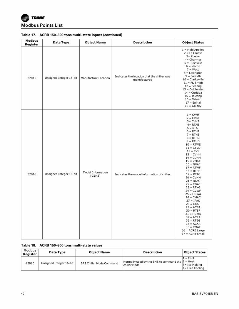
40 BAS-SVP045B-EN
Table 17. ACRB 150–300 tons multi-state inputs (continued)
ModbusRegister Data Type Object Name Description Object States
32015 Unsigned Integer 16-bit Manufacture Location Indicates the location that the chiller wasmanufactured
1 = Field Applied2 = La Crosse3= Pueblo4= Charmes5 = Rushville6 = Macon7 =Waco
8 = Lexington9 = Forsyth
10 = Clarksville11 = Ft. Smith12 = Penang13 = Colchester14 = Curitiba15 = Taicang16 = Taiwan17 = Epinal18 = Golbey
32016 Unsigned Integer 16-bit Model Information[GEN2] Indicates the model information of chiller
1 = CVHF2 = CVGF3= CVHS4= RTAE5 = RTAF6 = RTHA7 = RTHB8 = RTHC9 = RTHD10 = RTWE11 = CTVD12 = CVR13 = CVHH14 = CDHH15 = VMAX16 = GVAF17 = RTWF18 = RTHF19 = RTAC20 = CVHM21 = RTAG22 = CGAF23 = RTXG24 = GVWF25 = HDWA26 = CMAC27 = IPAK28 = CXAF29 = ACSA30 = RTSF31 = HSWA32 = ACRA33 = RTEG34 = ACXA35 = CMAF
36 = ACRB Large37 = ACRB Small
Table 18. ACRB 150–300 tons multi-state valuesModbusRegister Data Type Object Name Description Object States
42010 Unsigned Integer 16-bit BAS Chiller Mode Command Normally used by the BMS to command thechiller Mode
1 = Cool2 = Heat3= Ice Making4= Free Cooling
MMooddbbuuss PPooiinnttss LLiisstt
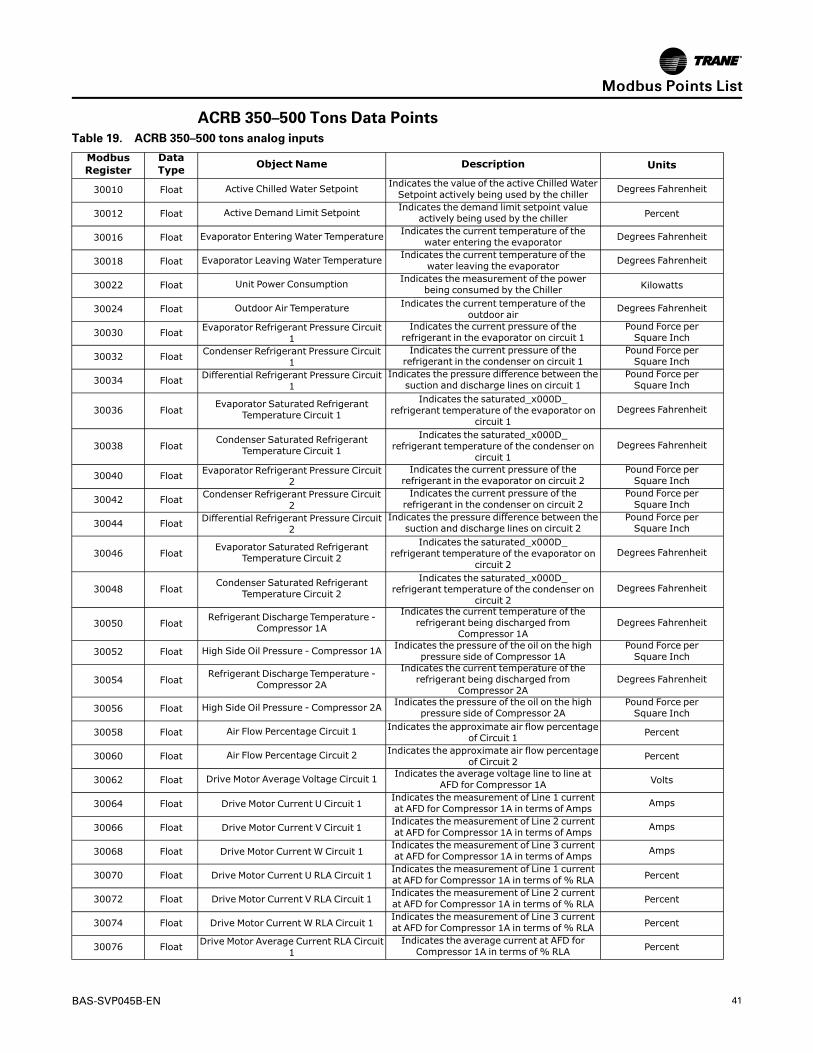
BAS-SVP045B-EN 41
ACRB 350–500 Tons Data PointsTable 19. ACRB 350–500 tons analog inputs
ModbusRegister
DataType Object Name Description Units
30010 Float Active Chilled Water Setpoint Indicates the value of the active Chilled WaterSetpoint actively being used by the chiller Degrees Fahrenheit
30012 Float Active Demand Limit Setpoint Indicates the demand limit setpoint valueactively being used by the chiller Percent
30016 Float Evaporator Entering Water Temperature Indicates the current temperature of thewater entering the evaporator Degrees Fahrenheit
30018 Float Evaporator Leaving Water Temperature Indicates the current temperature of thewater leaving the evaporator Degrees Fahrenheit
30022 Float Unit Power Consumption Indicates the measurement of the powerbeing consumed by the Chiller Kilowatts
30024 Float Outdoor Air Temperature Indicates the current temperature of theoutdoor air
Degrees Fahrenheit
30030 Float Evaporator Refrigerant Pressure Circuit1
Indicates the current pressure of therefrigerant in the evaporator on circuit 1
Pound Force perSquare Inch
30032 Float Condenser Refrigerant Pressure Circuit1
Indicates the current pressure of therefrigerant in the condenser on circuit 1
Pound Force perSquare Inch
30034 Float Differential Refrigerant Pressure Circuit1
Indicates the pressure difference between thesuction and discharge lines on circuit 1
Pound Force perSquare Inch
30036 FloatEvaporator Saturated Refrigerant
Temperature Circuit 1
Indicates the saturated_x000D_refrigerant temperature of the evaporator on
circuit 1Degrees Fahrenheit
30038 FloatCondenser Saturated Refrigerant
Temperature Circuit 1
Indicates the saturated_x000D_refrigerant temperature of the condenser on
circuit 1Degrees Fahrenheit
30040 Float Evaporator Refrigerant Pressure Circuit2
Indicates the current pressure of therefrigerant in the evaporator on circuit 2
Pound Force perSquare Inch
30042 Float Condenser Refrigerant Pressure Circuit2
Indicates the current pressure of therefrigerant in the condenser on circuit 2
Pound Force perSquare Inch
30044 Float Differential Refrigerant Pressure Circuit2
Indicates the pressure difference between thesuction and discharge lines on circuit 2
Pound Force perSquare Inch
30046 FloatEvaporator Saturated Refrigerant
Temperature Circuit 2
Indicates the saturated_x000D_refrigerant temperature of the evaporator on
circuit 2Degrees Fahrenheit
30048 FloatCondenser Saturated Refrigerant
Temperature Circuit 2
Indicates the saturated_x000D_refrigerant temperature of the condenser on
circuit 2Degrees Fahrenheit
30050 FloatRefrigerant Discharge Temperature -
Compressor 1A
Indicates the current temperature of therefrigerant being discharged from
Compressor 1ADegrees Fahrenheit
30052 Float High Side Oil Pressure - Compressor 1A Indicates the pressure of the oil on the highpressure side of Compressor 1A
Pound Force perSquare Inch
30054 FloatRefrigerant Discharge Temperature -
Compressor 2A
Indicates the current temperature of therefrigerant being discharged from
Compressor 2ADegrees Fahrenheit
30056 Float High Side Oil Pressure - Compressor 2A Indicates the pressure of the oil on the highpressure side of Compressor 2A
Pound Force perSquare Inch
30058 Float Air Flow Percentage Circuit 1 Indicates the approximate air flow percentageof Circuit 1 Percent
30060 Float Air Flow Percentage Circuit 2 Indicates the approximate air flow percentageof Circuit 2 Percent
30062 Float Drive Motor Average Voltage Circuit 1 Indicates the average voltage line to line atAFD for Compressor 1A Volts
30064 Float Drive Motor Current U Circuit 1Indicates the measurement of Line 1 currentat AFD for Compressor 1A in terms of Amps Amps
30066 Float Drive Motor Current V Circuit 1Indicates the measurement of Line 2 currentat AFD for Compressor 1A in terms of Amps Amps
30068 Float Drive Motor Current W Circuit 1Indicates the measurement of Line 3 currentat AFD for Compressor 1A in terms of Amps Amps
30070 Float Drive Motor Current U RLA Circuit 1Indicates the measurement of Line 1 currentat AFD for Compressor 1A in terms of % RLA Percent
30072 Float Drive Motor Current V RLA Circuit 1Indicates the measurement of Line 2 currentat AFD for Compressor 1A in terms of % RLA Percent
30074 Float Drive Motor Current W RLA Circuit 1Indicates the measurement of Line 3 currentat AFD for Compressor 1A in terms of % RLA Percent
30076 Float Drive Motor Average Current RLA Circuit1
Indicates the average current at AFD forCompressor 1A in terms of % RLA Percent
MMooddbbuuss PPooiinnttss LLiisstt

42 BAS-SVP045B-EN
Table 19. ACRB 350–500 tons analog inputs (continued)
ModbusRegister
DataType Object Name Description Units
30078 Float Drive DC Bus Voltage Circuit 1 Indicates the voltage of the DC Bus from theAFD for Compressor 1A Volts
30080 Float Drive Output Power Circuit 1 Indicates the power output from the AFD forCompressor 1A Kilowatts
30082 Float AFD Transistor Temperature Circuit 1 Indicates the temperature of the transistor forthe AFD for Compressor 1A Degrees Fahrenheit
30084 Float Motor Winding Temperature 1 Circuit 1 Indicates the first temperaure sensor of thewindings on motor 1A Degrees Fahrenheit
30086 Float Motor Winding Temperature 2 Circuit 1 Indicates the second temperaure sensor ofthe windings on motor 1A Degrees Fahrenheit
30088 Float Drive Motor Average Voltage Circuit 2 Indicates the average voltage line to line atAFD for Compressor 2A Volts
30090 Float Drive Motor Current U Circuit 2Indicates the measurement of Line 1 currentat AFD for Compressor 2A in terms of Amps Amps
30092 Float Drive Motor Current V Circuit 2Indicates the measurement of V line currentat AFD for Compressor 2A in terms of Amps Amps
30094 Float Drive Motor Current W Circuit 2Indicates the measurement of W line currentat AFD for Compressor 2A in terms of Amps Amps
30096 Float Drive Motor Current U RLA Circuit 2Indicates the measurement of Line 1 currentat AFD for Compressor 2A in terms of % RLA Percent
30098 Float Drive Motor Current V RLA Circuit 2Indicates the measurement of Line 2 currentat AFD for Compressor 2A in terms of % RLA Percent
30100 Float Drive Motor Current W RLA Circuit 2Indicates the measurement of Line 3 currentat AFD for Compressor 2A in terms of % RLA Percent
30102 Float Drive Motor Average Current RLA Circuit2
Indicates the average current at AFD forCompressor 2A in terms of % RLA Percent
30104 Float Drive DC Bus Voltage Circuit 2 Indicates the voltage of the DC Bus from theAFD for Compressor 2A Volts
30106 Float Drive Output Power Circuit 2 Indicates the power output from the AFD forCompressor 2A Kilowatts
30108 Float AFD Transistor Temperature Circuit 2 Indicates the temperature of the transidtor forthe AFD for Compressor 2A Degrees Fahrenheit
30110 Float Motor Winding Temperature 1 Circuit 2 Indicates the first temperaure sensor of thewindings on motor 2A Degrees Fahrenheit
30112 Float Motor Winding Temperature 2 Circuit 2 Indicates the second temperaure sensor ofthe windings on motor 2A Degrees Fahrenheit
30114 Float Sub Cooled Liquid Temperature Circuit 1 Indicates the sub cooled liquid temperature ofcircuit 1
Degrees Fahrenheit
30116 Float Sub Cooled Liquid Temperature Circuit 2 Indicates the sub cooled liquid temperature ofcircuit 2
Degrees Fahrenheit
30118 Float Evaporator Differential Water Pressure Indicates the differential water pressure ofthe evaporator
Pound Force perSquare Inch
30120 Float System Chilled Water DifferentialPressure
Indicates the differential water pressure ofthe chilled water system
Pound Force perSquare Inch
30126 Float Phase AB Voltage - Compressor 1B Indicates the measurement of voltage inPhase AB for Compressor 1B Volts
30128 Float Line 1 Current - Compressor 1B Indicates the measurement of Line 1 currentfor Compressor 1B in terms of Amps Amps
30130 Float Line 2 Current - Compressor 1B Indicates the measurement of Line 2 currentfor Compressor 1B in terms of Amps Amps
30132 Float Line 3 Current - Compressor 1B Indicates the measurement of Line 3 currentfor Compressor 1B in terms of Amps Amps
30134 Float Line 1 Current RLA - Compressor 1B Indicates the measurement of Line 1 currentfor Compressor 1B in terms of % RLA Percent
30136 Float Line 2 Current RLA - Compressor 1B Indicates the measurement of Line 2 currentfor Compressor 1B in terms of % RLA Percent
30138 Float Line 3 Current RLA - Compressor 1B Indicates the measurement of Line 3 currentfor Compressor 1B in terms of % RLA Percent
30140 Float Phase AB Voltage - Compressor 2B Indicates the measurement of voltage inPhase AB for Compressor 2B Volts
30142 Float Line 1 Current - Compressor 2B Indicates the measurement of Line 1 currentfor Compressor 2B in terms of Amps Amps
30144 Float Line 2 Current - Compressor 2B Indicates the measurement of Line 2 currentfor Compressor 2B in terms of Amps Amps
30146 Float Line 3 Current - Compressor 2B Indicates the measurement of Line 3 currentfor Compressor 2B in terms of Amps Amps
30148 Float Line 1 Current RLA - Compressor 2B Indicates the measurement of Line 1 currentfor Compressor 2B in terms of % RLA Percent
MMooddbbuuss PPooiinnttss LLiisstt
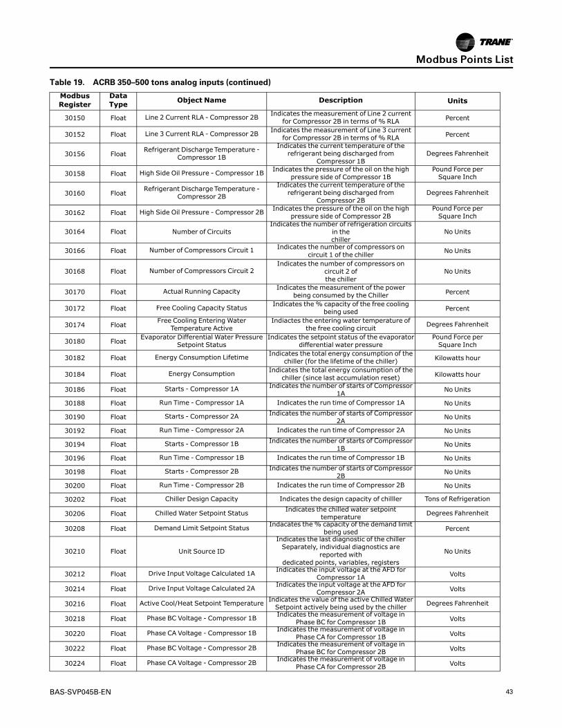
BAS-SVP045B-EN 43
Table 19. ACRB 350–500 tons analog inputs (continued)
ModbusRegister
DataType Object Name Description Units
30150 Float Line 2 Current RLA - Compressor 2B Indicates the measurement of Line 2 currentfor Compressor 2B in terms of % RLA Percent
30152 Float Line 3 Current RLA - Compressor 2B Indicates the measurement of Line 3 currentfor Compressor 2B in terms of % RLA Percent
30156 FloatRefrigerant Discharge Temperature -
Compressor 1B
Indicates the current temperature of therefrigerant being discharged from
Compressor 1BDegrees Fahrenheit
30158 Float High Side Oil Pressure - Compressor 1B Indicates the pressure of the oil on the highpressure side of Compressor 1B
Pound Force perSquare Inch
30160 FloatRefrigerant Discharge Temperature -
Compressor 2B
Indicates the current temperature of therefrigerant being discharged from
Compressor 2BDegrees Fahrenheit
30162 Float High Side Oil Pressure - Compressor 2B Indicates the pressure of the oil on the highpressure side of Compressor 2B
Pound Force perSquare Inch
30164 Float Number of CircuitsIndicates the number of refrigeration circuits
in thechiller
No Units
30166 Float Number of Compressors Circuit 1 Indicates the number of compressors oncircuit 1 of the chiller No Units
30168 Float Number of Compressors Circuit 2Indicates the number of compressors on
circuit 2 ofthe chiller
No Units
30170 Float Actual Running Capacity Indicates the measurement of the powerbeing consumed by the Chiller Percent
30172 Float Free Cooling Capacity Status Indicates the% capacity of the free coolingbeing used Percent
30174 FloatFree Cooling Entering Water
Temperature ActiveIndiactes the entering water temperature of
the free cooling circuit Degrees Fahrenheit
30180 FloatEvaporator Differential Water Pressure
Setpoint StatusIndicates the setpoint status of the evaporator
differential water pressurePound Force perSquare Inch
30182 Float Energy Consumption Lifetime Indicates the total energy consumption of thechiller (for the lifetime of the chiller) Kilowatts hour
30184 Float Energy Consumption Indicates the total energy consumption of thechiller (since last accumulation reset) Kilowatts hour
30186 Float Starts - Compressor 1A Indicates the number of starts of Compressor1A No Units
30188 Float Run Time - Compressor 1A Indicates the run time of Compressor 1A No Units
30190 Float Starts - Compressor 2A Indicates the number of starts of Compressor2A No Units
30192 Float Run Time - Compressor 2A Indicates the run time of Compressor 2A No Units
30194 Float Starts - Compressor 1B Indicates the number of starts of Compressor1B No Units
30196 Float Run Time - Compressor 1B Indicates the run time of Compressor 1B No Units
30198 Float Starts - Compressor 2B Indicates the number of starts of Compressor2B No Units
30200 Float Run Time - Compressor 2B Indicates the run time of Compressor 2B No Units
30202 Float Chiller Design Capacity Indicates the design capacity of chilller Tons of Refrigeration
30206 Float Chilled Water Setpoint Status Indicates the chilled water setpointtemperature Degrees Fahrenheit
30208 Float Demand Limit Setpoint Status Indacates the% capacity of the demand limitbeing used Percent
30210 Float Unit Source ID
Indicates the last diagnostic of the chillerSeparately, individual diagnostics are
reported withdedicated points, variables, registers
No Units
30212 Float Drive Input Voltage Calculated 1A Indicates the input voltage at the AFD forCompressor 1A Volts
30214 Float Drive Input Voltage Calculated 2A Indicates the input voltage at the AFD forCompressor 2A Volts
30216 Float Active Cool/Heat Setpoint Temperature Indicates the value of the active Chilled WaterSetpoint actively being used by the chiller Degrees Fahrenheit
30218 Float Phase BC Voltage - Compressor 1B Indicates the measurement of voltage inPhase BC for Compressor 1B Volts
30220 Float Phase CA Voltage - Compressor 1B Indicates the measurement of voltage inPhase CA for Compressor 1B Volts
30222 Float Phase BC Voltage - Compressor 2B Indicates the measurement of voltage inPhase BC for Compressor 2B Volts
30224 Float Phase CA Voltage - Compressor 2B Indicates the measurement of voltage inPhase CA for Compressor 2B Volts
MMooddbbuuss PPooiinnttss LLiisstt

44 BAS-SVP045B-EN
Table 19. ACRB 350–500 tons analog inputs (continued)
ModbusRegister
DataType Object Name Description Units
30226 Float Average Line Current Circuit 1 Indicates the average current, reported inCircuit 1
Amps
30228 Float Average Line Current Circuit 2 Indicates the average current, reported inCircuit 2
Amps
30230 Float Average Line Voltage Circuit 1 Indicates the average voltage, line-to-linereported in Circuit 1 Volts
30232 Float Average Line Voltage Circuit 2 Indicates the average voltage, line-to-linereported in Circuit 2 Volts
30234 Float Line Current L1 Circuit 1 Indicates the current for line/leg 1 of Circuit 1 Amps
30236 Float Line Current L2 Circuit 1 Indicates the current for line/leg 2 of Circuit 1 Amps
30238 Float Line Current L3 Circuit 1 Indicates the current for line/leg 3 of Circuit 1 Amps
30240 Float Line Current L1 Circuit 2 Indicates the current for line/leg 1 of Circuit 2 Amps
30242 Float Line Current L2 Circuit 2 Indicates the current for line/leg 2 of Circuit 2 Amps
30244 Float Line Current L3 Circuit 2 Indicates the current for line/leg 3 of Circuit 2 Amps
30246 Float Voltage L1-L2 Circuit 1 Indicates the voltage between line/leg L1 andL2 of Circuit 1 Volts
30248 Float Voltage L2-L3 Circuit 1 Indicates the voltage between line/leg L2 andL3 of Circuit 1 Volts
30250 Float Voltage L1-L3 Circuit 1 Indicates the voltage between line/leg L1 andL3 of Circuit 1 Volts
30252 Float Voltage L1-L2 Circuit 2 Indicates the voltage between line/leg L1 andL2 of Circuit 2 Volts
30254 Float Voltage L2-L1 Circuit 2 Indicates the voltage between line/leg L2 andL3 of Circuit 2 Volts
30256 Float Voltage L1-L3 Circuit 2 Indicates the voltage between line/leg L1 andL3 of Circuit 2 Volts
30258 Float Total Real Power Indicates the total real power reported Kilowatts
30260 Float Line Frequency Circuit 1 Indicates the estimated input frequency forCircuit 1 No Units
30262 Float Line Frequency Circuit 2 Indicates the estimated input frequency forCircuit 2 No Units
30264 Float Power Factor Circuit 1 Indicates the reported power factor for Circuit1 No Units
30266 Float Power Factor Circuit 2 Indicates the reported power factor for Circuit2 No Units
30268 Float Power Demand Circuit 1 Indicates the reported power demand forCircuit 1 Kilowatts
30270 Float Power Demand Circuit 2 Indicates the reported power demand forCircuit 2 Kilowatts
Table 20. ACRB 350–500 tons analog values
ModbusRegister Data Type Object Name Description Units
40010 Float Chilled Water Setpoint
The value is normally provided by the BAS to send theChilled Water Setpoint.
The value is subject to arbitration logic in thecontroller, in which case it may or may not be used for
control purposes
Degrees Fahrenheit
40012 Float Demand Limit Setpoint
The value is normally provided by the BAS to send theDemand Limit Setpoint.
The value is subject to arbitration logic in thecontroller, in which case it may or may not be used for
control purposes
Percent
Table 21. ACRB 350–500 tons binary inputs
ModbusRegister Data Type Object Name Description Object States
33010 Signed Integer 16-bit Run EnableIndicates that chiller is available to run or is
currently running0 = Run Not Enabled1 = Run Enabled
33011 Signed Integer 16-bit Local Setpoint Control Indicates the which setpoint is used for controlpurposes, Remote (BAS) or Local
0 = Remote control1 = Local control
33012 Signed Integer 16-bit Limit Mode RelayStatus
Indicates the status of the chiller limit relay 0 = Off1 = On
33013 Signed Integer 16-bit Chiller Running StateIndicates whether the chiller is on (currently doingeither cooling) or is considered off(not currently
doing cooling)
0 = Off1 = On
MMooddbbuuss PPooiinnttss LLiisstt

BAS-SVP045B-EN 45
Table 21. ACRB 350–500 tons binary inputs (continued)
ModbusRegister Data Type Object Name Description Object States
33014 Signed Integer 16-bit Maximum Capacity Indicates the status of the maximum capacityrelay
0 = Off1 = On
33016 Signed Integer 16-bit Manual Override Exists Indicated a manual override is present 0 = Off1 = On
33017 Signed Integer 16-bit Compressor 1A Status Indicates running state fo Compressor 1A 0 = Off1 = Running
33018 Signed Integer 16-bit Compressor 2A Status Indicates running state fo Compressor 2A 0 = Off1 = Running
33019 Signed Integer 16-bit Emergency Stop Indicates the status of the emergency stopfunction of the chiller
0 = Auto1 = Emergency Stop -Manual Reset Required
33020 Signed Integer 16-bit Evaporator WaterPump Request
Indicates a request from the chiller to turn on theEvaporator Water Pump
0 = Off1 = On
33021 Signed Integer 16-bit Evaporator Water FlowStatus
Indicates the flow of water through evaporator 0 = No Flow1 = Flow
33022 Signed Integer 16-bit Compressor 1B Status Indicates running state of Compressor 1B 0 = Off1 = Running
33023 Signed Integer 16-bit Compressor 2B Status Indicates running state of Compressor 2B 0 = Off1 = Running
33024 Signed Integer 16-bit Free Cooling Active Indicated the free cooling mode is active 0 = Inactive1 = Active
33026 Signed Integer 16-bit Diagnostic Present Indicates whether diagnostic present 0 = Normal1 = In Alarm
33027 Signed Integer 16-bit Diagnostic ShutdownPresent
Indicates chiller is shut down due to diagnostics 0 = Normal1 = In Alarm
33028 Signed Integer 16-bit Diagnostic: ManualReset Required
Indicates when a diagnostic exists that requiresmanual reset
0 = Normal1 = In Alarm
33029 Signed Integer 16-bit Diagnostic: LocalManual Reset Required
Indicates when a diagnostic exists that requiresmanual reset [Local only]
0 = Normal1 = In Alarm
33030 Signed Integer 16-bit Diagnostic Present:Information
Indicates whether diagnostic present withInformation Category
0 = Normal1 = In Alarm
33031 Signed Integer 16-bit Diagnostic Present:Advisory
Indicates whether diagnostic present with WarningCategory
0 = Normal1 = In Alarm
33032 Signed Integer 16-bit Diagnostic Present:Critical
Indicates whether diagnostic present with CriticalCategory
0 = Normal1 = In Alarm
33033 Signed Integer 16-bit Diagnostic Present:Service Required
Indicates whether diagnostic present with ServiceRequired Category
0 = Normal1 = In Alarm
33034 Signed Integer 16-bit External Auto StopInput Status
Indicates the status of the externally-wired auto/stop input
0 = Stop1 = Auto
33035 Signed Integer 16-bit Front Panel Auto Stop Indicates the auto/stop status of the Front Panel 0 = Stop1 = Auto
33036 Signed Integer 16-bit Noise ReductionRequest Active Indicates wherther Noise Reduction active 0 = Off
1 = On
33037 Signed Integer 16-bit Circuit 1 Lockout FrontPanel
Indicates the lockout state of Circuit 1 Comprosserfrom Front Panel
0 = Normal1 = Locked Out
33038 Signed Integer 16-bit Circuit 2 Lockout FrontPanel
Indicates the lockout state of Circuit 2 Comprosserfrom Front Panel
0 = Normal1 = Locked Out
33039 Signed Integer 16-bit Circuit 1 LockoutExternal
Indicates the lockout state of Circuit 1 Comprosserfrom External
0 = Normal1 = Locked Out
33040 Signed Integer 16-bit Circuit 2 LockoutExternal
Indicates the lockout state of Circuit 2 Comprosserfrom External
0 = Normal1 = Locked Out
33041 Signed Integer 16-bit Circuit 1 Lockout Active Indicates the lockout state of Circuit 1 Comprosser 0 = Normal1 = Locked Out
33042 Signed Integer 16-bit Circuit 2 Lockout Active Indicates the lockout state of Circuit 2 Comprosser 0 = Normal1 = Locked Out
Table 22. ACRB 350–500 tons binary value
ModbusRegister Data Type Object Name Description Object
States
43010Signed
Integer 16-bit Reset Diagnostic Normally used by the BMS to initiate a requestto reset any controller diagnostics
0 = Normal1 = Reset
43011Signed
Integer 16-bitNoise ReductionRequest BAS
Normally used by the BMS to command the chiller to enter a mode ofoperation where the noise of the unit is reduced
0 = Normal1 = ReduceNoise
43012Signed
Integer 16-bit Circuit 1 Lockout BAS Normally used by the BMS to lockout the Circuit-1 Compressor0 = Normal1 = Locked
Out
MMooddbbuuss PPooiinnttss LLiisstt

46 BAS-SVP045B-EN
Table 22. ACRB 350–500 tons binary value (continued)
ModbusRegister Data Type Object Name Description Object
States
43013Signed
Integer 16-bit Circuit 2 Lockout BAS Normally used by the BMS to lockout the Circuit-2 Compressor0 = Normal1 = Locked
Out
43017Signed
Integer 16-bitEnergy Consumption
ResetNormally used by the BMS to reset the energy consumption
accumulated total
0 =Accumulat-
ing1 = Reset
43018Signed
Integer 16-bitChiller Auto StopCommand BAS
Normally used by the BMS to command the chiller to start running ifoperating conditions are satisfied, or to stop the chiller from running.
0 = Stop1 = Auto
43019Signed
Integer 16-bitFree Cooling Auto Stop
Command BAS
Normally used the BMS to command the chiller to allow free coolingmode if conditions are satisfied, or to stop the free cooling mode from
operating.
0 = Stop1 = Auto
43020Signed
Integer 16-bitFree Cooling
Compressor LockoutNormally used by the BMS to lockout the Compressor while in free
cooling mode
0 = Normal1 = Locked
Out
Table 23. ACRB 350–500 tons multi-state inputs
ModbusRegister Data Type Object Name Description Object States
32010 Unsigned Integer 16-bit Running Mode Indicates the operating mode of the chiller
1 = Cool2 = Heat
3= Ice Making4= Free Cooling
32011 Unsigned Integer 16-bit Operating Mode Indicates the chiller refrigerant type
1 = R-112 = R-123= R-224= R-1235 = R-134a6 = R-407C7 = R-410A8 = R-1139 = R-11410 = R-50011 = R-50212 = R-404A13 = R-513A
14 = R-1233zd(E)15 = R-514A
16 = R-1234ze(E)
32012 Unsigned Integer 16-bit Refrigerant Type Indicates the cooling Type of chiller 1 = Water Cooled2 = Air Cooled
32013 Unsigned Integer 16-bit Cooling Type Indicates the location that the chiller wasmanufactured
1 = Field Applied2 = La Crosse3= Pueblo4= Charmes5 = Rushville6 = Macon7 =Waco
8 = Lexington9 = Forsyth
10 = Clarksville11 = Ft. Smith12 = Penang13 = Colchester14 = Curitiba15 = Taicang16 = Taiwan17 = Epinal18 = Golbey
MMooddbbuuss PPooiinnttss LLiisstt

BAS-SVP045B-EN 47
Table 23. ACRB 350–500 tons multi-state inputs (continued)
ModbusRegister Data Type Object Name Description Object States
32014 Unsigned Integer 16-bit Manufacture Location Indicates the model information of chiller
1 = CVHF2 = CVGF3= CVHS4= RTAE5 = RTAF6 = RTHA7 = RTHB8 = RTHC9 = RTHD10 = RTWE11 = CTVD12 = CVR13 = CVHH14 = CDHH15 = VMAX16 = GVAF17 = RTWF18 = RTHF19 = RTAC20 = CVHM21 = RTAG22 = CGAF23 = RTXG24 = GVWF25 = HDWA26 = CMAC27 = IPAK28 = CXAF29 = ACSA30 = RTSF31 = HSWA32 = ACRA33 = RTEG34 = ACXA35 = CMAF
36 = ACRB Large37 = ACRB Small
32015 Unsigned Integer 16-bit Model Information[GEN2]
1 = BAS2 = External3 = Front Panel
32016 Unsigned Integer 16-bit Chiller SetpointSource
Indicates the selected setpoint source forcontrol purpose
1 = BAS2 = External3 = Front Panel
Table 24. ACRB 350–500 tons multi-state valuesModbusRegister Data Type Object Name Description Object States
42010 Unsigned Integer 16-bit Chiller Mode Command BAS Normally used by the BMS to command thechiller Mode
1 = Cool2 = Heat
3= Ice Making4= Free Cooling
MMooddbbuuss PPooiinnttss LLiisstt

48 BAS-SVP045B-EN
Recycled PointsThe Symbio™ 800 controller ships from the factory pre-configured for the specific unitapplication. The points of the communicated interface (BACnet, Modbus, or LonTalk) vary basedon the unit configuration. Only those points pertinent to that configuration are included in theinterface.
Example: When the unit is configured for only two compressors, any points associated withcompressors three and four are not be displayed on the Touch Screen interface or browser-based Web user interface. When configuration changes are made in the field, the points in thecommunication interface change accordingly to align with those features or user-added points.
Figure 22. Points
Any of the factory-provided points can be removed from the communication interface through afeature known as recycling. When the user selects and deletes a factory point, that point ismoved to Recycled Points and is removed from the interface. This feature offers technicians theability to strategically provide only those interface points desired for a specific project orinstallation.
To remove a point from the interface:
1. On the left-hand navigation, select PPooiinnttss.
2. Each of the points are grouped by their native type (analog, binary or multi-state), and input,output, or value. Select the appropriate group at the top of the page.
3. Select one or more points from the list and select AAccttiioonnss...... || DDeelleettee.
MMooddbbuuss PPooiinnttss LLiisstt

BAS-SVP045B-EN 49
Figure 23. Delete points
NNoottee:: User-created points cannot be recycled. Instead, when the user selects and deletes user-created points, those points are permanently removed from the controller. Should the userdecide later that one or more of the deleted user points are needed, they will need to berecreated.
To restore recycled points:
1. Navigate to the RReeccyycclleedd PPooiinnttss tab on the Points page.
2. Select one or more points to be restored, then click RReessttoorree.
3. Once the restore process is complete, the restored points are moved back to the appropriatetab depending on point type. The recycled points also appear in the communicated interfaceonce they are restored.
MMooddbbuuss PPooiinnttss LLiisstt

50 BAS-SVP045B-EN
Figure 24. Recycled points tab
MMooddbbuuss PPooiinnttss LLiisstt

BAS-SVP045B-EN A–1
Appendix A. ArbitrationThe Symbio™ 800 controller includes arbitration logic for several points. For each read/writepoint designated as “BAS”, an associated “Arbitration” point determines the behavior of thatcommunicated data compared to the local hardwired (or wireless) sensor and a default value.
As shown in Figure 25, p. A–1, the arbitrator considers all possible sources of the provided data,including Building Management Systems (BMS), local, and default. Each potential source isdefined at a pre-determined, fixed priority. When the arbitration method is selected as full/auto,the BMS value is used instead of the local or default values.
The point designator with the arbitrator suffix includes the full priority array, allowing the user tosee the value associated with all potential sources considered in the logic. The active pointreflects the result of the arbitration logic.
Because the arbitrated points are normally associated with sensors, the default value is invalid,meaning the value must be provided either by the BMS or the local sensor.
Figure 25. Arbitration method - full/auto
When the Arbitration Method is selected as local, the BMS value is ignored and local value isused instead. Though the arbitration logic still considers all inputs, any values sent by the BMSare effectively ignored.
Figure 26. Arbitration method - local
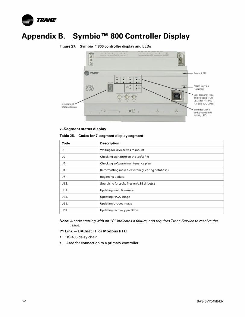
B–1 BAS-SVP045B-EN
Appendix B. Symbio™™ 800 Controller DisplayFigure 27. Symbio™™ 800 controller display and LEDs
77––SSeeggmmeenntt ssttaattuuss ddiissppllaayy
Table 25. Codes for 7–segment display segment
Code Description
U0. Waiting for USB drives to mount
U2. Checking signature on the .scfw file
U3. Checking software maintenance plan
U4. Reformatting main filesystem (clearing database)
U5. Beginning update
U12. Searching for.scfw files on USB drive(s)
U51. Updating main firmware
U54. Updating FPGA image
U55. Updating U-boot image
U57. Updating recovery partition
NNoottee:: A code starting with an “F” indicates a failure, and requires Trane Service to resolve theissue.
PP11 LLiinnkk —— BBAACCnneett TTPP oorr MMooddbbuuss RRTTUU
• RS-485 daisy chain
• Used for connection to a primary controller
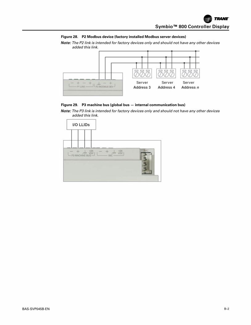
BAS-SVP045B-EN B–2
Figure 28. P2 Modbus device (factory installed Modbus server devices)
NNoottee:: The P2 link is intended for factory devices only and should not have any other devicesadded this link.
Server Server Server
Figure 29. P3 machine bus (global bus — internal communication bus)
NNoottee:: The P3 link is intended for factory devices only and should not have any other devicesadded this link.
SSyymmbbiioo™™ 880000 CCoonnttrroolllleerr DDiissppllaayy

B–3 BAS-SVP045B-EN
Figure 30. IMC link terminations for optional Air-Fi and expansion module (XM30)
For more information on Expansion Module wiring reference BAS-SVX46* – Expansion ModuleInstallation Operation and Maintenance Manual.
Figure 31. (4) USB connectors
SSyymmbbiioo™™ 880000 CCoonnttrroolllleerr DDiissppllaayy

BAS-SVP045B-EN B–4
The controller automatically detects devices on any of the ports (not port specific). The controllerships with all ports enabled, but they can be disabled via the Web interface.
NNoottee:: The USB ports are not to be used for any devices that are not Trane approved, such ascellular phones.
Figure 32. Ethernet port 2
Touch Screen Display
NNoottee:: Ethernet Port 2 is for use with the Touch Screen display only. Communication to otherdevices is not supported.
SSyymmbbiioo™™ 880000 CCoonnttrroolllleerr DDiissppllaayy

Trane - by Trane Technologies (NYSE: TT), a global innovator - creates comfortable, energy efficientindoor environments for commercial and residential applications. For more information, please visittrane.com or tranetechnologies.com.
Trane has a policy of continuous product and product data improvements and reserves the right to change design and specifications withoutnotice. We are committed to using environmentally conscious print practices.
BAS-SVP045B-EN 01 Apr 2021
Supersedes BAS-SVP045A-EN (October 2020) ©2021 Trane