User Manual Anybus BACnet to Modbus Gateway
17
HALMSTAD • CHICAGO • KARLSRUHE • TOKYO • BEIJING • MILANO • MULHOUSE • COVENTRY • PUNE • COPENHAGEN HMS Industrial Networks Mailing address: Box 4126, 300 04 Halmstad, Sweden Visiting address: Stationsgatan 37, Halmstad, Sweden Connecting Devices TM E-mail: [email protected] www.anybus.com User Manual Anybus BACnet to Modbus Gateway Doc: HMSI-27-274 Rev. 1.00
Transcript of User Manual Anybus BACnet to Modbus Gateway

HALMSTAD • CHICAGO • KARLSRUHE • TOKYO • BEIJING • MILANO • MULHOUSE • COVENTRY • PUNE • COPENHAGEN
HMS Industrial NetworksMailing address: Box 4126, 300 04 Halmstad, SwedenVisiting address: Stationsgatan 37, Halmstad, Sweden
Connecting DevicesTM
E-mail: [email protected] www.anybus.com
User Manual
Anybus BACnet to Modbus GatewayDoc: HMSI-27-274
Rev. 1.00

Important User Information
This document is intended to provide a good understanding of the functionality offered by the Anybus BACnet to Modbus Gateway. The document only describes the features that are specific to the Anybus BACnet to Modbus Gateway.
The reader of this document is expected to be familiar with high level software design, and communication sys-tems in general.
Liability
Every care has been taken in the preparation of this manual. Please inform HMS Industrial Networks AB of any inaccuracies or omissions. The data and illustrations found in this document are not binding. We, HMS Industrial Networks AB, reserve the right to modify our products in line with our policy of continuous product development. The information in this document is subject to change without notice and should not be considered as a commit-ment by HMS Industrial Networks AB. HMS Industrial Networks AB assumes no responsibility for any errors that may appear in this document.
There are many applications of this product. Those responsible for the use of this device must ensure that all the necessary steps have been taken to verify that the applications meet all performance and safety requirements in-cluding any applicable laws, regulations, codes, and standards.
HMS Industrial Networks AB will under no circumstances assume liability or responsibility for any problems that may arise as a result from the use of undocumented features, timing, or functional side effects found outside the documented scope of this product. The effects caused by any direct or indirect use of such aspects of the product are undefined, and may include e.g. compatibility issues and stability issues.
The examples and illustrations in this document are included solely for illustrative purposes. Because of the many variables and requirements associated with any particular implementation, HMS Industrial Networks AB cannot assume responsibility for actual use based on these examples and illustrations.
Trademark Acknowledgements
Anybus ® is a registered trademark of HMS Industrial Networks AB. All other trademarks are the property of their respective holders.
Warning: This is a class A product. in a domestic environment this product may cause radio interference in which case the user may be required to take adequate measures.
ESD Note: This product contains ESD (Electrostatic Discharge) sensitive parts that may be damaged if ESD control procedures are not followed. Static control precautions are required when handling the prod-uct. Failure to observe this may cause damage to the product.
Anybus BACnet to Modbus Gateway User Manual
Copyright© HMS Industrial Networks AB
Anybus BACnet to Modbus Gateway User Manual
Doc: HMSI-27-274, Rev: 1.00
Important User InformationLiability........................................................................................................................................... 2Intellectual Property Rights ............................................................................................................... 2Trademark Acknowledgements......................................................................................................... 2
Preface About This Document
Related Documents .................................................................................................................................. 4
Document History ................................................................................................................................... 4
Conventions & Terminology .................................................................................................................. 4
Support....................................................................................................................................................... 4
Chapter 1 Introduction
Chapter 2 Configuration
Accessing the Configuration Pages........................................................................................................ 8System.............................................................................................................................................. 8BACnet........................................................................................................................................... 8Modbus............................................................................................................................................ 8
Chapter 3 Managing Modbus Devices
Adding a Device ..................................................................................................................................... 10
Modifying, Copying and Deleting Devices......................................................................................... 10
Mapping Status ....................................................................................................................................... 11
Upload Profile ......................................................................................................................................... 11
Chapter 4 Using Virtual BACnet Routing
Chapter 5 Applications
Application #1 - Two Virtual Networks ............................................................................................ 13
Application #2 - Mixing Modbus TCP and Serial ............................................................................ 14
Application #3 - Modbus Serial to TCP Routing ............................................................................. 15
Application #4 - Subnetted IP Network ............................................................................................ 16
Appendix A Technical Specifications
Table of Contents
Table of Contents

Anybus BACnet to Modbus Gateway User Manual Doc: HMSI-27-274, Rev: 1.00
Preface
P. About This Document
For more information, documentation etc., please visit the HMS website www.anybus.com.
P.1 Related Documents
P.2 Document History
Revision List
P.3 Conventions & Terminology
The following conventions are used throughout this manual:
• Numbered lists provide sequential steps
• Bulleted lists provide information, not procedural steps
P.4 Support
For general contact information and support, please refer to the contact and support pages at www.hms-networks.com.
Document Author
Anybus BACnet to Modbus Gateway Installation Guide SDa
Revision Date Author(s) Chapter(s) Description
1.00 September 2014 SDa - First official release

Anybus BACnet to Modbus Gateway User Manual Doc: HMSI-27-274, Rev: 1.00
Chapter 1
1. Introduction
The Anybus BACnet to Modbus Gateway is housed in a metal case that mounts on 35-mm DIN-rail. Power is from a 24 VAC/VDC (± 10%) source. The half-wave rectified power supply allows sharing of power with other half-wave devices.
The optically-isolated serial port allows for connection to either 2-wire or 3-wire RS-485 networks, using a removable 5-pin terminal block. Up to 30 RS-485 Modbus devices can share the serial bus at data rates 2.4 to 115.2 kbps.
The Ethernet port provides a shielded RJ-45 connector. Auto-negotiation and Auto-MDIX automati-cally matches connections to the attached equipment, thus allowing either CAT5 straight-through or crossover cable to be used for connecting to the BACnet/IP or Modbus TCP network at 10/100 Mbps.
A resident web server allows for commissioning, and troubleshooting via a standard web browser. A reset switch is provided for returning to the factory default IP address. LED indicators provide commu-nication status on both the Ethernet and serial ports.
1.1 Hardware Overview
Reset IP AddressPress to reset gateway IP address to the default.
Ethernet Port10/100 Mbps Ethernet port with auto-negotiation and Auto-MDIX. Protocols supported include HTTP, IP, UDP, TCP, Modbus TCP and BACnet/IP
Modbus PortRemovable 3-wire isolated RS-485 connection with support for 2-wire non-isolated devices.
Modbus LED:sMonitoring of Modbus transmit and receive activity.
Redundant Power Input24 V AC/DC 10 VA half-wave regulated design allows power sharing with other half-wave devices.
Power LEDIndicates power is applied.
(Intended for Class II circuits only)
Power DC AC
Input voltage: 24 V 24 V
Input power: 6 W 10 VA
Input frequency: N/A 47–63 Hz
Anybus BACnet to Modbus Gateway User Manual Doc: HMSI-27-274, Rev: 1.00
Chapter 2
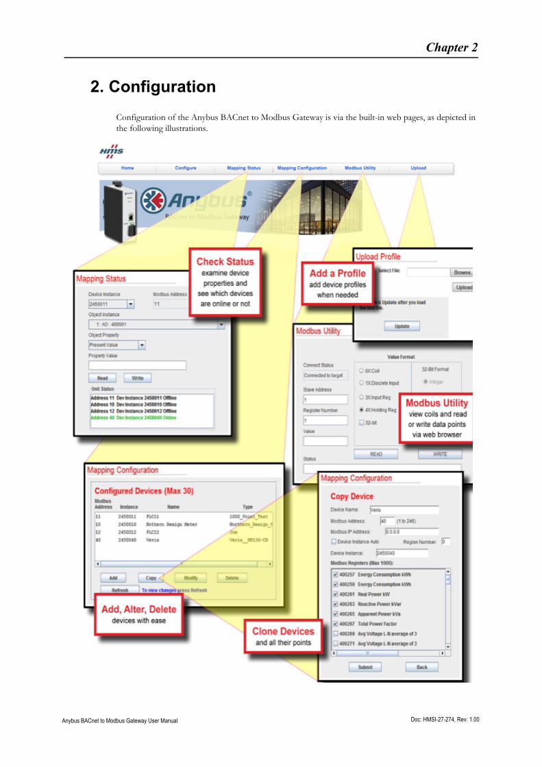
2. Configuration
Configuration of the Anybus BACnet to Modbus Gateway is via the built-in web pages, as depicted in the following illustrations.

Configuration 7
Anybus BACnet to Modbus Gateway User Manual Doc: HMSI-27-274, Rev: 1.00

Configuration 8
Anybus BACnet to Modbus Gateway User Manual Doc: HMSI-27-274, Rev: 1.00
2.1 Accessing the Configuration Pages
The configuration pages can be accessed via a standard web browser using Java 6 or later. The Anybus BACnet to Modbus Gateway is shipped with a default private IP address, which is 192.168.92.68. Enter this address in the browser to begin configuration.
There are 3 main areas that require configuration.
2.1.1 System
In all likelihood, the default IP address and subnet mask for the gateway will need to be changed, but it is always possible to reset the IP address to the default settings without losing any other configuration data. A name can be provided for the Anybus BACnet to Modbus Gateway. If there is an IP router on the attached Ethernet network, provide this IP address as the Gateway Address when configuring the System settings.
2.1.2 BACnet
The Anybus BACnet to Modbus Gateway must be assigned a unique device instance number independ-ent of any other assignments. The UDP port is typically the default registered BACnet port 0xBAC0. Only under special circumstances does this need to be changed.
If the Anybus BACnet to Modbus Gateway is to be installed on a subnetted BACnet internetwork, it will be necessary for the gateway to register as a Foreign Device with a BACnet/IP Broadcast Manage-ment Device (BBMD), if none exists on the gateway’s subnet. If this is the case, enter the IP address of a known BBMD, thereby invoking Foreign Device Registration with this BBMD. This is why the gateway address must be entered in the system settings. By registering as a foreign device, the Anybus BACnet to Modbus Gateway will be able to receive broadcast messages originating from other subnets. A BBMD registration time must be entered so that registration is continuously renewed on a periodic basis.
The final setting is the Virtual Network address. This is the unique BACnet network number assigned to the attached Modbus devices.
2.1.3 Modbus
The last section in the Configure Settings screen deals only with Modbus serial devices. The first decision concerns setting a baud rate between 2400 and 115200, although 19200 is the default. The next is to select Modbus RTU or Modbus ASCII. Modbus RTU is more common and is the default. Next is the Parity setting, which is recommended to be set to NONE, although EVEN is the default. If no parity is selected, an extra STOP bit is automatically added, so as to not change the frame length. Whatever the settings used, they MUST apply to ALL attached Modbus devices.
There are other settings that should not be touched unless there is good reason. Time settings are in milliseconds. Command Timeout is the time the master waits for a response from a slave. The Inter Scan Delay is the time between each polling cycle. The Offline Poll Period is the time the master will wait before trying to contact an offline slave. The Consecutive RD Delay is the amount of time the master waits when polling the same device with consecutive reads. If the slave device is capable of responding to a block read of consecutively numbered points, the Max Consecutive RD can be limited by this number.

Configuration 9
Anybus BACnet to Modbus Gateway User Manual Doc: HMSI-27-274, Rev: 1.00
Mapping Modbus Points to BACnet
Modbus data is considered as divided in four memory blocks - coils, discrete inputs, input registers and holding registers. Discrete inputs and coils are considered 1-bit points, while input reg-isters and holding registers are 16-bit points. So, 1-bit points would be assigned either a BACnet BI or BO object type, while 16-bit points would be either an AI or AO. If the point was read-only, then it would be considered a BACnet input. All read/write points would be considered outputs. Using this convention, the following mapping rules apply when generating device profiles:
• Modbus Coils become BOs
• Modbus Discrete Inputs become BIs
• Modbus Input Registers become AIs
• Modbus Holding Registers become AOs
There is however, an exception to these rules. It is possible for a holding register to be packed as in-dividual status bits or control points that require extraction. When generating the device profile, these are broken out as individual BOs or BIs, instead of as one AO. Object instance numbers are then assigned sequentially for each identified Modbus point.

Anybus BACnet to Modbus Gateway User Manual Doc: HMSI-27-274, Rev: 1.00
Chapter 3
3. Managing Modbus Devices
Once the Anybus BACnet to Modbus Gateway is properly configured, Modbus device profiles can be added for each connected Modbus device. The process for adding devices is similar for Modbus Serial or Modbus TCP devices.
3.1 Adding a Device
By clicking on the Mapping Configuration tab you will be presented with a Configured Devices box showing all Modbus devices that are currently being assessed by the Anybus BACnet to Modbus Gate-way. Clicking on any of the devices listed will display a Device Information box showing the device pro-file of that particular device. The device profile lists all available Modbus points, with each entry having its own check-box. A checked box means that the associated point is being included in the gateway’s scan list.
When viewing the Configured Devices box, a Modbus device can be added by clicking the Add button. From the drop-down Device Profile menu, select the appropriate device profile for the device to be added. The selected profile with pre-checked boxes will be added. You can add or delete the points of interest at any time before submitting the device to the scan list. Next, assign the Modbus slave address, in the range 1-246. If the device is a Modbus serial device, leave the Modbus IP Address at the default 0.0.0.0 setting. If the device is a Modbus TCP device, enter its IP address, as well as the slave address. If the Modbus TCP device is on a different subnet to that of the Anybus BACnet to Modbus Gateway, communication will be possible if IP routers are installed on the respective subnets.
A unique BACnet device instance number will need to be assigned to each connected Modbus device, and the Anybus BACnet to Modbus Gateway has a scheme to make assignments easier. Note that the Device Instance Auto box is checked, meaning that the gateway will attempt to automatically assign unique BACnet device instances to each Anybus BACnet to Modbus Gateway being installed. The following digit is determined by the Region Number, in the range 0-9.
The final digits are the Modbus slave address. If there is only one Anybus BACnet to Modbus Gateway on the BACnet internetwork, then there is no need to increment the Region Number from the default value of zero. If more than one Anybus BACnet to Modbus Gateway is being used in the same system, increment the Region Number for each added gateway, up to 9, to ensure that no duplicate BACnet device instances are generated.
For more than 10 Anybus BACnet to Modbus Gateways, it will be necessary to enter the BACnet device instance manually. Uncheck the Device Instance Auto box and enter a unique number in the range 0-4194302.
To complete the configuration, you can enter a name for the device you added on the top line. Once all entries are made, click Submit and then Back to return to the Configured Devices box. Once there, refresh the box and you will see your new device.
3.2 Modifying, Copying and Deleting Devices
From the Configured Devices box, you can modify settings in a device, and copy a device if multiple instances of the same device are to be used. It is also possible to delete a device.

Managing Modbus Devices 11
Anybus BACnet to Modbus Gateway User Manual Doc: HMSI-27-274, Rev: 1.00
3.3 Mapping Status
By clicking on Mapping Status you can determine the number of Modbus devices that are online, by observing the Unit Status box. To view a particular device, go to the Device Instance drop-down box and select the device. The Modbus address will automatically appear to the right of the device instance. Modbus TCP devices will appear as a combination of IP address and Modbus slave address. Using the Object Instance drop-down box you can scroll through all the objects that are being polled within that device. The first reference is the actual BACnet object instance, which is followed by the object instance type (AI, AO, BI or BO).
The last reference is the Modbus point. After selecting one of the objects, an object property can be selected through the Object Property drop-down. One property of interest would be the Present Value of the object. The present value of all objects can be read by clicking on the Read button, but not all objects can be written by supplying a value and clicking on the Write button. If the object prop-erty cannot be written, the Write button will be greyed out.
3.4 Upload Profile
Standard device profiles are supplied with the device, but new ones are continuously being developed. Newly developed profiles will be posted on the Anybus BACnet to Modbus Gateway support page, at http://www.anybus.com.
If a device profile is not available for your device, HMS supplies tools and instructions on how these can be created. Please see the Step-by-step guide for the Anybus Profile Builder and the support pages.
In addition, HMS will develop or modify an existing device profile based upon customer requests. Wher-ever the source of the new or modified device profile, it must first be loaded onto the customer's com-puter and then uploaded to the Anybus BACnet to Modbus Gateway, following the instructions under the Upload Profile tab.

Anybus BACnet to Modbus Gateway User Manual Doc: HMSI-27-274, Rev: 1.00
Chapter 4
4. Using Virtual BACnet Routing
In the BACnet protocol, physical BACnet devices are assigned unique device instances. In this way, any BACnet device on the same BACnet internetwork can be uniquely identified. Accommodations must be made for non-BACnet compliant devices such as Modbus devices, but the ability to uniquely identify each Modbus device within the BACnet internetwork can be retained thanks to virtual networking.
The Anybus BACnet to Modbus Gateway has one Modbus serial port that can accommodate up to 30 physical Modbus serial devices. Each of the attached devices must be configured for the same baud rate, the same parity, and the same serial protocol – RTU or ASCII. Each device must be assigned a unique slave ID, from 1 to 246. Additionally, the gateway will also support Modbus TCP slave devices connect-ed via Ethernet. The Anybus BACnet to Modbus Gateway functions as a master to all these slave de-vices. Collectively, all the Modbus TCP and Modbus serial devices are assigned virtual BACnet network number during configuration.
Using the concept of virtual BACnet routing, each uniquely addressed Modbus slave device appears as an individual BACnet device, with a unique BACnet device instance assignment. Within this BACnet device is a collection of BACnet objects that relate to Modbus data points. Each Modbus device type requires a device profile, to allow the mapping of Modbus data points to BACnet object instances. HMS maintains a library of common device profiles, with the more popular profiles shipped with the product. Energy meter device profiles from Veris, Northern Design and Continental Control Systems are part of the library, and more are frequently added.
During commissioning, a Modbus device is “added” by selecting the appropriate device profile and as-signing a unique BACnet device instance. Each device profile lists all the available Modbus data points for a particular Modbus device type, along with recommended BACnet object instance designations. A checkbox alongside a data point indicates that this point is to be polled by the Anybus BACnet to Mod-bus Gateway. By default, the most popular registers in each device profile are marked for polling, but the user can add or delete from this list via the web pages. Up to 30 edited device profiles can be added, each with a unique Modbus slave address and BACnet device instance. Each device profile can be the same, or different, depending upon the Modbus device type or the amount of points needing to be scanned. The only restriction is the 30 slot limit and the maximum total polled point count of 1000.
Shown below are three device profiles representing three Modbus devices that will be polled for data while appearing as BACnet devices. Each device has been assigned a unique BACnet device instance. The first two devices are identical and have the same device profile, while the third one is a totally dif-ferent device. Note that the first two devices have different data points checked, demonstrating the flex-ibility in selecting only the points of interest that require polling. To poll multiple identical devices (e.g. energy meters) — edited device profiles can be copied to further speed up commissioning.

Anybus BACnet to Modbus Gateway User Manual Doc: HMSI-27-274, Rev: 1.00
Chapter 5
5. Applications
The following are examples of how the Anybus BACnet to Modbus Gateway can be used in various scenarios.
5.1 Application #1 - Two Virtual Networks
A common application is adding one or more Modbus serial networks to a BACnet system. Each Mod-bus serial network must be configured for the same Modbus serial protocol (RTU or ASCII), the same data rate (2400-115200 baud), and the same parity (ODD, EVEN or NONE).
Ensure that any wiring issues with 2-wire and 3-wire devices are addressed. In the system shown below, two virtual BACnet networks must be assigned - Network 1 and Network 2 - which are separate from the real BACnet network, numbered 3 in this example. If you are using the Device Instance Auto feature to automatically assign device instances, you must select a different Region Number for the two Anybus BACnet to Modbus Gateways, to ensure that no duplicate device instances are generated.
BACnet Client
BACnet/IP Network 3
Modbus Serial - BACnet Network 2
Anybus BACnet toModbus Gateway
Modbus Serial - BACnet Network 1
Anybus BACnet toModbus Gateway
BACnetServer
BACnetServer
BACnetServer
ModbusSlave
ModbusSlave
ModbusSlave
ModbusSlave
ModbusSlave
ModbusSlave

Applications 14
Anybus BACnet to Modbus Gateway User Manual Doc: HMSI-27-274, Rev: 1.00
5.2 Application #2 - Mixing Modbus TCP and Serial
A single Anybus BACnet to Modbus Gateway can handle Modbus TCP devices and Modbus RTU devices simultaneously, as long as the 30 device/1000 polled point limit is maintained. In this application the Modbus TCP connection is known as a "one-armed gateway," because both Modbus TCP and BACnet/IP messages transfer through the same Ethernet port.
Configuration is similar to that of a Modbus serial device. However, this time the IP address of the Modbus TCP device must be entered, as well as a Modbus slave address. There is a potential conflict if using the Device Instance Auto feature and if a connected Modbus TCP device and a connected Mod-bus Serial device happen to use the same slave address. If a conflict is reported by the Anybus BACnet to Modbus Gateway, simply set the device instance manually - or select a different Region Number.
BACnet Client
BACnet/IP Network 3
Modbus Serial - BACnet Network 1
Anybus BACnet toModbus Gateway
As only one Gateway is used in this application, only one virtual BACnet network number is assigned.
ModbusServer
ModbusServer
ModbusServer
Modbus TCP - BACnet Network 1
BACnetServer
BACnetServer
BACnetServer
ModbusSlave
ModbusSlave
ModbusSlave

Applications 15
Anybus BACnet to Modbus Gateway User Manual Doc: HMSI-27-274, Rev: 1.00
5.3 Application #3 - Modbus Serial to TCP Routing
The Anybus BACnet to Modbus Gateway will function inherently as a Modbus serial to Modbus TCP router. This mode requires no mapping configuration, since BACnet is not involved. Modbus TCP de-vices can function as clients, servers or as client/servers. When a Modbus TCP server device is config-ured, it must be assigned a slave address as well as an IP address. When a Modbus TCP client accesses a Modbus TCP server, communication occurs over Ethernet with no involvement from the Anybus BACnet to Modbus Gateway.
However, if a Modbus TCP client communicates with a Modbus serial device, the message is routed through the gateway, to its serial bus. For this application, no configuration is required other than the System and Modbus settings under the Configure Settings tab.
Modbus TCP Client
Modbus TCP
Modbus Serial
Anybus BACnet toModbus Gateway
Modbus TCP
ModbusServer
ModbusServer
ModbusServer
ModbusServer
ModbusServer
ModbusServer
ModbusSlave
ModbusSlave
ModbusSlave
ModbusSlave
Applications 16
Anybus BACnet to Modbus Gateway User Manual Doc: HMSI-27-274, Rev: 1.00
5.4 Application #4 - Sub-netted IP Network
When using IP networks, BACnet client devices, the Anybus BACnet to Modbus Gateway and Modbus TCP devices can all reside on different subnets, interconnected through IP routers. The gateway will still operate under these conditions.
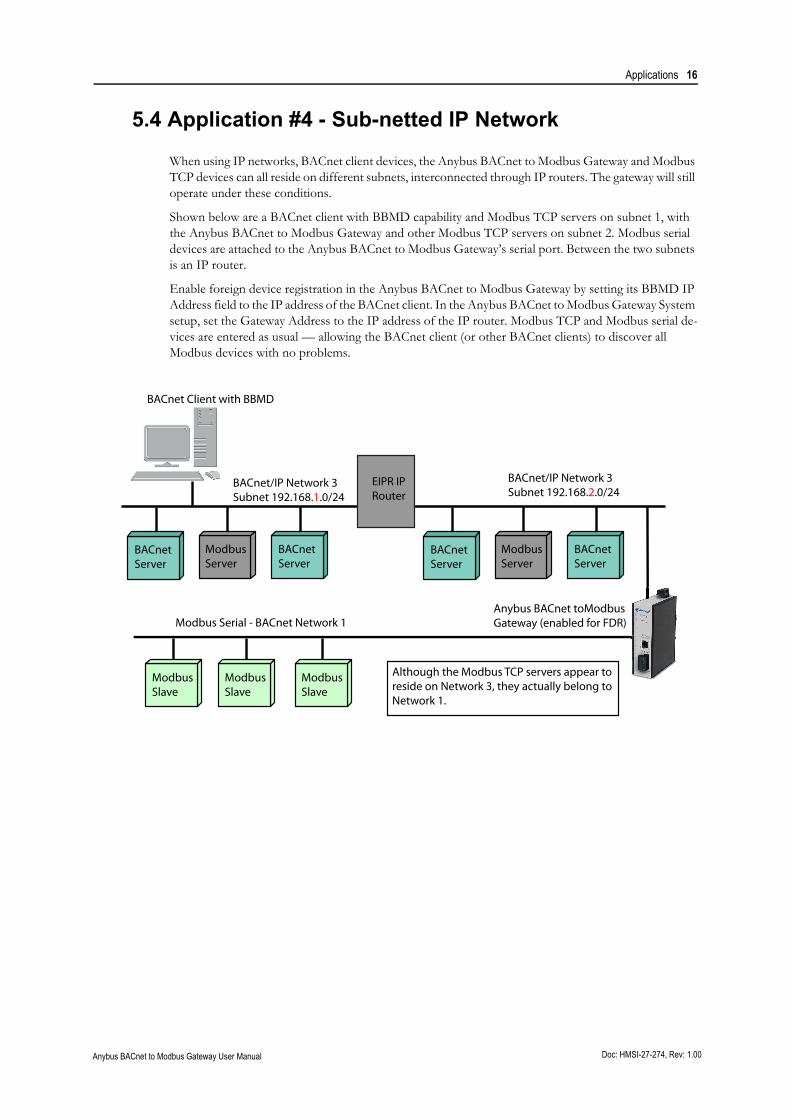
Shown below are a BACnet client with BBMD capability and Modbus TCP servers on subnet 1, with the Anybus BACnet to Modbus Gateway and other Modbus TCP servers on subnet 2. Modbus serial devices are attached to the Anybus BACnet to Modbus Gateway’s serial port. Between the two subnets is an IP router.
Enable foreign device registration in the Anybus BACnet to Modbus Gateway by setting its BBMD IP Address field to the IP address of the BACnet client. In the Anybus BACnet to Modbus Gateway System setup, set the Gateway Address to the IP address of the IP router. Modbus TCP and Modbus serial de-vices are entered as usual — allowing the BACnet client (or other BACnet clients) to discover all Modbus devices with no problems.
BACnet Client with BBMD
BACnet/IP Network 3Subnet 192.168.1.0/24
Modbus Serial - BACnet Network 1Anybus BACnet toModbus Gateway (enabled for FDR)
ModbusServer
BACnet/IP Network 3Subnet 192.168.2.0/24
Although the Modbus TCP servers appear to reside on Network 3, they actually belong to Network 1.
ModbusSlave
ModbusSlave
ModbusSlave
BACnetServer
BACnetServer
ModbusServer
BACnetServer
BACnetServer
EIPR IP Router

Anybus BACnet to Modbus Gateway User Manual Doc: HMSI-27-274, Rev: 1.00
Appendix A
A. Technical Specifications
Power Requirements: 24 VAC ±10% 10 VA 47–63 Hz, or 24 VDC ±10% 6W
Operating Temp: 0°C to +60°C
Storage Temp: -40°C to +85°C
Relative Humidity: 10–95%, non-condensing
Ingress Protection: IP30
Communication Ethernet RS-485
Compliance: IEEE 802.3 Modbus V1.02
Protocols supported: Modbus TCP RTU Master
BACnet/IP ASCII Master
Data rate: 10 Mbps, 100 Mbps 2.4, 4.8 9.6, 19.2, 38.4, 57.6, 115.2 kbps
Physical layer: 10BASE-T, 100BASE-TX RS-485, 3-wire isolated
Cable length (max) 100m 1200m (1000m if using 115.2 kbps)
Port connector: Shielded RJ-45 5-pin removable terminal
LEDs: L (Link) D (Duplex) Tx Rx
Green = 100 Mbps Green = Full-duplex Green= Activity Green = Activity
Yellow = 10 Mbps Off = Half-duplex
Flash = activity Flash = Collision
Regulatory Compliance: CE Mark; CFR 47
Part 15 Class A
RoHS
UL 508; C22.2 No. 142-M1987