Backhoe - Toro
20
Operator’s Manual Original Instructions (EN) Register your product at www.Toro.com. Form No. 3354-432 Rev A Backhoe for Compact Utility Loaders Model No. 23163—260000001 and Up
Transcript of Backhoe - Toro

Operator’s Manual
Original Instructions (EN)Register your product at www.Toro.com.
Form No. 3354-432 Rev A
Backhoefor Compact Utility LoadersModel No. 23163—260000001 and Up
2
Copyright 2006 by The Toro Company8111 Lyndale Avenue SouthBloomington, MN 55420-1196
Contact us at www.Toro.comAll Rights Reserved
Printed in the USA
ContentsPage
Introduction 2. . . . . . . . . . . . . . . . . . . . . . . . . . . . . . . . . Safety 2. . . . . . . . . . . . . . . . . . . . . . . . . . . . . . . . . . . . . .
Safety and Instruction Decals 3. . . . . . . . . . . . . . . . . Specifications 6. . . . . . . . . . . . . . . . . . . . . . . . . . . . . . . .
Stability Ratings 6. . . . . . . . . . . . . . . . . . . . . . . . . . . Setup 7. . . . . . . . . . . . . . . . . . . . . . . . . . . . . . . . . . . . . .
Loose Parts 7. . . . . . . . . . . . . . . . . . . . . . . . . . . . . . . Installing the Heat Shield 7. . . . . . . . . . . . . . . . . . . . Installing the 200/300 Series Traction Unit
Backhoe Kit 8. . . . . . . . . . . . . . . . . . . . . . . . . . . . . Installing the TX Series Traction Unit Backhoe Kit 9Greasing the Backhoe 10. . . . . . . . . . . . . . . . . . . . . . Adjusting the Seat 10. . . . . . . . . . . . . . . . . . . . . . . . .
Operation 10. . . . . . . . . . . . . . . . . . . . . . . . . . . . . . . . . . . Operation Checklist 10. . . . . . . . . . . . . . . . . . . . . . . . Backhoe Overview 11. . . . . . . . . . . . . . . . . . . . . . . . . Controls 11. . . . . . . . . . . . . . . . . . . . . . . . . . . . . . . . . Connecting the Backhoe to the Traction Unit 11. . . . Operating the Backhoe 12. . . . . . . . . . . . . . . . . . . . . . Securing the Backhoe for Transport 15. . . . . . . . . . . Disconnecting the Backhoe from
the Traction Unit 16. . . . . . . . . . . . . . . . . . . . . . . . . Maintenance 17. . . . . . . . . . . . . . . . . . . . . . . . . . . . . . . . .
Service Interval Chart 17. . . . . . . . . . . . . . . . . . . . . . Greasing and Lubrication 17. . . . . . . . . . . . . . . . . . . .
Storage 17. . . . . . . . . . . . . . . . . . . . . . . . . . . . . . . . . . . . . Troubleshooting 18. . . . . . . . . . . . . . . . . . . . . . . . . . . . . .
IntroductionRead this manual carefully to learn how to operate andmaintain your product properly. The information in thismanual can help you and others avoid injury and productdamage. Although Toro designs and produces safeproducts, you are responsible for operating the productproperly and safely.
You may contact Toro directly at www.Toro.com forproduct and accessory information, help finding a dealer, orto register your product.
Whenever you need service, genuine Toro parts, oradditional information, contact an Authorized ServiceDealer or Toro Customer Service and have the model andserial numbers of your product ready. You will find themodel and serial number on a plate located on the product.
Write the product model and serial numbers in the spacebelow:
Model No.
Serial No.
This manual identifies potential hazards and has specialsafety messages that help you and others avoid personalinjury and even death. Danger, Warning, and Caution aresignal words used to identify the level of hazard. However,regardless of the hazard, be extremely careful.
Danger signals an extreme hazard that will cause seriousinjury or death if you do not follow the recommendedprecautions.
Warning signals a hazard that may cause serious injury ordeath if you do not follow the recommended precautions.
Caution signals a hazard that may cause minor or moderateinjury if you do not follow the recommended precautions.
This manual uses two other words to highlight information.Important calls attention to special mechanical
information and Note: emphasizes general informationworthy of special attention.
SafetyImproper use or maintenance by the operator or ownercan result in injury. To reduce the potential for injury,comply with the safety instructions in the traction unitoperator’s manual and always pay attention to thesafety alert symbol, which means CAUTION,WARNING, or DANGER—“personal safetyinstruction.” Failure to comply with the instruction mayresult in personal injury or death.
Danger
There may be buried power, gas, and/or telephonelines in the work area. Electric shock, death, orexplosion may occur.
Have the property or work area marked for buriedlines and do not dig in marked areas.

3
Danger
There may be overhead power lines in the workarea. Electric shock or death may occur if a powerline is touched by the backhoe.
Survey and mark the area where there areoverhead power lines, and dig with caution underpower lines, to ensure that you do not touch themwith the backhoe.
When going up or down hill, the machine couldoverturn if the heavy end is toward the downhillside. Someone may be pinned or seriously injuredby the machine if it overturns.
Operate up and down slopes with the backhoeuphill.
Warning
The tires of the traction unit can be slippery. If thetires are used as a step to climb on to or off of thebackhoe, the operator could slip and fall, causinginjury.
Use the step provided when climbing on to or off ofthe backhoe and not the traction unit tires.
Caution
Safety and Instruction Decals
Safety decals and instructions are easily visible to the operator and are located near any areaof potential danger. Replace any decal that is damaged or lost.
100-41321. Crushing hazard, backhoe—keep bystanders a safe distance
from the backhoe.

4
100-41331. Warning—read the Operator’s Manual.2. Explosion and electric shock hazards—do not dig in areas with buried gas or electrical lines, and do not operate under overhead electrical
lines.3. Crushing hazard, backhoe—lock the boom before leaving the machine.4. Tipping hazard—do not move the traction unit while seated on the backhoe, install the counter–weight, and lower the stabilizers.
100-41341. Lock the boom before transporting the backhoe.
100-41351. Install and secure the side bars before operating the backhoe.
100-41361. Crushing hazard of hand and foot—keep hands and feet a safe
distance from a moving stabilizer.
100-41371. Tipping hazard—do not move the traction unit while seated on
the backhoe.

5
100-72631. Crushing hazard of hand—read the Operator’s Manual.
108-5665
108-56931. Lower the boom.2. Rotate the boom left.3. Rotate the boom right.
4. Raise the boom.5. Lower the left stabilizer.6. Lower the right stabilizer.
7. Raise the left stabilizer.8. Raise the right stabilizer.9. Raise the dipperstick.
10. Curl the bucket.11. Dump the bucket.12. Lower the dipperstick.

6
SpecificationsNote: Specifications and design are subject to change without notice.
Width 34.5 inches (87.6 cm)
Length 41 inches (104 cm)
Transport height 71 inches (180 cm)
Weight 762 lbs (346 Kg)
Digging depth (maximum) 82 inches (208 cm)
Bucket rotation 180 degrees
Swing arc 180 degrees
Stabilizer spread (working) 78 inches (198 cm)
Stability RatingsTo determine the degree of slope you can traverse with thebackhoe installed on a traction unit, find the stability ratingfor the hill position you want to travel in the followingtable, then find the degree of slope for the same rating andhill position in the Stability Data section of the traction unitoperator’s manual.
Exceeding the maximum recommended slope cancause the traction unit to tip, crushing you orbystanders.
Do not drive the traction unit on a slope steeperthan the maximum recommended slope, asdetermined in the following table and the tractionunit operator’s manual.
Warning
Orientation Stability Rating
Front Uphill
CRear Uphill
DSide Uphill
CImportant If your traction unit has a rear operator’s
platform, the counterweight must be used on the platformwhile using the backhoe, or the traction unit will becomeunstable.

7
SetupLoose PartsNote: Use the chart below to identify parts for assembly.
Description Qty. Use
Frame
Vinyl Cover
Bolts, 1/4 x 1-1/4 in.
1
1
2
Install the heat shield
Backhoe Kit for a 200/300 Series traction unit(sold separately)
Backhoe Kit for a TX Series traction unit (soldseparately)
1
1One kit required to connect the backhoe to yourtraction unit
The backhoe mounts slightly differently to the 200/300 series traction unit than it does to the TX. You must obtain and installthe Backhoe kit appropriate for your traction unit. Use the instructions provided in this section to install these kits.
Installing the Heat Shield1. Place the vinyl cover on the underside of the frame and
secure it around the rods with the hook and loopfasteners (Fig. 1).
m-6440
2
1
4
3
5
Figure 11. Vinyl cover2. Frame rods (not covered
by vinyl cover)3. Bolts and nuts (not
shown) at the rear of theplatform
4. Seat stand5. Operator platform
2. Remove the seat and the seat bracket from the seatstand.
3. Remove the 2 bolts and 2 nuts at the rear of the operatorplatform (Fig. 1). Discard the bolts but save the nuts forstep 5.
4. Place the heat shield down over the seat stand (Fig. 1).
5. Use the 2 bolts from the kit (1/4 x 1-1/4 in.) and the2 nuts (1/4 in.) that you removed in step 3 to secure thetabs at the base of the heat shield to the operatorplatform.
6. Install the seat.
8
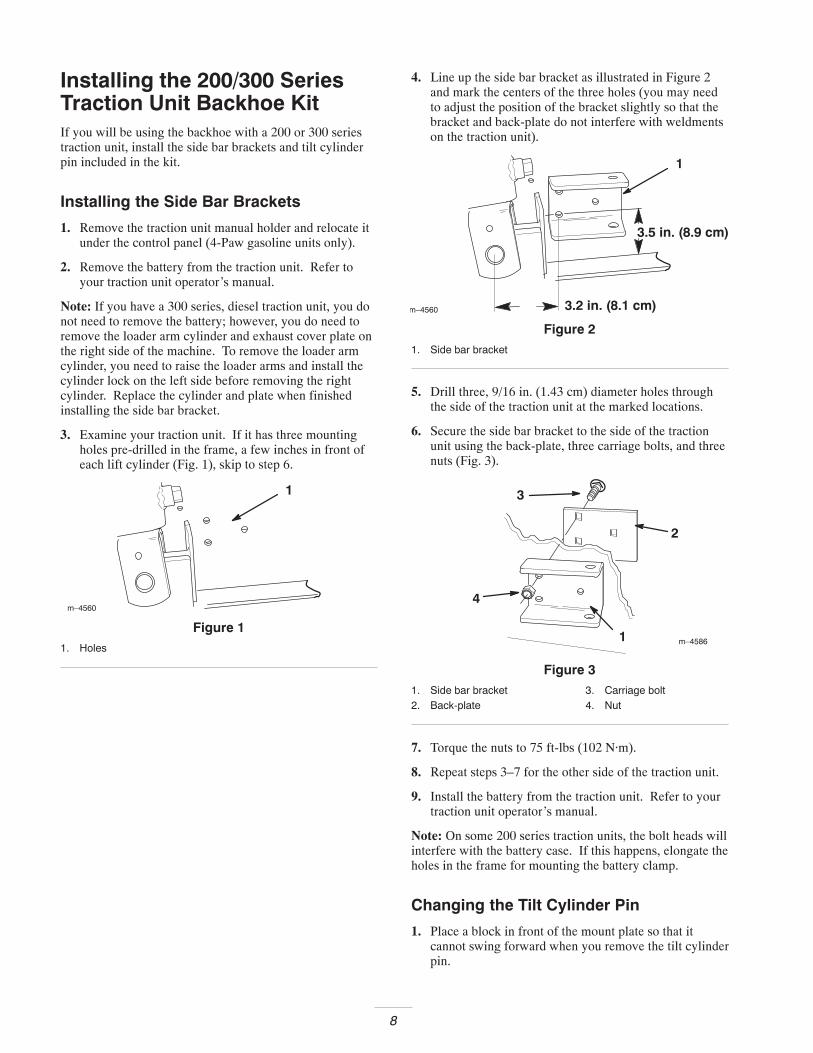
Installing the 200/300 SeriesTraction Unit Backhoe KitIf you will be using the backhoe with a 200 or 300 seriestraction unit, install the side bar brackets and tilt cylinderpin included in the kit.
Installing the Side Bar Brackets
1. Remove the traction unit manual holder and relocate itunder the control panel (4-Paw gasoline units only).
2. Remove the battery from the traction unit. Refer toyour traction unit operator’s manual.
Note: If you have a 300 series, diesel traction unit, you donot need to remove the battery; however, you do need toremove the loader arm cylinder and exhaust cover plate onthe right side of the machine. To remove the loader armcylinder, you need to raise the loader arms and install thecylinder lock on the left side before removing the rightcylinder. Replace the cylinder and plate when finishedinstalling the side bar bracket.
3. Examine your traction unit. If it has three mountingholes pre-drilled in the frame, a few inches in front ofeach lift cylinder (Fig. 1), skip to step 6.
m–4560
1
Figure 11. Holes
4. Line up the side bar bracket as illustrated in Figure 2and mark the centers of the three holes (you may needto adjust the position of the bracket slightly so that thebracket and back-plate do not interfere with weldmentson the traction unit).
m–4560
3.5 in. (8.9 cm)
1
3.2 in. (8.1 cm)
Figure 21. Side bar bracket
5. Drill three, 9/16 in. (1.43 cm) diameter holes throughthe side of the traction unit at the marked locations.
6. Secure the side bar bracket to the side of the tractionunit using the back-plate, three carriage bolts, and threenuts (Fig. 3).
m–4586
4
3
2
1
Figure 31. Side bar bracket2. Back-plate
3. Carriage bolt4. Nut
7. Torque the nuts to 75 ft-lbs (102 N·m).
8. Repeat steps 3–7 for the other side of the traction unit.
9. Install the battery from the traction unit. Refer to yourtraction unit operator’s manual.
Note: On some 200 series traction units, the bolt heads willinterfere with the battery case. If this happens, elongate theholes in the frame for mounting the battery clamp.
Changing the Tilt Cylinder Pin
1. Place a block in front of the mount plate so that itcannot swing forward when you remove the tilt cylinderpin.

9
When you remove the tilt cylinder pin, the mountplate may swing forward, crushing your feet orhands, or those of bystanders.
Block up the mount plate before removing the tiltcylinder pin.
Caution
2. Remove the bolt securing the upper tilt cylinder pin(Fig. 4).
3. Using a hammer and punch, remove the tilt cylinderpin.
m–4562
2
1
3
Figure 41. Tilt cylinder2. Tilt cylinder pin
3. Bolt
4. Apply a generous coating of grease to the new pin.
5. Install the new pin into position and secure it with a bolt(Fig. 5).
Note: Leave the new pin installed, even when you removethe backhoe.
m–4976
1
2
Figure 51. New tilt cylinder pin 2. Bolt
Installing the TX SeriesTraction Unit Backhoe KitIf you will be using the backhoe with a 400 series (TX)traction unit, install the tilt cylinder pin included in the kit.
1. Block up the mount plate so that it cannot swingforward.
When you remove the tilt cylinder pin, the mountplate may swing forward, crushing your feet orhands, or those of bystanders.
Block up the mount plate before removing the tiltcylinder pin.
Caution
2. Remove the bolt and nut securing the upper tilt cylinderpin on the traction unit (Fig. 6).
3. Using a hammer and punch, remove the tilt cylinderpin.
4. Install the new pin into position and secure it with thebolt and nut removed previously, using the middle holeon the pin (Fig. 6).
5. Grease the pin using the fitting on the tilt cylinder.
Note: Leave the new pin installed, even when the backhoeis removed.
m–4911
1
2
3
5
4
Figure 61. Tilt cylinder2. Bolt3. Nut
4. New tilt cylinder pin5. Middle hole
Greasing the BackhoeBefore using the backhoe for the first time, ensure that allof the fittings are fully greased; refer to Greasing andLubrication, page 17.

10
Adjusting the Seat
The seat mounting bracket has several pinchpoints. You could pinch and/or cut your fingerswhen adjusting the seat.
Take care to keep your fingers away from the seatmounting bracket when moving the seat up anddown and when lowering the seat into position.
Caution
1. Stop the engine.
2. Tilt the seat forward.
3. Loosen the knobs on the bottom of the seat (Fig. 7) andslide the seat forward or back as needed.
4. To adjust the seat height, remove the hairpin cotter andpin from the seat stand (Fig. 7) and raise or lower theseat as required.
m–45473
21
Figure 71. Seat2. Knobs
3. Pin and hairpin cotter
5. When you have the proper height, install the pin andhairpin cotter to secure the seat.
OperationNote: Always use the traction unit to lift and move theattachment.
Operation ChecklistTo ensure safe, effective use of the backhoe, complete thefollowing activities before, during, and after operating thebackhoe:
Note: For detailed descriptions of these procedures, refer toInstalling the Backhoe on the Traction Unit (page 11) andOperating the Backhoe (page 12).
Before Operation:
• Locate and mark underground utilities.
• Install the counterweight on the traction unit.
• Install the links between the backhoe and the tiltcylinder pin on the traction unit.
• Install the side bars between the backhoe and thetraction unit frame (200/300 series traction units only).
• Install the hydraulics lever clamp over the traction unitcontrols.
• Lower the stabilizer arms before digging.
During Operation:
Only operate the backhoe from the backhoe seat.
Only move the traction unit from the traction unitoperator’s position and not from the seat of the backhoe.
After Operation:
Install the pins securing the boom from moving up anddown and side to side (Figs. 16 and 17) before leaving thebackhoe unattended, transporting it, or disconnecting itfrom the traction unit.

11
Backhoe OverviewFigure 8 illustrates the backhoe. Familiarize yourself withall of the components listed in Figure 8.
m-?
1
23
4
5
6
Figure 81. Seat2. Controls3. Boom
4. Dipperstick5. Bucket6. Stabilizer
ControlsFamiliarize yourself with all of the controls listed in Figure9 before you operate the backhoe.
m-?
32
1
Figure 91. Stabilizer control levers2. Boom control lever
3. Dipperstick/bucket controllever
Note: On CE units the control for raising and lowering thedipperstick and raising and lowering the boom are reversed(i.e., the boom control is on the right and the dipperstickcontrol is on the left). The swing and bucket controls donot change.
Stabilizer Control Levers
Move the stabilizer control levers forward to lower thestabilizers and rearward to raise the stabilizers.
Boom Control Lever
Move the boom control lever forward to lower the boomand rearward to raise the boom. Move the boom controllever to the right to swing the boom to the right and move itleft to swing the boom to the left.
You can also move the boom control lever into anintermediate position (i.e., forward and left, forward andright, rearward and left, or rearward and right) to swing theboom at the same time as you raise or lower it.
Dipperstick/Bucket Control Lever
Move the dipperstick/bucket control lever forward toextend the dipperstick and rearward to retract thedipperstick. Move the dipperstick/bucket control lever tothe right to dump the bucket and move it left to load thebucket.
You can also move the dipperstick/bucket control lever intoan intermediate position (i.e., forward and left, forward andright, rearward and left, or rearward and right) to extend orretract the dipperstick at the same time as you load or dumpthe bucket.
Connecting the Backhoe to theTraction UnitImportant Before connecting any attachments to the
traction unit, ensure that the mount plates are free of anydirt or debris and that the pins rotate freely.
1. Start the engine.
2. Attach the backhoe to the traction unit mount plate asdescribed in the traction unit Operator’s Manual.
3. Tilt the backhoe part of the way back.
4. Stop the engine.
5. Attach the hydraulic hoses to the traction unit asdescribed in the traction unit Operator’s Manual.
6. Start the engine.
7. Tilt the backhoe all the way back.
Tilting the backhoe can pinch or crush your hands.
Keep away from the moving backhoe when tilting.
Caution

12
8. Slide the two links on each end of the tilt cylinder pinand the backhoe link pin and secure them with twolynch pins (Fig. 10 for 200/300 Series traction units orFig. 11 for TX traction units).
Note: You may need to move the attachment tilt lever toline up the holes in the links with the pins.
m–4130
12
3
4
4
Figure 101. Tilt cylinder pin2. Backhoe link pin
3. Link4. Lynch pin
m–4914
1 2
3
4
4
Figure 111. Tilt cylinder pin2. Backhoe link pin
3. Link4. Lynch pin
9. If you are installing the backhoe on a 200/300 seriestraction unit, install the side bars on each side asillustrated in Figure 12. The decal on each side barmust be visible when installed.
Important If the bars do not fit snuggly, remove them,loosen the jam nut, and thread the compound side bartogether or apart as needed to ensure that they fit as tight aspossible (Fig. 12). Tighten the jam nut when finished.
Note: If you have a 300 series, diesel traction unit, youmay need to loosen the hood and slide it up in the mountingslots to ensure that the hood does not interfere with the sidebars.
m–45611
3
24
Figure 121. Side bar2. Pin
3. Hairpin cotter4. Jam nut
Operating the BackhoePreparing the Backhoe
1. Drive to the work location.
2. If you are using the backhoe with a 200/300 seriestraction unit, install the auxiliary hydraulics clamp asfollows:
A. Set the speed selector lever to the slow (turtle)position and the throttle to the 2/3 full position.
B. Pull the auxiliary hydraulics lever to the operatorgrip and install the hydraulics lever clamp bypushing it over the hand grip and sliding it right sothat the pin through the clamp slides under the righthand grip (Fig. 13).
C. If your traction unit has a parking brake, engage it.
12
3
m–4641
Figure 131. Hydraulics lever clamp2. Pin
3. Auxiliary hydraulics lever

13
3. If you are using the backhoe with a TX traction unit,install the auxiliary hydraulics clamp as follows:
A. Set the throttle 2/3 of the way to the rabbit positionon the traction unit.
B. Pull the lever and clamp down to the reference barso that the clamp routes behind the loaderarm/attachment tilt lever.
1
m–4912
2
Figure 141. Hydraulics lever clamp 2. Auxiliary hydraulics lever
C. Set the parking brake and release the clamp so that itcatches under the brake lever (Fig. 15).
m–4913
Figure 151. Hydraulics lever clamp2. Pin
3. Auxiliary hydraulics lever
4. Push the stabilizer control levers forward to lower bothstabilizers until they touch the ground and the frontwheels of the traction unit come off of the groundslightly.
5. Remove the two pins locking the boom in place(Figs. 16 and 17) and place them in the storagepositions (Fig. 18).
Note: One pin prevents the boom from swinging side toside (Fig. 16) and the other prevents the boom from movingup and down (Fig. 17).
m-?
1
Figure 161. Pin
m-?
1
Figure 171. Pin
m-?
1
2
Figure 181. Pin 2. Lynch pin

14
Digging a Hole
Using a backhoe with precision and proficiency takes timeand practice. In general, you dig a hole by extending thedipperstick and bucket, lowering them into the ground, andthen pullback on the dipperstick while raising the boom andcurling the bucket rearward (Fig. 19).
A
B
C
m-?
Figure 19
To empty the bucket you swing it to the left or right andextend the dipperstick and uncurl bucket, dumping the load(Fig. 20).
m-?A B
Figure 20
The distance you extend the dipperstick and bucket and thesize of bite you take will vary greatly with the soil type,moisture content of the soil, and obstructions in the soil,such as tree roots and rocks.
Spend some time practicing with the backhoe to get the feelfor how it operates and how to best use it in the conditionsin which you work. Please read and use the following tipswhen operating the backhoe:
• Do not dig too close to the backhoe body or stabilizers.The backhoe could undercut the stabilizers or tractionunit causing the machine to fall into the hole.
If you dig too close to the backhoe, the backhoecould fall into the hole, tipping on top of youcausing severe injury.
Ensure that you do not dig within three feet of thebackhoe or stabilizers.
Warning
• Do not take large bites of soil. Instead, sweep thebucket through the soil using the swinging motion ofthe dipperstick a few inches deep at a time.
• If the bucket catches in the soil, uncurl the bucket, raisethe boom slightly, and continue digging.
• If your traction unit has a speed selector, set it to thefast position (rabbit) while you are learning how tooperate the backhoe (this will slow the backhoe down).Set it to the slow position (turtle) once you feel youhave mastered the use of the backhoe.
• If your traction unit has a flow divider, set it to the 11o’clock position.

15
Securing the Backhoe forTransport
If you do not secure the boom, it could swing orlower during transport or when disconnecting thebackhoe from the traction unit. The traction unitcould become unstable causing loss of control andyou or bystanders could be injured. If the boomswings when disconnecting, it could crush oramputate fingers or hands as you disconnect theattachment locking pins.
Always secure the boom before transport andbefore disconnecting the backhoe from the tractionunit.
Warning
1. Fully raise the boom, retract the dipperstick, and curlthe bucket rearward (Fig. 21). Ensure that you centerthe boom locking pin holes as much as possible.
m-?
Figure 21
2. Pull the stabilizer levers rearward until the stabilizersare fully raised.
3. Secure the boom using the two pins removed prior tooperation (Figs. 22 and 23).
m-?
1
Figure 221. Pin
m-?
1
Figure 231. Pin 2. Lynch pin
4. Stop the engine and remove the key.
5. Remove the hydraulics lever clamp (Fig. 13 or 14).
6. Secure the clamp to the backhoe by inserting the end ofthe pin through the clamp into the hole in the side of thecontrol tower (Fig. 24 for 200/300 series traction units.The TX traction unit has a shorter pin through itsclamp).
m-?
1
2
Figure 241. Pin 2. Clamp
7. Slowly transport the backhoe as needed.

16
Disconnecting the Backhoefrom the Traction Unit1. Secure the backhoe in the transport position (refer to
Securing for Transport, page 15), move the backhoe to alevel storage area, and stop the engine.
If you do not secure the boom, it could swing orlower during transport or when disconnecting thebackhoe from the traction unit. The traction unitcould become unstable causing loss of control andyou or bystanders could be injured. If the boomswings when disconnecting, it could crush oramputate fingers or hands as you disconnect theattachment locking pins.
Always secure the boom before transport andbefore disconnecting the backhoe from the tractionunit.
Warning
2. If you are removing the backhoe from a 200/300 Seriestraction unit, remove the side bars as follows:
A. Remove the hairpin cotters and pins securing theside bars and remove the side bars (Fig. 12).
B. Pin the side bars in the storage positions asillustrated in Figure 25.
m-?
Figure 25
3. Start the engine.
4. Remove the lynch pins securing the links and removethe links (Fig. 10 or 11).
Note: You may need to adjust the tilt lever slightly toloosen the links.
5. Secure the links and two lynch pins for storage on thepins on the backhoe and the other two lynch pins on thetraction unit tilt cylinder pin.
6. Disengage the attachment lock pins by turning them tothe outside.
7. Tilt the backhoe forward slowly until the storagesupports on the backhoe receiver plate and the bucketcontacts the ground.
If you remove the backhoe from the traction unitwithout a bucket installed on the dipperstick, thebackhoe will be unstable. The backhoe could tipover injuring you or other bystanders.
Do not remove the backhoe from the traction unitwithout first installing a bucket onto the backhoe.
Warning
8. Stop the engine.
9. Move the auxiliary hydraulic lever forward, backward,and back to the neutral position to relieve hydraulicpressure at the hydraulic couplers.
10. Slide the collar back on hydraulic couplers anddisconnect them.
11. Install protective covers onto the hydraulic couplers onthe traction unit.
12. Start the engine.
13. Tilt the mount plate forward and back the traction unitaway from the backhoe.

17
Maintenance
If you leave the key in the ignition switch, someonecould start the engine. Accidental starting of theengine could seriously injure you or otherbystanders.
Remove the key from the ignition switch beforeyou do any maintenance.
Caution
Service Interval Chart
ServiceOperation 8 Hrs 25 Hrs
StorageService
Grease fittings X X
Inspect for leaks X X
Chippedsurfaces–paint
X
Greasing and LubricationService Interval/Specification
Grease all fittings every 8 operating hours (Fig. 26). Notethat in most cases the grease fittings are located in thecenter of every pivot pin. Also, grease the fitting in theswing cylinder pivot pin, located under the seat column,under the backhoe (this location is not shown in Figure 26).
Grease all fittings immediately after every washing.
Grease Type: General-purpose grease
How to Grease
1. Stop the engine and remove the key.
2. Clean the grease fittings with a rag.
3. Connect a grease gun to each fitting.
4. Pump grease into the fittings until grease begins to oozeout of the bearings.
5. Wipe up any excess grease.
m-?
Figure 26
Storage1. Before long term storage wash the attachment with mild
detergent and water to remove dirt and grime.
2. Apply grease to all grease fittings.
3. Check and tighten all bolts, nuts, and screws. Repair orreplace any part that are damaged or worn.
4. Paint all scratched or bare metal surfaces. Paint isavailable from your Authorized Service Dealer.
5. Store the attachment in a clean, dry garage or storagearea. Cover it to protect it and keep it clean.

18
TroubleshootingProblem Possible Causes Corrective Action
Backhoe does not operate 1. Hydraulic coupler notcompletely connected
1. Check and tighten all couplers.
2. Auxiliary hydraulics valve onthe traction unit is not fullyengaged.
2. Engage the valve.
3. Transport pins were notremoved.
3. Remove the pins.
4. Hydraulic fluid level is low. 4. Fill the traction unit hydraulictank.
5. Damaged hydraulic coupler 5. Check couplers and replaceany that are defective.
6. Obstructed hydraulic hose 6. Find and remove theobstruction.
7. Pinched hydraulic hose 7. Replace the hose.
8. Auxiliary hydraulic valve on thetraction unit is not opening.
8. Repair the valve.
9. Hydraulic coupler notcompletely connected
9. Check and tighten all couplers.
10.Bent piston rod 10.Contact your Authorized ToroDealer.
Backhoe is operating slowly 1. Hydraulic oil is cold. 1. Allow the engine to warm theoil before operating.
2. Engine speed is too slow. 2. Increase the throttle speed ofthe traction unit.
3. Pinched hydraulic hose 3. Replace the hose.
4. Damaged cylinder 4. Contact your Authorized ToroDealer.
5. Damaged hydraulic pump 5. Contact your Authorized ToroDealer.
Backhoe fails to hold up a load (alll d ill ll ttl d
1. Damaged hydraulic hose 1. Replace the hose.p (loads will normally settle downover a long period of time) 2. Damaged cylinder 2. Contact your Authorized Toro
Dealer.
3. Damaged control valve 3. Contact your Authorized ToroDealer.
Hydraulic oil leakage 1. Damaged hydraulic hose 1. Replace the hose.y g
2. Damaged hydraulic system 2. Contact your Authorized ToroDealer.
Swing cylinder malfunctioning 1. Damaged cylinders, or swingrestrictors
1. Contact your Authorized ToroDealer.

19
Problem Corrective ActionPossible Causes
Control valve sticking or workingh d
1. Dirty hydraulic oil 1. Change the hydraulic oil.g ghard
2. Damaged or dirty valve 2. Contact your Authorized ToroDealer.
3. Damaged cylinder 3. Contact your Authorized ToroDealer.
Backhoe operation is spongy orjerky
1. Hydraulic fluid level is low. 1. Fill the traction unit hydraulictank.j y
2. Air in the hydraulic system 2. Extend the cylinders as far aspossible and hold them in anextended position for severalseconds.
3. Hydraulic oil is cold. 3. Allow the engine to warm theoil before operating.
4. Pinched hydraulic hose 4. Replace the hose.