BACKHOE NUAL - Oregon Tool
56
OPERATOR'S MANUAL BACKHOE (Rev. 10/22/2019) BH85 & BH100 MAN1272
Transcript of BACKHOE NUAL - Oregon Tool

OP
ER
AT
OR
'S M
AN
UA
LBACKHOE (R
ev. 1
0/22
/201
9)
BH85 & BH100M
AN12
72

2 Introduction Gen’l (Rev. 2/25/2016)
TO THE DEALER:Assembly and proper installation of this product is the responsibility of the Woods® dealer. Read manual instructionsand safety rules. Make sure all items on the Dealer’s Pre-Delivery and Delivery Check Lists in the Operator’s Manualare completed before releasing equipment to the owner.The dealer must complete the online Product Registration form at the Woods Dealer Website which certifies thatall Dealer Check List items have been completed. Dealers can register all Woods product atdealer.WoodsEquipment.com under Product Registration.Failure to register the product does not diminish customer’s warranty rights.
TO THE OWNER:Read this manual before operating your Woods equipment. The information presented will prepare you to do a better andsafer job. Keep this manual handy for ready reference. Require all operators to read this manual carefully and becomeacquainted with all adjustment and operating procedures before attempting to operate. Replacement manuals can beobtained from your dealer. To locate your nearest dealer, check the Dealer Locator at www.WoodsEquipment.com, or inthe United States and Canada call 1-800-319-6637.The equipment you have purchased has been carefully engineered and manufactured to provide dependable andsatisfactory use. Like all mechanical products, it will require cleaning and upkeep. Lubricate the unit as specified.Observe all safety information in this manual and safety decals on the equipment.For service, your authorized Woods dealer has trained mechanics, genuine Woods service parts, and the necessarytools and equipment to handle all your needs.Use only genuine Woods service parts. Substitute parts will void the warranty and may not meet standards required forsafe and satisfactory operation. Record the model number and serial number of your equipment in the spacesprovided:
Model: _______________________________ Date of Purchase: _____________________
Serial Number: (see Safety Decal section for location) ____________________________________Provide this information to your dealer to obtain correct repair parts.Throughout this manual, the term NOTICE is used to indicate that failure to observe can cause damage to equipment.The terms CAUTION, WARNING, and DANGER are used in conjunction with the Safety-Alert Symbol (a triangle withan exclamation mark) to indicate the degree of hazard for items of personal safety.

Introduction 3MAN1272 (10/22/2019)
TABLE OF CONTENTSINTRODUCTION . . . . . . . . . . . . . . . . . . . . . . . . . . . . . . . . . . . . . . . . . . . . . . . . . . . . . . . . . . . . . . . . . 2
SPECIFICATIONS . . . . . . . . . . . . . . . . . . . . . . . . . . . . . . . . . . . . . . . . . . . . . . . . . . . . . . . . 4GENERAL INFORMATION. . . . . . . . . . . . . . . . . . . . . . . . . . . . . . . . . . . . . . . . . . . . . . . . . . 6
SAFETY . . . . . . . . . . . . . . . . . . . . . . . . . . . . . . . . . . . . . . . . . . . . . . . . . . . . . . . . . . . . . . . . . . . . . . . 7SAFETY RULES. . . . . . . . . . . . . . . . . . . . . . . . . . . . . . . . . . . . . . . . . . . . . . . . . . . . . . . . . . 7
INSTALLATION . . . . . . . . . . . . . . . . . . . . . . . . . . . . . . . . . . . . . . . . . . . . . . . 7TRAINING . . . . . . . . . . . . . . . . . . . . . . . . . . . . . . . . . . . . . . . . . . . . . . . . . . . 7PREPARATION . . . . . . . . . . . . . . . . . . . . . . . . . . . . . . . . . . . . . . . . . . . . . . . 7OPERATION . . . . . . . . . . . . . . . . . . . . . . . . . . . . . . . . . . . . . . . . . . . . . . . . . 8TRANSPORTATION . . . . . . . . . . . . . . . . . . . . . . . . . . . . . . . . . . . . . . . . . . . 9MAINTENANCE. . . . . . . . . . . . . . . . . . . . . . . . . . . . . . . . . . . . . . . . . . . . . . . 9STORAGE . . . . . . . . . . . . . . . . . . . . . . . . . . . . . . . . . . . . . . . . . . . . . . . . . . 10
SAFETY & INSTRUCTIONAL DECALS . . . . . . . . . . . . . . . . . . . . . . . . . . . . . . . . . . . . . . . 11OPERATION . . . . . . . . . . . . . . . . . . . . . . . . . . . . . . . . . . . . . . . . . . . . . . . . . . . . . . . . . . . . . . . . . . . 13
OPERATION. . . . . . . . . . . . . . . . . . . . . . . . . . . . . . . . . . . . . . . . . . . . . . . . . . . . . . . . . . . . 13PTO HYDRAULIC PUMP (OPTIONAL). . . . . . . . . . . . . . . . . . . . . . . . . . . . 14GENERAL OPERATION . . . . . . . . . . . . . . . . . . . . . . . . . . . . . . . . . . . . . . . 14POSITION THE MACHINE . . . . . . . . . . . . . . . . . . . . . . . . . . . . . . . . . . . . . 14CONTROL HANDLE OPERATION . . . . . . . . . . . . . . . . . . . . . . . . . . . . . . . 14EXCAVATION . . . . . . . . . . . . . . . . . . . . . . . . . . . . . . . . . . . . . . . . . . . . . . . 15THUMB OPERATION . . . . . . . . . . . . . . . . . . . . . . . . . . . . . . . . . . . . . . . . . 17HYDRAULIC THUMB OPERATION . . . . . . . . . . . . . . . . . . . . . . . . . . . . . . 17TRANSPORTATION . . . . . . . . . . . . . . . . . . . . . . . . . . . . . . . . . . . . . . . . . . 18BACKHOE REMOVAL & STORAGE . . . . . . . . . . . . . . . . . . . . . . . . . . . . . . 19PRE-OPERATION CHECKLIST . . . . . . . . . . . . . . . . . . . . . . . . . . . . . . . . . 20
OWNER SERVICE . . . . . . . . . . . . . . . . . . . . . . . . . . . . . . . . . . . . . . . . . . . . . . . . . . . . . . . . . . . . . . 21OWNER SERVICE . . . . . . . . . . . . . . . . . . . . . . . . . . . . . . . . . . . . . . . . . . . . . . . . . . . . . . . 21
HYDRAULIC HOSES AND FITTINGS. . . . . . . . . . . . . . . . . . . . . . . . . . . . . 21RELIEF VALVE . . . . . . . . . . . . . . . . . . . . . . . . . . . . . . . . . . . . . . . . . . . . . . 21LUBRICATION. . . . . . . . . . . . . . . . . . . . . . . . . . . . . . . . . . . . . . . . . . . . . . . 21CLEANING . . . . . . . . . . . . . . . . . . . . . . . . . . . . . . . . . . . . . . . . . . . . . . . . . 22DISPOSAL. . . . . . . . . . . . . . . . . . . . . . . . . . . . . . . . . . . . . . . . . . . . . . . . . . 22LUBRICATION & MAINTENANCE SCHEDULE . . . . . . . . . . . . . . . . . . . . . 23TROUBLESHOOTING. . . . . . . . . . . . . . . . . . . . . . . . . . . . . . . . . . . . . . . . . 24
DEALER SERVICE . . . . . . . . . . . . . . . . . . . . . . . . . . . . . . . . . . . . . . . . . . . . . . . . . . . . . . . . . . . . . . 25DEALER SERVICE . . . . . . . . . . . . . . . . . . . . . . . . . . . . . . . . . . . . . . . . . . . . . . . . . . . . . . 25
HYDRAULIC VALVE REPAIR . . . . . . . . . . . . . . . . . . . . . . . . . . . . . . . . . . . 25ADJUST CONTROL VALVE LINKAGE . . . . . . . . . . . . . . . . . . . . . . . . . . . . 26HYDRAULIC CYLINDER REPAIR. . . . . . . . . . . . . . . . . . . . . . . . . . . . . . . . 27
ASSEMBLY . . . . . . . . . . . . . . . . . . . . . . . . . . . . . . . . . . . . . . . . . . . . . . . . . . . . . . . . . . . . . . . . . . . . 29ASSEMBLY . . . . . . . . . . . . . . . . . . . . . . . . . . . . . . . . . . . . . . . . . . . . . . . . . . . . . . . . . . . . 29
GENERAL ASSEMBLY INSTRUCTIONS . . . . . . . . . . . . . . . . . . . . . . . . . . 29HYDRAULIC INSTALLATION . . . . . . . . . . . . . . . . . . . . . . . . . . . . . . . . . . . 30OPTIONAL EQUIPMENT . . . . . . . . . . . . . . . . . . . . . . . . . . . . . . . . . . . . . . 31
DEALER CHECK LISTS . . . . . . . . . . . . . . . . . . . . . . . . . . . . . . . . . . . . . . . . . . . . . . . . . . . . . . . . . . 33PARTS INDEX. . . . . . . . . . . . . . . . . . . . . . . . . . . . . . . . . . . . . . . . . . . . . . . . . . . . . . . . . . . . . . . . . . 35APPENDIX . . . . . . . . . . . . . . . . . . . . . . . . . . . . . . . . . . . . . . . . . . . . . . . . . . . . . . . . . . . . . . . . . . . . 52
BOLT TORQUE CHART. . . . . . . . . . . . . . . . . . . . . . . . . . . . . . . . . . . . . . . . . . . . . . . . . . . 52BOLT SIZE CHART & ABBREVIATIONS . . . . . . . . . . . . . . . . . . . . . . . . . . . . . . . . . . . . . . 53
INDEX . . . . . . . . . . . . . . . . . . . . . . . . . . . . . . . . . . . . . . . . . . . . . . . . . . . . . . . . . . . . . . . . . . . . . . . . 54REPAIR PARTS WARRANTY. . . . . . . . . . . . . . . . . . . . . . . . . . . . . . . . . . . . . . . . . . . . . . . . . . . . . . 55PRODUCT WARRANTY . . . . . . . . . . . . . . . . . . . . . . . . . . . . . . . . . . . . . . . . . . . . . . . . . . . . . . . . . . 56
Si no lee Ingles, pida ayuda a alguien que si lo lee para que le
traduzca las medidas de seguridad.
LEA EL INSTRUCTIVO!!

4 Introduction MAN1272 (10/22/2019)
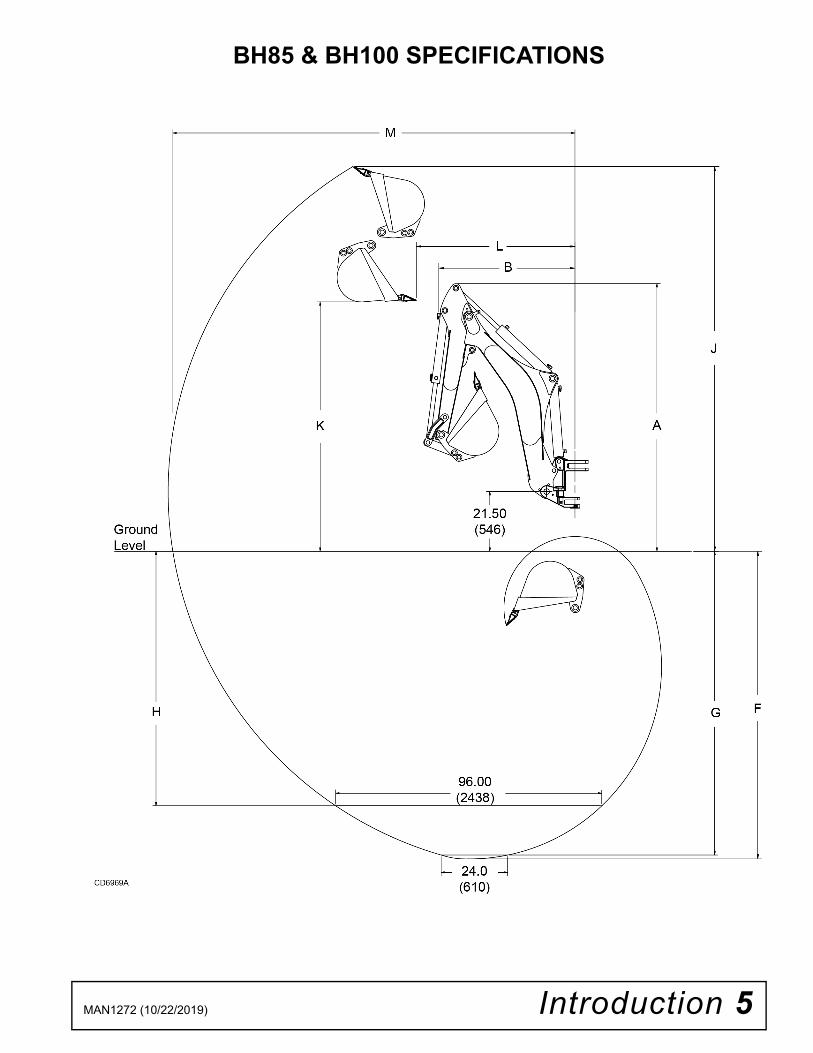
BH85 & BH100 SPECIFICATIONS
English MetricDescription Illustration BH85 BH100 BH85 BH100
Tractor PTO HP 30 - 100 HP 40 - 100 HP 22 - 75 kw 30 - 75 kwDigging Depth - Maximum F 103 in. 121 in. 2616 mm 3073 mmDigging Depth - 2’ Flat G 102 in. 120 in. 2591 mm 3048 mmDigging Depth - 8’ Flat H 82 in. 102 in. 2083 mm 2591 mmReach from Swing Pivot M 141 in. 161 in. 3581 mm 4089 mmLoading Height K 83 in. 100 in. 2108 mm 2540 mmLoading Reach L 61 in. 70 in. 1549 mm 1778 mmTransport Height A 94 in. 104 in. 2388 mm 2642 mmTransport Length B 55 in. 55 in. 1397 mm 1397 mmSwing Arc 180° 180° 180° 180°Bucket Rotation 180° 180° 180° 180°Stabilizer Spread - Up 76 in. 76 in. 1930 mm 1930 mmStabilizer Spread - Down 102 in. 102 in. 2591 mm 2591 mmLeveling Angle* 10° 10° 10° 10°Relief Pressure 2465 psi 2465 psi 17 Mpa 17 MpaBucket Digging Force 4600 lbs 4600 lbs 20462 N 20462 NDipperstick Digging Force 2940 lbs 2720 lbs 13078 N 12099 N
Bucket Capacity (Heaped) cu.-ft. cu.-meter12" (305 mm) 1.37 0.03915" (381 mm) 1.84 0.05218" (457 mm) 2.32 0.06624" (610 mm) 3.27 0.09336" (914 mm) 3.17 0.090
Per Definitions in Standards - SAE J49 and SAE J1234* Depends on Tractor Model and Tire Sizes
Introduction 5MAN1272 (10/22/2019)
BH85 & BH100 SPECIFICATIONS

6 Introduction MAN1272 (10/22/2019)
GENERAL INFORMATION
■ Some illustrations in this manual show thebackhoe with safety shields removed to provide abetter view. The backhoe should never be operatedwith any safety shielding removed.
The purpose of this manual is to assist in setting up,operating and maintaining your backhoe. Read it care-fully. It furnishes information and instructions that willhelp you achieve years of dependable performance.
These instructions have been compiled from extensivefield experience and engineering data. Some informa-tion may be general in nature due to unknown andvarying conditions. However, through experience andthese instructions, you should be able to develop pro-cedures suitable to your particular situation.
The illustrations and data used in this manual were cur-rent at the time of printing, but due to possible in-lineproduction changes, your machine may vary slightly indetail. We reserve the right to redesign and change themachines as may be necessary without notification.
Figure 1. Backhoe Directions
Throughout this manual, references are made to right,left, forward and rearward directions. These are deter-mined from the backhoe operator seat position facingthe backhoe as shown in Figure 1.
Terms for backhoe components have some variationsthroughout the industry. We use SAE designations asshown in Figure 2.
Figure 2. Backhoe Components
�������
1. Bucket2. Bucket cylinder3. Dipper stick4. Dipper cylinder5. Boom cylinder6. Boom7. Swing frame8. Swing cylinder9. Main frame
10. Console11. Stabilizer cylinder12. Stabilizer13. Stabilizer pad

Safety 7BH90-X_SR (Rev. 7/14/2006)
INSTALLATION Hydraulics must be connected as instructed inthis manual. Do not substitute parts, modify, orconnect in any other way.
After connecting hoses, check that all controllever positions function as instructed in the Opera-tor's Manual. Do not put into service until controllever and equipment movements are correct.
TRAINING
Safety instructions are important! Read allattachment and power unit manuals; follow allsafety rules and safety decal information. (Replace-ment manuals and safety decals are available fromyour dealer. To locate your nearest dealer, checkthe Dealer Locator at www.WoodsEquipment.com,or in the United States and Canada call 1-800-319-6637.) Failure to follow instructions or safety rulescan result in serious injury or death.
If you do not understand any part of this manualand need assistance, see your dealer.
Operators must be instructed in and be capableof the safe operation of the equipment, its attach-ments, and all controls. Do not allow anyone tooperate this equipment without proper instructions.
Know your controls and how to stop engine andattachment quickly in an emergency.
Keep hands and body away from pressurizedlines. Use paper or cardboard, not hands or otherbody parts to check for leaks. Wear safety goggles.Hydraulic fluid under pressure can easily penetrateskin and will cause serious injury or death.
PREPARATION Check that all hardware is properly installed.Always tighten to torque chart specificationsunless instructed otherwise in this manual.
Air in hydraulic systems can cause erratic oper-ation and allows loads or equipment componentsto drop unexpectedly. When connecting equipmentor hoses or performing any hydraulic maintenance,purge any air in hydraulic system by operating allhydraulic functions several times. Do this beforeputt ing into service or al lowing anyone toapproach the equipment.
After connecting hoses, check that all controllever positions function as instructed in the Opera-tor's Manual. Do not put into service until controllever and equipment movements are correct.
Protective hose sleeves must cover all hydrau-lic hoses within 40 inches of the operator and besecured onto metal hose fittings. Replace hoses orsleeves if damaged or if protective sleeve cannotbe properly positioned or secured.
Make sure all hydraulic hoses, fittings, andvalves are in good condition and not leaking beforestarting power unit or using equipment. Check androute hoses carefully to prevent damage. Hosesmust not be twisted, bent sharply, kinked, frayed,pinched, or come into contact with any movingparts. Operate moveable components through fulloperational range to check clearances. Replaceany damaged hoses immediately.
Make sure that all operating and service person-nel know that if hydraulic fluid penetrates skin, itmust be surgically removed as soon as possible bya doctor familiar with this form of injury or gan-grene, serious injury, or death will result. CON-TACT A PHYSICIAN IMMEDIATELY IF FLUIDENTERS SKIN OR EYES. DO NOT DELAY.
Always wear relatively tight and belted clothingto avoid getting caught in moving parts. Wearsturdy, rough-soled work shoes and protectiveequipment for eyes, hair, hands, hearing, and head;and respirator or filter mask where appropriate.
Make sure spring-activated locking pin or collarslides freely and is seated firmly in tractor PTOspline groove.
Make sure attachment is properly secured,adjusted, and in good operating condition.
(Safety Rules continued on next page)
Safety is a primary concern in the design andmanufacture of our products. Unfortunately, ourefforts to provide safe equipment can be wipedout by an operator’s single careless act.In addition to the design and configuration ofequipment, hazard control and accident preven-tion are dependent upon the awareness, con-cern, prudence, and proper training of personnelinvolved in the operation, transport, mainte-nance, and storage of equipment.It has been said, “The best safety device is aninformed, careful operator.” We ask you to bethat kind of operator.
SAFETY RULESATTENTION! BECOME ALERT! YOUR SAFETY IS INVOLVED!

8 Safety BH90-X_SR (Rev. 7/14/2006)
(Safety Rules continued from previous page) Connect PTO driveline directly to power unitPTO shaft. Never use adapter sleeves or adaptershafts. Adapters can cause driveline failures due toincorrect spline or incorrect operating length andcan result in personal injury or death. Power unit must be equipped with Roll OverProtection System (ROPS) or ROPS cab and seatbelt. Keep seat belt securely fastened. Falling offpower unit can result in death from being run overor crushed. Keep foldable ROPS system in “lockedup” position at all times. Only mount this backhoe on Category 1, 2, or 3Ntractors under 100 hp with 1800 lb. lift capacity at24” behind 3-point lift arm hitch balls. Never put backhoe into service unless backhoemanufacturer's 3-point hitch Saf-T-Lok® limiter orsub-frame has been installed and adjusted. To avoid possible hitch failure, read and followthe Saf-T-Lok Limiter Installation Instructions in theAssembly section before mounting backhoe totractor 3-point hitch. Do not use with 3-point quick attaching coupler. Do not use on tractor front 3-point hitch. Remove seat and upper support assemblybefore installing or removing backhoe from tractor.Failure to comply may result in equipment failureand/or personal injury. Do not operate backhoe unless there is ade-quate operator clearance as shown on safetydecal. (Refer to Danger decal in Safety Decal sec-tion.) Always use the special heavy-duty top link (pro-vided with backhoe) and the OEM high-strength toplink pin (provided with tractor) to mount the top linkto tractor. Be sure that backhoe is properly mounted,adjusted, and in good operating condition. Place and keep 3-point lift quadrant lever in low-ered position at all times. If tractor is equipped with draft sensing control,set control to “HEAVY” (minimum sensitivity) posi-tion. Make sure all safety decals are installed.Replace if damaged. (See Safety Decals section forlocation.) Make sure shields and guards are properlyinstalled and in good condition. Replace if damaged.
A minimum 25% of tractor and equipment weight must be on tractor front wheels when attachments are in transport position. Without this weight, front tractor wheels could raise up resulting in loss of steering. The weight may be attained with front wheel weights, ballast in tires, front tractor weights or front loader.Weigh the tractor and equipment as shown in Figure 3. The weight on the front tires, divided by the total weight on both front, plus rear tires, must be at least 25%. Do not install backhoe and required counter-weights on tractor if the total tractor and equipmentweight then exceeds the ROPS weight certificationof the tractor. To reduce overall weight of unit,remove liquid from rear tires and remove mid-mount mower, if equipped. Clean all dirt, trash, and grease from operator'splatform and steps.
Figure 3.Backhoe Stability Calculation
OPERATION Never allow children or untrained persons tooperate equipment. Do not allow bystanders within 25 feet of thearea when operating, attaching, removing, assem-bling, maintaining, or servicing equipment. Before operating, make sure stabilizer pads arelowered firmly to the ground. Stabilizer arms pro-vide support for the backhoe and support for thebackhoe mounting brackets. Consult local utilities before working. Knowlocation of all underground cables, pipelines, over-head wires, and other hazards in working area andavoid contact. Prevent trench cave-in by shoring, sloping, orstepping the sides of the trench.
SAFETY RULESATTENTION! BECOME ALERT! YOUR SAFETY IS INVOLVED!

Safety 9BH90-X_SR (Rev. 7/14/2006)
Keep materials & equipment a minimum of 2 ft.from the edge of excavation. Never enter a trench over 4 feet deep withoutprotective shoring and a way to climb out. Provide barricades to prevent people from fall-ing into trench. Keep bystanders away from operator, stabilizer,and maximum bucket swing areas. Do not operate or transport equipment whileunder the influence of alcohol or drugs. Operate only in daylight or good artificial light. Always comply with all state and local lightingand marking requirements. Do not allow riders. Do not lift or carry anybodyon the power unit or attachments. Power unit must be equipped with Roll OverProtection System (ROPS) or ROPS cab and seatbelt. Keep seat belt securely fastened. Falling offpower unit can result in death from being run overor crushed. Keep foldable ROPS system in “lockedup” position at all times. When operating controls, always sit in backhoeseat. The only time the backhoe may be operatedfrom a position other than the operator seat isduring backhoe attachment and removal. Operatormust:
• Read Mounting Kit Manual instructions onattaching and removing backhoe and useextreme care.• Always stand between rear tire and backhoestabilizer arms or along side of tractor to avoidbeing trapped should the boom swing controlbe accidentally activated.
Operate tractor PTO at 540 RPM. Do not exceed.
Always dump spoil at least two feet away fromopening.
Use extreme care when working close to fences,ditches, other obstructions, or on hillsides.
Be careful when swinging loaded bucket on ahillside. Always dump spoil on uphill side of back-hoe to minimize the possibility of upset.
Never leave equipment unattended with enginerunning or with bucket in raised position. Alwaysengage swing, stabilizer and boom transport locks,Relieve system pressure by operating controls,and remove ignition key before leaving equipment.
Do not use backhoe for craning; it is primarilydesigned for digging. Mechanical failures such ashose rupture will cause a load to drop suddenly.
TRANSPORTATION Always engage swing, stabilizer and boomtransport locks and attach Slow Moving Vehicle(SMV) sign before transporting backhoe. Power unit must be equipped with Roll OverProtection System (ROPS) or ROPS cab and seatbelt. Keep seat belt securely fastened. Falling offpower unit can result in death from being run overor crushed. Keep foldable ROPS system in “lockedup” position at all times. Never exceed 20 mph (32.2 km/h) during trans-port. Always comply with all state and local lightingand marking requirements. Never allow riders on power unit or attachment. Do not operate PTO during transport. Do not drive tractor with material in backhoebucket. Do not operate or transport on steep slopes.
Do not operate or transport equipment whileunder the influence of alcohol or drugs.
MAINTENANCE Do not modify or alter or permit anyone else tomodify or alter the equipment or any of its compo-nents in any way.
Do not allow bystanders within 25 feet of thearea when operating, attaching, removing, assem-bling, maintaining, or servicing equipment.
Your dealer can supply original equipmenthydraulic accessories and repair parts. Substituteparts may not meet original equipment specifica-tions and may be dangerous.
Adjustment of system relief pressure must bedone by a qualified, experienced dealership. Incor-rect adjustment can result in system failures andserious personal injury.
Always wear relatively tight and belted clothingto avoid getting caught in moving parts. Wearsturdy, rough-soled work shoes and protectiveequipment for eyes, hair, hands, hearing, and head;and respirator or filter mask where appropriate.
Dealer service personnel must perform workthat requires engine operation during service.
SAFETY RULESATTENTION! BECOME ALERT! YOUR SAFETY IS INVOLVED!

10 Safety BH90-X_SR (Rev. 7/14/2006)
Before working on backhoe, extend boom anddipperstick and place bucket on ground. Shut off thetractor engine. Make sure that all system pressurehas been relieved by operating controls before per-forming maintenance or service or before discon-necting any hydraulic lines.
Keep all persons away from operator controlarea while performing adjustments, service, ormaintenance.
Tighten all bolts, nuts, and screws to torquechart specifications. Check that all cotter pins areinstalled securely to ensure equipment is in a safecondition before putting unit into service.
Make sure all safety decals are installed.Replace if damaged. (See Safety Decals section forlocation.) Make sure shields and guards are properlyinstalled and in good condition. Replace if damaged.
STORAGE Block equipment securely for storage. Keep children and bystanders away from stor-age area. Refer to Removing and Storing Backhoe inOperation section of backhoe manual.
SAFETY RULESATTENTION! BECOME ALERT! YOUR SAFETY IS INVOLVED!

Safety 11MAN1272 (10/22/2019)
7 - PN 1020002 5 - PN 1020001
11 - PN W3788410 - PN W37885
BE CAREFUL!Keep safety decals clean and visible.Use a clean, damp cloth to clean safety decals.Avoid spraying too close to decals when using a pressure washer; high-pressure water can enter through very small scratches or under edges of decals causing them to peel or come off.
Replace safety decals if they are missing or illegible.Replacement safety decals can be ordered free from your Woods dealer. To locate your nearest dealer, check the Dealer Locator at www.WoodsEquipment.com, or in the United States and Canada call 1-800-319-6637.
1 - SERIAL NUMBER PLATE
(TRANSPORT LOCK) (TRANSPORT LOCK)
8 - PN 33437TRANSPORT LOCK
SAFETY & INSTRUCTIONAL DECALSATTENTION! BECOME ALERT! YOUR SAFETY IS INVOLVED!
Replace Immediately If Damaged!

12 Safety MAN1272 (10/22/2019)
SAFETY & INSTRUCTIONAL DECALSATTENTION! BECOME ALERT! YOUR SAFETY IS INVOLVED!
Replace Immediately If Damaged!
4 - PN 1008365
6 - PN 618130
2 - PN 618131
12 - PN 1032572
3 - PN 618133
13 - PN 606323
9 - PN 61813214 - PN 20106 (RED REFLECTOR)
15 - PN 18868

Operation 13MAN1272 (10/22/2019)
OPERATIONThe operator is responsible for the safe operation ofthe backhoe within its intended uses. The backhoe isintended for digging trenches, wider holes, moving soil,gravel, rocks, or stumps into a pile, or container andbackfilling. The accessory thumb is intended to pick upand move items that do not fit in the bucket. The opera-tor must be properly trained. Operators should befamiliar with the backhoe, the tractor and all safetypractices before starting operation. Read the SafetyRules and Safety Decals on pages 7 to 12.
■ Never operate without 3-point hitch Saf-T-Lok® kit or sub-frame kit. ■ Operator’s area (shaded area of 40” radius)must be free from all obstructions. ■ Use heavy-duty top link provided in 3 pointhitch Saf-T-Lok ® kit or sub-frame kit.■ Only use tractor manufacturer’s high strengthtop link pin of at least ¾” diameter and klik pinretainer. See 3 point mounting or sub-frame kit forinstallation instructions.■ Failure to follow the above instructions mayresult in serious injury or death from backhoebeing thrust upward, forward, or rearward by dig-ging forces.
Figure 3
Figure 4. Minimum Clearance Radius
Make sure all hydraulic hoses, fittings, andvalves are in good condition and not leaking beforestarting power unit or using equipment. Check androute hoses carefully to prevent damage. Hosesmust not be twisted, bent sharply, kinked, frayed,pinched, or come into contact with any movingparts. Operate moveable components through fulloperational range to check clearances. Replaceany damaged hoses immediately.
Keep hands and body away from pressurizedlines. Use paper or cardboard, not hands or otherbody parts to check for leaks. Wear safety goggles.Hydraulic fluid under pressure can easily penetrateskin and will cause serious injury or death.
Make sure that all operating and service person-nel know that if hydraulic fluid penetrates skin, it
must be surgically removed as soon as possible bya doctor familiar with this form of injury or gan-grene, serious injury, or death will result.
CONTACT A PHYSICIAN IMMEDIATELY IF FLUIDENTERS SKIN OR EYES. DO NOT DELAY.
A minimum 25% of tractor and equipmentweight must be on tractor front wheels with back-hoe in transport position. Without this weight, trac-tor could tip over, causing personal injury or death.The weight may be attained with a loader, frontwheel weights, ballast in tires, or front tractorweights. When attaining the minimum 25% weighton the front wheels, you must not exceed the RollOver Protection Structure (ROPS) weight certifica-tion. Weigh the tractor and equipment. Do not esti-mate.
Never allow children or untrained persons tooperate equipment.
������
�������

14 Operation MAN1272 (10/22/2019)
PTO HYDRAULIC PUMP (OPTIONAL)
■ Instructions for engaging and disengaging thePTO are in your tractor manual. Learn how to dis-engage PTO quickly should an emergency occur. Operate tractor PTO at 540 RPM. Do not exceed.An optional tractor-driven PTO pump is available. Thetractor-driven PTO pump supplies hydraulic pressurefor backhoe operation.When engaging hydraulic PTO mounted pump, engineRPM should always be low. Once engaged, engineRPM may be increased to desirable operation speed.IMPORTANT: Never exceed 540 RPM. Operating thepump in excess of 540 RPM will cause overheatingand equipment damage.
GENERAL OPERATION
Place and keep 3-point lift quadrant lever in low-ered position at all times. If tractor is equipped with draft sensing control,set control to “HEAVY” (minimum sensitivity) posi-tion. Do not use backhoe for craning; it is primarilydesigned for digging. Mechanical failures such ashose rupture will cause a load to drop suddenly. Never allow children or untrained persons tooperate equipment. Do not drive tractor with material in backhoebucket.
POSITION THE MACHINE
■ Place and keep 3-point lift quadrant lever inlowered position at all times.■ If tractor is equipped with draft sensing control,set to "HEAVY" (minimum sensitivity) position.■ Do not dig with backhoe unless stabilizers aredown on firm surface.Before operating in an unfamiliar area, walk around thefull length of the proposed site and check for hiddenholes, drop-off or obstacles that could cause an acci-dent.Disengage transport lock pin and swing lock pin. Placepins in storage position and secure with lock pins pro-vided (see Transportation section for storage location).
Lower stabilizers until they carry the weight of the back-hoe (see Control Handle Operation section forinstructions on operation of stabilizer controls). If trac-tor is equipped with a front loader, place the bucket flaton the ground. Lower loader lift arms until weight isremoved from front tractor tires. Level the machine using stabilizers and front loaderbefore starting to dig. Stability is very important when operating backhoe inthe extreme swing positions as this causes weighttransfer.
CONTROL HANDLE OPERATION
■ When operating controls, always sit in backhoeseat.It is not difficult to become a successful operator. Yourbackhoe is equipped with control lever operatingdecals on both the left and right side of your operator’sconsole as seen in Figure 5. Study these decals; theywill assist you in becoming familiar with the controls. When becoming familiar with backhoe controls, startwith a lower tractor engine RPM. Before operating, perform a functional test by placingthe control handles in their various positions and mak-ing certain correct operation occurs, matching decalson operator’s console. Pay specific attention to floatposition of boom. See Boom and Swing ControlssectionWARNING! Do not operate backhoe if control functionsdiffer from control decals; serious injury or death couldoccur.
STABILIZER CONTROLSPushing handle 1 forward will lower left stabilizer; pull-ing back raises it. Pushing handle 4 forward will lower right stabilizer;pulling back raises it. BOOM AND SWING CONTROLS (Handle 2, Figure 5)Pulling the handle back (towards A) raises boom;pushing it forward (toward C) lowers it. Full forward (toward C) is the float position. Moving thebackhoe’s Boom Control into the float position relievesall pressure from the boom hydraulic cylinder. Thatallows the boom to move up, or down freely as dipperand bucket controls are operated.WARNING! If the backhoe bucket is not in contact withthe ground, moving to float will allow the backhoe todrop quickly to the ground. Only use the float positionwhen the bucket is on the ground.Moving handle left (toward B) swings boom left; mov-ing it right (toward D) swings boom right.
�������
�������
�������
CAUTION

Operation 15MAN1272 (10/22/2019)
DIPPER AND BUCKET CONTROLS (Handle 3, Fig-ure 5)Pulling the handle back (toward E) moves dipper downand toward operator; pushing it forward (toward G)moves it up and away from operator. Moving the handle left (toward F) curls bucket towardoperator; moving it right (toward H) extends bucket outaway from operator. Moving the handle left (toward F) curls bucket towardoperator; moving it right (toward H) extends bucket outaway from operator. Operate the control levers, swinging the boom severaltimes to practice control. Do not operate the swingmore than 45 degrees each way the first few times.Gradually increase arc.
After becoming familiar with the backhoe operation,practice coordinated use of the controls in a safe openarea at reduced engine speed. Gradually increaseengine speed as the technique is mastered.
Operate backhoe gently and smoothly. Avoid swingingboom into mainframe. Sudden stopping or jerkingcould result in serious damage to tractor and backhoe.
Strive to develop a smooth digging cycle. Avoid abruptor jerky movements. This is accomplished by operatingthe cylinders to reach the limit of travel.
IMPORTANT: If you become confused during opera-tion, simply let go of the controls. The valve controlhandles will automatically return to neutral.
Figure 5. Operator’s Controls (Typical View)
EXCAVATION
Consult local utilities before working. Knowlocation of all underground cables, pipelines, over-head wires, and other hazards in working area andavoid contact.
Do not use backhoe for craning; it is primarilydesigned for digging. Mechanical failures such asrupture which will cause a load to drop suddenly.
Do not drive tractor with material in backhoebucket.
Mechanical failures such as hose ruptures willcause a load to drop. Lifting a heavy load with thedipper, then operating the boom, could causeboom to drop. In either case, if anyone is in thearea (maximum reach of bucket) as shown in Fig-ure 6, serious injury or death could occur.
Figure 6. Backhoe Swing Area Stay clear of steep areas or excavation banksthat are soft or could give away.
1. Left stabilizer handle2. Boom & swing handle3. Dipper & bucket handle4. Right stabilizer handle
�������

16 Operation MAN1272 (10/22/2019)
Starting Excavation
To start the excavation, position backhoe as shown inFigure 7 for maximum breakout force.
Figure 7. Starting Position
Actuate the dipper cylinder to start digging. Approxi-mately halfway through digging cycle, start bucket curlwhile continuing crowding dipper in. Should bucketstall, raise boom slightly.
Do not use down pressure on the boom when startingto dig, as this will lift the machine and move it out ofalignment with the work.
Filling Bucket
Control bucket attitude throughout digging cycle tokeep teeth parallel to bottom of excavation. This willprovide best penetration angle and minimize draggingand scraping bucket through the ground.
Penetration depth is determined by soil condition andtype.
Only use dipper and bucket during the digging cycle.As the dipper moves the bucket through the soil, curlbucket to maintain proper bucket position.
At the end of the pass, or when bucket is full, curlbucket completely, lift bucket from excavation andswing boom to dump site.
To obtain a cleaner trench and avoid material buildupdirectly in front of backhoe, extend dipper and curlbucket completely while starting to lift it out of the exca-vation. This will allow excess material to fall back intothe excavation. See Figure 8.
Figure 8. Fill Bucket
Dump and Return CycleKeep the swing-dump-return cycle as brief as possible.Keep dipper moving outward and start boom swing assoon as the bucket clears the excavation. Continueextending dipper and, as you approach the spoil pile,start to dump bucket.
When bucket is empty, dipper and bucket are in posi-tion to resume digging upon return to the excavation.Move slowly when loading materials into trailer or truck.
Trenching Trenching is the most basic backhoe digging operation.Other operations are variations of this basic function.
To maintain a level trench bottom, set bucket at properapproach angle and while crowding dipper-stick in,continually move bucket curl lever to maintain correctcutting angle. At the same time, place boom control inthe full forward (float) position and keep the bucket inthe same plane. See Figure 9.
Figure 9. Trenching
NOTE: When handle is placed in the float position,pressure on both sides of boom cylinder is released.
Digging near center of swing so material may bedumped on either side will produce good results. Neverdig near stabilizers.
Continue the trench by moving machine along trenchcenterline away from existing excavation. Movemachine approximately one-half the effective backhoereach. Moving too far will require excessive down pres-sure for digging and hand clean-up of trench bottom.
Side Slope Trenching
Be careful when swinging loaded bucket on hill-side. Always dump spoil on uphill side of backhoeto minimize possibility of upset.
When operating on a side slope, the backhoe must bepositioned using one of these two methods as shown inFigure 10 or Figure 11.
�������

Operation 17MAN1272 (10/22/2019)
Figure 10. Level with StabilizersWhen leveling with a cut-out, cut a level pad for theuphill side of the machine and use the spoils to build apad on the downhill side as shown in Figure 11.
Figure 11. Level with Cut-Out
THUMB OPERATION (MECHANICAL & HYDRAULIC)The optional thumb is used for grabbing objects andsecuring them between the thumb and the bucket.Become familiar with the geometry and extra weightthe thumb adds to the backhoe before operating. Largeheavy objects such as rocks and logs can increasemomentum when pivoting backhoe to the side. DONOT make sudden stops and starts. Be extremelycareful lifting and moving long items such as poles ortree limbs which may extend beyond the normal back-hoe operating area.Improper usage can also damage the thumb or back-hoe.
● Do not use the thumb to rake material.● Do not use the thumb to push or pull material.● Do not use the side of the thumb to move material.● Do not use as a lifting device with chain or rope.● Do not use as a pry bar to dislodge objects.
Place thumb in operating position by selecting anappropriate pin location on the telescoping tube. Rotatethe bucket to hold material against the thumb.When normal backhoe operation is required, placethumb in storage position. Remove pin, rotate thumbup against dipper, and insert pin to lock thumb intoposition.
HYDRAULIC THUMB OPERATIONTo activate the thumb, use the foot pedal on the leftside of the operator’s platform.
● To open thumb, press the left side of the pedal.● To close thumb, press the right side of the pedal.
Open or close the thumb and curl the bucket to graband secure objects.Become familiar with these functions for smooth andeasy operation.When normal backhoe operation is required, retractthumb up against dipper as shown in Figure 13.
Figure 12. Thumb Operation
18 Operation MAN1272 (10/22/2019)
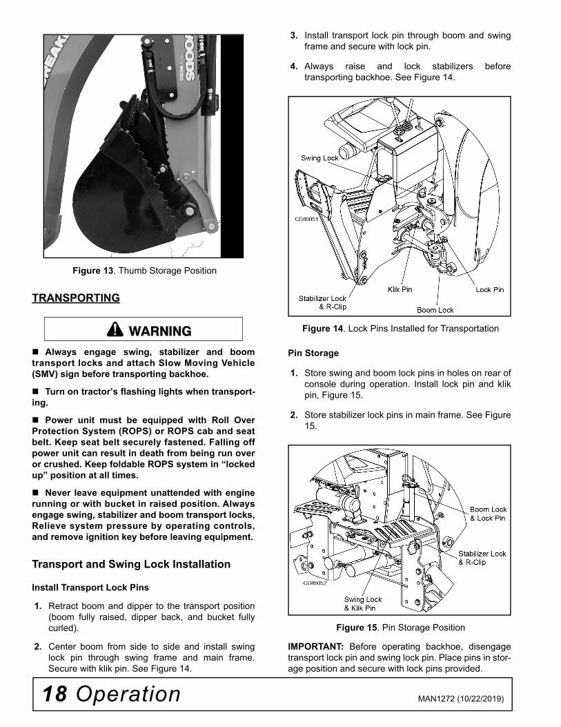
Figure 13. Thumb Storage Position
TRANSPORTING
Always engage swing, stabilizer and boomtransport locks and attach Slow Moving Vehicle(SMV) sign before transporting backhoe.
Turn on tractor’s flashing lights when transport-ing.
Power unit must be equipped with Roll OverProtection System (ROPS) or ROPS cab and seatbelt. Keep seat belt securely fastened. Falling offpower unit can result in death from being run overor crushed. Keep foldable ROPS system in “lockedup” position at all times.
Never leave equipment unattended with enginerunning or with bucket in raised position. Alwaysengage swing, stabilizer and boom transport locks,Relieve system pressure by operating controls,and remove ignition key before leaving equipment.
Transport and Swing Lock Installation
Install Transport Lock Pins
1. Retract boom and dipper to the transport position(boom fully raised, dipper back, and bucket fullycurled).
2. Center boom from side to side and install swinglock pin through swing frame and main frame.Secure with klik pin. See Figure 14.
3. Install transport lock pin through boom and swingframe and secure with lock pin.
4. Always raise and lock stabilizers beforetransporting backhoe. See Figure 14.
Figure 14. Lock Pins Installed for Transportation
Pin Storage
1. Store swing and boom lock pins in holes on rear ofconsole during operation. Install lock pin and klikpin, Figure 15.
2. Store stabilizer lock pins in main frame. See Figure15.
Figure 15. Pin Storage Position
IMPORTANT: Before operating backhoe, disengagetransport lock pin and swing lock pin. Place pins in stor-age position and secure with lock pins provided.
�������

Operation 19MAN1272 (10/22/2019)
BACKHOE REMOVAL AND STORAGE
The only time the backhoe may be operatedfrom a position other than the operator seat isduring backhoe attachment and removal. Operatormust:
• Read Mounting Kit Manual instructions onattaching and removing backhoe and useextreme care.• Always stand between rear tire and backhoestabilizer arms or along side of tractor to avoidbeing trapped should the boom swing controlbe accidentally activated.
Keep all persons away from operator controlarea while performing adjustments, service, ormaintenance. Remove seat and upper support assemblybefore installing or removing backhoe from powerunit. Failure to comply may result in equipment fail-ure and/or personal injury. Keep feet away from under backhoe to preventcrushing should the backhoe suddenly drop.
3-Point Mount Removal1. Operate tractor at low engine idle.
2. Position tractor on a hard level surface, removeswing lock pin and transport bar, and center thebackhoe boom.
3. Lower stabilizers and take weight of backhoe off ofrear tractor tires.
4. Lower boom and dipper to form 90-degree angleand rest bucket on the ground. See Figure 16.
5. Remove pin that attaches top link to tractor.Remove lower 3-point arms from backhoe. Placeblocks under mainframe and raise stabilizers tolower backhoe mainframe onto blocks. Blockbackhoe as necessary to make it stable.
6. Shut off tractor engine and disconnect hydraulicsystem.
4-Point Sub-Frame Mount Removal1. Locate the sub-frame mounting kit manual that
came with your sub-frame kit.
NOTE: Sub-frames are different for each tractor.See sub-frame installation instructions for partlocation details
2. Operate tractor at low engine idle.
3. Position tractor on a hard level surface, center thebackhoe boom and install swing transport lock pin.
4. Raise boom and remove boom transport lock pin5. Remove stabilizer transport lock pins, lower
stabilizers and take weight of backhoe off of reartractor tires.
6. Lower boom and dipper to form 90-degree angleand rest bucket on the ground.
7. Remove the seat assembly.
8. Remove klik pins from bolt and nut assemblies.
9. Use 1-1/2 inch open end wrench supplied with themounting kit to remove hex nuts. Return wrench tostorage position.
10. Use the boom to relieve excess pressure on 1-inchbolts and remove bolts.
11. Tilt backhoe main frame using boom cylinder toseparate slots on the backhoe brackets from thetractor brackets.
12. Raise stabilizers (to lower backhoe) until backhoebrackets slide out of hooks on the sub-frame.Lower backhoe approximately 1-1/2 inch.
13. Move tractor forward to clear backhoe brackets.14. Place 6 inch blocks under backhoe mainframe and
raise stabilizers to lower backhoe to the storageposition on blocks. Boom and dipper should be at90-degree angle. Install stabilizer and boom lockpins (Figure 16)
15. Disconnect hydraulic system.
Figure 16. Storage Position
Disconnect Tractor HydraulicsFor Backhoe Powered with Auxiliary PumpDisengage the PTO, stop tractor engine and removekey. Remove pump from PTO and secure it on back-hoe. Move tractor carefully away from backhoe.
������
�������

20 Operation MAN1272 (10/22/2019)
For Tractors with Open-Center Valves NOTE: See the sub-frame mounting kit manual that fitsyour tractor for specific instructions.Stop tractor and remove key.Disconnect pressure and return hoses. Connect tractorpressure and return hoses together to complete open-center circuit. See Figure 17.IMPORTANT: Circuit must be complete to preventdamage to tractor hydraulic system.Connect backhoe pressure and return hoses togetherfor storage. See Figure 17.
Figure 17. Tractors with Open-Center Valves
PRE-OPERATION CHECK LIST(OWNER'S RESPONSIBILITY BEFORE EACH USE)
The operator should perform the following check listbefore operating backhoe.
___ Check that backhoe is properly and securelyattached to tractor.
___ Make sure all hydraulic connections are tight andall hydraulic lines and hoses are in good condi-tion before engaging tractor PTO.
___ Check that there are no leaks in the hydraulicsystem. Before operating, all hydraulic hosesmust be routed properly and not be twisted, bentsharply, kinked, pulled tight or frayed.
Before working on backhoe, extend boom and dip-per-stick and place bucket on ground. Shut off tractorengine. Make sure that all system pressure has beenrelieved by operating controls before maintenance,service, or disconnecting any hydraulic lines.___ During inspection, check that all nuts and bolts
are secure and clevis pins are properly cotterpinned.
___ Make sure only original equipment high-strengthtop link pin, provided with tractor, is used toattach top link to tractor.
___ Use two 3/4" x 3-1/2" grade 5 bolts to mount toplink to backhoe.
___ Make sure tractor lower lift arm stabilizers (blocksor chains) are positioned to prevent lift arms andbackhoe from swaying.
___ Place all backhoe controls in neutral positionbefore starting tractor engine.
___ Check hydraulic reservoir level.
�������

Owner Service 21MAN1272 (10/22/2019)
OWNER SERVICEThe information in this section is written for operatorswho possess basic mechanical skills. If you need help,your dealer has trained service technicians available.For your protection, read and follow the safety informa-tion in this manual.
Before working on backhoe, extend boom anddipperstick and place bucket on ground. Shut offtractor engine. Make sure that all system pressurehas been relieved by operating controls beforemaintenance, service, or disconnecting anyhydraulic lines.
Always wear relatively tight and belted clothingto avoid getting caught in moving parts. Wearsturdy, rough-soled work shoes and protectiveequipment for eyes, hair, hands, hearing, and head;and respirator or filter mask where appropriate.
HYDRAULICS
Keep hands and body away from pressurizedlines. Use paper or cardboard, not hands or otherbody parts to check for leaks. Wear safety goggles.Hydraulic fluid under pressure can easily penetrateskin and will cause serious injury or death. Make sure that all operating and service person-nel know that if hydraulic fluid penetrates skin, itmust be surgically removed as soon as possible bya doctor familiar with this form of injury or gan-grene, serious injury, or death will result. CONTACT A PHYSICIAN IMMEDIATELY IF FLUIDENTERS SKIN OR EYES. DO NOT DELAY. Hydraulic oil and components get hot duringoperation. Let cool before performing any mainte-nance.
Hydraulic Hoses and FittingsHydraulic hoses are severely worked on a backhoe.Examine them daily and replace if necessary. Hoserouting is very important. Make certain hoses can movefreely, without kinking, and cannot be damaged or cutby backhoe action.
When tightening hoses and fittings, always use twowrenches: one to hold hose and one to tighten fitting.This will prevent hose from twisting and kinking.
Always back lock nut off and screw fitting all the way infor fittings that use O-rings for sealing. Then hold inposition and tighten lock nut.IMPORTANT: Fittings with O-rings and flange do notrequire additional sealant; replace damaged O-rings.
Relief Valve (Figure 18)This valve is pre-set at the factory to prevent systempressure from exceeding 2465 psi. WARNING! Do not attempt to reset the valve for open-center hydraulic systems. If valve is malfunctioning,replace it with an authorized factory replacement partor have service done by a qualified dealer.
Figure 18. Relief Valve, BH85 & BH100
LUBRICATION
Keep all persons away from operator controlarea while performing adjustments, service, ormaintenance.It is recommended that all fittings be lubricated daily orevery eight hours of operation. In very wet or dry condi-tions, lubricate every four hours of operation. See Fig-ure 19 and Lubrication and Maintenance Scheduleon Pg. 22
Use an SAE multi-purpose type grease for all locationsshown unless otherwise specified. Be sure to clean fit-ting thoroughly before using grease gun. One goodpump of most guns is enough.
IMPORTANT: Do not let excess grease collect on oraround parts, particularly when operating in sandyareas.
�������
CAUTION
�������
�������

22 Owner Service MAN1272 (10/22/2019)
Position backhoe for easy lubrication by placing boomand dipper at 90° to each other with bucket cutting
edge vertical and teeth resting on ground. Lower stabi-lizers to lubricate cylinders.
Figure 19. Lubrication Points
CLEANING
After Each Use● Remove large debris such as clumps of dirt, grass,
crop residue, etc. from machine.● Inspect machine and replace worn or damaged
parts.● Replace any safety decals that are missing or not
readable.
Periodically or Before Extended Storage● Clean large debris such as clumps of dirt, grass,
crop residue, etc. from machine.● Remove the remainder using a low-pressure water
spray.1. Be careful when spraying near scratched or torn
safety decals or near edges of decals as waterspray can peel decal off surface.
2. Be careful when spraying near chipped orscratched paint as water spray can lift paint.
3. If a pressure washer is used, follow the adviceof the pressure washer manufacturer.
● Inspect machine and replace worn or damagedparts.
● Sand down scratches and the edges of areas ofmissing paint and coat with Woods spray paint ofmatching color (purchase from your Woodsdealer).
● Replace any safety decals that are missing or notreadable (supplied free by your Woods dealer).See Safety Decals section for location drawing.
● Temperature changes can cause backhoe to moveduring storage. Store in a clean, dry place. Putwaterproof cover over backhoe if stored outside.
DISPOSALIf the backhoe becomes worn past its usable life, dis-pose of it according to local ordinances. DO NOT usethe backhoe and its individual components for anythingother than their intended use.
9. Boom cylinder base end (2 places)10. Boom pivot11. Boom cylinder rod end12. Swing frame pivot (top & bottom)13. Swing cylinder rod end (left & right)14. Swing cylinder pivot
(left & right, top & bottom)15. Stabilizer base end (left & right)16. Stabilizer rod end (left & right)
1. Bucket link pivot2. Bucket cylinder rod end3. Guide link pivot4. Bucket pivot5. Bucket cylinder base end6. Dipper cylinder rod end7. Dipper pivot8. Dipper cylinder base end

Owner Service 23MAN1272 (10/22/2019)
BACKHOE LUBRICATION & MAINTENANCE SCHEDULEMAINTENANCE REQUIREMENT
SERVICEINTERVAL
NOTES
Lubricate points as shown in Figure 19 with SAE multi-purpose grease.
8 hours, or daily In very wet or dry conditions, lubricate after every 4 hours of operation.
Inspect hydraulic hoses for damage or leaking.
8 hours, or daily Replace if hose is kinked or if hose cover is cracked or damaged.
Check hydraulic fluid level in reservoir or tractor sump.
8 hours, or daily Refer to PTO Pump Kit manual, or tractor manual for fluid specifications.
Remove large debris such as clumps of dirt, grease etc.
8 hours, or daily
Inspect and replace worn or damaged parts.
8 hours, or daily
Inspect and replace any safety decals that are missing, or not readable.
8 hours, or daily Safety decals are available at no charge from your Woods dealer.
Make sure that shields and guards are properly installed and in good condition.
8 hours, or daily
Make sure that all fasteners are installed and are properly torqued.
8 hours, or daily Fasteners in plastic materials only need to be snug. Do not overtighten. Do not over-tighten capscrews used to retain pivot pins.
Change oil and filter in backhoe reser-voir, (if equipped).
After first 20 hours Refer to PTO Pump Kit manual for fluid specifications.
Clean and thoroughly inspect painted surfaces of machine.
250 hours, or annually
Inspect pins and replaceable bearings. 250 hours, or annually
Inspect all hydraulic components for leaks or damage.
250 hours, or annually
Inspect and replace any safety decals that are missing, or not readable.
250 hours, or annually Safety decals are available at no charge from your Woods dealer.
Inspect seat and attaching hardware 250 hours, or annually
Inspect bucket teeth and replace as needed.
250 hours, or annually
Make sure that all fasteners are installed and torqued properly.
250 hours, or annually Or before putting into service after extended storage.Refer to PTO Pump Kit manual for fluid specifications.
Change oil and filter in backhoe reser-voir, (if equipped).
250 hours, or annually
Replace all hydraulic hoses. 500 hours, or 5 years

24 Troubleshooting MAN1272 (10/22/2019)
TROUBLESHOOTINGPROBLEM POSSIBLE CAUSE SOLUTION
Noisy pump caused by cavitation Oil too heavy Change to proper viscosity.
Oil filter plugged Replace filter.
Suction line plugged or too small Clean line and check for size.
Suction line kinked Replace line.
Oil heating Oil supply low Fill reservoir.
Contaminated oil Drain reservoir, change filter, and refill with clean oil.
Setting of relief valve too high or too low
Set to correct pressure.
Pump operating too fast Do not exceed 540 RPM PTO speed.
Shaft seal leakage Worn shaft seal Replace shaft seal.
Foaming oil Low oil level Fill reservoir.
Air leaking into suction line Tighten fittings.
Wrong kind of oil Drain and refill reservoir with non-foaming oil.
Moisture in oil Keep oil temperature below 180° and continue to operate as oil dries out, or replace oil and purge system if foaming is excessive.
Boom drops as dipper or bucket cylinder lever is activated while boom control is in raised position
Load check valve leaking Clean or replace check valve assembly.
Jerky operation Hydraulic hoses plumbed incorrectly
Check hydraulic plumbing schematic and correct hose routing as required.

Dealer Service 25MAN1272 (10/22/2019)
DEALER SERVICEThe information in this section is written for dealer ser-vice personnel. The repair described here requiresspecial skills and tools. If your shop is not properlyequipped or your mechanics are not properly trained inthis type of repair, it may be more time and cost effec-tive to replace complete assemblies.
Keep hands and body away from pressurizedlines. Use paper or cardboard, not hands or otherbody parts to check for leaks. Wear safety goggles.Hydraulic fluid under pressure can easily penetrateskin and will cause serious injury or death.
Make sure that all operating and service person-nel know that if hydraulic fluid penetrates skin, itmust be surgically removed as soon as possible bya doctor familiar with this form of injury or gan-grene, serious injury, or death will result.
CONTACT A PHYSICIAN IMMEDIATELY IF FLUIDENTERS SKIN OR EYES. DO NOT DELAY.
Before working on backhoe, extend boom anddipperstick and place bucket on ground. Shut offtractor engine. Make sure that all system pressurehas been relieved by operating controls beforemaintenance, service, or disconnecting anyhydraulic lines.
Always wear relatively tight and belted clothingto avoid getting caught in moving parts. Wearsturdy, rough-soled work shoes and protectiveequipment for eyes, hair, hands, hearing, and head;and respirator or filter mask where appropriate.
Never strike a pivot pin or punch with a nailhammer because the face may chip, possiblyresulting in an eye or other serious injury. Use asoft face hammer.
BH85 & BH100
HYDRAULIC VALVE REPAIR (FIGURE 20)
Valve repair should be accomplished in a clean workplace. Photograph or note the configuration of the partsbefore disassembling valve and control linkage. Thiswill make reassembly easier.
System Relief Valve
Adjustment of system relief pressure must bedone by a qualified, experienced dealership. Incor-rect adjustment can result in system failures andserious personal injury.No individual parts are available for relief valve.Replace entire assembly if required.
Pressure Setting AdjustmentNOTE: Before changing the pressure setting on thevalve, determine tractor hydraulic system pressure.Many tractors do not create 2500 psi. If your tractordoes not create 2500 psi, changing the relief valve set-ting will not improve the backhoe performance.To adjust relief valve setting, place a 3000 psi pressuregauge in the line attached to the valve inlet (IN) port.Remove cap from top of main relief (6, Figure 20). Turnadjusting screw clockwise to increase pressure andcounter clockwise to decrease pressure. Start tractorand set throttle for full engine speed. Move right stabi-lizer control lever to raise stabilizer to transport positionand hold the lever so full pressure builds. Adjust screwto attain 2465 psi for BH85 & BH100. Shut off tractorand replace cap.
Port Relief ValvesPressure settings on port relief valves are preset at thefactory. Although they are adjustable, they must not bereset in the field using backhoe hydraulic system. Anincorrect setting could cause hydraulic pump to fail orbackhoe cylinder rods to buckle.
Replace Port Relief ValvesIt is not necessary to remove the entire valve assemblyfrom the console to replace individual port relief valves.Be sure to install valve cartridges set at the correctpressure. Valves are similar and can be easily mixedup. IMPORTANT: Valve cartridges have small sealingwashers attached to them. When replacing valve,check cavity in valve housing for any loose washers.
Load Check Valve ReplacementThe load check valves (11) are located between thevalve work ports. Remove load check assembly using
�������
CAUTION
Port Relief Valve Pressure Setting Cartridge 8 2465 psiCartridge 7 2610 psiCartridge 9 3045 psi
�������

26 Dealer Service MAN1272 (10/22/2019)
a large screwdriver. Inspect seat in valve housing forany dirt or damage. Replace load check if required.
Spool RepairWhenever repairing spools or positioner, replace valvespool seals which are included in the spool seal repairkit.
DisassembleRemove the joystick assembly and/or single lever con-trol from valve. Remove the plastic dust cap from posi-tioner (3, 4). Unscrew the positioner assembly fromvalve housing. Push spool (1, 2) out of housing.
Secure spool in vise taking care not to scratch or nickthe outer surface. Unscrew the positioner from spool.Remove brass sleeve (15) and O-ring (16) from posi-tioner end of valve housing. Remove O-ring (16) andflange washer (17) from control lever end of valvehousing. The boom spool has a special sleeve with twoO-rings.
Check spools, replace if nicked and scratched.
Carefully inspect spool bore in valve housing. If deepscratches or scouring is present, entire valve should bereplaced.
AssembleClean threads on positioner and spool. Apply a remov-able-type thread locking compound to male threadsand assemble positioner to spool. Torque to 85±15 in-lbs.Apply clean oil to O-ring (16) and install, along withbrass sleeve (15) on spool housing positioner end.Slide spool into valve housing. Torque positioner endcap (3, 4) to 70±15 in-lbs.Reassemble the O-ring (16) and flanged washer (17)on control lever end of spool. Boom spool does not usea flange washer.Position spool wipers (A) (Figure 18) on swing, dipper,and bucket spools in linkage plate. Reinstall controllinkage. Note the screws installed in the boom and dip-per spools should be tightened until snug, then backedoff approximately ½ turn to allow free movement of thejoystick.
Figure 20. BH85 & BH100 Control Valve Assembly
ADJUST CONTROL VALVE LINKAGE Reconnect control linkage to valve. Control handles should be positioned as shown. Referto parts list on page 40 for details.
When completing a maintenance function on the valve,perform a functional test by placing control handles intheir various positions and make certain the correctoperation occurs corresponding to the decals on the
A. Valve - 6 Spool MBLK 2465 PSI1. Spool 4 position float2. Spool 3 position3. Spool pos cont asy 4 pos4. Spool pos cont asy 3 pos5. Control asy-stabilizer6. Valve relief 2465 psi7. Valve relief 2610 psi8. Valve relief / anti-cav 2465 psi
9. Valve relief / anti-cav 3045 psi10. Plug, 3/4 SAE M w/ o-ring11. Valve load check asy12. Handle control-stabilizer13. Plug - PBY(if required)14. Sleeve w/ o-rings (boom spool
only)
15. Sleeve, lower16. O-ring17. Flange washer
Dealer Service 27MAN1272 (10/22/2019)
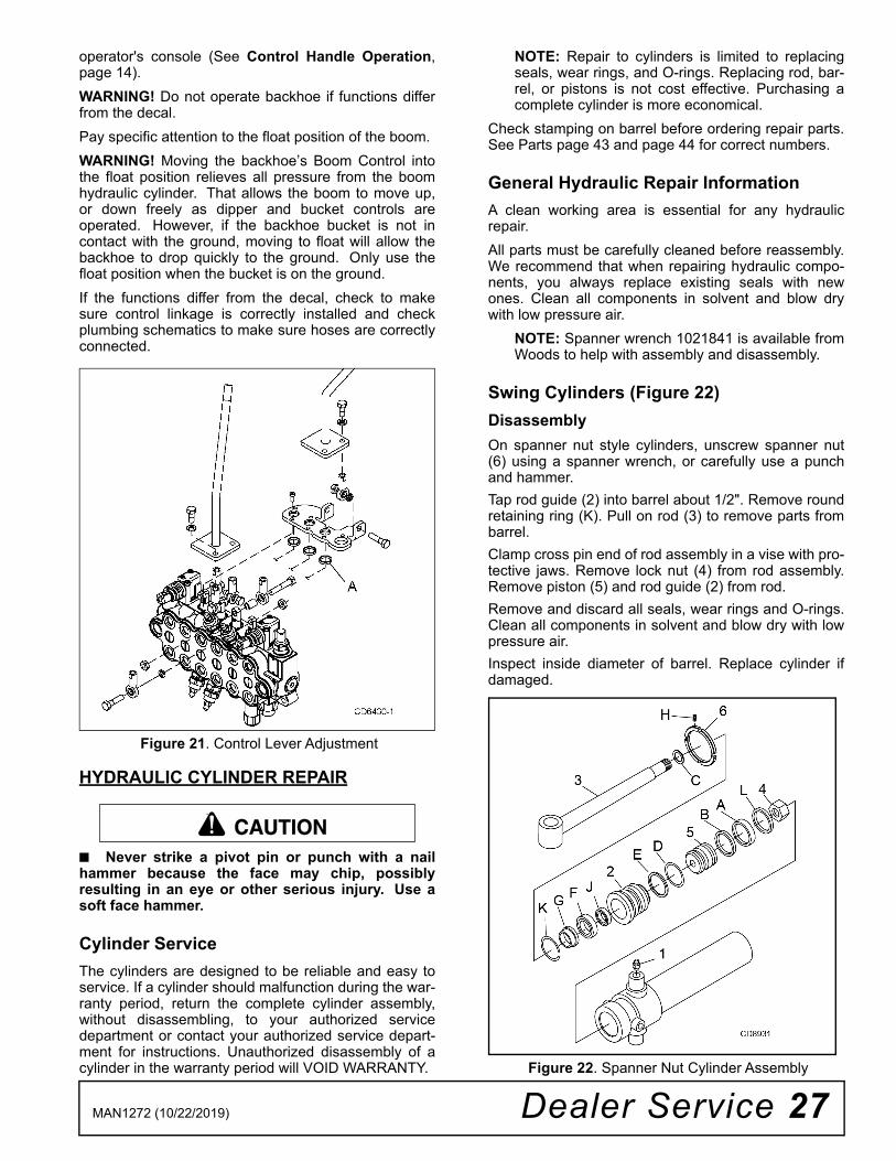
operator's console (See Control Handle Operation,page 14). WARNING! Do not operate backhoe if functions differfrom the decal. Pay specific attention to the float position of the boom. WARNING! Moving the backhoe’s Boom Control intothe float position relieves all pressure from the boomhydraulic cylinder. That allows the boom to move up,or down freely as dipper and bucket controls areoperated. However, if the backhoe bucket is not incontact with the ground, moving to float will allow thebackhoe to drop quickly to the ground. Only use thefloat position when the bucket is on the ground.If the functions differ from the decal, check to makesure control linkage is correctly installed and checkplumbing schematics to make sure hoses are correctlyconnected.
Figure 21. Control Lever Adjustment
HYDRAULIC CYLINDER REPAIR
■ Never strike a pivot pin or punch with a nailhammer because the face may chip, possiblyresulting in an eye or other serious injury. Use asoft face hammer.
Cylinder ServiceThe cylinders are designed to be reliable and easy toservice. If a cylinder should malfunction during the war-ranty period, return the complete cylinder assembly,without disassembling, to your authorized servicedepartment or contact your authorized service depart-ment for instructions. Unauthorized disassembly of acylinder in the warranty period will VOID WARRANTY.
NOTE: Repair to cylinders is limited to replacingseals, wear rings, and O-rings. Replacing rod, bar-rel, or pistons is not cost effective. Purchasing acomplete cylinder is more economical.
Check stamping on barrel before ordering repair parts.See Parts page 43 and page 44 for correct numbers.
General Hydraulic Repair InformationA clean working area is essential for any hydraulicrepair.All parts must be carefully cleaned before reassembly.We recommend that when repairing hydraulic compo-nents, you always replace existing seals with newones. Clean all components in solvent and blow drywith low pressure air.
NOTE: Spanner wrench 1021841 is available fromWoods to help with assembly and disassembly.
Swing Cylinders (Figure 22)Disassembly On spanner nut style cylinders, unscrew spanner nut(6) using a spanner wrench, or carefully use a punchand hammer. Tap rod guide (2) into barrel about 1/2". Remove roundretaining ring (K). Pull on rod (3) to remove parts frombarrel.Clamp cross pin end of rod assembly in a vise with pro-tective jaws. Remove lock nut (4) from rod assembly.Remove piston (5) and rod guide (2) from rod. Remove and discard all seals, wear rings and O-rings.Clean all components in solvent and blow dry with lowpressure air.Inspect inside diameter of barrel. Replace cylinder ifdamaged.
Figure 22. Spanner Nut Cylinder Assembly
CAUTION

28 Dealer Service MAN1272 (10/22/2019)
AssemblyLubricate O-rings and seals with clean hydraulic fluid.Install back-up washer (E) on rod guide (2), then installO-ring (D) in exterior O-ring groove of rod guide. Installrod seal (F) into inner groove of rod guide with openportion of V-groove toward piston. Place rod wiper (G) in outer rod guide groove. Slide rodguide assembly (2) onto rod (3). Place wear ring (A) innarrow groove of piston. Place piston seal (B) in widepiston groove. Place piston ring (J) in narrow groove inrod guide.Lightly coat rod threads with hydraulic oil and slide O-ring (C) over threads and into groove. Install piston (5)onto rod (3) with wear ring on side away from rodguide. Clean threads of rod and apply Loctite® primer7649 and removable thread locker 243. Install lock nut(4) and torque to 175 lbs-ft for swing cylinder.Compress wear ring and piston seal and carefullyinsert piston and rod assembly into barrel. Use care toprevent damage while installing. Carefully push or tap rod guide (2) into barrel just pastgroove inside barrel. Insert retaining ring (K) intogroove and pull rod (1) to seat rod guide (2) againstring. Screw spanner nut (4) into rod guide (2) using aspanner wrench, or carefully use a punch and hammer.
Cylinder Disassembly (except swing)Remove set screw (H) from outside of rod guide (2).Using a spanner wrench or a hammer and punch,unscrew rod guide from cylinder barrel. Remove rodassembly (3) from barrel.Clamp cross tube of rod assembly in a vise andremove nut (4) from rod. Remove piston (5) from rodand slide rod guide off of rod. Remove and discard allseals, wear rings and O-rings. Clean all components in
solvent and blow dry with low pressure air. Inspectinside diameter of barrel. Replace cylinder if damaged.
AssemblyFor these assembly instructions the front surface of thethreaded rod guide with two holes will be referred to asthe "rod guide face."
Lubricate O-rings and seals with clean hydraulic fluid.Install back-up washer (E) on rod guide (2), and theninstall O-ring (D) in exterior O-ring groove of rod guide.Make sure that the back-up ring is located closest tothe rod guide face. Place rod wiper (G) in outer rodguide groove. Install rod seal (F) into the secondgroove from the rod guide face with the open portion ofV-groove toward piston. Install wear ring (J) in remain-ing groove. With all rod guide seals installed, slide therod guide assembly onto rod (3).
Coat O-ring (C) with oil and slide over rod threads andinstall in groove on rod. Slide piston (5) onto rod. Cleanthreads of rod and apply Loctite®1 primer 7649 andremovable thread locker 243. Install nut (4) and torqueto 275lbs-ft. Install wear ring (A) and piston seal (B)into grooves on outside of piston. Note that piston sealconsists of two pieces.
Compress wear rings and piston seals and carefullyinsert piston and rod assembly into barrel. Use care toprevent damage while installing. Carefully screw rodguide (2) into barrel using a spanner wrench, or apunch and hammer. Align drilled hole in guide and bar-rel and install new set screw (H).
.
Figure 23. Cylinder Assembly
1. Loctite is a registered trademark of the Henkel Loctite Corporation.
A. Wear ringB. Piston sealC. O-ringD. O-ringE. Backup ringF. Rod seal
G. Rod wiperH. Set screwJ. Wear ring2. Rod guide3. Rod assembly4. Nut5. Piston
1021841 - Spanner wrench1021842 - Replacement pin kit
for spanner wrench

Assembly 29MAN1272 (10/22/2019)
ASSEMBLY
Backhoe assembly is the responsibility of the WOODSdealer. The backhoe should be delivered to the ownercompletely assembled, lubricated and adjusted for nor-mal operating conditions.
Set backhoe up as received from the factory with theseinstructions and illustrations.
The backhoe must only be mounted with a tractor 3-point hitch using WOODS 3-Point Mount Kit or aWOODS Sub-Frame Kit. See WOODS 3-Point Mountmanual for mount installation instructions.
When mounting this backhoe on a tractor using a sub-frame mount, special assembly instructions (which arecontained in another manual furnished with the sub-frame) apply to some of the assembly procedures.
The backhoe is shipped partially assembled. Assemblywill be easier if components are aligned and looselyassembled before tightening hardware.
NOTE: References to right, left, forward and rearwarddirections are determined from the backhoe operatorseat position facing the backhoe.
Figure 24. Backhoe Directions
GENERAL ASSEMBLY INSTRUCTIONS
Keep all persons away from operator controlarea while performing adjustments, service, ormaintenance.
Only mount this backhoe on Category 1, 2, or 3Ntractors under 100 hp with 1800 lb. lift capacity at24” behind 3-point lift arm hitch balls.
Removing Backhoe from Pallet
■ Lift and move backhoe carefully with ade-quate equipment and proper training.
The backhoe is shipped partially assembled in awooden pallet. To remove the backhoe from the palletuse a lifting strap rated for at least 3000 lbs and posi-tion it as shown in Figure 25, support backhoe andcarefully remove straps and pin and fasten it to the pal-let.
WARNING! Use lifting strap certified to ASME B30.9rated at a minimum capacity of 3000 lbs.
Figure 25. Lifting Backhoe
Stabilizer Installation (Figure 25)
Remove stabilizer arms from pallet.
Remove pivot pins (4) from their shipping position.Attach stabilizer arm (2) to main frame (1) with pivot pin(4) and secure with snap ring (6).
Attach stabilizer cylinder (3) to stabilizer arm with pivotpin (5) and secure with two cotter pins (7).
Insert transport lock pins (8) to hold stabilizers in raisedposition.
�������
�������

30 Assembly MAN1272 (10/22/2019)
Figure 26. Stabilizer Arm Assembly - Left Side
Bucket Installation (Figure 27)
■ Buckets are heavy and can cause musclestrain or back injury. Use lifting aids and proper lift-ing techniques when installing.
1. Remove pivot pins (4 & 5) from end of bucket link(3) and dipper (1).
2. Attach bucket (2) to the end of the dipper with pivotpins (5).
3. Attach bucket link (3) to the bucket using pivot pin(4).
4. Secure both pins using bolts (6) and lock nuts (7).
Figure 27. Bucket Installation
NOTE: 12", 15", 18", 24" and 36" buckets are availablewith this backhoe.
HYDRAULIC INSTALLATION
Keep hands and body away from pressurizedlines. Use paper or cardboard, not hands or otherbody parts to check for leaks. Wear safety goggles.
Hydraulic fluid under pressure can easily penetrateskin and will cause serious injury or death. Make sure that all operating and service person-nel know that if hydraulic fluid penetrates skin, itmust be surgically removed as soon as possible bya doctor familiar with this form of injury or gan-grene, serious injury, or death will result. CONTACT A PHYSICIAN IMMEDIATELY IF FLUIDENTERS SKIN OR EYES. DO NOT DELAY. Make sure shields and guards are properlyinstalled and in good condition. Replace if damaged.
1. Main frame2. Stabilizer arm w/pad3. Stabilizer cylinder4. Pin 1.25 x 7.325. Pin 1.25 x 5.006. Retaining ring .050 x 1.1567. Cotter pin 3/16 x 1-1/28. Transport lock pin
�������
1. Dipper2. Bucket3. Bucket link4. Bucket link pin5. Bucket pivot pin6. HHCS 3/8 NC x 37. Lock nut 3/8 NC
�������

Assembly 31MAN1272 (10/22/2019)
Power to the backhoe can be supplied directly from thetractor hydraulic system. A hydraulic requirement of10 gallons per minute and 2500 PSI is necessary tooperate the backhoe efficiently. 1/2" diameterhoses (SAE 100 R1 with 3000 PSI working pres-sure) should be used to connect the hydraulic sourceto the backhoe valve. These hoses must be longenough to allow ease of removal or attachment ofbackhoe. Hoses must include external shielding to pre-vent oil from spraying on operator if hose fails.
Open-Center Valve
Locate the IN and OUT ports on the control valve underthe operator’s platform. Connect hoses to these ports.Attach male and female couplers compatible to thetractor on opposite end of the hoses.
IMPORTANT: The backhoe will not function if oil isrouted backwards through the valve. Connect the trac-tor PRESSURE hose to the backhoe valve IN port andthe RETURN hose to the backhoe valve OUT port.Tighten all fittings securely. Start engine and run at lowRPM. Activate hydraulic circuit and check for leaks.
IMPORTANT: Damage to valve will result if oil is routedbackwards through the valve.
IMPORTANT: Valve damage will occur if back pressureexceeds 450 psi.
IMPORTANT: Do not route return oil through tractorremote valve. Use a low pressure port, such as a motorreturn port.
NOTE: See the sub-frame mounting kit manual for spe-cific tractor and hydraulic hose kit instructions.
Figure 28. Backhoe Valve Ports
OPTIONAL EQUIPMENT
1006610KT Stabilizer Street Pad Installation (Figure 29)1. Attach two rubber stabilizer pads (1) to the bottom
of stabilize pad using three lock nuts (2).
2. Repeat step for opposite side stabilizer.
Figure 29. Stabilizer Pad Installation
6045355 3-Point Mount KitSee 3-Point Mount Kit manual for installation instruc-tions.
604345 PTO Pump KitSee PTO Pump Kit manual for installation instructions.
602759 Mechanical Thumb Kit (Figure 30)
■ Never strike a pivot pin or punch with a nailhammer because the face may chip, possiblyresulting in an eye or other serious injury. Use asoft face hammer.1. Disengage boom lock pin, lower boom and place
bucket on the ground.2. Remove hardware and pivot pin that attaches
bucket to the end of the dipper. Reuse hardwarewhen installing thumb pivot pin (5).
3. Place thumb (1) over bucket lugs and align holes.4. Insert pin (5) to secure thumb and bucket to dipper.
Reuse previously removed hardware.5. Align thumb channel (2) with thumb and insert pin
(7). Secure pin with hex bolt (15) and lock nut (16).6. Install thumb bracket (3) using three hex bolts (13)
and lock nuts (14).
1. Rubber stabilizer pad
2. 3/8 NC Lock nut
�������

32 Assembly MAN1272 (10/22/2019)
7. Insert thumb tube (4) into thumb channel andsecure together using pin (8) and klik pin (9).
8. Rotate thumb tube up and connect to the thumbbracket using pin (6). Secure pin with hex bolt (15)and lock nut (16).
NOTE: Thumb compatible with 15”, 18”, and 24”buckets.
Figure 30. Mechanical Thumb Installation
Figure 31. Mechanical Thumb Installed
Hydraulic ThumbHydraulic thumb installed only at factory. See page 51for parts list.
1. Thumb BH85 / BH1002. Thumb channel3. Thumb bucket4. Thumb tube5. Pin 1.50 x 11.326. Pin 1.00 x 7.757. Pin 1.00 x 9.858. Swivel hitch pin 1 x 4-1/4 in.9. 1/4 x 1-3/4 klik pin
13. HHCS 1/2 NC x 6-1/214. Lock nut 1/2 NC flange15. HHCS 5/16 NC x 2-1/4 GR516. Lock nut 5/16 NC
DP9

Dealer Check Lists 33MAN1272 (10/22/2019)
DEALER CHECK LISTS
PRE-DELIVERY CHECK LIST(DEALER’S RESPONSIBILITY)
Inspect the backhoe (and sub-frame when applicable)thoroughly after assembly to be certain it is set upproperly before delivering it to the customer. The checklists are a reminder of points to inspect. Check off eachitem as it is found satisfactory or after proper adjust-ments are made.
___ Check all bolts to be sure they are tight. (Referto torque chart.)
___ Check that all lubrication points have beenlubricated. (Refer to lubrication diagram.)
___ Check that all cotter pins and safety pins areproperly installed.
___ Properly attach backhoe (and sub-frame whenapplicable) to tractor and make all necessaryadjustments. (Refer to sub-frame manual).
___ Check that optional hydraulic reservoir hasbeen serviced and that hydraulic system andall functions have been operated through fullcylinder stroke to purge air from system.
___ Make sure all hydraulic fittings are tight andhoses are properly routed and not twisted, bentsharply, kinked or pulled tight.
___ After pressurizing and operating all backhoefunctions, stop tractor and make sure there areno leaks in the hydraulic system. Follow allsafety rules when checking for leaks.
DELIVERY CHECK LIST(DEALER’S RESPONSIBILITY)
___ Present Operator's Manual (and sub-framemanual when applicable) and request that cus-tomer and all operators read it before operatingequipment.
___ Point out all safety features of the equipment.Explain the importance and meaning of allsafety decals and emphasize the potential haz-ards when not followed.
___ Show customer how to make adjustments.
___ Explain importance of lubrication and showlubrication points to customer.
___ Show customer the safe and proper proce-dures to be used when mounting, dismountingand storing backhoe (and sub-frame whenapplicable).
___ If backhoe is mounted to tractor 3-point hitch,explain the importance of the Saf-T-Lok limiter.Point out (as shown in Operator's Manual) thecorrect attachment and adjustment of the lim-iter.
___ Point out the correct mounting of the hydraulicpump and routing of the hoses. Explain thatduring operation, mounting, dismounting andstorage, care must be taken to prevent hosedamage from pulling, twisting and kinking.
___ Show customer the safe and proper proce-dures to be used when mounting, dismountingand storing backhoe (and sub-frame whenapplicable).
___ Point out Danger decal #618130 and explaineach bullet point.

34 Dealer Check Lists MAN1272 (10/22/2019)
NOTES

Parts 35MAN1272 (10/22/2019)
PARTS INDEX
BH85 & BH100MAIN FRAME ASSEMBLY . . . . . . . . . . . . . . . . . . . . . . . . . . . . . . 36 - 37
SWING FRAME ASSEMBLY . . . . . . . . . . . . . . . . . . . . . . . . . . . . . . . .38
BOOM ASSEMBLY. . . . . . . . . . . . . . . . . . . . . . . . . . . . . . . . . . . . . . . .39
DIPPER/BUCKET ASSEMBLY. . . . . . . . . . . . . . . . . . . . . . . . . . . . . . .40
VALVE HARDWARE. . . . . . . . . . . . . . . . . . . . . . . . . . . . . . . . . . . . . . .41
CONTROL VALVE ASSEMBLY . . . . . . . . . . . . . . . . . . . . . . . . . . . . . .42
SWING CYLINDER ASSEMBLY. . . . . . . . . . . . . . . . . . . . . . . . . . . . . .43
HYDRAULIC CYLINDER ASSEMBLY . . . . . . . . . . . . . . . . . . . . . . . . .44
HOSES & FITTINGS . . . . . . . . . . . . . . . . . . . . . . . . . . . . . . . . . . 45 - 46
MECHANICAL THUMB ASSEMBLY (OPTIONAL) . . . . . . . . . . . . . . . .47
HYDRAULIC THUMB ASSEMBLY (OPTIONAL) . . . . . . . . . . . . . 48 - 51
STABILIZER STREET PAD KIT (OPTIONAL) . . . . . . . . . . . . . . . . . . .51

36 Parts MAN1272 (10/22/2019)
BH85 & BH100 MAIN FRAME ASSEMBLY

Parts 37MAN1272 (10/22/2019)
MAIN FRAME ASSEMBLY PARTS LIST
REF PART QTY DESCRIPTION
1 602935RP 1 Main frame BH85 / BH1002 603735RP 2 Stabilizer arm3 1017808 2 Stabilizer pad4 603745RP 1 Console back5 603758RP 1 Console left6 603760RP 1 Console right7 ------ 1 Valve w/controls (see page 41)8 604340 1 Adjustable high back seat9 602224 2 Cylinder 2.95 x 1.50 x 14.00
10 603748RP 1 Console cover11 603754RP 1 Seat bracket12 1003828 1 Manual tube13 603749RP 1 Lower seat support14 603764RP 1 Upper seat channel15 603753RP 1 Seat handle16 70165 1 Handle grip17 78705 1 Extension spring22 1011884 4 Pin, 1.25 x 7.3223 37431 2 Pin,1.00 x 6.1024 602772 2 Pin 1.25 x 5.0025 55318 2 Hitch pin .75 x 6.2526 63236 8 Ring, ret .050 x 1.15627 1266 * 4 3/16 x 1-1/2 cotter pin
REF PART QTY DESCRIPTION
28 923 * 4 1/4 x 1-3/4 cotter pin29 W74058 2 Clamp .625 DIA steel cushion30 6698 * 3 Nut lock 3/8 NC ZP31 62153 * 2 3/8 NC x 1 hex flange32 24597 * 6 Bolt CRG 3/8 NC x 3/433 14350 * 12 Nut lock 3/8 NC flange34 1008291 * 3 Bolt CRG 5/16 NC x 2.5 GR535 W73163 * 10 Nut whiz 5/16 NC flange HD ZP36 74047 4 Spring nut 5/16 - 18 U-tapered37 6096 * 4 HHCS 5/16 NC x 3/4 GR5 ZP38 839 * 2 HHCS 3/8 NC x 1 GR5 ZP39 10380 * 1 HHCS 1/2 NC x 4 GR5 ZP40 765 * 1 Nut lock 1/2 NC ZP41 71851 * 3 HHCS 5/16 NC x 3/4 flange42 78285 4 Button head screw 5/16 NC x 3/4
ZP43 21757 1 Washer 3/8 STD SAE flat44 20973 * 4 Bolt CRG 3/8 NC x 1-1/4 GR5
618136 NS Complete Decal Set618137 NS Safety Decal Set
HHCS Hex Head Cap ScrewCRG Carriage
* Standard hardware, obtain locally

38 Parts MAN1272 (10/22/2019)
BH85 & BH100 SWING FRAME ASSEMBLY
REF PART QTY DESCRIPTION
1 602935RP 1 Main frame BH85 / BH1002 602934RP 1 Swing frame BH100
603604RP 1 Swing frame BH853 609665RP 1 Trunnion bar4 602220 2 Cylinder 2.48 x 1.26 x 11.008 1011874 2 Pin, 1.25 x 5.009 602774 2 Pin, 2.00 x 4.75
10 1012609 1 Pin, hitch 1.25 x 4.2511 604339 1 Pin, flag 1.50 x 5.9412 443029 2 Snap ring13 62043 1 Klik pin 1/4 x 1-3/414 37851 2 Bushing, 1-1/2 ID x 1-3/4 OD x 215 1020214 4 Bushing, 1.25 x 1.50 x 1.0016 603731 2 Bushing, 2.00 x 2.25 x 1.5017 14069 * 2 HHCS 1/2 NC x 3-1/4
REF PART QTY DESCRIPTION
18 765 * 2 Lock nut 1/2 NC ZP19 10509 * 2 HHCS 5/16 NC x 2-1/2 GR520 6778 * 2 Lock nut 5/16 NC21 12274 * 4 HHCS 5/8 NC x 2-1/422 19025 4 Nut, HFN 5/8 DRI-LOC patch23 57817 4 Washer 5/8 SAE flat hardened24 3379 * 1 HHCS 1/2 NC x 1-1/2 GR5 ZP25 11900 * 1 Lock nut 1/2 NC flange
HHCS Hex Head Cap ScrewHFN Hex Flange Nut
* Standard hardware, obtain locally

Parts 39MAN1272 (10/22/2019)
BH85 & BH100 BOOM ASSEMBLY
REF PART QTY DESCRIPTION1 602932RP 1 Boom BH100
603594RP 1 Boom BH852 602219 1 Cylinder 3.15 x 1.57 x 21.38 (BH100)
602217 1 Cylinder 3.15 x 1.57 x 17.38 (BH85)3 602222 1 Cylinder 2.95 x 1.57 x 22.25 (BH100)
602226 1 Cylinder 2.95 x 1.57 x 20.75 (BH85)4 1017747 1 Pin, 1.50 x 8.625 1017748 2 Pin, 1.50 x 9.786 602771 1 Pin, 1.25 x 7.087 62718 2 Snap ring .109 x 1.508 602773 1 Pin, 1.18 x 9.759 33000 1 Lynch pin 3/8 x 2-1/4
10 1020005 2 Restrictor, .125 9/16 ORB11 62367 2 Adapter 9/16 JICM 9/16 ORBM12 W74058 2 Clamp .625 DIA steel cushion
REF PART QTY DESCRIPTION13 1011843 1 Hose clamp14 1011844 1 Clamp18 1011842 2 Stud 1/4 - 20 UNC x 3.0019 ------ 2 Nut 1/4 - 20 UNC blind hole20 4529 * 2 Nut hex 5/16 NC ZP21 5288 * 2 Nut hex 1/4 NC22 5336 * 4 Washer 1/4 flat ZP23 FA254 2 Nut 1/4 NC Nylock ZP24 6250 * 2 HHCS 5/16 NC x 1-1/4 GR5 ZP25 6778 * 2 Lock nut 5/16 NC26 7747 * 2 HHCS 3/8 NC x 3 GR527 6698 * 3 Lock nut 3/8 NC ZP28 2290 * 1 HHCS 3/8 NC x 2-1/2 GR5 ZP
HHCS Hex Head Cap Screw* Standard hardware, obtain locally

40 Parts MAN1272 (10/22/2019)
BH85 & BH100 DIPPER / BUCKET ASSEMBLY
REF PART QTY DESCRIPTION1 602933RP 1 Dipper BH100
602945RP 1 Dipper BH852 602753 1 Bucket 12"
602754 1 Bucket 15"602755 1 Bucket 18"602756 1 Bucket 24"602757 1 Bucket 36"
602757D 1 Bucket, 36" Ditching (no teeth)3 602223 1 Cylinder 2.48 x 1.50 x 20.004 603582RP 1 Bucket link5 37835RP 2 Guide link6 602943 6 Plug, .551 x .4927 37851 4 Bushing 1-1/2 ID x 1-3/4 OD x 28 34014 2 Bushing, 1-1/4 x 1-1/2 x 1-1/29 24611 1 SMV sign
10 1004251 1 SMV bracket11 62484 1 Socket SMV emblem12 602771 1 Pin, 1.25 x 7.08
REF PART QTY DESCRIPTION13 37839 3 Pin, clevis 1.25 x 9.2514 1020014 1 Pin, 1.50 x 8.6115 601271 2 Rivet, blind .25 x .53 x .06 - .2519 5237 * 2 HHCS 5/16 NC x 1/2 GR520 6778 * 2 Lock nut 5/16 NC21 7447 * 4 HHCS 3/8 NC x 3 GR522 2290 * 1 HHCS 3/8 NC x 2-1/2 GR5 ZP23 6698 * 5 Lock nut 3/8 NC ZP24 ------ 2 Nut 1/4 - 20 UNC blind hole25 1031020 AR Tooth, bolt on 1.75 x 9.3026 6239 * AR Lock nut 5/8 NC27 602218 AR FSHCS 5/8 UNC x 2-1/2
AR As RequiredHHCS Hex Head Cap Screw
* Standard hardware, obtain locally

Parts 41MAN1272 (10/22/2019)
BH85 & BH100 VALVE HARDWARE
REF PART QTY DESCRIPTION
A 618139 1 6 spool monoblock valve repair(see page 41)
1 605185RP 2 Control handle2 37765 2 Boot, rubber control3 1042055 2 Knob - 1.88 DIA x 1/2 - 13 UNC4 605175RP 1 Plate, control linkage mount5 ------ 7 Screw, slotted head M5 - 0.8P x 12 mm
(included with item 1)6 ------ 3 Spool wiper (included with item 1)
10 37613 6 Rod end 5/16 NF female
REF PART QTY DESCRIPTION
11 37577 4 Washer, .328 x .463 x .09312 6250 * 4 HHCS 5/16 NC x 1-1/4 GR5 ZP13 4528 * 2 HHCS 5/16 NC x 1-3/4 GR514 604338 2 Sleeve, .328 x .463 x .57515 6778 * 6 Lock nut 5/16 NC16 24405 6 HHCS 5/16 NF x 3/4 GR5 ZP17 2472 * 6 Washer 5/16 lock ZP
HHCS Hex Head Cap Screw* Standard hardware, obtain locally

42 Parts MAN1272 (10/22/2019)
BH85 & BH100 CONTROL VALVE ASSEMBLY
REF PART QTY DESCRIPTION
A 618139 1 Valve - 6 Spool MBLK repair1 1011953 1 Spool 4 position float2 1011954 5 Spool 3 position3 33343 1 Spool POS cont ASY 4 POS4 1011955 5 Spool POS cont ASY 3 POS5 38628-1 2 Control Ass’y - Stabilizer6 33342 1 Valve relief 2030 PSI7 53380 2 Valve relief 2610 PSI
REF PART QTY DESCRIPTION
8 53381 3 Valve relief / anti-cav 2470 PSI9 602216 1 Valve relief / anti-cav 3045 PSI
10 38632-1 2 Plug, 3/4 SAE M w/ o-ring11 33339 6 Valve load check asy12 38629 2 Handle control - stabilizer13 1020211 1 Plug - PBY (if required)14 1034169 1 Sleeve w/ o-rings (boom spool only)NS 33346 6 Spool seal repair kit
HHCS Hex Head Cap ScrewNS not shown
* Standard hardware, obtain locally

Parts 43MAN1272 (10/22/2019)
SWING CYLINDER ASSEMBLY
REF PART QTY DESCRIPTION
A * 1 Wear ringB * 1 Piston sealC * 1 O-ringD * 1 O-ringE * 1 Backup ringF * 1 Rod sealG * 1 Rod wiperH * 1 Set screwJ * 1 Wear ringK * 1 Retaining ringL * 1 Piston ring
* Items A - L included in seal kit 606315
1 12296 2 Grease fitting 1/4 - 282 N/S 1 Rod guide3 N/S 1 Rod assembly4 N/S 1 Nut5 N/S 1 Piston6 N/S 1 Spanner nut
602220 2 Complete swing cylinder
N/S Not serviceable
REF PART QTY DESCRIPTION

44 Parts MAN1272 (10/22/2019)
HYDRAULIC CYLINDER ASSEMBLY
* Part Number Is Stamped On Cylinder Barrel Near Base End Port.Item 1. - Grease Fitting P/N 195 1/8 NPT (obtain locally)
Function* Complete Assembly
Base End Style
Retracted Length Bore Dia Rod Dia
Seal Kit (Includes A - H)
Stabilizer 602224 Tube 21.00 2.95 1.50 606316Dipper (BH85) 602226 Tang 29.75 2.95 1.57 606317Dipper (BH100) 602222 Tang 32.12 2.95 1.57 606317Boom (BH85) 602217 Clevis 25.62 3.15 1.57 606318Boom (BH100) 602219 Clevis 31.00 3.15 1.57 606318Bucket 602223 Tube 28.00 2.48 1.50 606319Thumb 602227 Tube 24.00 2.48 1.50 606319
Optional Spanner Wrench1021841 - Spanner wrench1021842 - Replacement Pins

Parts 45MAN1272 (10/22/2019)
BH85 HOSES & FITTINGS
HOSEREF PART QTY DESCRIPTION
A ------ 1 6 spool monoblock valve (see page 41)1 62367 15 Adapter 9/16 JICM 9/16 ORBM2 63558 11 90° adjustable elbow3 316004 2 Elbow 3/4 ORBM 3/4 JICM4 1020005 4 Restrictor, .125 9/16 ORB5 37508 2 Adapter .094 9/16 JICM 9/16 ORBM6 602776 2 Feedline BH85 & BH100
REF PART QTY DESCRIPTION
B 602212 2 Hose, 1/4 33 9/16 JICF 9/16 JICFC 602214 2 Hose, 1/4 47 9/16 JICF 9/16 JICFD 602215 2 Hose, 1/4 50 9/16 JICF 9/16 JICFE 606327 2 Hose, 1/4 22 9/16 JICF 9/16 JICFF 606306 1 Hose, 3/8 78 9/16 JICF 9/16 JICFG 606307 1 Hose, 3/8 79 9/16 JICF 9/16 JICFH 606308 1 Hose, 3/8 94 9/16 JICF 9/16 JICFI 606309 1 Hose, 3/8 98 9/16 JICF 9/16 JICFJ 606310 1 Hose, 3/8 144 9/16 JICF 9/16 JICFK 606311 1 Hose, 3/8 152 9/16 JICF 9/16 JICF

46 Parts MAN1272 (10/22/2019)
BH100 HOSES & FITTINGS
HOSEREF PART QTY DESCRIPTION
A ------ 1 6 spool monoblock valve (see page 41)1 62367 15 Adapter 9/16 JICM 9/16 ORBM2 63558 11 90° adjustable elbow3 316004 2 Elbow 3/4 ORBM 3/4 JICM4 1020005 4 Restrictor, .125 x 9/16 ORB5 37508 2 Adapter .094 9/16 JICM 9/16 ORBM6 602776 2 Feedline BH85 & BH100
REF PART QTY DESCRIPTION
B 602212 2 Hose, 1/4 33 9/16 JICF 9/16 JICFC 602214 2 Hose, 1/4 47 9/16 JICF 9/16 JICFD 602215 2 Hose, 1/4 50 9/16 JICF 9/16 JICFE 606327 2 Hose, 1/4 22 9/16 JICF 9/16 JICFF 606306 1 Hose, 3/8 78 9/16 JICF 9/16 JICFG 606307 1 Hose, 3/8 79 9/16 JICF 9/16 JICFH 602228 1 Hose, 3/8 101 9/16 JICF 9/16 JICFI 602229 1 Hose, 3/8 106 9/16 JICF 9/16 JICFJ 602230 1 Hose, 3/8 159 9/16 JICF 9/16 JICFK 602231 1 Hose, 3/8 168 9/16 JICF 9/16 JICF

Parts 47MAN1272 (10/22/2019)
602759 MECHANICAL THUMB ASSEMBLY (OPTIONAL)
REF PART QTY DESCRIPTION
A 602759 BH85/100 Mechanical thumb kit - 15", 18", 24" bucket
1 602926RP 1 Thumb BH85/1002 602929RP 1 Thumb channel3 603588RP 1 Thumb bracket4 603550RP 1 Thumb tube5 604336 1 Pin 1.50 x 11.32 (use bolt and nut
from backhoe)6 1045272 1 Pin 1.00 x 7.757 604337 1 Pin 1.00 x 9.758 S071051C0 1 Swivel hitch pin 1 x 4-1/4 in.9 62043 1 Klik pin 1/4 x 1-3/413 22205 * 3 HHCS 1/2 NC x 6-1/214 11900 * 3 Lock nut 1/2 NC flange15 7164 * 2 HHCS 5/16 NC x 2-1/4 GR516 6778 * 2 Lock nut 5/16 NC
* Standard hardware, obtain locallyHHCS Hex head cap screw

48 Parts MAN1272 (10/22/2019)
HYDRAULIC THUMB ASSEMBLY (OPTIONAL)
REF PART QTY DESCRIPTIONA ------ BH85/100 Hydraulic thumb kit - 15", 18", 24" bucket1 602926RP 1 Thumb BH85/1002 603588RP 1 Thumb bracket3 602227 1 Cylinder 2.48 x 1.50 x 16.754 604336 1 Pin 1.50 x 11.32 (use bolt and nut from backhoe)5 1045272 1 Pin 1.00 x 7.756 604337 1 Pin 1.00 x 9.857 605181RP 1 Coupler bracket
12 ------ 2 Nut 1/4 - 20 UNC blind hole13 5336 * 2 Washer 1/4 Flat ZP14 10378 * 2 HHCS 1/4 NC x 1 GR515 22205 * 3 HHCS 1/2 NC x 6-1/2 GR516 11900 * 3 Nut lock 1/2 NC flange17 7164 * 2 HHCS 5/16 NC flange18 6778 * 2 Nut lock 5/16 NC
* Standard hardware, obtain locally# Use existing hardware
HHCS Hex head cap screw

Parts 49MAN1272 (10/22/2019)
HYDRAULIC THUMB ASSEMBLY (OPTIONAL) CONTINUEDHYDRAULIC CONNECTION
REF PART QTY DESCRIPTION1 1031145 1 Monoblock valve, 1 spool (see
page 51)2 605181RP 1 Coupler bracket3 602227 1 Cylinder 2.48 x 1.50 x 16.754 602775 1 Tube assembly PBY5 602777 1 Tube assembly inlet6 602769 1 Tube assembly return7 602233 2 Hose, 3/8 30 9/16 JICF 9/16 JICF8 602232 2 Hose, 3/8 152 9/16 JICF 9/16 JICF
(BH100)8 606312 2 Hose, 3/8 131 9/16 JICF 9/16 JICF
(BH85)9 62367 2 Adapter 9/16 JICM 9/16 ORBM
10 1009496 2 Bulkhead 9/16 JIC 9/16 JIC
11 313038 2 Elbow 3/4 ORBM 9/16 JIC12 316004 2 Elbow 3/4 ORBM 3/4 JICM13 602768 1 Tee, 3/4 JICM 3/4 JICM 3/4 ORBM16 603762RP 3 Washer, 1.31 x .34 x .13517 24408 * 3 HHCS 5/16 NC x 1-1/2 GR5 ZP18 14139 * 3 Nut lock 5/16 NC flange HD ZP19 1020047 2 Hose clamp20 1020091RP 2 Angle clamp21 3231 * 2 HHCS 3/8 NC x 2 GR522 14350 * 2 Nut lock 3/8 NC flange
1020211 NS 1 Plug - PBY (see page 42)
NS Not shown* Standard hardware, obtain locally
HHCS Hex head cap screw
REF PART QTY DESCRIPTION

50 Parts MAN1272 (10/22/2019)
HYDRAULIC THUMB ASSEMBLY (OPTIONAL) CONTINUEDPEDAL & LINKAGE ASSEMBLY
REF PART QTY DESCRIPTION1 1031145 1 Monoblock valve, 1 spool (see page 51)2 605440RP 1 Thumb pedal3 604335 1 Bar linkage4 604334 1 Flange sleeve .376 x .627 x .5005 14350 * 1 Nut lock 3/8 NC flange6 37577 2 Washer, .328 x .463 x .0937 6250 * 1 HHCS 5/16 NC x 1-1/4 GR5 ZP8 6778 * 1 Nut lock 5/16 NC9 605437 1 Washer, .39 x .88 x .38
10 2290 * 1 HHCS 3/8 NC x 2-1/2 GR5 ZP11 37613 1 Rod end 5/16 NF12 604359 1 Adjustable yoke 5/16 - 24 UNF x 2.513 33654 2 Nut jam 5/16 NF14 W70024 1 Pin clevis .312 x .78115 1326 * 1 1/8 x 1/2 cotter pin16 565 * 1 Washer, 3/8 flat
* Standard hardware, obtain locallyHHCS Hex head cap screw
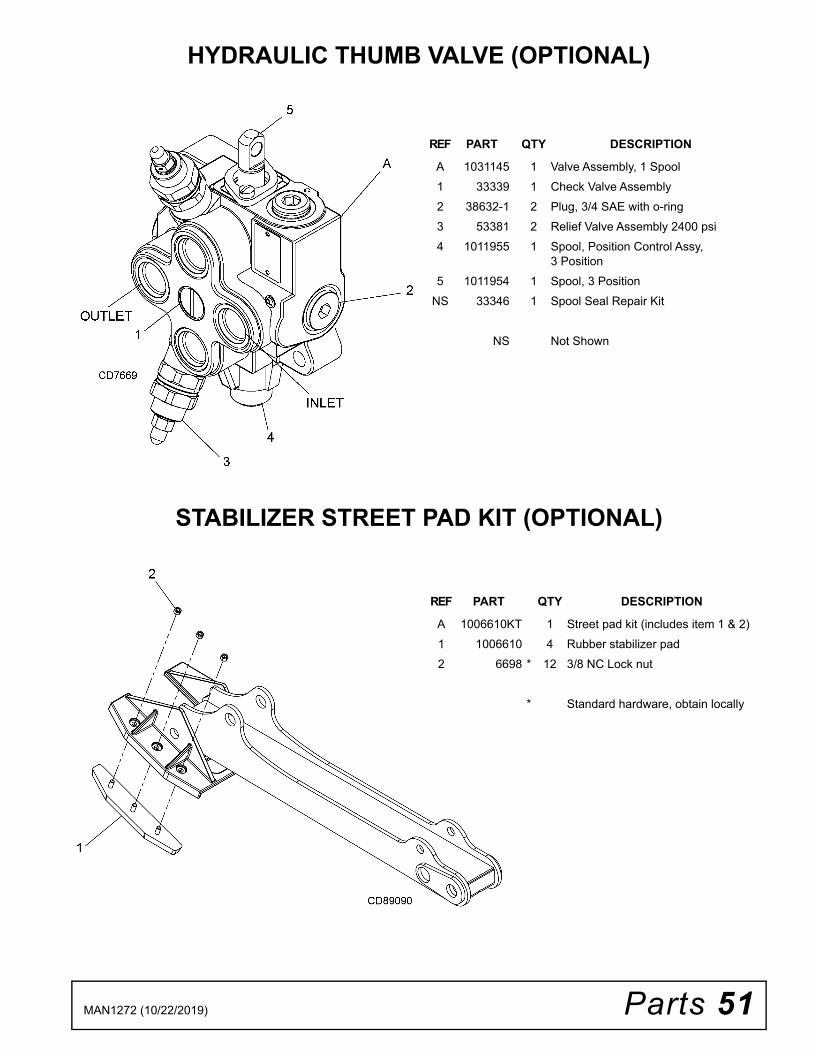
Parts 51MAN1272 (10/22/2019)
HYDRAULIC THUMB VALVE (OPTIONAL)
STABILIZER STREET PAD KIT (OPTIONAL)
REF PART QTY DESCRIPTION
A 1031145 1 Valve Assembly, 1 Spool1 33339 1 Check Valve Assembly2 38632-1 2 Plug, 3/4 SAE with o-ring3 53381 2 Relief Valve Assembly 2400 psi4 1011955 1 Spool, Position Control Assy,
3 Position5 1011954 1 Spool, 3 Position
NS 33346 1 Spool Seal Repair Kit
NS Not Shown
REF PART QTY DESCRIPTION
A 1006610KT 1 Street pad kit (includes item 1 & 2)1 1006610 4 Rubber stabilizer pad2 6698 * 12 3/8 NC Lock nut
* Standard hardware, obtain locally

52 Appendix Bolt Torque & Size Charts (Rev. 3/28/2007)
BOLT TORQUE CHARTAlways tighten hardware to these values unless a different torque value or tightening procedure is listed for a specific application.Fasteners must always be replaced with the same grade as specified in the manual parts list.Always use the proper tool for tightening hardware: SAE for SAE hardware and Metric for metric hardware.Make sure fastener threads are clean and you start thread engagement properly. All torque values are given to specifications used on hardware defined by SAE J1701 MAR 99 & J1701M JUL 96.
Diameter (Inches)
WrenchSize
MARKING ON HEAD
SAE 2 SAE 5 SAE 8
lbs-ft N-m lbs-ft N-m lbs-ft N-m1/4" 7/16" 6 8 10 13 14 18
5/16" 1/2" 12 17 19 26 27 373/8" 9/16" 23 31 35 47 49 67
7/16" 5/8" 36 48 55 75 78 1061/2" 3/4" 55 75 85 115 120 163
9/16" 13/16" 78 106 121 164 171 2325/8" 15/16" 110 149 170 230 240 3253/4" 1-1/8" 192 261 297 403 420 5697/8" 1-5/16" 306 416 474 642 669 9071" 1-1/2" 467 634 722 979 1020 1383
Diameter & Thread Pitch (Millimeters)
Wrench Size
COARSE THREAD FINE THREAD
Diameter & Thread Pitch (Millimeters)
MARKING ON HEAD MARKING ON HEAD
Metric 8.8 Metric 10.9 Metric 8.8 Metric 10.9
N-m lbs-ft N-m lbs-ft N-m lbs-ft N-m lbs-ft6 x 1.0 10 mm 8 6 11 8 8 6 11 8 6 x 1.0
8 x 1.25 13 mm 20 15 27 20 21 16 29 22 8 x 1.010 x 1.5 16 mm 39 29 54 40 41 30 57 42 10 x 1.25
12 x 1.75 18 mm 68 50 94 70 75 55 103 76 12 x 1.2514 x 2.0 21 mm 109 80 151 111 118 87 163 120 14 x 1.516 x 2.0 24 mm 169 125 234 173 181 133 250 184 16 x 1.518 x 2.5 27 mm 234 172 323 239 263 194 363 268 18 x 1.520 x 2.5 30 mm 330 244 457 337 367 270 507 374 20 x 1.522 x 2.5 34 mm 451 332 623 460 495 365 684 505 22 x 1.524 x 3.0 36 mm 571 421 790 583 623 459 861 635 24 x 2.030 x 3.0 46 mm 1175 867 1626 1199 1258 928 1740 1283 30 x 2.0
A
SAE SERIES TORQUE CHART
SAE Bolt Head Identification
SAE Grade 2(No Dashes)
SAE Grade 5(3 Radial Dashes)
SAE Grade 8(6 Radial Dashes)
A
METRIC SERIES TORQUE CHART
Metric Bolt Head Identification
8.8
MetricGrade 10.9
10.9
MetricGrade 8.8
A
A A
Typical Washer Installations Lock Washer
Flat Washer
8/9/00
Bolt

Appendix 53Bolt Torque & Size Charts (Rev. 3/28/2007)
BOLT SIZE CHARTNOTE: Chart shows bolt thread sizes and corresponding head (wrench) sizes for standard SAE and metric bolts.
ABBREVIATIONSAG .............................................................. AgricultureASABE.................... American Society of Agricultural &
Biological Engineers (formerly ASAE)ASAE ....... American Society of Agricultural EngineersATF ............................... Automatic Transmission FluidBSPP ............................ British Standard Pipe ParallelBSPTM ................British Standard Pipe Tapered MaleCV.................................................... Constant VelocityCCW .............................................. Counter-ClockwiseCW............................................................... ClockwiseF ...................................................................... FemaleFT .............................................................. Full ThreadGA..................................................................... GaugeGR (5, etc.) ........................................... Grade (5, etc.)HHCS ........................................Hex Head Cap ScrewHT........................................................... Heat-TreatedJIC .................Joint Industry Council 37°Degree FlareLH .................................................................Left HandLT........................................................................... Leftm......................................................................... Metermm................................................................MillimeterM.......................................................................... Male
MPa.........................................................Mega PascalN.......................................................................NewtonNC ......................................................National CoarseNF ...........................................................National FineNPSM.....................National Pipe Straight MechanicalNPT .......................................... National Pipe TaperedNPT SWF ......... National Pipe Tapered Swivel FemaleORBM .......................................... O-Ring Boss - MaleP...........................................................................PitchPBY ...................................................... Power-Beyondpsi..........................................Pounds per Square InchPTO..................................................... Power Take OffQD....................................................Quick DisconnectRH ..............................................................Right HandROPS ...........................Roll-Over Protective StructureRPM ........................................Revolutions Per MinuteRT........................................................................ RightSAE ..........................Society of Automotive EngineersUNC .....................................................Unified CoarseUNF...........................................................Unified FineUNS......................................................Unified Special
5/16 3/8 1/2 5/8 3/4 7/8SAE Bolt Thread Sizes
MM 25 50 75 100 125 150 175
IN 1 7
Metric Bolt Thread Sizes8MM 18MM14MM12MM10MM 16MM
2 3 4 5 6

54 Index MAN1272 (10/22/2019)
INDEXASSEMBLY
General Assembly Instructions 29Bucket Installation 30
Hydraulic Installation 30Open-Center Valve 31Pump Mounting Bracket Installation 31
Lifting Backhoe from Pallet 29Optional Equipment
Stabilizer Street Pad Installation 283-Point Mount Kit 31PTO Pump Kit 31Mechanical Thumb 31
DEALER CHECK LISTSDelivery Check List (Dealer’s Responsibility) 33Pre-Delivery Check List (Dealer’s Responsibility) 33
DEALER SERVICEControl Valve Linkage Adjustment 26Hydraulic Cylinder Repair
Swing Cylinders (Spanner Nut Cylinders)Assembly 28Disassembly 27
General Hydraulic Repair Information 24Hydraulic Valve Repair
Adjust System Relief Valve Pressure 25Pressure Settings on Port Relief Valves 25Replacing Port Relief Valves 25
GENERALAbbreviations 53Bolt Size Chart 53Bolt Torque Chart 52General Information 6Introduction 2Obtaining Replacement Manuals 2Specifications 4, 5Table of Contents 3Warranty
Product 56Replacement Parts 55
OPERATIONBackhoe Removal and Storage
3-Point Mount Removal 194-Point Sub-Frame Mount Removal 19Disconnect Tractor Hydraulics 19
Control Handle Operation 14Excavation
Dump and Return Cycle 16Filling Bucket 16Side Slope Trenching 16Starting Excavation 16Trenching 16
General Operation 14Position the Machine 14Pre-Operation Check List
(Owner’s Responsibility) 20Start and Stop Operation 14Swing Speed Control 15Thumb Operation 17
Hydraulic Thumb 17Transporting
Transport and Swing Lock Installation 18
OWNER SERVICECleaning
After Each Use 22Periodically or Before Extended Storage 22
Hydraulic Hoses and Fittings 21Lubrication 21Relief Valve 21
PARTSIndex to Parts Lists 35
SAFETYDelivery Check List (Dealer’s Responsibility) 33Pre-Delivery Check List (Dealer’s Responsibility) 33Pre-Operation Check List
(Owner’s Responsibility) 20Safety & Instructional Decals 11Safety Rules 7Safety Symbols Explained 2
TROUBLESHOOTINGTroubleshooting 24

F-8494 (Rev. 11/12/2018)
©2019 Woods Equipment Company. All rights reserved. Woods® and the Woods logo are trademarks of Woods Equipment Company. All othertrademarks, trade names, or service marks not owned by Woods Equipment Company that appear in this manual are the property of their respectivecompanies or mark holders. Specifications subject to change without notice.
WOODS®| A Blount International Brand2606 South Illinois Route 2 Post Office Box 1000Oregon, Illinois 61061 USA
800-319-6637 tel800-399-6637 faxwoodsequipment.com
WARRANTY(Replacement Parts For All Models Except Zero-Turn Mowers)
Woods Equipment Company (“WOODS”) warrants this product to be free from defect in material andworkmanship for a period of ninety (90) days from the date of delivery of the product to the original purchaserwith the exception of V-belts, which will be free of defect in material and workmanship for a period of 12 months.
Under no circumstances will this Warranty apply in the event that the product, in the good faith opinion ofWOODS, has been subjected to improper operation, improper maintenance, misuse, or an accident. This Warrantydoes not cover normal wear or tear, or normal maintenance items.
This Warranty is extended solely to the original purchaser of the product. Should the original purchaser sell orotherwise transfer this product to a third party, this Warranty does not transfer to the third party purchaser in anyway. There are no third party beneficiaries of this Warranty.
WOODS’ obligation under this Warranty is limited to, at WOODS’ option, the repair or replacement, free ofcharge, of the product if WOODS, in its sole discretion, deems it to be defective or in noncompliance with thisWarranty. The product must be returned to WOODS with proof of purchase within thirty (30) days aftersuch defect or noncompliance is discovered or should have been discovered, routed through the dealer anddistributor from whom the purchase was made, transportation charges prepaid. WOODS shall completesuch repair or replacement within a reasonable time after WOODS receives the product. THERE ARE NOOTHER REMEDIES UNDER THIS WARRANTY. THE REMEDY OF REPAIR OR REPLACEMENT IS THESOLE AND EXCLUSIVE REMEDY UNDER THIS WARRANTY.
THERE ARE NO WARRANTIES WHICH EXTEND BEYOND THE DESCRIPTION ON THE FACE OF THISWARRANTY. WOODS MAKES NO OTHER WARRANTY, EXPRESS OR IMPLIED, AND WOODSSPECIFICALLY DISCLAIMS ANY IMPLIED WARRANTY OF MERCHANTABILITY AND/OR ANYIMPLIED WARRANTY OF FITNESS FOR A PARTICULAR PURPOSE.
WOODS shall not be liable for any incidental or consequential losses, damages or expenses, arising directlyor indirectly from the product, whether such claim is based upon breach of contract, breach of warranty,negligence, strict liability in tort or any other legal theory. Without limiting the generality of the foregoing,Woods specifically disclaims any damages relating to (i) lost profits, business, revenues or goodwill; (ii) loss ofcrops; (iii) loss because of delay in harvesting; (iv) any expense or loss incurred for labor, supplies, substitutemachinery or rental; or (v) any other type of damage to property or economic loss.
This Warranty is subject to any existing conditions of supply which may directly affect WOODS’ ability to obtainmaterials or manufacture replacement parts.
No agent, representative, dealer, distributor, service person, salesperson, or employee of any company, includingwithout limitation, WOODS, its authorized dealers, distributors, and service centers, is authorized to alter, modify,or enlarge this Warranty.
Answers to any questions regarding warranty service and locations may be obtained by contacting:

F-3079 (Rev. 3/13/2020)
WOODS®| A Blount International Brand2606 South Illinois Route 2 Post Office Box 1000Oregon, Illinois 61061 USA
800-319-6637 tel800-399-6637 faxwoodsequipment.com
WARRANTYAll Models Except Zero-Turn Mowers
Please Enter Information Below and Save for Future Reference.
Date Purchased: ____________________________ From (Dealer): __________________________________________
Model Number: ____________________________ Serial Number: __________________________________________
Woods Equipment Company (“WOODS”) warrants this product to be free from defect in material and workmanship. Except as otherwise set forthbelow, the duration of this Warranty shall be for TWELVE (12) MONTHS COMMENCING ON THE DATE OF DELIVERY OF THEPRODUCT TO THE ORIGINAL PURCHASER.
All current model backhoes, loaders and mounts (except 3-pt. SAF-T-LOK mounts) are warranted for two (2) years from the date of delivery tothe original purchaser. The limited warranty covers any defects in the material and/or workmanship. Following the proper, recommendedinstallation by an authorized Woods Dealer and normal use of a Woods mounting and backhoe or loader, if a tractor incurs damage resulting fromthe attachment, Woods will cover the existing tractor warranty in the event the manufacturer voids its tractor warranty because of the attachment.Warranty does not cover any misuse or abusive conditions that could cause premature wear or damage to attachment or tractor.
The warranty periods for specific parts or conditions are listed below:
Under no circumstances will this Warranty apply in the event that the product, in the good faith opinion of WOODS, has been subjected toimproper operation, improper maintenance, misuse, or an accident. This Warranty does not apply in the event that the product has beenmaterially modified or repaired by someone other than WOODS, a WOODS authorized dealer or distributor, and/or a WOODS authorizedservice center. This Warranty does not cover normal wear or tear, or normal maintenance items. This Warranty also does not cover repairs madewith parts other than those obtainable through WOODS.This Warranty is extended solely to the original purchaser of the product. Should the original purchaser sell or otherwise transfer this product toa third party, this Warranty does not transfer to the third party purchaser in any way. There are no third party beneficiaries of this Warranty.WOODS makes no warranty, express or implied, with respect to engines, batteries, tires or other parts or accessories not manufactured byWOODS. Warranties for these items, if any, are provided separately by their respective manufacturers.WOODS’ obligation under this Warranty is limited to, at WOODS’ option, the repair or replacement, free of charge, of the product if WOODS,in its sole discretion, deems it to be defective or in noncompliance with this Warranty. The product must be returned to WOODS with proofof purchase within thirty (30) days after such defect or noncompliance is discovered or should have been discovered, routed through thedealer and distributor from whom the purchase was made, transportation charges prepaid. WOODS shall complete such repair orreplacement within a reasonable time after WOODS receives the product. THERE ARE NO OTHER REMEDIES UNDER THIS WARRANTY.THE REMEDY OF REPAIR OR REPLACEMENT IS THE SOLE AND EXCLUSIVE REMEDY UNDER THIS WARRANTY.THERE ARE NO WARRANTIES WHICH EXTEND BEYOND THE DESCRIPTION ON THE FACE OF THIS WARRANTY. WOODSMAKES NO OTHER WARRANTY, EXPRESS OR IMPLIED, AND WOODS SPECIFICALLY DISCLAIMS ANY IMPLIED WARRANTYOF MERCHANTABILITY AND/OR ANY IMPLIED WARRANTY OF FITNESS FOR A PARTICULAR PURPOSE.WOODS shall not be liable for any incidental or consequential losses, damages or expenses, arising directly or indirectly from theproduct, whether such claim is based upon breach of contract, breach of warranty, negligence, strict liability in tort or any other legaltheory. Without limiting the generality of the foregoing, Woods specifically disclaims any damages relating to (i) lost profits, business, revenuesor goodwill; (ii) loss of crops; (iii) loss because of delay in harvesting; (iv) any expense or loss incurred for labor, supplies, substitute machineryor rental; or (v) any other type of damage to property or economic loss.This Warranty is subject to any existing conditions of supply which may directly affect WOODS’ ability to obtain materials or manufacturereplacement parts.No agent, representative, dealer, distributor, serviceperson, salesperson, or employee of any company, including without limitation, WOODS, itsauthorized dealers, distributors, and service centers, is authorized to alter, modify, or enlarge this Warranty. Answers to any questions regardingwarranty service and locations may be obtained by contacting:
Part or Condition Warranted
Model NumberDuration (from date of delivery to the original
purchaser)
All units invoiced after 4/30/2012
Gearbox components
BB48.30, BB60.30, BB72.30, BB84.40, BB60.50, BB72.50, BB60.60, BB72.60, BB84.60, BB84.50,DS8.30, DS10.40, DS8.50, DSO8.50, DS10.50, DSO10.50, DBH5.31, DBH6.31
6 years
BW12, BW10.50, BW10.50Q, BW15.50, BW15.50Q, BW10.60, BW10.60Q, BW13.70, BW13.70Q,BW13.70QREV, BW15.60, BW15.60Q, BW10.70, BW10.70Q, BW15.70, BW15.70Q, BW20.50,BW20.50Q, BW20.60, BW20.60Q, BW20.70, BW20.70Q, BW20.51, BW20.51Q, BW20.61,BW20.61Q, BW20.71. BW20.71Q, BW13.71, BW13.71Q, BW13.71QREV
BW240X, BW240XHD, BW1620X, BW2400X
RD990X, PRD6000, PRD7200, PRD8400, S15CD, S20CD, S22CD, S25CD, S27CD, S30CD, TC/R74, TC/R68, TC/R60, TBW144, TBW180, TBW204, TSG50, S12ED, S15ED, S18ED, S20ED
FM60.20, FM72.20, TBW150C, RT/R42.30, RT/R48.30, RT/R60.40, RT/R72.40, RC3.5, RC4, RC5,RC6
3 years (1 year if used in rental or commercial applications)
Blade spindles RD990X, PRD6000, PRD7200, PRD8400, TBW144, TBW180, TBW204 3 years