BA_ QUICK_LA-M-STR_EN_V20
48
INSTRUCTIONS FOR USE LA, MAMMUT & STR KNURLING TOOLS
-
Upload
swarovski-optik -
Category
Documents
-
view
216 -
download
0
description
INSTRUCTIONS FOR USE lA, MAMMuT & STR KNuRlING TOOlS 5. Wear Parts.......................................................32 6. Knurling of Stepped Workpieces..................32 7. Knurl Cutters with Bevel................................34 8. Troubleshooting..............................................35 9. Dimensions and Pitches Available................37 10. Reference Values for Feeds and Cutting Speeds...........................................................39 Contents 1
Transcript of BA_ QUICK_LA-M-STR_EN_V20

INSTRUCTIONS FOR USElA, MAMMuT & STR KNuRlING TOOlS


Contents
CONTENTS
1. General .............................................................. 2 1.1 Introduction................................................ 2 1.2 Tool Construction....................................... 3
2. LA-Tool .............................................................. 5 2.1 Technical Data........................................... 5 2.2 Overview: Main Components..................... 6 2.3 Tool Adjustment LA/KF .............................. 7 2.4 Tool Adjustment LA/FL............................. 11
3. Mammut-Tool .................................................. 15 3.1 Technical Data......................................... 15 3.2 Overview: Main Components................... 16 3.3 Tool Adjustment M/KF.............................. 17 3.4 Tool Adjustment M/FL .............................. 21
4. STR-Tool.......................................................... 25 4.1 Technical Data......................................... 25 4.2 Overview: Main Components................... 27 4.3 Tool Adjustment STR ............................... 28
5. Wear Parts .......................................................32 6. Knurling of Stepped Workpieces ..................32 7. Knurl Cutters with Bevel ................................34 8. Troubleshooting..............................................35 9. Dimensions and Pitches Available................37 10. Reference Values for Feeds and Cutting
Speeds ...........................................................39
1
General Introduction
1. General 1.1 Introduction
Please read through the Instructions for Use carefully before using the QUICK knurl cutting tools!
The instructions have been written for operators with qualified training in the field of machining and cutting.
Compliance with the Instructions for Use increases reliability in use,
increases the service life of the tools,
and prevents downtimes.
We reserve the right to make alterations to the technical details of the tools by comparison with the information and illustrations contained in these Instructions for Use. Swarovski Optik KG
Symbols in these instructions
ATTENTION:
This Symbol warns that operating procedures carried out without paying attention to the measures specified may lead to damage to the tool and/or the machine tool.
NOTE:
This Symbol refers to further information and provides additional information for using the Quick knurling tools.
Text markups:
This symbol identifies lists
This symbol identifies an action sequence
2
General Tool Construction
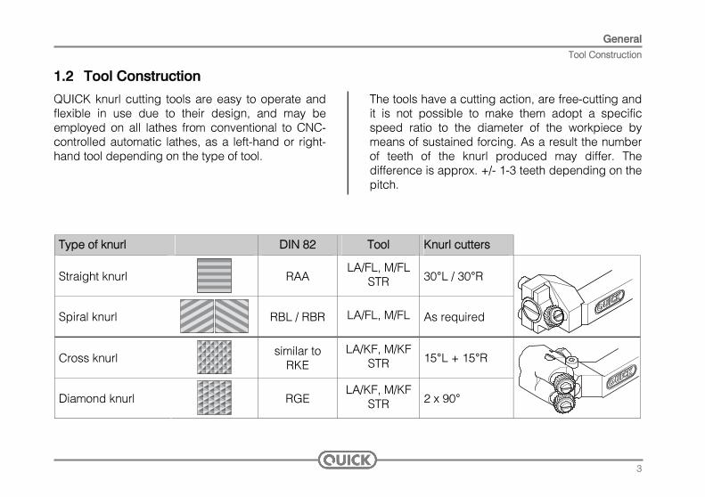
1.2 Tool Construction
QUICK knurl cutting tools are easy to operate and flexible in use due to their design, and may be employed on all lathes from conventional to CNC-controlled automatic lathes, as a left-hand or right-hand tool depending on the type of tool.
The tools have a cutting action, are free-cutting and it is not possible to make them adopt a specific speed ratio to the diameter of the workpiece by means of sustained forcing. As a result the number of teeth of the knurl produced may differ. The difference is approx. +/- 1-3 teeth depending on the pitch.
Type of knurl DIN 82 Tool Knurl cutters
Straight knurl
RAA LA/FL, M/FL
STR 30°L / 30°R
Spiral knurl
RBL / RBR LA/FL, M/FL As required
Cross knurl
similar to RKE
LA/KF, M/KFSTR 15°L + 15°R
Diamond knurl
RGE LA/KF, M/KF
STR 2 x 90°
3

General Tool Construction
Tool definition LA-model range LA knurl cutting tools are available in both right-hand and left-hand versions. Use only tools marked R (right-hand version) in holders for right-hand cutting tools and tools marked L (left-hand version) in holders for left-hand cutting tools. left right left right
Tool definition Mammut-model range Knurl cutting tools of the Mammut range are only available in a right-hand version.
Perfect results may be achieved with:
Correct adjustment
Closely following the instructions regarding the start of the knurling process
Appropriate feed and cutting speed
Selection of the correct tool size. QUICK knurl cutter tools with large dimensioned knurl cutters, e.g. Ø 42 mm instead of Ø 32, have a longer service life
NOTE: It is imperative to ensure an abundant supply of coolant or cutting oil directly onto the knurl cutters to ensure perfect cooling and lubrication of the knurl cutters.
4

LA-Tool Technical Data
5
2. LA-Tool 2.1 Technical Data
LA/KF Types of knurl Cross and diamond Working range Ø 1.5-12 mm Shank dimension 8x8, 10x10 or 12x12 mm / L or R Knurl cutters Ø 8.9 mm
Cross 1 x 15°L and 1 x 15°R Diamond 2 x 90°
Pitches see page 37 Weight 0.15 kg
LA/FL Types of knurl Straight and spiral Working range Ø 1.5-12 mm Shank dimension 8x8, 10x10 or 12x12 mm / L or R Knurl cutters Ø 8.9 mm
Straight 1 x 30°L / 30°R Spiral as required
Pitches see page 37 Weight 0.13 kg
(figure — right-hand tool)
20
8/10
/1222
105
83
28
108
88
2020
8/10
/1220

LA-Tool Overview: Main Components
6
2.2 Overview: Main Components
(figure — right-hand tool)
Pos. Designation
1 Tool head 1.1 Cutter holder 2 Screw 3 Washer 4 Knurl cutter 5 Bushing 6 Scale ring (diameter adjustment) 7 Index point 8 Clamping screw 9 Shank
10 Adjusting screw — tool correction
A
A
LA/KF
LA/FL
A
A
2
2
10
10
7 89
9
6
3
3
4
4
5
5 1
1
1
1.1
1.1
1.1

LA-Tool Tool Adjustment LA/KF
2.3 Tool Adjustment LA/KF
Preliminary work:
Clamp workpiece and turn Maximum out-of-roundness 0.03 mm
Step 1: Cutter selection Cross knurl:
1x 15° left-hand spiral toothed knurl cutter on cutter holder „L“ 1x 15° right-hand spiral toothed knurl cutter on
cutter holder „R“ Diamond knurl:
2x 90° toothed knurl cutters
L
LA/KF R
R
Step 2: Install knurl cutters
Clean the contact surface of bushing 5 and cutter holder 1.1.
Coat bushing 5 and the face ends as well as the hole of knurl cutter 4 with a little Molykote G paste
With knurl cutter 4 and washer 3 pushed on, insert bushing 5 into the cutter holder
Screw in screw 2 and only tighten enough to allow knurl cutter 4 to rotate free of play
2 3 4 5 1.1
7

LA-Tool Tool Adjustment LA/KF
Step 3: Set diameter
Measure off workpiece diameter
Unscrew clamping screw 8
Turn scale ring 6 until the required diameter aligns with index point 7
Clamp clamping screw 8
7 86
Step 4: Clamp tool in tool holder
Step 5: Pre-adjust turning centre
The tool must be centered when used on conventional lathes.
NOTE: This adjustment does not apply when used on CNC machines as the tools are already centered.
8

LA-Tool Tool Adjustment LA/KF
Step 6: Re-align turning centre
Carefully bring into contact with the workpiece Both cutters must be in contact simultaneously.
Precision adjustment is carried out using adjusting screw 10
When adjusting by way of screw 10a, first loosen screw 10b and vice versa
Tighten the opposing screw again hand-tight when adjustment is complete
10a
10b Step 7: Adjust cutter The ideal position of the knurling cutters is when they lie parallel on the workpiece and still cut very slightly, i.e. the cutting edge of the cutters can be pressed in somewhat deeper (approx. 1-2°). In the case of materials which are hard to machine, the knurling cutters may be inclined up to max. 3-4°.
Sequence:
Unscrew clamping screw 8 Adjust scale ring 6 slightly towards the next
smaller diameter until the correct cutter setting is reached
Tighten clamping screw 8
86
9

LA-Tool Tool Adjustment LA/KF
10
ATTENTION: Under no circumstances knurl with longitudinal feed into the face edge of the workpiece. Starting the knurl within the workpiece can be done only in certain circumstances.
NOTE: Note that the protective bevel at the beginning of the workpiece may not be applied until knurling is complete.
The coarser the pitch, the smaller the feed. Feed and cutting speed have no effect on the knurl pitch.
NOTE: If the knurl is not accurate or is one-sided, then the knurling process may be repeated after correcting the tool.
Step 9: Knurling
The knurling depth corresponds to the pitch of the knurling cutter being used, e.g. 1.0 mm pitch requires 1.0 mm infeed with reference to the diameter. The depth is measured from the knurling cutter's point of contact with the workpiece.
The start of the knurl should be in a width no greater than 1,0 mm. With this width now move the tool to the full depth without interruption. The feed on infeeding should be approx. 0.05-0.1 mm.
Step 8: Start of knurl
After an idle time of 2-3 seconds, the workpiece is knurled by using the longitudinal feed. The surface deformation of the workpiece cannot be determined exactly as this is different from material to material. The knurling depth, however, should be sufficient to ensure that the knurl is only just sharp.
max 1,0 mm

LA-Tool Tool Adjustment LA/FL
2.4 Tool Adjustment LA/FL
Preliminary:
Clamp workpiece and turn Maximum out-of-roundness 0.03 mm
Step 1: Cutter selection Straight knurl – right-hand tool: 1x 30° right-hand spiral toothed knurl cutter Straight knurl - left-hand tool: 1x 30° left-hand spiral toothed knurl cutter
NOTE: Right-hand tool requires the workpiece to rotate in a clockwise direction. Left-hand tool requires the workpiece to rotate in an anti-clockwise direction.
Spiral knurl:
Knurl cutters are to be mounted with 15°, 30° or 90° spirals depending on the pitch of the spiral desired on the workpiece. It is advisable due to the large number of possible variations to consult your dealer or the manufacturer.
Step 2: Install knurl cutters
Clean the contact surface of bushing 5 and cutter holder 1.1.
Coat bushing 5 and the face ends as well as the hole of knurl cutter 4 with a little Molykote G paste
With knurl cutter 4 and washer 3 pushed on, insert bushing 5 into the cutter holder
Screw in screw 2 and only tighten enough to allow knurl cutter 4 to rotate free of play
3 4 5 1.12
11

LA-Tool Tool Adjustment LA/FL
Step 3: Clamp tool in tool holder
Step 4: Adjust turning centre
The tool must be centered when used on conventional lathes.
NOTE: This adjustment does not apply when used on CNC machines as the tools are already centered.
Step 5: Adjust cutter
The ideal position of the knurling cutters is when they lie parallel on the workpiece and still cut very slightly, i.e. the cutting edge of the cutters can be pressed in somewhat deeper (approx. 1-2°). In the case of materials which are hard to machine, the knurling cutters may be inclined up to max. 3-4°.
Sequence:
Correction is achieved by turning the tool slightly in the tool holder
12

LA-Tool Tool Adjustment LA/FL
Step 6: Start of knurl
The start of the knurl should be in a width no greater than 1,0 mm. With this width now move the tool to the full depth without interruption. The feed on infeeding should be approx. 0.05-0.1 mm. The knurling depth corresponds to the pitch of the knurling cutter being used, e.g. 1.0 mm pitch requires 1.0 mm infeed with reference to the diameter. The depth is measured from the knurling cutter's point of contact with the workpiece. After an idle time of 2-3 seconds, the workpiece is knurled by using the longitudinal feed. The surface deformation of the workpiece cannot be determined exactly as this is different from material to material. The knurling depth, however, should be sufficient to ensure that the knurl is only just sharp.
max 1,0 mm
ATTENTION: Under no circumstances knurl with longitudinal feed into the face edge of the workpiece. Starting the knurl within the workpiece can be done only in certain circumstances.
NOTE: Note that the protective bevel at the beginning of the workpiece may not be applied until knurling is complete.
The coarser the pitch, the smaller the feed. Feed and cutting speed have no effect on the knurl pitch.
13
LA-Tool Tool Adjustment LA/FL
14
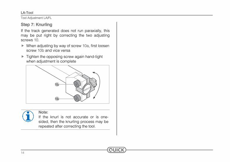
If the track generated does not run paraxially, this may be put right by correcting the two adjusting screws 10.
Step 7: Knurling
When adjusting by way of screw 10a, first loosen screw 10b and vice versa
Tighten the opposing screw again hand-tight when adjustment is complete
10a
10b
Note: If the knurl is not accurate or is one-sided, then the knurling process may be repeated after correcting the tool.

Mammut-Tool Technical Data
3. Mammut-Tool 3.1 Technical Data
MI-MII/KF (Dimensions in brackets MII/KF) Types of knurl Cross and diamond Working range Ø 20-1000 mm (30-3000 mm) Shank dimension 45x40 mm (90x60 mm) Knurl cutters Ø 32 mm (42 mm)
Cross 1 x 15°L and 1 x 15°R Diamond 2 x 90°
Pitches see page 37 Weight 6 kg (18 kg)
M/FL Types of knurl Straight and spiral Working range Ø 20-3000 mm Shank dimension 35x27 mm Knurl cutters Ø 42 mm
Straight 1 x 30°R Spiral as required
Pitches see page 37 Weight 1.6 kg
280 (445)
110
(165
)79
(117
)
45 (6
8)40
(60)
160 (275)
104
55
195
150
120
5771
2735
15

Mammut-Tool Overview: Main Components
16
3.2 Overview: Main Components
Pos. Designation
1 Tool head 2 Screw 3 Washer 4 Knurl cutter 5 Bushing 6 Scale ring (diameter adjustment) 7 Index point 8 Clamping screws 9 Shank 10 Adjusting screw — tool correction 11 Locking screw / Clamping screw (M/FL) 12 Hexagonal nut A
80
12020
0
A
A
M/KF
M/FL
A
2 3 4 5 1 9 10 1111 7 6 8
2 3 4 5 1 9 1110
8
12 10 1

Mammut-Tool Tool Adjustment M/KF
3.3 Tool Adjustment M/KF
Preliminary work:
Clamp workpiece and turn Maximum out-of-roundness: 0.05 mm
Step 1: Cutter selection Cross knurl:
1x 15° left-hand spiral toothed knurl cutter on the cutter holder closest to scale ring 6 1x 15° right-hand spiral toothed knurl cutter on the
opposing cutter holder Diamond knurl:
2x 90° toothed knurl cutters
6
Step 2: Install knurl cutters
Clean the contact surface of bushing 5 and cutter holder 1.1.
Coat bushing 5 and the face ends as well as the hole of knurl cutter 4 with a little Molykote G paste
With knurl cutter 4 and washer 3 pushed on, insert bushing 5 into the cutter holder
Screw in screw 2 and only tighten enough to allow knurl cutter 4 to rotate free of play
2 3 4 5 1.1
17

Mammut-Tool Tool Adjustment M/KF
Step 3: Set diameter
Measure off workpiece diameter
Unscrew clamping screw 8
Turn scale ring 6 until the required diameter aligns with index point 7
Clamp clamping screw 8
80
12020
0
8
8
7
6
Step 4: Clamp tool in tool holder
Step 5: Pre-adjust turning centre
Clamp tool in carriage so that holder shank is perpendicular to rotary axis
Align centering device C at tip height on the swivel axis
80
12020
0
C
18
Mammut-Tool Tool Adjustment M/KF
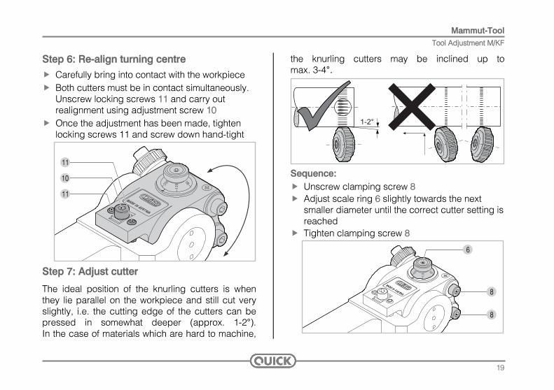
Step 6: Re-align turning centre
Carefully bring into contact with the workpiece Both cutters must be in contact simultaneously.
Unscrew locking screws 11 and carry out realignment using adjustment screw 10
Once the adjustment has been made, tighten locking screws 11 and screw down hand-tight
80
12020
0
11
10
11
Step 7: Adjust cutter
The ideal position of the knurling cutters is when they lie parallel on the workpiece and still cut very slightly, i.e. the cutting edge of the cutters can be pressed in somewhat deeper (approx. 1-2°). In the case of materials which are hard to machine,
the knurling cutters may be inclined up to max. 3-4°.
Sequence: Unscrew clamping screw 8 Adjust scale ring 6 slightly towards the next
smaller diameter until the correct cutter setting is reached
Tighten clamping screw 8
80
12020
0
8
8
6
19

Mammut-Tool Tool Adjustment M/KF
20
ATTENTION: Under no circumstances knurl with longitudinal feed into the face edge of the workpiece. Starting the knurl within the workpiece can be done only in certain circumstances.
NOTE: Note that the protective bevel at the beginning of the workpiece may not be applied until knurling is complete.
The coarser the pitch, the smaller the feed. Feed and cutting speed have no effect on the knurl pitch.
NOTE: If the knurl is not accurate or is one-sided, then the knurling process may be repeated after correcting the tool.
Step 9: Knurling
The knurling depth corresponds to the pitch of the knurling cutter being used, e.g. 1.0 mm pitch requires 1.0 mm infeed with reference to the diameter. The depth is measured from the knurling cutter's point of contact with the workpiece.
The start of the knurl should be in a width no greater than 3.0 mm. With this width now move the tool to the full depth without interruption. The feed on infeeding should be approx. 0.05-0.1 mm.
Step 8: Start of knurl
After an idle time of 2-3 seconds, the workpiece is knurled by using the longitudinal feed. The surface deformation of the workpiece cannot be determined exactly as this is different from material to material. The knurling depth, however, should be sufficient to ensure that the knurl is only just sharp.
max 3,0 mm
Mammut-Tool Tool Adjustment M/FL
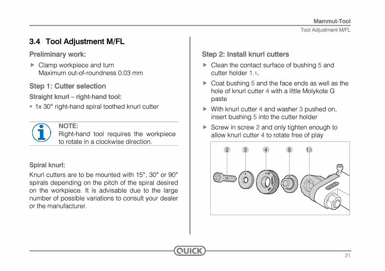
3.4 Tool Adjustment M/FL
Preliminary work:
Clamp workpiece and turn Maximum out-of-roundness 0.03 mm
Step 1: Cutter selection Straight knurl – right-hand tool:
1x 30° right-hand spiral toothed knurl cutter
NOTE: Right-hand tool requires the workpiece to rotate in a clockwise direction.
Spiral knurl:
Knurl cutters are to be mounted with 15°, 30° or 90° spirals depending on the pitch of the spiral desired on the workpiece. It is advisable due to the large number of possible variations to consult your dealer or the manufacturer.
Step 2: Install knurl cutters
Clean the contact surface of bushing 5 and cutter holder 1.1.
Coat bushing 5 and the face ends as well as the hole of knurl cutter 4 with a little Molykote G paste
With knurl cutter 4 and washer 3 pushed on, insert bushing 5 into the cutter holder
Screw in screw 2 and only tighten enough to allow knurl cutter 4 to rotate free of play
2 3 4 5 1.1
21

Mammut-Tool Tool Adjustment M/FL
Step 3: Clamp tool in tool holder
Step 4: Adjust turning centre
Clamp tool in carriage so that holder shank is perpendicular to rotary axis
Align centering device C at tip height on the swivel axis
C
Step 5: Adjust cutter
The ideal position of the knurling cutters is when they lie parallel on the workpiece and still cut very slightly, i.e. the cutting edge of the cutters can be pressed in somewhat deeper (approx. 1-2°). In the case of materials which are hard to machine, the knurling cutters may be inclined up to max. 3-4°.
Sequence:
Correction is achieved by turning the tool slightly in the tool holder
22

Mammut-Tool Tool Adjustment M/FL
Step 6: Start of knurl
The start of the knurl should be in a width no greater than 3.0 mm. With this width now move the tool to the full depth without interruption. The feed on infeeding should be approx. 0.05-0.1 mm. The knurling depth corresponds to the pitch of the knurling cutter being used, e.g. 1.0 mm pitch requires 1.0 mm infeed with reference to the diameter. The depth is measured from the knurling cutter's point of contact with the workpiece. After an idle time of 2-3 seconds, the workpiece is knurled by using the longitudinal feed. The surface deformation of the workpiece cannot be determined exactly as this is different from material to material. The knurling depth, however, should be sufficient to ensure that the knurl is only just sharp.
max 3,0 mm
ATTENTION: Under no circumstances knurl with longitudinal feed into the face edge of the workpiece. Starting the knurl within the workpiece can be done only in certain circumstances.
NOTE: Note that the protective bevel at the beginning of the workpiece may not be applied until knurling is complete.
The coarser the pitch, the smaller the feed. Feed and cutting speed have no effect on the knurl pitch.
23

Mammut-Tool Tool Adjustment M/FL
24
NOTE: If the knurl is not accurate or is one-sided, then the knurling process may be repeated after correcting the tool.
If the track generated does not run paraxially, this may be put right by correcting the two adjusting screws 10.
Step 7: Knurling
Unscrew hexagonal nut 12
Unscrew clamping screw 11 and subsequently tighten lightly again to achieve a tolerance-free adjustment
When adjusting by way of screw 10a, first loosen screw 10b and vice versa
Tighten the opposing screw again hand-tight when adjustment is complete
Tighten clamping screw 11 and hexagonal nut 12
11
10b
10a
12

STR-Tool Technical Data
4. STR-Tool 4.1 Technical Data
STR/A-STR/B (Dimensions in brackets STR/B) Types of knurl Cross, diamond and straight Working range Ø 2.8 (core Ø)-25 mm (Ø 5-55 mm) Shank diameter see page 26 Knurl cutters Ø 14.5 mm (21.5 mm)
Cross 2 x 15°R and 1 x 15°L Diamond 3 x 90°
Straight 2 x 30°L and 1 x 30°R Pitches see page 37 Weight 0.5 kg (2.0 kg) Bore of knurling head (A)
20 mm (35 mm)
Bore length (B) 25.5 mm (37 mm) Knurling head Ø (C) 54 mm (95 mm) Length of knurling head (D)
37 mm (52 mm)
Length of cutter holder (E)
15 mm (30 mm)
B
A
C
ED
25

STR-Tool Technical Data
Shanks STR/A Clamping Ø (F) Clamping length (G) Bore Ø (H)
15 mm 50 mm 9 mm 20 mm 50 mm 10 mm 25 mm 50 mm 15 mm ¾“ 50 mm 9 mm ⅝“ 50 mm 9 mm 1“ 50 mm 15 mm MK2 69 mm 8,5 mm
F
H
G
Shanks STR/B Clamping Ø (F) Clamping length (G) Bore Ø (H)
20 mm 70 mm 10 mm 25 mm 70 mm 15 mm 30 mm 70 mm 18 mm 1“ 70 mm 15 mm 1 ¼“ 70 mm 18 mm 1 ½“ 70 mm 25 mm MK3 86 mm 10 mm
26
STR-Tool Overview: Main Components
27
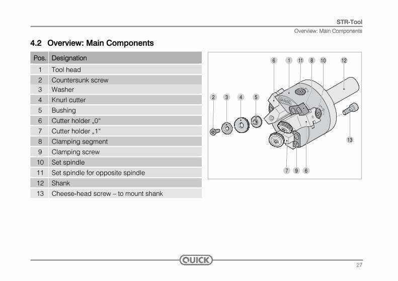
4.2 Overview: Main Components
Pos. Designation
1 Tool head 2 Countersunk screw 3 Washer 4 Knurl cutter 5 Bushing 6 Cutter holder „0“ 7 Cutter holder „1“ 8 Clamping segment 9 Clamping screw 10 Set spindle 11 Set spindle for opposite spindle 12 Shank 13 Cheese-head screw — to mount shank
2 3 4 5
1 11 8 10 12
7
13
9 6
6

STR-Tool Tool Adjustment STR
4.3 Tool Adjustment STR
Preliminary work:
Clamp workpiece and turn Maximum out-of-roundness 0.03 mm
Turn a shoulder or, with smaller pitches up to 0.6 mm, a 30° bevel
30°
1,5xT1,5xT
ø-0,
5xT
T = pitch
NOTE: This chamfering means that the knurl cutters only have to remove a small amount of material at the beginning and can therefore centre themselves better. The shoulder is particularly important for flat knurls.
Step 1: Install shank
Attach shank 12 to tool head 1 using three hexagonal socket head screws 13
1312
1
13
28

STR-Tool Tool Adjustment STR
Step 2: Cutter selection Straight knurl:
2x 30°L knurl cutter on cutter holder„0“ 1x 30°R knurl cutter on cutter holder„1“ Cross knurl:
2x 15°R knurl cutter on cutter holder„0“ 1x 15°L knurl cutter on cutter holder„1“ Diamond knurl:
2x 90° knurl cutter on cutter holder„0“ 1x 90° knurl cutter on cutter holder„1“
0
0
1
Step 3: Install knurl cutters
Clean the contact surface of bushing 5 and cutter holder 1.1.
Coat bushing 5 and the face ends as well as the hole of knurl cutter 4 with a little Molykote G paste
With knurl cutter 4 and washer 3 pushed on, insert bushing 5 into the cutter holder
Screw in countersunk screw 2 and only tighten enough to allow knurl cutter 4 to rotate free of play
2 3 4 5
1.1
Step 4: Clamp tool in tool holder
29

STR-Tool Tool Adjustment STR
Step 5: Set diameter Version with infeed
Unscrew six clamping screws 9 on the clamping jaws
Open cutter holder 6 by means of positioning spindles 10 and cutter holder 7 via central positioning spindle 11 enough for the tool to be positioned above the workpiece
Position the tool above the workpiece and lightly tighten clamping screws 9
Adjust positioning spindles 10/11 individually until the knurl cutters just touch the workpiece lightly
910 10114 6
7 6
Retract the knurl cutting tool for subsequent infeed
The infeed depth is adjusted in the direction of the arrow using the indexing on positioning spindles 10/11 The number of index pitches to be adjusted is calculated as follows: Cutter pitch (T)/2 x 7, results in an adjustment by 3.5 index pitches for a cutter pitch of 1 mm for example
Adjust the cutter holders individually by the value calculated and then screw down clamping screws 9 hand-tight
910 1011
30

STR-Tool Tool Adjustment STR
Version - Adjustment to core diameter
Turn workpiece to knurl core diameter DK
Unscrew six clamping screws 9 on the clamping jaws
Open cutter holder 6 by means of positioning spindles 10 and cutter holder 7 via central positioning spindle 11 enough for the tool to be positioned above the workpiece
Position tool above shoulder and lightly tighten clamping screws 9
D K
910 10114 6
7 6
Adjust positioning spindles 10/11 individually until the knurl cutters just touch the workpiece lightly on core diameter DK
Retract knurl milling tool
Screw down clamping screws 9 hand-tight
Step 6: Start of knurl
Feed in quickly to the shoulder and only very little into the full material using a feed rate of 0.1- 0.15 mm/rev
After an idle time of 2-3 seconds, the workpiece is knurled by using the longitudinal feed
After completing the knurl, retract the tool in rapid traverse
The coarser the pitch, the smaller the feed. Feed and cutting speed have no effect on the knurl pitch.
31

Wear Parts
32
Tool Adjustment STR
It must be noted that with all QUICK knurl cutting tools it is not possible to knurl right up to a shoulder due to the inclined position of the knurl cutters. Please refer to the table for dimensions.
6. Knurling of Stepped Workpieces
b
a
The fixing elements for the knurl cutters of the QUICK knurl cutting tools are wear parts and must be replaced frequently.
1a 1b 1c
2a 2a 2b
3 33
5. Wear Parts
Pos. Designation Typ 1a Slot screw LA 1b Cheese-head screw M/KF, M/FL 1c Countersunk screw STR 2a Washer LA, M/KF, M/FL 2b Washer STR 3 Bushing

Knurling of Stepped Workpieces
Distance b corresponds to the Ø of the knurl cutters
Ø 8.9 Ø 14.5 Ø 21.5 Ø 32 Ø 42
a b b b b b 1 1.0 1.3 2 1.5 1.8 2 2.5 1.8 2.6 2.5 3.0 3 3.0 2.2 3.0 3.1 4.3
4 2.6 3.8 3.8 5.7
5 2.8 4.5 4.5 6.7
6 3.1 4.7 5.1 7.5
7 5 6.2 8.1
8 5.3 7.6 8.6
9 5.3 9.4 9.1
10 9.8 9.5
11 10.4 9.8
12 10.6 10.1
13 10.8 12.2
14 11.1 13.1
15 13.6
16 14.1
18 14.6
33

Knurl Cutters with Bevel
7. Knurl Cutters with Bevel A knurl cutter's teeth may break off when knurling "hard" materials. It is possible to increase the knurl cutter's service life by cutting a 45° bevel. This is only applicable for the KF and STR models. The drawing beside shows which knurl cutter may have bevel. Ø 32 mm and Ø 42 mm cutters are already produced with bevel.
0,5 x t
t45°
Arrangement for KF- tools
Arrangement for STR- tools
34

Troubleshooting
8. Troubleshooting KF-Tools Knurl trailing spirally Look at start of knurl Look at knurling depth Tool tilted sideways -> check position Clearance of tool too positive or too negative
Overlapping of the knurl (double knurl) Incorrect adjustment of diameter Approach to knurl depth too slow as a result of which too
little guidance of knurl cutters in track Look at start of knurl
Teeth of knurl cutters knocked off Bevel knurl cutters with hard materials Knurl cutter has been overloaded too much feed, cutting
depth too great Incorrect adjustment of diameter Fixing screws of knurl cutters loose Look at adjustment of cutters
Unevenly deep knurl track Re-align position of head using spindle
Seizing of knurl cutters on bushing (see FL)
FL-Tools Knurl trailing spirally Correct position of head using precision adjustment
screws Look at start of knurl Look at knurling depth Tool tilted sideways -> check position Clearance of tool too positive or too negative
Overlapping of the knurl (double knurl) Approach to knurl depth too slow as a result of which too
little guidance of knurl cutters in track Look at start of knurl
Teeth of knurl cutters knocked off Knurl cutter has been overloaded feed too great, cutting
depth too great Fixing screws of knurl cutters loose Look at direction of rotation Look at adjustment of cutters
Seizing of knurl cutters on bushing Reduce cutting speed Use Molykote paste Coolant jet directly onto the knurl cutter
35

Troubleshooting
STR-Tools Knurl does not come up to the requirements Are the knurl cutters on the right holder? Tool head and workpiece axis are not aligned All three knurl cutters do not have the same cutting depth Knurl trailing spirally Look at start of knurl (turn a centering stepp) Look at knurling depth Tool tilted sideways -> check position Overlapping of the knurl (double knurl) Approach to knurl depth too slow as a result of which too
little guidance of knurl cutters in track Look at start of knurl Incorrect adjustment of diameter
Teeth of knurl cutters knocked off Bevel knurl cutters with hard materials Knurl cutter has been overloaded too much feed, cutting
depth too great Fixing screws of knurl cutters loose Incorrect adjustment of diameter
Seizing of knurl cutters on bushing Reduce cutting speed Use Molykote paste Coolant jet directly onto the knurl cutter
36
Dimensions and Pitches Available
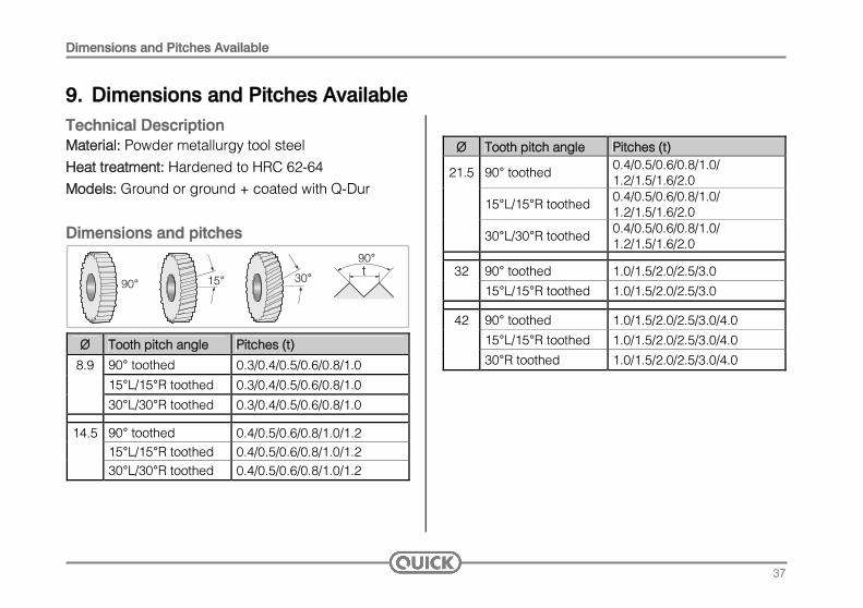
9. Dimensions and Pitches Available Technical Description Material: Powder metallurgy tool steel Heat treatment: Hardened to HRC 62-64 Models: Ground or ground + coated with Q-Dur
Dimensions and pitches 90°
t90°
30°15°
Ø Tooth pitch angle Pitches (t)
8.9 90° toothed 0.3/0.4/0.5/0.6/0.8/1.0
15°L/15°R toothed 0.3/0.4/0.5/0.6/0.8/1.0
30°L/30°R toothed 0.3/0.4/0.5/0.6/0.8/1.0
14.5 90° toothed 0.4/0.5/0.6/0.8/1.0/1.2 15°L/15°R toothed 0.4/0.5/0.6/0.8/1.0/1.2 30°L/30°R toothed 0.4/0.5/0.6/0.8/1.0/1.2
Ø Tooth pitch angle Pitches (t)
21.5 90° toothed 0.4/0.5/0.6/0.8/1.0/ 1.2/1.5/1.6/2.0
15°L/15°R toothed 0.4/0.5/0.6/0.8/1.0/ 1.2/1.5/1.6/2.0
30°L/30°R toothed 0.4/0.5/0.6/0.8/1.0/ 1.2/1.5/1.6/2.0
32 90° toothed 1.0/1.5/2.0/2.5/3.0
15°L/15°R toothed 1.0/1.5/2.0/2.5/3.0
42 90° toothed 1.0/1.5/2.0/2.5/3.0/4.0
15°L/15°R toothed 1.0/1.5/2.0/2.5/3.0/4.0
30°R toothed 1.0/1.5/2.0/2.5/3.0/4.0
37

Dimensions and Pitches Available
Order numbers and designation
Ident. no. Ø A Ø B C 270 8.9 4 2.5 271 14.5 5 3.0
272 21.5 8 5.0
273 32 14 8.0
274 42 18 12.0
Pos. Description
1 Production date MM/YY 2 Tooth pitch angle 3 Tooth pitch direction R (right) L (left) 4 Tooth pitch 5 Material 6 Tooth tip angle 7 Production process G (ground) / M (milled) 8 Coated with QDUR / TiCN / TIN
38

Reference Values for Feeds and Cutting Speeds
10. Reference Values for Feeds and Cutting Speeds Workpiece
Ø 1.5-12 Workpiece
Ø 12-40 Workpiece
Ø 40-250 Workpiece Ø over 250
Material Cutter Ø V m/min
s mm/rev
V m/min
s mm/rev
V m/min
s mm/rev
V m/min
s mm/rev
8.9 35 0.05-0.08
14.5 45 0.07-0.09 40 0.07-0.09
21.5 60 0.07-0.14 60 0.07-0.15 55 0.07-0.15
32 90 0.10-0.20 85 0.10-0.20 80 0.10-0.20
Steel up to 600 N/mm²
42 100 0.10-0.30 95 0.10-0.20
8.9 25 0.04-0.07
14.5 35 0.06-0.08 30 0.06-0.08
21.5 50 0.06-0.12 45 0.06-0.12 40 0.06-0.12
32 70 0.08-0.16 65 0.08-0.16
Steel up to 900 N/mm²
42 80 0.09-0.25 60 0.08-0.16
8.9 22 0.04-0.06
14.5 30 0.06-0.08 28 0.06-0.08
21.5 40 0.06-0.12 35 0.06-0.12 32 0.06-0.12
32 45 0.08-0.16 42 0.08-0.16 40 0.08-0.16
Stainless steels
42 55 0.09-0.25 50 0.09-0.25
39

Reference Values for Feeds and Cutting Speeds
Workpiece
Ø 1.5-12 Workpiece
Ø 12-40 Workpiece
Ø 40-250 Workpiece Ø over 250
Material Cutter Ø V m/min
s mm/rev
V m/min
s mm/rev
V m/min
s mm/rev
V m/min
s mm/rev
8.9 60 0.06-0.10
14.5 70 0.08-0.12 60 0.08-0.12
21.5 100 0.08-0.20 100 0.08-0.20 90 0.08-0.20
32 140 0.10-0.30 130 0.10-0.30 115 0.10-0.30
Ms58
42 160 0.10-0.30 140 0.10-0.30
8.9 50 0.05-0.09
14.5 60 0.06-0.10 60 0.06-0.10
21.5 90 0.07-0.15 90 0.07-0.15 80 0.07-0.15
32 125 0.10-0.20 120 0.10-0.20 105 0.10-0.20
Ms60
42 140 0.10-0.30 120 0.10-0.30
40

Reference Values for Feeds and Cutting Speeds
Workpiece
Ø 1.5-12 Workpiece
Ø 12-40 Workpiece
Ø 40-250 Workpiece Ø over 250
Material Cutter Ø V m/min
s mm/rev
V m/min
s mm/rev
V m/min
s mm/rev
V m/min
s mm/rev
8.9 35 0.05-0.08
14.5 45 0.07-0.09 40 0.07-0.09
21.5 60 0.07-0.14 60 0.07-0.14 55 0.07-0.14
32 90 0.10-0.20 85 0.10-0.20 80 0.10-0.20
Bronze
42 100 0.10-0.30 95 0.10-0.30
8.9 70 0.06-0.13
14.5 80 0.08-0.18 70 0.08-0.18
21.5 120 0.10-0.25 110 0.10-0.25 100 0.10-0.25
32 150 0.10-0.35 135 0.10-0.35 125 0.10-0.35
Aluminium
42 160 0.10-0.50 150 0.10-0.50
8.9 22 0.04-0.06
14.5 30 0.06-0.08 28 0.06-0.08
21.5 40 0.06-0.12 35 0.06-0.12 32 0.06-0.12
32 45 0.08-0.16 42 0.08-0.16 40 0.08-0.16
Grey cast iron
42 55 0.09-0.25 50 0.09-0.25
41

Reference Values for Feeds and Cutting Speeds
42
Workpiece Ø 1.5-12
Workpiece Ø 12-40
Workpiece Ø 40-250
Workpiece Ø over 250
Material Cutter Ø V m/min
s mm/rev
V m/min
s mm/rev
V m/min
s mm/rev
V m/min
s mm/rev
8.9 25 0.04-0.06
14.5 35 0.06-0.08 30 0.06-0.12
21.5 50 0.06-0.12 45 0.06-0.12 40 0.06-0.12
32 90 0.08-0.16 65 0.08-0.16 60 0.08-0.16
Cast steel
42 80 0.09-0.25 75 0.09-0.25
NOTE: Generally speaking the values applicable to aluminium are also valid for plastics. Test runs are imperative.

Notes

Notes


SWAROVSKI OPTIK VERTRIEBS GmbH, 6067 Absam, AustriaTel. +43/5223/511-0, Fax +43/5223/ 511-6550
[email protected], WWW.quIcK-TOOlS.AT
BA-669-31-EN
EN 04/2011 We reserve the right to make changes regarding design and delivery. We accept no liability for printing errors.


![I · MMMMMMMMMMMMMMMMMMMMMMMMMMMMMMMMMMMMMMTFP ! O[A]|VFZL Z__& JØ" o _# AZSFT[ bJF• m m m m m m m m m m m m m m m m m m m m …](https://static.fdocuments.in/doc/165x107/5e7ba18c1045a43ff17a2374/i-mmmmmmmmmmmmmmmmmmmmmmmmmmmmmmmmmmmmmmtfp-oavfzl-z-j-o-.jpg)