B. Tech. EEE - Birla Institute of Technology, Mesra
65
Page 1 of 65 B. Tech. EEE Fourth Year Semester- VII
Transcript of B. Tech. EEE - Birla Institute of Technology, Mesra

Page 1 of 65
B. Tech.
EEE
Fourth Year Semester- VII

Page 2 of 65
Course Information Sheet
Course code: EE 401
Course title: Switchgear and Protection
Pre-requisite(s): Knowledge in Electrical Machines, Power Transmission and Distribution,
Measurement and Instrumentation, Analysis of Power System.
Co- requisite(s):
Credits: L: T: P:
3 1 0
Class schedule per week: 4
Class: B. Tech.
Semester / Level: VII/IV
Branch: EEE
Name of Teacher:
Course Objectives
This course enables the students:
A. To outline significance of protective devices in power system network B. To explain the principle of operation, types of relays and circuit breakers. C. To classify the protection mechanism of generation transmission and distribution and
its significance at individual location. D. To analyze the significance of electromechanical relays for applying it in digital relays.
Course Outcomes
After the completion of this course, students will be:
1. Outline of the power system protection mechanism significances. 2. Explain the operation, classification and structure of the relays and circuit breakers. 3. Classify and Relate the protection mechanism at different zones of power system, such
as HL1, HL2 and HL3. 4. Analyze and differentiate digital relays with electromechanical relays. 5. Ability to predict and design the protection mechanism at different zones of power
system as per the modernization of the grid.
Syllabus:
MODULE
(NO. OF
LECTURE
HOURS) MODULE – I : Circuit Breakers: Introduction, construction, classification and
application of Oil CBs, Air CBs, Vacuum CBs, Sf6 CBs, HVDC CBs. Testing and rating
of CBs. Arc voltage, Mechanism of arc interruption, Re-striking voltage and recovery
voltage.
8

Page 3 of 65
MODULE – II:
Protective Relaying: Introduction to electromagnetic protective relaying, static relaying,
and microprocessor based digital protective relaying. Advantage, limitations and basic
elements of protective relays. Thermal relay, Over current relay, Directional relay,
Differential relay, distance relay.
8
MODULE – III:
Generator Protection: using electromagnetic relay and digital relay: Protection against
stator and rotor faults and abnormal operating conditions such as unbalanced loading,
loss of excitation, over speeding.
Motor Protection: Introduction, Protection against phase fault, ground fault and abnormal
operating conditions such as single phasing, Phase reversal and overloading.
8
MODULE – IV:
Transformer Protection: using electromagnetic relay and digital relay: Types of faults,
over current protection, Differential protection, Differential relay with harmonic
restraint, Protection against high resistance ground faults, Inter-turn faults, Buchholz
relay.
8
MODULE – V:
Transmission Line and Feeder Protection: using over current relay, directional relay,
distance relay (Impedance relay, Reactance relay, MHO relay) and carrier aided
protection and numerical protection.
8
TEXT BOOKS:
1. Power System Protection & Switch Gear : Badriram and Vishwa Karma, TMH
Publications, 2nd edition, 2013.
2. Switch Gear and Protection Sunil S. Rao, Khanna Publications, 3rd edition, 2008.
REFERENCE BOOKS:
1. Power System Protection & Switch Gear: Ravindranath & Chander, New Age
Publications, 2nd edition, 2014.
2. The Art and Science of Protective Relaying: C. Russel Mason, Wiley Bastern Ltd,
1956.
Gaps in the syllabus (to meet Industry/Profession requirements) :
POs met through Gaps in the Syllabus :
Topics beyond syllabus/Advanced topics/Design
POs met through Topics beyond syllabus/Advanced topics/Design
Course Outcome (CO) Attainment Assessment Tools & Evaluation Procedure
Direct Assessment
Assessment Tool % Contribution during CO Assessment
First Quiz 10
Mid Semester Examination 25

Page 4 of 65
Second Quiz 10
Teacher’s Assessment 5
End Semester Examination 50
Indirect Assessment
1. Students’ Feedback on Course Outcome.
Mapping between Objectives and Outcomes
Mapping of Course Outcomes onto Program Outcomes
Course
Outcome
Program Outcomes (POs)
Program
Specific
Outcomes
(PSOs)
1 2 3 4 5 6 7 8 9 10 11 12 13 14 15
CO1 3 2 2 2 3 2 3
CO2 3 3 2 1 2 1 2 3 2 3
CO3 3 3 3 2 2 2 2 2 1 1 1 2 3 3 3
CO4 3 3 3 3 3 2 2 2 1 1 1 2 3 2 3
CO5 3 3 3 3 3 2 2 2 1 1 1 2 3 3 3
Mapping Between COs and Course Delivery (CD) methods
CD Course Delivery methods
Course
Outcome
Course
Delivery
Method
CD1 Lecture by use of boards/LCD projectors/OHP projectors CO1 CD1
CD2 Tutorials/Assignments CO2 CD1
CD3 Seminars CO3 CD1 and CD2
CD4 Mini projects/Projects
CD5 Laboratory experiments/teaching aids
CD6 Industrial/guest lectures
CD7 Industrial visits/in-plant training
CD8 Self- learning such as use of NPTEL materials and internets
CD9 Simulation

Page 5 of 65
Course Information Sheet
Course code: EE 403
Course title: Professional Practice Law & Ethics
Pre-requisite(s): The assumed knowledge for this course is fundamental concepts of electrical
power engineering. Students of other specialization can also manage this course. The subject
material is very descriptive and a significant proportion of the assessment (including the
assignment) is of a descriptive nature.
Co- requisite(s):
Credits: L: T: P:
3 0 0
Class schedule per week: 3
Class: B. Tech.
Semester / Level: VII/IV
Branch: EEE
Name of Teacher:
Course Objectives
This course enables the students:
A. The course aims to provide students with an understanding of the hazards to people
and equipment that are present in the electrical environment of a power supply utility,
commercial or domestic installation, together with the design principles and working
procedures that are implemented to minimize the risk of electrical accidents and fires. B. The legal processes that can arise as a result of electrical accidents and fires are also
discussed and understand various process model C. The course also aims to provide students with a thorough understanding of explosion
hazards and the various methods of overcoming these hazards. D. The course also aims to provide students Ethics of Profession and Human Values
Course Outcomes
After the completion of this course, students will be:
1. Gain skills in identifying the presence of electrical hazards, implementing measures to
minimize risks and develop skills in investigative techniques for determining the
cause of electrical accidents, fires and explosions. 2. Assess and provide solutions to a practical case study. 3. Write a formal engineering report with independent conclusions
Syllabus:
MODULE
(NO. OF
LECTURE
HOURS)

Page 6 of 65
MODULE – I :
Basic definitions and nomenclature ; the effects of electric current passing
through the human body; lightning hazards; protection of personnel: earthing and
double insulation; protection of personnel: residual current detectors; effects of
electric and magnetic fields and electromagnetic radiation; electrosurgical
hazards; electrical fires and their investigation; electrical safety and the law
including the Indian electricity safety act; electrical safety in hazardous
atmospheres: area classification; electrical equipment in hazardous areas; safety
issues with emerging energy sources; electrical safety in medical environment;
risk assessment procedure.
8
MODULE – II:
The earth; TT grounding system ; TN grounding system ; Protective multiple
earthing (TN-C-S grounding system) ; IT grounding system ; Extra-low-voltage
systems ; Earth electrodes, protective conductors, and equipotential bonding
conductors
8
MODULE – III:
Safety against overvoltages; Safety against static electricity and residual
voltages;Testing the electrical safety ; Applications of electrical safety in special
locations and installations.
8
MODULE – IV:
Ethics of Profession: Engineering profession: Ethical issues in Engineering
practice, Conflicts between business demands and professional ideals. Social and
ethical responsibilities of Technologists. Codes of professional ethics. Whistle
blowing and beyond, Case studies.
8
MODULE – V:
Profession and Human Values: Values Crisis in contemporary society Nature of
values: Value Spectrum of a good life Psychological values: Integrated
personality; mental health Societal values: The modern search for a good society,
justice, democracy, secularism, rule of law, values in Indian Constitution.
Aesthetic values: Perception and enjoyment of beauty, simplicity, clarity Moral
and ethical values: Nature of moral judgements; canons of ethics; ethics of virtue;
ethics of duty; ethics of responsibility
8
TEXT BOOKS:
1. Massimo A.G. Mitolo, “Electrical Safety of Low-Voltage Systems”, McGraw Hill, 2009.
2. “Deborah Johnson, Ethical Issues in Engineering, Prentice Hall, Englewood Cliffs, New
Jersey 1991.
3. A N Tripathi, Human values in the Engineering Profession, Monograph published by IIM,
Calcutta.
REFERENCE BOOKS:
Gaps in the syllabus (to meet Industry/Profession requirements) :
POs met through Gaps in the Syllabus :

Page 7 of 65
Topics beyond syllabus/Advanced topics/Design
POs met through Topics beyond syllabus/Advanced topics/Design
Course Outcome (CO) Attainment Assessment Tools & Evaluation Procedure
Direct Assessment
Assessment Tool % Contribution during CO Assessment
First Quiz 10
Mid Semester Examination 25
Second Quiz 10
Teacher’s Assessment 5
End Semester Examination 50
Indirect Assessment
2. Students’ Feedback on Course Outcome.
Mapping between Objectives and Outcomes
Mapping of Course Outcomes onto Program Outcomes
Course
Outcome
Program Outcomes (POs)
Program
Specific
Outcomes
(PSOs)
1 2 3 4 5 6 7 8 9 10 11 12 13 14 15
CO1
CO2
CO3
CO4
CO5
Mapping Between COs and Course Delivery (CD) methods
CD Course Delivery methods
Course
Outcome
Course
Delivery
Method
CD1 Lecture by use of boards/LCD projectors/OHP projectors
CD2 Tutorials/Assignments
CD3 Seminars
CD4 Mini projects/Projects
CD5 Laboratory experiments/teaching aids

Page 8 of 65
CD6 Industrial/guest lectures
CD7 Industrial visits/in-plant training
CD8 Self- learning such as use of NPTEL materials and internets
CD9 Simulation
Course Information Sheet
Course code: EE402
Course title: Power System Lab
Pre-requisite(s): Power system analysis and protection, A.C. & D.C. machines, power electronics,
linear control
Co- requisite(s): knowledge of basics in electrical engineering
Credits: L: T: P:
0 0 3
Class schedule per week: 3
Class: B. Tech.
Semester / Level: VII/IV
Branch: EEE
Name of Teacher:
Course Objectives:
This course enables the students to:
A. . Apply theoretical knowledge for practical outcomes
B. Handle and testing prototype models of the practical systems used in industries.
C. Show exposure towards physical significance of machineries.
D. Understand how to use various equipments.
Course Outcomes:
After the completion of this course, students will be able to:
1 Recall the theoretical knowledge and practical outcomes.
2 Understanding the possible practical values of different experiments and individual parameters
measured
3 Apply and Analyze the techniques, skills and modern engineering tools necessary for
engineering
practice
4 Conclude by justifying the output of the experimental output with theoretical and practical
outputs
respectively
5 Ability to compile the experimental data and prepare write-ups.
Syllabus:
List of Experiments:
1) Power factor control of an inductive load.
2) Power system fault analysis using D.C network analyzer.
3) Determination of ABCD parameters and voltage profile for an artificial transmission line.
4) Determination of over current relay characteristics using Relay Test kit.

Page 9 of 65
5) A micro- computer controlled static VAR compensator for receiving end voltage.
6) Determination of negative and zero sequence reactance of a 3-phase alternator.
7) Phase sequence determination using RC and two bulbs method.
8) Ferro- resonance phenomenon for a transformer at no load.
9) Determination of zero sequence impedance of 3-phase transformer.
10) Earth resistance measurement using Earth tester.
11) Operation of different type of renewable integration in power system under Grid Connected
Mode and Islanded Mode using Typhoon HIL
12) Determination operation of distance relay in power system network using Typhoon HIL
13) Study of different configuration of transformer in Balanced and Unbalanced load Condition using
Typhoon HIL
14) Monitoring the dynamics of three phase grid tied converter using PMUs using Typhoon HIL
15) Study of IEEE-13 bus unbalance distribution system network using Typhoon HIL
Referred Books:
1. Electric Machinery: 7th edition, Fitzgerald & Kingsley's Electric Machinery
2. Power System Protection & Switchgear: Badriram and Vishwa Karma, TMH Publication 2nd edition,
2014.
3. Performance and Design of DC Machines- A. E. Clayton, 1st edition, CBS Publisher, 2004.
4. Extra High Voltage AC Transmission Engineering (2nd Ed.) by R. D. Begamudre, Wiley Eastern Ltd.
5. Alternating Current Machines, A. S. Langsdorf, Tata McGraw-Hill, 2001
6. Microprocessor Architecture-Programming Applications by Ramesh S. Gaonkar, 5th edition, 1998 ,
Prentice Hall.
7. Power System Analysis, Stevenson and Grainger, 1994, Mc-Graw Hill
8. Electric Energy Systems Theory an Introduction, O.I. Elgerd, TMH,1973.
9. Power Electronics, M.D. Singh, K.B. Khanchandani, TMH, Delhi, 2001.
10. I.J. Nagrath & Gopal, “Control systems Engineering,” 4th ed., New Age International Publication.
11. K. Ogata, “Modern Control Engineering,” 3rd ed., Pearson Education
Gaps in the syllabus (to meet Industry/Profession requirements): N/A
POs met through Gaps in the Syllabus: N/A
Topics beyond syllabus/Advanced topics/Design: N/A
POs met through Topics beyond syllabus/Advanced topics/Design: N/A
Course Outcome (CO) Attainment Assessment tools & Evaluation procedure
Direct Assessment
Assessment Tool % Contribution during CO Assessment
Progressive Evaluation (60)
Attendance Marks 12
Day-to-day performance Marks 06
Lab Viva marks 20
Lab file Marks 12
Lab Quiz-I Marks 10
End SEM Evaluation (40)

Page 10 of 65
Lab Quiz-II Marks 10
Lab performance Marks 30
Indirect Assessment –
1. Student Feedback on Faculty
2. Student Feedback on Course Outcome
Mapping of Course Outcomes onto Program Outcomes
Course
Outcome
Program Outcomes (POs)
Program
Specific
Outcomes
(PSOs)
1 2 3 4 5 6 7 8 9 10 11 12 1 2 3
CO1 3 3 3 3 3 1 1 1 3 3 2 2 1
CO2 3 3 3 3 3 1 1 1 3 3 2 2 1
CO3 3 3 3 3 3 1 1 1 3 3 2 2 1
CO4 3 3 3 3 3 1 1 1 3 3 2 2 1
CO5 3 3 3 3 3 1 1 1 3 3 2 2 1
Correlation Levels 1, 2 or 3 as defined below:
1: Slight (Low) 2: Moderate (Medium) 3: Substantial (High)
Mapping Between COs and Course Delivery (CD) methods:
CD
Code Course Delivery Methods Course Outcome
Course Delivery
Method Used
CD1 Lecture by use of Boards/LCD Projectors CO1 CD1, CD5, CD9
CD2 Tutorials/Assignments CO2 CD1, CD5, CD9
CD3 Seminars/ Quiz (s) CO3 CD1, CD5, CD9
CD4 Mini Projects/Projects CO4 CD1, CD5, CD9
CD5 Laboratory Experiments/Teaching Aids CO5 CD1, CD5, CD9
CD6 Industrial/Guest Lectures
CD7 Industrial Visits/In-plant Training
CD8 Self- learning such as use of NPTEL
Materials and Internets
CD9 Simulation CO5 CD1, CD5, CD9

Page 11 of 65
Course Information Sheet
Course code: EE404
Course title: Power Electronics Laboratory
Pre-requisite(s): Power System, Power Electronics,
Co- requisite(s): Circuit Theory and Digital Signal Processing
Credits: L: T: P:
0 0 3
Class schedule per week: 03
Class: B.Tech.
Semester / Level: VII /IV
Branch: EEE
Name of Teacher:
Course Objectives: This course envisions to impart to students to:
A. Identify semiconductor switches and carryout experimentation to reproduce the I-V characteristics.
B. Explain the operation of triggering circuits, commutation circuits for the semiconductor
switches and different energy conversion topologies through experimentation.
C. Demonstrate and draw the waveforms of the circuit variables such as current through and voltage across the switches and load in different energy conversion topologies, though experimentation.
D. Calculate the performance parameters of energy conversion topologies through experimental and analytical approach. Design assigned circuit topology for given specification and fabricate the circuitry of any of the power converter;
E. Design the proper closed loop controller and to evaluate the performance of controller in case of a power converter topologies.
Course Outcomes:
After the completion of this course, students will be able to:
1. Identify different types of semiconductor based switching devices available in market
2. Observe different characteristics of semiconductor based switching devices
3. Choose a suitable and proper switching device for a required power electronics based design

Page 12 of 65
4. Evaluate the performance of power converter based systems such as electrical drive , renewable
energy integration and battery management system
5. Design power electronics system which requires a multidisciplinary approach and teamwork
SYLLABUS :
MODULE (NO. OF
LECTURE
HOURS)
Experiment – I
Do an experiment on Power MOSFET in order to draw its Transfer and Output
characteristics.
Aim:
(i) To obtain saturation, cut off and active region of a Power Mosfet.
(ii) To measure minimum gate voltage required for turning on Power MOSFET
3
Experiment – II
Study and observe different methods of commutation.
Aim:
(i) To observe load voltage waveform under natural commutation.
(ii) To observe load voltage waveform under forced commutation.
3
Experiment – III
Execute an experiment on synchronized UJT firing circuit in order to generate a pulse to
fire an SCR and draw the various voltage waveforms at different stages of firing circuit.
Aim:
(i) To find out valley point in UJT
(ii) To find minimum gate turn on delay time of SCR.
3
Experiment – IV
Perform an experiment on Multilevel (5 Level) three phase inverter.
Aim:
(i) Observe line voltage and current voltage waveform on a DSO and compute voltage
stress across each switch.
(ii)Compute THD and compare it with three level inverter.
3
Experiment – V
Execute an experiment in order to find the ripple factor of a single phase bridge diode
rectifier.
Aim:
(i) To find relative error between theoretical calculation and practical observation of
rectifier load voltage.
(ii) To calculate the value of a capacitor to reduce the ripple factor by a given percentage.
3
Experiment – VI
Do an experiment in order to find the performance measures of a single phase fully
controlled thyristor rectifier with LCfilter and resistive load.
Aim:
3

Page 13 of 65
(i) Obtain relationship between firing angle and average output voltage of fully controlled
rectifier
(ii) Calculation of filter parameters for reducing ripple factors.
(iii) Calculation of Transformer Utilization Factor (TUF).
Experiment – VII
In order to find the performance do test on Power MOSFET based step down chopper
with R and RL load for different duty cycle and frequency.
Aim :
(i) To find relative error between calculated and observed output load voltage of Step
Down Chopper with change in duty cycle.
(ii) To observe the effect of free wheeling diode.
3
Experiment – VIII
PSIM draw and simulate the performance of a three phase bridge rectifier with
continuous current mode and different load.
Aim :
(i) Introduction to simulation using PSIM
(ii) Calculation of average output voltage and ripple factor using PSIM
3
Experiment – IX
Hardware based project for a power converter- Modelling.
Aim:
(i) Develop a mathematical model of the converter.
(ii) Simulate the model and observe time domain response.
3
Experiment – X
Hardware based project for a power converter- Prototyping.
Aim:
(i) PCB prototyping of the converters.
(ii) Testing and experimentation with the developed power converter..
3
Text Books:
1. M.D. Singh, K.B. Khanchandani, Power Electronics, TMH, Delhi 2001.
2. M.H. Rashid, Power Electronics: Circuits, Device and Applications, 2nd Ed.n, PHI, New
Jersey, 1993,
Reference Books:
1. B K Bose: Modern Power Electronics and A C Drives, 2001, Delhi, PHI.
2. G K Dubey, Fundamental of Electric Drives, 2nd Edition, PHI, Delhi.
3. C.M. Ong, Dynamic Simulation of Electric Machinery, PH, NJ.
Gaps in the syllabus : Inverter based applications
POs met through Gaps in the Syllabus: PO (3)
Topics beyond syllabus/Advanced topics/Design : Real time simulation of V/F control using DSPACE
real time simulator
POs met through Topics beyond syllabus/Advanced topics/Design: PO (3)
Course Outcome (CO) Attainment Assessment Tools & Evaluation Procedure
Direct Assessment

Page 14 of 65
Assessment Tool % Contribution during CO
Assessment
Progressive Evaluation Day to day performance
& Lab files
30
Quiz 10
Viva 20
End Semester Examination Experiment
Performance
30
Quiz 10
Indirect Assessment
1. Students’ Feedback on Course Outcome.
Mapping of Course Outcomes onto Program Outcomes
Course
Outcome
Program Outcomes (POs) Program
Specific
Outcomes
(PSOs)
1 2 3 4 5 6 7 8 9 10 11 12 13 14 15
CO1 3 3 3 3 3 3 3 2 2 2 2 1 3 2 2
CO2 3 3 3 3 3 3 3 3 3 2 2 2 3 2 2
CO3 3 3 3 3 3 3 3 3 3 3 2 2 3 3 2
CO4 3 3 3 3 3 3 3 3 3 3 3 2 3 3 3
CO5 3 3 3 3 3 3 3 3 3 3 3 3 3 3 3
Correlation Levels 1, 2 or 3 as defined below:
1: Slight (Low) 2: Moderate (Medium) 3: Substantial (High)
Mapping Between COs and Course Delivery (CD) methods

Page 15 of 65
CD
Code
Course Delivery Methods Course
Outcome
Course Delivery
Method Used
CD1 Lecture by use of Boards/LCD Projectors CO1 CD1, CD7, CD 8
CD2 Tutorials/Assignments CO2 CD1 and CD9
CD3 Seminars CO3 CD1, CD2 and CD3
CD4 Mini Projects/Projects CO4 CD1 and CD2
CD5 Laboratory Experiments/Teaching Aids CO5 CD1 and CD2
CD6 Industrial/Guest Lectures
CD7 Industrial Visits/In-plant Training
CD8 Self- learning such as use of NPTEL
Materials and Internets
CD9 Simulation

Page 16 of 65
COURSE INFORMATION SHEET
Course code: EE406
Course title: Simulation Laboratory
Pre-requisite(s): Power System, Power Electronics
Co- requisite(s): Circuit Theory and Digital Signal Processing
Credits: L: T: P:
0 0 2
Class schedule per week: 02
Class: B.Tech.
Semester / Level:VII /IV
Branch:EEE
Name of Teacher:
Course Objectives:
This course envisions to impart to students to:
A. Understand system dynamics of machines, power electronics and power system;
B. Observe speed control of DC motor, induction motors drives, BLDC motor and generator speed
control for arresting the frequency of power system network;
C. Analyze the dynamic performance of power converter fed Electric machines using simulation
tools.
D. Predict the change in dynamics owing to various disturbances;
E. Design the proper controller and to evaluate the performance of controller.
Course Outcomes:
After the completion of this course, students will be able to:
1. Describe working principle of power converters for various applications such as electrical drives,
and power system etc.
2. Apply the power converter-based control for electric drive system
3. Analyze the transient behavior of AC and Dc motor controlled by various converters
4. Evaluate the performance of electric drive system for large scale industrial plant.
5. Design electrical system which requires a multidisciplinary approach and teamwork
SYLLABUS :
Page 17 of 65
MODULE (NO. OF
LECTURE
HOURS)
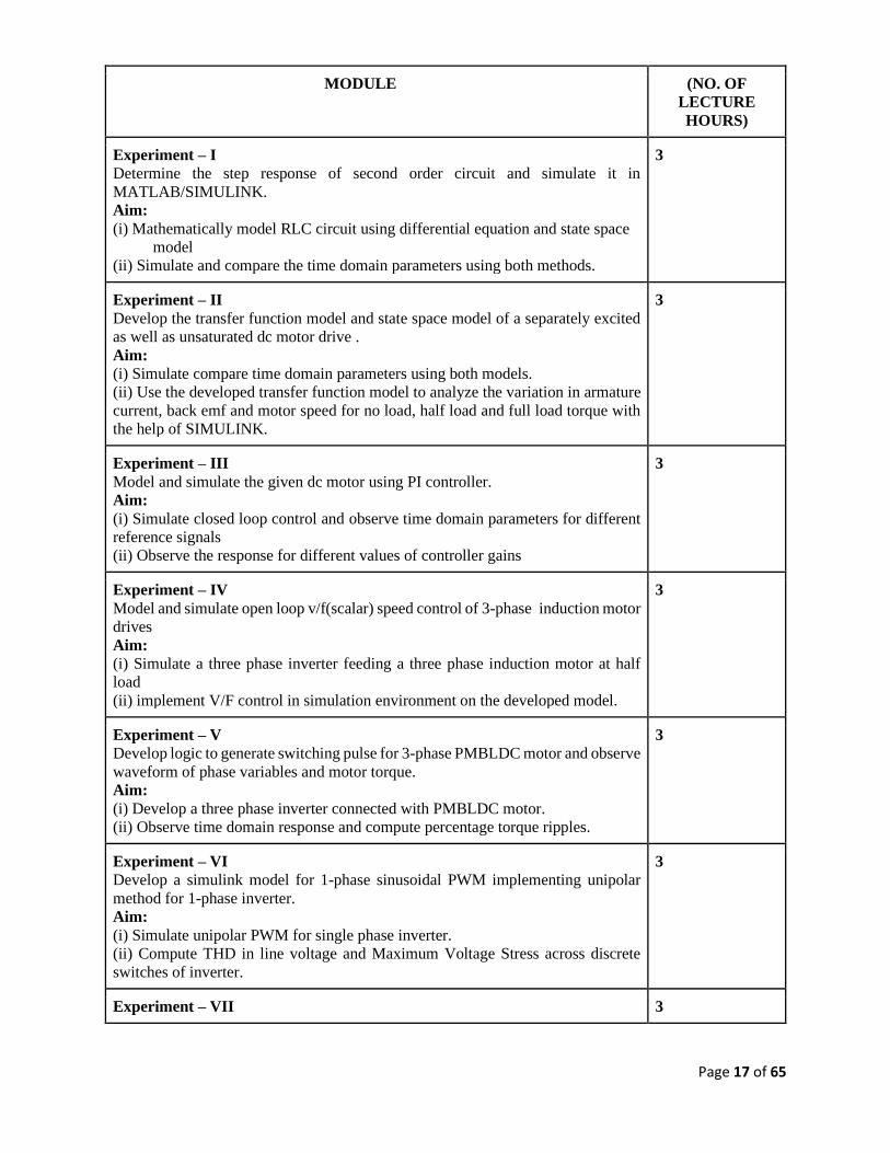
Experiment – I
Determine the step response of second order circuit and simulate it in
MATLAB/SIMULINK.
Aim:
(i) Mathematically model RLC circuit using differential equation and state space
model
(ii) Simulate and compare the time domain parameters using both methods.
3
Experiment – II
Develop the transfer function model and state space model of a separately excited
as well as unsaturated dc motor drive .
Aim:
(i) Simulate compare time domain parameters using both models.
(ii) Use the developed transfer function model to analyze the variation in armature
current, back emf and motor speed for no load, half load and full load torque with
the help of SIMULINK.
3
Experiment – III
Model and simulate the given dc motor using PI controller.
Aim:
(i) Simulate closed loop control and observe time domain parameters for different
reference signals
(ii) Observe the response for different values of controller gains
3
Experiment – IV
Model and simulate open loop v/f(scalar) speed control of 3-phase induction motor
drives
Aim:
(i) Simulate a three phase inverter feeding a three phase induction motor at half
load
(ii) implement V/F control in simulation environment on the developed model.
3
Experiment – V
Develop logic to generate switching pulse for 3-phase PMBLDC motor and observe
waveform of phase variables and motor torque.
Aim:
(i) Develop a three phase inverter connected with PMBLDC motor.
(ii) Observe time domain response and compute percentage torque ripples.
3
Experiment – VI
Develop a simulink model for 1-phase sinusoidal PWM implementing unipolar
method for 1-phase inverter.
Aim:
(i) Simulate unipolar PWM for single phase inverter.
(ii) Compute THD in line voltage and Maximum Voltage Stress across discrete
switches of inverter.
3
Experiment – VII 3

Page 18 of 65
Develop a simulink model for 3-phase sinusoidal PWM implementing bipolar
method for 3-phase voltage source inverter.
Aim:
(i) Simulate bipolar PWM for three phase inverter.
(ii) Compute THD in line voltage and Phase voltage and Maximum Voltage Stress
across discrete switches of inverter.
Experiment – VIII
Design a simulink model for implementing a DC-DC boost converter.
Aim:
(i) Develop state space model for DC-DC boost converter.
(ii) Compare time domain response of the models developed using state space
model of DC-DC boost converter and Power Library of boost converter.
3
Experiment – IX
Implement a PV solar panel module in MATLAB(SIMULINK) and study its PV
and VI curve.
Aim:
(i) Develop a mathematical model for PV cell.
(ii) Obtain its PV and VI characteristics using variable load.
3
Experiment – X
Design and implementation of MPPT algorithm for a standalone PV system.
Aim:
(i) Develop MPPT algorithm in script function file of MATLAB
(ii) Implement MPPT algorithm for a fixed load.
3
Text Books:
1. Rudra Pratap: Getting Started with MATLAB: A Quick Introduction for Scientists and Engineers,
2002, Oxford University Press
2. M.H. Rashid, Power Electronics, PHI,
Reference Books:
1. B K Bose: Modern Power Electronics and A C Drives, 2001, Delhi, PHI.
2. G K Dubey, Fundamental of Electric Drives, 2nd Edition, PHI, Delhi.
3. C.M. Ong, Dynamic Simulation of Electric Machinery, PH, NJ.
Gaps in the syllabus :
Real Time Simulation
POs met through Gaps in the Syllabus:
PO (4,5)
Topics beyond syllabus/Advanced topics/Design :
Real time simulation of V/F control using DSPACE real time simulator
POs met through Topics beyond syllabus/Advanced topics/Design:
PO (4,5)
Course Outcome (CO) Attainment Assessment Tools & Evaluation Procedure
Direct Assessment
Assessment Tool % Contribution during CO
Assessment

Page 19 of 65
Progressive
Evaluation
Day to day performance & Lab
files
30
Quiz 10
Viva 20
End Semester Examination Experiment
Performance
30
Quiz 10
Indirect Assessment
1. Students’ Feedback on Course Outcome.
Mapping of Course Outcomes onto Program Outcomes
Course
Outcome
Program Outcomes (POs) Program Specific Outcomes
(PSOs)
1 2 3 4 5 6 7 8 9 10 11 12 13 14 15
CO1 3 3 3 3 3 3 2 2 2 2 2 1 3 2 2
CO2 3 3 3 3 3 3 3 3 2 2 2 2 3 2 2
CO3 3 3 3 3 3 3 3 3 3 2 2 2 3 3 2
CO4 3 3 3 3 3 3 3 3 3 3 2 2 3 3 3
CO5 3 3 3 3 3 3 3 3 3 3 3 2 3 3 3
Correlation Levels 1, 2 or 3 as defined below:
1: Slight (Low) 2: Moderate (Medium) 3: Substantial (High)
Mapping Between COs and Course Delivery (CD) methods
CD
Code
Course Delivery Methods Course
Outcome
Course Delivery
Method Used
CD1 Lecture by use of Boards/LCD Projectors CO1 CD1, CD7, CD 8

Page 20 of 65
CD2 Tutorials/Assignments CO2 CD1 and CD9
CD3 Seminars CO3 CD1, CD2 and CD3
CD4 Mini Projects/Projects CO4 CD1 and CD2
CD5 Laboratory Experiments/Teaching Aids CO5 CD1 and CD2
CD6 Industrial/Guest Lectures
CD7 Industrial Visits/In-plant Training
CD8 Self- learning such as use of NPTEL
Materials and Internets
CD9 Simulation

Page 21 of 65
Programme Elective-III

Page 22 of 65
COURSE INFORMATION SHEET
Course code: EE573
Course title: Embedded Systems and Applications
Pre-requisite(s): Microprocessor and Microcontroller
Co- requisite(s): Digital Electronics and C programming
Credits: L: T: P:
3 0 0
Class schedule per week: 03
Class: B.Tech.
Semester / Level: VII / IV
Branch:EEE
Name of Teacher:
Course Objectives:
This course envisions to impart to students to:
1. Comprehend the basic functions, structure, concept and definition of embedded systems.
2. Interpret ATMEGA8 microcontroller and TMS320C6713 processors in the development of
embedded systems.
3. Correlate different serial interfacing protocols (SPI, TWI, I2C, USART).
4. Understand interfacing of different peripherals (ADC, DAC, LCD, motors).
5. Evaluate design cost of any given embedded system application.
Course Outcomes:
After the completion of this course, students will be able to:
CO1 Visualize the basic elements and functions of ATMEGA8 in building an embedded system.
CO2 Work with modern hardware/software tools for building prototypes of embedded systems.
CO3 Interface various sensors, ADC, DAC, LCD, stepper motors with ATMEGA8.
CO4 Employ various bus protocols like SPI, TWI, I2C for interfacing peripherals.
CO5 Apply design methodologies for embedded systems, while appreciating the considerations for
embedded systems design: specification, technological choice, development process, technical,

Page 23 of 65
economic, environmental and manufacturing constraints, reliability, security and safety, power
and performance.
SYLLABUS :
MODULE (NO. OF
LECTURE
HOURS)
MODULE – I
Introduction & Basic Concepts of Computer Architecture: Embedded Systems
Overview, Processor technology- General purpose processors (Software), Single purpose
processors (Hardware), Application- Specific processors; IC Technology- Full-
custom/VLSI, Semicustom ASIC (Gate Array and standard cell), PLD Computer
Architecture Concepts Memory, Input/ Output, DMA, Parallel and Distributed
computers, Embedded Computer Architecture, Brief Introduction to FPGA processor.
6
MODULE – II
Embedded Processors & Systems: Atmel AVR ATMEGA 8 Micro-controller
Introduction, Major features, Architecture, Application and programming,
Timers/Counters, ADC, USART, SPI, TWI, Vectored Interrupts with emphasis on
external interrupts.
10
MODULE – III
DSP-based controllers: Texas Instrument’s TMS320C6713 DSP processor
Introduction, Major features, Architecture, Application and programming, Brief
Introduction to TMS320C28335.
6
MODULE – IV
Peripherals and Interfacing: Adding Peripherals and Interfacing- Serial Peripherals and
Interfacing- Serial Peripheral Interface (SPI) Inter Integrated Circuit (I2C), Adding a
Real- Time Clock with I2C, Adding a Small Display with I2C Serial Ports - UARTs, RS-
232C & RS-422, Infrared Communication, . USB, Networks- RS-485, Controller Area
Network (CAN), Ethernet Analog Sensors - Interfacing External ADC, Temperature
Sensor, Light Sensor, Accelerometer, Pressure Sensors, Magnetic - Field Sensor, DAC.
12
MODULE – V
Embedded System for Motor Control: PWM; Embedded System Applications - Motor
Control, Motor Control, and Switching Big Loads
8
Text books:
1. Catsoulis, John, "Designing Embedded Hardware", First/Second Edition, Shroff Publishers &
Distributors Pvt. Ltd., New Delhi, India.

Page 24 of 65
2. Vahid, Frank and Givargis, Tony, "Embedded System Design - A Unified hardware/Software
Introduction", John Wiley & Sons, (Asia) Pvt Ltd., Replika Press Pvt., Delhi - 110040.
3. Mazidi & Mazidi, "AVR Microcontrollers & Embedded Systems using Assembly & C Pearson
Education
4. Rulph Chassaing, “Digital Signal Processing and Applications with C6713 and C6416 DSK”,
John Wiley and Sons publication
Reference books:
1. Stuart R. Ball, “Embedded Microprocessor Systems, Real World Design”, Second Edition,
Newnes publication.
2. Nasser Kehtarnavaz, “Real Time Digital Signal Processing based on the TMS320C6000”,
Elsevier publication.
Gaps in the syllabus :
Computation of algorithm complexity
POs met through Gaps in the Syllabus:
PO (4)
Topics beyond syllabus/Advanced topics/Design :
Assignment: Compute number of clock cycles required for UART and RS232 Communication
POs met through Topics beyond syllabus/Advanced topics/Design:
PO (4)
Course Outcome (CO) Attainment Assessment Tools & Evaluation Procedure
Direct Assessment
Assessment Tool % Contribution during CO Assessment
First Quiz 10
Mid Semester Examination 25
Second Quiz 10
Teacher’s Assessment 5
End Semester Examination 50
Indirect Assessment
1. Students’ Feedback on Course Outcome.
Mapping of Course Outcomes onto Program Outcomes

Page 25 of 65
Course
Outcome
Program Outcomes (POs) Program
Specific
Outcomes
(PSOs)
1 2 3 4 5 6 7 8 9 10 11 12 13 14 15
CO1 3 3 3 2 2 2 2 1 1 1 1 2 3 2 1
CO2 3 3 3 3 3 2 2 2 1 1 1 2 3 2 2
CO3 3 3 3 3 3 3 3 2 2 2 2 2 3 3 2
CO4 3 3 3 3 3 3 3 3 3 3 2 2 3 3 3
CO5 3 3 3 3 3 3 3 3 3 3 3 3 3 3 3
Correlation Levels 1, 2 or 3 as defined below:
1: Slight (Low) 2: Moderate (Medium) 3: Substantial (High)
Mapping Between COs and Course Delivery (CD) methods
CD
Code
Course Delivery Methods Course
Outcome
Course Delivery
Method Used
CD1 Lecture by use of Boards/LCD Projectors CO1 CD1, CD7, CD 8
CD2 Tutorials/Assignments CO2 CD1 and CD9
CD3 Seminars CO3 CD1, CD2 and CD3
CD4 Mini Projects/Projects CO4 CD1 and CD2
CD5 Laboratory Experiments/Teaching Aids CO5 CD1 and CD2
CD6 Industrial/Guest Lectures
CD7 Industrial Visits/In-plant Training

Page 26 of 65
CD8 Self- learning such as use of NPTEL
Materials and Internets
CD9 Simulation
Course Information Sheet
Course Code: EE 531
Course Title: EHV AC Power Transmission
Pre-requisite(s): Knowledge of Physics, Mathematics, Principle of Electrical Engineering,
Electromagnetic Theory, Power System Transmission and Distribution
Switch Gear and Protection
Co- requisite(s): Credits: L: T: P:
3 0 0
Class schedule per week: 03
Class: B. Tech.
Semester / Level: VII/IV
Branch: EEE
Name of Teacher:
Course Objectives
This course envisions imparting the following objectives to students:
A. To provide the concept of calculation line resistance, inductance, capacitance and
ground return parameters for N-conductor bundle
B. To make the students understand the field of point charge, line charge and then surface
voltage gradient for bundle conductor.
C. To expose the effect of compensators in voltage dynamic of EHV buses.
D. To expose the students about the calculation process of electrostatic and
electromagnetic field for bundle conductor and their effects.
E. To provide the core concept of HVDC system and the working principles of
converters, harmonic generation and filtration.
Course Outcomes
After the completion of this course, students will be able to:
1. To determine the line parameters of bundle conductors.

Page 27 of 65
2. To formulate the mathematical equations for different factors that causes the operational
limitations for EHVline like surface voltage gradients, electrostatic field.
3. To determine the required size of compensators for EHV line.
4. To understand the core concept involving the different components in schematic diagram
of HVDC system and their performance.
5. To understand the nature of harmonics generated by converters and to comprehend the
importance of filter.

Page 28 of 65
SYLLABUS :
MODULE
(NO. OF
LECTURE
HOURS)
Module – I
Maxwell’s coefficients, Sequence inductance and capacitance, Charge Matrix,
Effect of Ground wire.
10
Module – II
Surface Voltage-gradient on bundled conductors, Mangoldt’s formula, Gradient
factors & their use, Ground level electrostatic field of EHV lines.
10
Module – III
Power frequency over-voltage control, Series and shunt compensation,
Generalised Constants of Compensated line, Static Var Compensators
(SVC/SVS). Switching over-voltages in EHV Systems
7
Module – IV
Six-pulse Bridge Circuit: waveforms and relevant equations, Twelve-pulse
converter, Advantages of higher pulse number, Bipolar to monopolar operation,
Converter performance with phase control, Commutation and effect of reactance
8
Module – V
Introduction to HVDC Transmission system, Economical advantages, Technical
advantages, Critical distance, Submarine transmission. Inverter, Equivalent
circuit of HVDC system, Schematic diagram, Reactive power consideration in
HVDC system, Harmonics, Filters in HVDC system.
5
Text Books:
1. Extra High Voltage AC Transmission Engineering (2nd Ed.) by R.D. Begamudre, Wiley
Eastern Ltd. 2. HVDC Power Transmission Systems by K. Padiyar, Wiley Eastern Ltd.
Course Outcome (CO) Attainment Assessment Tools & Evaluation Procedure
Direct Assessment
Assessment Tool % Contribution during CO Assessment
First Quiz 10
Mid Semester Examination 25
Second Quiz 10
Teacher’s Assessment 5
End Semester Examination 50
Indirect Assessment
1. Students’ Feedback on Course Outcome.

Page 29 of 65
Mapping of Course Outcomes onto Program Outcomes
Course
Outcome
Program Outcomes (POs)
Program
Specific
Outcomes
(PSOs)
1 2 3 4 5 6 7 8 9 10 11 12 13 14 15
CO1 3 3 3 1 3 1 1 1 2 3 2 2
CO2 3 3 3 1 3 1 1 1 2 3 2 2
CO3 3 3 3 3 3 1 2 2 1 1 2 3 2 2
CO4 3 3 3 1 3 1 1 1 1 2 3 2 2
CO5 3 3 3 3 3 1 1 1 1 1 1 2 3 2 2
Correlation Levels 1, 2 or 3 as defined below:
1: Slight (Low) 2: Moderate (Medium) 3: Substantial (High)
Mapping Between COs and Course Delivery (CD) methods
CD
Code Course Delivery Methods
Course
Outcome
Course Delivery
Method Used
CD1 Lecture by use of Boards/LCD Projectors CO1 CD1, CD7, CD 8
CD2 Tutorials/Assignments CO2 CD1 and CD9
CD3 Seminars CO3 CD1, CD2 and CD3
CD4 Mini Projects/Projects CO4 CD1 and CD2
CD5 Laboratory Experiments/Teaching Aids CO5 CD1 and CD2
CD6 Industrial/Guest Lectures
CD7 Industrial Visits/In-plant Training
CD8 Self- learning such as use of NPTEL Materials and
Internets
CD9 Simulation

Page 30 of 65
COURSE INFORMATION SHEET
Course code: EE 437
Course title: INDUSTRIAL DRIVES AND CONTROL
Pre-requisite(s): Principles of Electrical Engineering, Electrical Machines, Power Electronics
Co- requisite(s):
Credits: L: T: P:
3 0 0
Class schedule per week: 03
Class: B. Tech.
Semester / Level: VII/IV
Branch: EEE
Name of Teacher:
Course Objectives
This course envisions to impart to students to:
A. explain the components of an electric drive system and understand their functions;
B. describe the dynamics of an electromechanical system;
C. choose an appropriate electric drive as per the application and requirements;
D. select a proper size of the motor as per the load requirements and develop the closed
loop control and asses the performance of the drive in terms of stability, capabilities
of regeneration and flexibility in control.
Course Outcomes
After the completion of this course, students will be able to:
1. define an electric drive system and its component and determine the load parameters
such as equivalent moment of inertia and load torque;
2. develop dynamic model of an electric drive and carry out stability analysis and explain
the necessity and different types of load equalization;
3. use the information of different class of duty and thermal model to choose appropriate
size of a motor for a given application;
4. define the speed torque characteristics, different zone of operation, starting and braking
of a dc-motor and ac-motor (viz. induction motor, squirrel cage induction motor, and
synchronous motor) and develop the close loop control of a dc-motor/ac-motor drive and
understand the mechanism of train movement and develop a controller for traction motor
so that he/she can apply theoretical knowledge into practical system;
5. aspire a career with specialization in field of electric drive more and recognize the need
to learn engage and adopt in the world of constantly changing electric drive technology.

Page 31 of 65
SYLLABUS :
MODULE
(NO. OF
LECTURE
HOURS)
Module – I
Electrical Drives: An Introduction, Parts of Electrical Drives; ac and dc Drives,
fundamental torque equations, Speed torque conventions and multi-quadrant
operation; calculation of equivalent drive parameters, Different load torques and
their nature; steady state stability; load equalization.
6
Module – II
Selection of Motor rating and its control: Introduction, thermal model of a motor,
Classes of Motor Duty cycle, selection of motor and its rating, Closed-loop and
open loop control of drives, Modes of Operation; speed control & Drive
classifications; closed - loop control of Drives; speed and current sensing; manual,
semi-automatic & automatic control.
6
Module – III
D.C. Motor Drives: Introduction, Performance characteristics of DC Motors &
their Modifications; Starting of DC motors & their Design, Electric Braking;
Speed Control of DC motor; Converter controlled DC Drives; Single phase
converter drives, three phase converter drives, Dual converter drives, Chopper
controlled dc drives, Closed loop control of dc motor, selection of components
and their specifications for Dc drives.
6
Module – IV
Phase Controlled Induction Motor Drives: Introduction, Speed-torque
characteristics, Starting & Braking of IM; effects of unbalancing and harmonics
on IM, Speed Control techniques, Stator voltage control, Closed Loop schemes
for phase controlled IM drives, Rotor resistance control, Slip speed control, Slip
power recovery schemes. Frequency Controlled Induction Motor Drives: Scalar
control, Variable frequency control, constant volts/Hz control, Voltage source
inverter (VSI) control using PWM techniques, Closed Loop speed control of VSI
drives, Control from a current source Inverter(CSI), Closed Loop speed control
of CSI drives, Comparison of CSI and VSI drives. Selection of components and
their specification for AC drives.
12
Module – V
Synchronous Motor Drives: Starting, Pull-in and Braking with Fixed Frequency
Supply; Variable Speed Drives, Cyclo-converter based Synchronous motor
control, control of Trapezoidal PMAC motor, Close loop speed control of
Synchronous Machines.
5
Text Books:

Page 32 of 65
1. G.K. Dubey, Fundamentals of Electrical Drives, Narosa publication, New Delhi
2. R. Krishnan, Electric Motor Drives-modeling, analysis and control.
Reference Books: 1. S.K.Bhattacharya&Brijinder Singh, Control of Electrical Machines
2. Mukhtar Ahmad, Industrial Drives and Control
3. S.K.Pillai, A first course on Electrical Drives
4. M. Chilikin, Electric Drives.
5. C. L. Wadhwa, Genaration Distribution and Utilization of Electrical energy
Gaps in the Syllabus (to meet Industry/Profession requirements) Simultaneous lab experiments should be in the same semester.
POs met through Gaps in the Syllabus
3 and 4.
Topics beyond syllabus/Advanced topics/Design
POs met through Topics beyond syllabus/Advanced topics/Design
Course Outcome (CO) Attainment Assessment Tools & Evaluation Procedure
Direct Assessment
Assessment Tool % Contribution during CO Assessment
First Quiz 10
Mid Semester Examination 25
Second Quiz 10
Teacher’s Assessment 5
End Semester Examination 50
Indirect Assessment
1. Students’ Feedback on Course Outcome.
Mapping of Course Outcomes onto Program Outcomes

Page 33 of 65
Course
Outcome
Program Outcomes (POs)
Program
Specific
Outcomes
(PSOs)
1 2 3 4 5 6 7 8 9 10 11 12 13 14 15
CO1 3 2 3 2 2 1 1 3 2 2 3 3 3 3 2
CO2 3 3 2 2 1 2 1 3 2 3 2 3 2 3 3
CO3 3 3 3 1 2 1 1 2 2 3 1 3 3 2 1
CO4 2 2 3 1 2 1 3 2 2 1 2 2 3 3 3
CO5 2 3 2 1 2 1 3 3 1 2 1 3 3 3 2
Correlation Levels 1, 2 or 3 as defined below:
1: Slight (Low) 2: Moderate (Medium) 3: Substantial (High)
Mapping Between COs and Course Delivery (CD) methods
CD
Code Course Delivery Methods
Course
Outcome
Course Delivery
Method Used
CD1 Lecture by use of Boards/LCD Projectors
CO1 CD1,CD2,CD8
CD2 Tutorials/Assignments
CO2 CD1,CD2
CD3 Seminars
CO3 CD1,CD2,CD8
CD4 Mini Projects/Projects
CO4 CD1,CD2,CD8
CD5 Laboratory Experiments/Teaching Aids
CO5 CD1,CD2,CD8
CD6 Industrial/Guest Lectures
CD7 Industrial Visits/In-plant Training
CD8 Self- learning such as use of NPTEL Materials and
Internets
CD9 Simulation

Page 34 of 65
COURSE INFORMATION SHEET
Course code: EE 439
Course title: Applied Control Theory
Pre-requisite(s): Basic electrical, physic system theory and fundamental of control
system
Co- requisite(s): Credits: L: T: P:
3 0 0
Class schedule per week: 03
Class: B. Tech.
Semester / Level: VII/IV
Branch: EEE
Name of Teacher:
Course Objectives
This course envisions to impart to students to:
A. To acquaint students with concepts of state variables.
B. To deliver comprehensive knowledge of mathematical modelling of linear/nonlinear
system.
C. To elucidate basics of designing the control problem.
D. To brief them on theory of adaptive control theory.
E. To acquaint students with concepts of nonlinearity in control problem.
Course Outcomes
After the completion of this course, students will be able to:
1. Find out the ABCD parameter of a system
2. Able to solve the pole placement design
3. Simulate the control problem and analyses
4. Handle the nonlinearity in control system design
5. Able to design and provide a control topology for given engineering system.
SYLLABUS :

Page 35 of 65
MODULE
(NO. OF
LECTURE
HOURS)
Module – I
Concepts of State, State Variables:
Development of state-space models. State and state equations, State
equations from transfer function Transfer function from state equations.
State transition matrix, Solution of State equation, Transfer Matrix, State
variables and linear discrete time systems.
8
Module – II
Controllability and Observability:
Controllable and observable State models, Controllability and observability
for discrete time systems.
8
Module – III
State Variable Feedback:
Asymptotic state observers. Control system design via pole placement.
8
Module – IV
Optimal Control Systems:
Introduction, Performance indices, Optimal control problems- Transfer
function approach, State variable approach; Parameter optimization.Stability
of Non-Linear Systems: Stability concepts. Stability analysis using
Lyapunov’sDirect method; Popov’s stability criterion.
8
Module – V
Non-Linear Systems:
Introduction. Common nonlinearities. Methods of studying non-linear
systems: Linearization; Describing function analysis; Phase plane analysis.
Adaptive Control Systems: Performance indices. Adaptive Controllers,
Identification of dynamic characteristics of the plant
8
Text books:
1. Control Systems Engineering- I.J. Nagrath& M. Gopal.
Reference books:
1. Modern Control System Theory- M. Gopal.
2. Modern Control Engineering- K. Ogata.
3. Control Systems- N. K. Sinha.

Page 36 of 65
Gaps in the Syllabus (to meet Industry/Profession requirements)
1. Transducer and sensor mathematical model.
2. Real time simulation and analysis of control system.
3. Application of artificial intelligent topology for control system.
POs met through Gaps in the Syllabus
3, 4, 12
Topics beyond syllabus/Advanced topics/Design
1. Digital signal processing.
2. Actuator and sensor molding.
3. Neural network and AI system.
POs met through Topics beyond syllabus/Advanced topics/Design
3, 4, 12
Course Outcome (CO) Attainment Assessment Tools & Evaluation Procedure
Direct Assessment
Assessment Tool % Contribution during CO Assessment
First Quiz 10
Mid Semester Examination 25
Second Quiz 10
Teacher’s Assessment 5
End Semester Examination 50
Indirect Assessment
1. Students’ Feedback on Course Outcome.
Mapping of Course Outcomes onto Program Outcomes
Course
Outcome
Program Outcomes (POs)
Program
Specific
Outcomes
(PSOs)
1 2 3 4 5 6 7 8 9 10 11 12 13 14 15
CO1 3 3 3 1 3 1 1 1 2 3 2 3

Page 37 of 65
CO2 3 3 3 1 3 1 1 1 2 3 2 3
CO3 3 3 3 3 3 1 2 2 1 1 2 3 2 3
CO4 3 3 3 1 3 1 1 1 1 2 3 2 3
CO5 3 3 3 3 3 1 1 1 1 1 1 2 3 3 3
Correlation Levels 1, 2 or 3 as defined below:
1: Slight (Low) 2: Moderate (Medium) 3: Substantial (High)
Mapping Between COs and Course Delivery (CD) methods
CD
Code Course Delivery Methods
Course
Outcome
Course Delivery
Method Used
CD1 Lecture by use of Boards/LCD Projectors CO1 CD1, CD7, CD 8
CD2 Tutorials/Assignments CO2 CD1 and CD9
CD3 Seminars CO3 CD1, CD2 and CD3
CD4 Mini Projects/Projects CO4 CD1 and CD2
CD5 Laboratory Experiments/Teaching Aids CO5 CD1 and CD2
CD6 Industrial/Guest Lectures
CD7 Industrial Visits/In-plant Training
CD8 Self- learning such as use of NPTEL Materials and
Internets
CD9 Simulation

Page 38 of 65
Course Information Sheet
Course Code: EE 441
Course Title: Computer Aided Power System Analysis
Pre-requisite(s): Knowledge of basic principles of power system and its analysis
Co- requisite(s): Credits: L: T: P:
3 0 0
Class schedule per week: 03
Class: B. Tech.
Semester / Level: VII/IV
Branch: Electrical & Electronics Engineering
Name of Teacher:
Course Objectives :
This course envisions imparting the following objectives to students:
A. To understand single-phase modeling of power system components and their input
parameters for computer programming.
B. To expose the students about efficient numerical methods suitable for computer
simulation for the solution of the power flow problems.
C. To make the students understand about fault current ad bus bar voltages under
abnormal (fault) conditions utilizing bus impedance matrix.
D. To understand the economic load dispatch and unit commitment problem and their
solution techniques.
E. To assess optimal system operation and infer about the dynamics of power systems
for small and large disturbances.
Course Outcomes :
After completion of the course, the learners will be able :
1. To identify and list input parameters to start with software-based solution.
2. To solve the load flow problems by different techniques and their advantages.
3. To identify and analyze the different abnormal (fault) conditions in power system
utilizing efficient computer algorithm.

Page 39 of 65
4. To solve economic load dispatch problem with and without transmission losses
and also to solve unit commitment problem by Dynamic programming method.
5. To formulate different methods of improving the transient stability of a large
practical power system.
Syllabus:
MODULE
(NO. OF
LECTURE
HOURS)
Module – I
Introduction: The new computer environment, Basic single-phase modeling-
Generator, Transmission lines, Transformer- Off nominal transfer tap
representation, Phase shifting representation.
10
Module – II
Load Flow Analysis: Introduction, Nature of load flow equations,
Computational steps and flow chart of Gauss Seidel Techniques, Newton
Raphson method: Formulation for load buses and voltage-controlled buses in
rectangular and polar co-ordinates, Computational steps and flow chart.
Computational Aspects of Large-Scale System: Sparsity of Ybus and Jacobian
matrix, Sparsity oriented computer programming, Reducing storage requirement,
Decoupled power flow algorithm
10
Module – III
Optimal System Operation: Introduction, Characteristic of steam and hydro
units, Economic dispatch of thermal units, Equal incremental cost operation,
Computational steps, Transmission loss and incremental transmission loss (ITL),
Computational aspects.
Unit Commitment: Introduction, Objective function, Constraints, Dynamic
programming method.
7
Module – IV
Short Circuit Analysis: Introduction, Bus impedance matrix and its building
algorithm through modifications, Symmetrical and unsymmetrical fault
calculation using Zbus and its computational steps.
8
Module – V
Power System Stability: Stability problem, swing equation and its numerical
solution, Determination of initial state in a multi-machine system, Base case Y-
BUS and modified Y-BUS, Computational algorithm, Improvement of stability.
5
TEXT BOOKS:
1. Power system Analysis—Grainger and Stevension—Tata-McGraw Hill, New Delhi.
2. Advanced Power System Analysis and Dynamics - L. P. Singh, New Age
International, 4th edition, 2006.

Page 40 of 65
REFERENCE BOOKS:
1. Computer Modelling of Electrical Power Systems - J. Arrillaga, N.R. Watson, Wiley, 2nd
edition, 2001.
2. Power Generation Operation and Control - A.J. Wood, B.F. Wollenberg, 2nd edition
Wiley Inderscience publication.
3. Computer Techniques in Power System Analysis – M. A. Pai, McGraw Hill, New
Delhi, 2nd edition, 2003.
Gaps in the syllabus (to meet Industry/Profession requirements)
1. Impact of Deregulation in Power Industry
2. Computer Simulation incorporating impact of Renewable Sources in Power System.
POs met through Gaps in the Syllabus: 3, 4 and 5
Topics beyond syllabus/Advanced topics/Design: Load flow considering RES, MATLAB
Simulation of power system network.
POs met through Topics beyond syllabus/Advanced topics/Design: 3,4 and 5
Course Outcome (CO) Attainment Assessment Tools & Evaluation Procedure
Direct Assessment
Assessment Tool % Contribution during CO Assessment
First Quiz 10
Mid Semester Examination 25
Second Quiz 10
Teacher’s Assessment 5
End Semester Examination 50
Indirect Assessment
1. Students’ Feedback on Course Outcome.
Mapping of Course Outcomes onto Program Outcomes
Course
Outcome Program Outcomes (POs)
Program
Specific

Page 41 of 65
Outcomes
(PSOs)
1 2 3 4 5 6 7 8 9 10 11 12 13 14 15
CO1 3 3 - - - 1 - 2 1 1 - - 2 2 1
CO2 3 3 2 2 3 2 1 1 1 1 - 1 3 2 2
CO3 3 2 2 2 2 2 3 1 1 1 - 1 3 2 2
CO4 3 3 3 2 2 2 2 1 1 1 3 1 3 2 2
CO5 3 3 2 2 2 2 2 1 1 1 3 1 3 2 2
Correlation Levels 1, 2 or 3 as defined below:
1: Slight (Low) 2: Moderate (Medium) 3: Substantial (High)
Mapping Between COs and Course Delivery (CD) methods
CD
Code Course Delivery Methods
Course
Outcome
Course Delivery
Method Used
CD1 Lecture by use of Boards/LCD Projectors CO1 CD1, CD7, CD 8
CD2 Tutorials/Assignments CO2 CD1 and CD9
CD3 Seminars CO3 CD1, CD2 and CD3
CD4 Mini Projects/Projects CO4 CD1 and CD2
CD5 Laboratory Experiments/Teaching Aids CO5 CD1 and CD2
CD6 Industrial/Guest Lectures
CD7 Industrial Visits/In-plant Training
CD8 Self- learning such as use of NPTEL Materials and
Internets
CD9 Simulation

Page 42 of 65
Programme Elective-IV

Page 43 of 65
COURSE INFORMATION SHEET
Course code: EE 593
Course title: High Voltage Engineering
Pre-requisite(s): Fundamental of Electrical and Electronics Engineering, Electromagnetics Field,
Electrical Measurement, Electrical Insulating Material
Co- requisite(s): Credits: L: T: P:
3 0 0
Class schedule per week: 3
Class: B.Tech.
Semester / Level: VII/ IV
Branch: EEE
Name of Teacher:
Course Objectives:
This course enables the students to :
A. To educate students about electric field stress
B. To give an exposure about different types of electrical insulation
C. To give information about conduction and breakdown in different types of electrical insulation
D. To impart knowledge about the methods of generation and measurement of high voltage and
current for testing
E. To train the students for design of high voltage laboratory
Course Outcomes:
Student will be able to:
A. gain skilful knowledge of controlling the electrical stress in electrical systems and proper use
of electrical insulating media.
B. perform experiments on generation and measurement of high voltage and current
C. identify possible reasons for failure of electrical insulation
D. explore remedial measure for failure of electrical insulation.
E. design circuits for generation of high voltage and current, electrical insulation system and set
up high voltage lab
Syllabus:
MODULE
(NO. OF
LECTURE
HOURS)
Module – I
3

Page 44 of 65
Introduction: Electric Field Stresses, Gas/Vacuum as Insulator, Liquid Breakdown,
Solid Breakdown, Estimation and Control of Electric Stress
Module – II
Conduction and Breakdown in Gases: Gases as Insulating Media, Ionization
Processes, Townsend's Current Growth Equation, Townsend's Criterion for Breakdown,
Breakdown in Electronegative Gases, Time Lags for Breakdown, Streamer Theory of
Breakdown in Gases, Paschen's Law, Breakdown in Non-Uniform Fields and Corona
Discharges, Post-Breakdown Phenomena and Applications, Vacuum Insulation.
6
Module – III
Conduction and Breakdown in Liquid: Liquids as Insulators, Pure Liquids and
Commercial Liquids, Conduction and Breakdown in Pure and Commercial Liquids
Conduction and Breakdown Solid Dielectrics: Introduction, Intrinsic Breakdown,
Electromechanical and Thermal Breakdown, Breakdown of Solid Dielectrics in
Practice, Breakdown in Composite Dielectrics.
12
Module – IV
Generation High Voltage and Currents: Generation of High dc voltages, Generation
of High alternating voltages, Generation of impulse voltages, Generation of impulse
currents, Tripping and control of impulse generators.
Measurement of High Voltage and Currents: Measurement of High direct current
voltages, Measurement of High ac and impulse voltages, Measurement of High impulse
currents
8+8
Module – V
Design, Planning and Layout of High Voltage Laboratories: Introduction, Test
Facilities provided in high voltage laboratories, Activities and studies in high voltage
laboratories, Classification of high voltage laboratories, Size and Rating of large size
high voltage laboratories, Grounding of impulse testing laboratories
3
Text Book:
1. High Voltage Engineering, MS Naidu and V. Kamaraju, 4th edition, TMH New Delhi.
2. High Voltage Engineering Fundamentals, E. Kuffel and W S Zaengl, Pergamon Press, Oxford.
Reference Book:
1. High Voltage Engineering, C L Wadhwa, 2nd edition, New Age International (P) Limited,
Publishers, New Delhi.
2. Electrical Breakdown of Gases, 2nd edition, JM, Meek and JD, Crages, John Wiley, New York.
Gaps in the syllabus (to meet Industry/Profession requirements):
HVDC and HVAC Power Transmission, Insulation Coordination
POs met through Gaps in the Syllabus: d, e, h

Page 45 of 65
Topics beyond syllabus/Advanced topics/Design:
Insulation simulation and design using software, Lightning
POs met through Topics beyond syllabus/Advanced topics/Design: f
Course Outcome (CO) Attainment Assessment tools & Evaluation procedure
Direct Assessment
Assessment Tool % Contribution during CO Assessment
Mid Sem Examination Marks 25
End Seml Examination Marks 60
Assignment 15
Asseessment Compoents CO1 CO2 CO3 CO4 CO5
Mid Sem Examination Marks √ √ √ End Sem Examination Marks √ √ √ √ √ Assignment √ √ √ √ √
Indirect Assessment –
1. Student Feedback
Mapping between Course Objectives and Course Outcomes:
Course
Objectives
Course Outcomes
i ii iii iv v
1 √
2 √ √ √ √
3 √ √ √
4 √ √
5 √ √ √
Mapping between CO and PO
Course Programme Outcomes

Page 46 of 65
Outcomes a b c d e f g h i j k l
1 H M
2 H
3 H M M
4 H M L H
5 H M M M M L M M
H-High (3), M-Medium (2) and L-Low (1)
CD Course Delivery methods
CD1
Lecture by use of boards/LCD projectors/OHP
projectors
CD2 Tutorials/Assignments
CD3 Seminars
CD4 Industrial visits/in-plant training
CD5
Self- learning such as use of NPTEL materials and
internets
CD6 Simulation
Mapping Between COs and Course Delivery (CD) methods
Course
Outcome Course Delivery Method
CO1 CD1, CD2, CD3, CD4, CD5
CO2 CD1,CD2, CD4, CD5
CO3 CD1, CD2,CD5
CO4 CD1,CD5,CD6
CO5 CD1, CD5, CD6
COURSE INFORMATION SHEET

Page 47 of 65
Course code: EE 535
Course title: HVDC and FACTS Pre-requisite(s): Knowledge of basic power system and control system courses.
Co- requisite(s):
Credits: L: T: P:
3 0 0
Class schedule per week: 3
Class: B. Tech.
Semester / Level: VII/IV
Branch: EEE
Name of Teacher:
Course Objectives
This course enables the students to:
A. Identify the significance of HVDC System
B. Understanding the AC/DC conversion and its components and Interpretation of reactive power
harmonics in HVDC system.
C. Define different types of FACTS devices and their need in emerging power system.
D. Describe the operations of FACTS controller in a large-scale power system and to solve the
power flow problems using efficient numerical methods suitable for computer simulation.
Course Outcomes
After the completion of this course, students will be able to:
1. To list significance/ importance/ advantages of HVDC systems over EHVAC systems, types
and application of HVDC system
2. To explain different converters and inverters for converting AC to DC & DC to AC conversion
and to interpret the reactive power, harmonics in HVDC system, its effect and filtering.
3. Explain the operating principles, modeling and control systems of different FACTS
Controllers/Devices.
4 Solve and analyze power flow with FACTS devices using efficient numerical methods.
5. Discuss the techniques of practical FACTS controller design for various applications, such as,
enhancing power transfer, stability and damping; preventing voltage instability etc.
Syllabus:
MODULE
(NO. OF
LECTURE
HOURS)
Module – I
Introduction to HVDC transmission: Comparison with EHV AC power transmission,
HVDC system configuration and components.
Module – II
Principles of AC/DC conversion: Converter connections, Wave forms, Relevant
Equations, Reactive Power requirements
Module – III

Page 48 of 65
Harmonics and Filters : Waveforms of a-c bus currents in Star/Star, Star/delta
& 12-phase converters and their Fourier-series representations, Non-
characteristic harmonics, Harmful Effects of Harmonics, DC side harmonics,
Filters and detuning, Cost considerations of filters Module – IV
FACTS Concept and THYRISTOR-BASED FACTS CONTROLLER:
Introduction to FACTS Devices: Need for FACTS in emerging power systems –
Definitions – Types of FACTS – FACTS and High Voltage DC (HVDC)
Transmission. Static Var Compensator (SVC) – Functional description and
structures – Control components and Models – Concepts of voltage control –
Controls and Applications, MATLAB Implementation.
Module – V
VOLTAGE SOURCE CONVERTER (VSC) BASED FACTS CONTROLLER:
Static Synchronous Compensator (STATCOM): Functional description and
structure, Models, Controls and Applications, MATLAB Implementation
TEXT BOOKS:
[1] HVDC Power Transmission Systems by K. Padiyar, Wiley Eastern Ltd.
[2] Direct Current Transmission by E.W.Kimbark, Wiley InterScience-New-York
[3] R.M. Mathur and R.K. Varma, “Thyristor-Based FACTS Controllers for Electrical Transmission
Systems”, IEEE Press and John Wiley & Sons, New York, USA, Feb. 2002, ISBN: 978-0-471-20643-9
[4] Understanding of FACTS by N.G. Hingorani & L. Gyugyi, IEEE Press.
REFERENCE BOOKS:
[4] HVDC Transmission by J.Arillaga, Peter Peregrinus Ltd; London U.K.,1983
[5] Power Transmission by Direct Current by E.Uhlman, Springer Verlag, BerlinHelberg,1985
[6] N.G. Hingorani and L. Gyugyi, “Understanding FACTS”, IEEE Press, New York, USA, 1999.
[7] Y.H. Song and A.T. Johns, eds, “Flexible AC Transmission Systems (FACTS)”, IEE Press, U.K., 1999
[8] “FACTS Applications”, IEEE-PES Publication 96TP116-0, 1996.
[9] “Modeling of Power Electronics Equipment (FACTS) in Load Flow and Stability Programs”, CIGRE
TF 38.01.08, Technical Brochure 145, August 1999.
Gaps in the syllabus (to meet Industry/Profession requirements)
POs met through Gaps in the Syllabus
Topics beyond syllabus/Advanced topics/Design

Page 49 of 65
POs met through Topics beyond syllabus/Advanced topics/Design
Course Delivery methods
Lecture by use of boards/LCD projectors/OHP projectors
Tutorials/Assignments
Seminars
Mini projects/Projects
Laboratory experiments/teaching aids
Industrial/guest lectures
Industrial visits/in-plant training
Self- learning such as use of NPTEL materials and internets
Simulation
Course Outcome (CO) Attainment Assessment tools & Evaluation procedure
Direct Assessment
Assessment Tool % Contribution during CO Assessment
Mid Sem Examination Marks
End Sem Examination Marks
Assignment / Quiz (s)
Assessment Compoents CO1 CO2 CO3 CO4
Mid Sem Examination Marks
End Sem Examination Marks
Assignment
Indirect Assessment –
1. Student Feedback on Faculty
2. Student Feedback on Course Outcome
Mapping between Objectives and Outcomes Mapping of Course Outcomes onto Program Outcomes
Course Outcome # Program Outcomes
a b c d e f g h i j k l
1
2
3
4

Page 50 of 65
Mapping Between COs and Course Delivery (CD) methods
CD Course Delivery methods
Course
Outcome
Course
Delivery
Method
CD1 Lecture by use of boards/LCD projectors/OHP projectors CO1 CD1
CD2 Tutorials/Assignments CO2 CD1
CD3 Seminars CO3
CD1 and
CD2
CD4 Mini projects/Projects
CD5 Laboratory experiments/teaching aids
CD6 Industrial/guest lectures
CD7 Industrial visits/in-plant training
CD8 Self- learning such as use of NPTEL materials and internets
CD9 Simulation
COURSE INFORMATION SHEET
Course Code: EE 507
Course Title: Advanced Power Electronics
Pre-requisite(s): Power Electronics, Operating Principle of Semiconductor Devices
Co- requisite(s): Credits: L: T: P:
3 0 0
Class schedule per week: 03
Class: B. Tech.
Semester / Level: VII/IV
Branch: Electrical & Electronics Engineering
Name of Teacher:
Course Objectives
This course envisions to impart to students to:
A. Recognize of different type of modern semiconductor based switching devices and their
operating characteristics
B. Explain working principle of power converters and relate them with different area of
application
C. Capable to analyze closed loop control of electrical drives based on power converters.
D. Differentiate between different control strategy of electrical drives in terms of
dynamic parameters of system and overall efficiency.
E. Evaluate performance evaluation, plan and design procedure for a complex power
electronics based system.

Page 51 of 65
Course Outcomes
After the completion of this course, students will be able to:
1. List different types of semiconductor devices and remember their operating
characteristics. Explain working principle of different semiconductor devices
2. Classify different types of power converters. Show suitability of a power converter for a
particular application. Solve power management related problems with application of
power electronics based topologies.
3. Outline shortcomings of each class of power converters and solve them using proper
modifications. Identify potential area for power electronics applications.
4. Estimate the cost and long term impact of power electronics technology on a large scale
project of socio-economic importance.
5. Modify existing power electronics based installations. Design new power converter
topologies and Plan to develop a power processing unit for a particular requirement in
industrial plants as well as domestic applications. Lead or support a team of skilled
professionals.
SYLLABUS:
MODULE
(NO. OF
LECTURE
HOURS)
Module – I
Power Electronic Devices: (Diodes, Thyristors), Transistors, MOSFET, IGBT,
IGCT, etc. - operating principle, Static & dynamic characteristics, Data sheet
ratings; Thermal characteristics of power devices; Sample Gate drive circuits.
8
Module – II
Switched Mode Power Supply:
Forward and flyback converter circuits: operation of flyback converter and
waveforms analysis, operation of forward converter and waveforms analysis,
Double ended forward converter, Push Pull converter, Half Bridge isolated
converter, Full bridge isolated converter, Bidirectional power supplies ,small
signal analysis of DC-DC converters and closed loop control.
10
Module – III
PWM inverter modulation strategies & dual bridge: Sine wave with third
harmonic, space vector modulation and predictive current control techniques;
PWM rectifier; Input side bidirectional power flow requirement for regeneration
& Dual Thyristor Bridge.
Multi- level inverter : Basic topology and waveform, Diode clamped multilevel
inverter, Flying capacitor multilevel inverter, cascaded multilevel inverter
improvement in harmonics and high voltage application, comparison of different
multilevel inverters, application of multilevel inverters;
10
Module – IV

Page 52 of 65
Resonant Inverters: Operating principle of series resonant inverter, waveforms
analysis, switching trajectory, losses and control, Operating principle of series
resonant inverter with bidirectional switches, Frequency response of resonant
series loaded, parallel loaded, and series parallel- loaded inverter, Parallel
resonant inverter, ZCS resonant converter, ZVS resonant converter.
6
Module – V
Introduction to application oriented chips: Industrial PWM driver chips for power
supplies such as UC 3843, 3825 or equivalent; Industrial gate driver chips for
PWM voltage source inverters with isolation and protection circuits. Intelligent
power modules.
6
TEXT BOOK
1. M.H. Rashid,“Power Electronics: Circuits, Device and Applications”,2nd Ed.n, PHI, New
Jersey, 1993
2. Mohan, Underland, Robbins; Power Electronics Converters, Applications and Design, 3rd
Edn., 2003, John Wiley & Sons Pte. Ltd.
3. M. D. Singh, K. B. Khanchandani, “Power Electronics”, 2nd Edn., Tata McGraw-Hill, 2007.
REFERENCE BOOK
1. R. Krishnan, “Electric Motor Drives: Modeling, Analysis and Control”, 1st Edn., Prentice
Hall,2001
2. B. K. Bose, “Modern Power Electronics & AC Drives” , 1st Edn., Prentice Hall, 2001
3. L. Umanand, “Power Electronics: Essentials & Applications”, 1st Edn. Wiley India Private
Limited, 2009
4. Jeremy Rifkin, “Third Industrial Revolution: How Lateral Power Is Transforming Energy, the
Economy, and the World”, 1st Edn., St. Martin’s, Press, 2011
Gaps in the syllabus (to meet Industry/Profession requirements) :
(1) Cost Evaluation of Power Electronics based installation based on reliability
(2) Application of artificial intelligence in power electronics.
(3) Study of impact of power electronics on society and environment
POs met through Gaps in the Syllabus: PO6
Topics beyond syllabus/Advanced topics/Design:
(1) Reliability analysis in power electronics topologies
(2) Application of adaptive algorithms in power electronics based systems
POs met through Topics beyond syllabus/Advanced topics/Design: PO3 & PO6
Course Outcome (CO) Attainment Assessment Tools & Evaluation Procedure
Direct Assessment

Page 53 of 65
Assessment Tool % Contribution during CO Assessment
First Quiz 10
Mid Semester Examination 25
Second Quiz 10
Teacher’s Assessment 5
End Semester Examination 50
Indirect Assessment
1. Students’ Feedback on Course Outcome.
Mapping of Course Outcomes onto Program Outcomes
Course
Outcome
Program Outcomes (POs)
Program
Specific
Outcomes
(PSOs)
1 2 3 4 5 6 7 8 9 10 11 12 13 14 15
CO1 3 3 3 3 3 1 1 1 1 1 1 1 2 1 1 CO2 3 3 3 3 3 2 2 1 1 1 1 1 3 2 1 CO3 3 3 3 3 3 2 2 2 2 1 1 1 3 3 1 CO4 3 3 3 3 3 3 2 2 2 2 2 2 3 3 3 CO5 3 3 3 3 3 3 3 3 3 3 2 2 3 3 3
Correlation Levels 1, 2 or 3 as defined below:
1: Slight (Low) 2: Moderate (Medium) 3: Substantial (High)
Mapping Between COs and Course Delivery (CD) methods
CD
Code Course Delivery Methods
Course
Outcome
Course Delivery
Method Used
CD1 Lecture by use of Boards/LCD Projectors CO1 CD1, CD7, CD 8
CD2 Tutorials/Assignments CO2 CD1 and CD9
CD3 Seminars CO3 CD1, CD2 and CD3
CD4 Mini Projects/Projects CO4 CD1 and CD2
CD5 Laboratory Experiments/Teaching Aids CO5 CD1 and CD2
CD6 Industrial/Guest Lectures
CD7 Industrial Visits/In-plant Training
CD8 Self- learning such as use of NPTEL Materials and
Internets

Page 54 of 65
CD9 Simulation
COURSE INFORMATION SHEET
Course Code: EE539
Course Title: POWER SYSTEM DYNAMICS
Pre-requisite(s): Electrical Power Transmission and Distribution, Power System Analysis
Co- requisite(s): Credits: L: T: P:
3 0 0
Class schedule per week: 03
Class: B. Tech.
Semester / Level: VII/IV
Branch: Electrical & Electronics Engineering
Name of Teacher:
Course Objectives
This course envisions to impart to students to:
A. To know the basic classification of power system stability
B. To understand the concept of dynamic model of synchronous machine excitation system and
load
C. To investigate the concept of small signal stability and transient stability
D. To impart the analysis of voltage stability
Course Outcomes
After the completion of this course, students will be able to:
1. Identify and differentiate between different states and stability
2. Describe the dynamic model of single and multi-machine system
3. Examine the small signal stability of single and multi-machine system
4. Evaluate the transient stability of an electrical system
5. Investigate the sensitivity analysis and asses the voltage stability
SYLLABUS:
MODULE
(NO. OF
LECTURE
HOURS)
Module – I

Page 55 of 65
Introduction to Power System Stability problem: Stability classification - Small signal &
Transient stability, Rotor angle & Voltage stability, Hierachy of controls in a Power
System.
5
Module – II Synchronous machine modelling: Basic equations, dqo transformation, equations of
motion, generator operated as part of large power grid.
10
Module – III Excitation System: Requirements of excitation system, Elements of excitation system,
Types of excitation system, Modelling of excitation system. Power system loads: Static
load models, Dynamic load models.
9
Module – IV Small Signal (Steady State) Stability: Linearization, State matrix, modal analysis
technique.
9
Module – V Voltage Stability: Basic concepts related to voltage stability, Classification, Aspects of
voltage stability analysis, Modelling requirements.
7
Text Books :
1. Power System Stability and Control, P. Kundur.
2. Electric Energy System Theory – O.I. Elgerd
3. Power System Dynamics – K.R.Padiyar
Gaps in the syllabus (to meet Industry/Profession requirements):
1. Practical aspects and demonstration on multi-area system
POs met through Gaps in the Syllabus: 3, 4, 10, 11, 12
Topics beyond syllabus/Advanced topics/Design:
POs met through Topics beyond syllabus/Advanced topics/Design:
Course Outcome (CO) Attainment Assessment tools & Evaluation procedure
Direct Assessment
Assessment Tool % Contribution during CO Assessment
End Sem Examination Marks 50
Mid Sem Examination Marks 25
Quizzes 20
Assignment 05
Indirect Assessment
1. Students’ Feedback on Course Outcome.

Page 56 of 65
Mapping of Course Outcomes onto Program Outcomes
Course
Outcome
Program Outcomes (POs)
Program
Specific
Outcomes
(PSOs)
1 2 3 4 5 6 7 8 9 10 11 12 13 14 15
CO1 3 3 3 1 3 1 1 2 2 1 1 2 3 2 3
CO2 3 3 3 1 3 2 2 1 1 1 1 2 3 2 3
CO3 3 3 3 3 3 1 2 2 1 1 1 2 3 2 3
CO4 3 3 3 1 3 1 1 1 1 1 1 2 3 2 3
CO5 3 3 3 3 3 1 1 1 1 1 1 2 3 3 3
Correlation Levels 1, 2 or 3 as defined below:
1: Slight (Low) 2: Moderate (Medium) 3: Substantial (High)
CD Course Delivery methods
CD1
Lecture by use of boards/LCD projectors/OHP
projectors
CD2 Tutorials/Assignments
CD3 Seminars
CD4 Industrial visits/in-plant training
CD5
Self- learning such as use of NPTEL materials and
internets
CD6 Simulation
Mapping between COs and Course Delivery (CD) methods
CD
Code Course Delivery Methods
Course
Outcome
Course Delivery
Method Used
CD1 Lecture by use of Boards/LCD Projectors CO1 CD1, CD5, CD 6
CD2 Tutorials/Assignments CO2 CD1 and CD6
CD3 Seminars CO3 CD1, CD2 and CD3
CD4 Mini Projects/Projects CO4 CD1 and CD2

Page 57 of 65
CD5 Laboratory Experiments/Teaching Aids CO5 CD1 and CD2
CD6 Industrial/Guest Lectures
CD7 Industrial Visits/In-plant Training
CD8 Self- learning such as use of NPTEL Materials and
Internets
CD9 Simulation
COURSE INFORMATION SHEET
Course code: EE 629
Course title: Hybrid Electric Vehicle
Pre-requisite(s): Electrical Machines, Power Electronics and Electric drives
Co- requisite(s): Induction Motor, BLDC Motor, Battery, Power Converters
Credits: L: T: P:
3 0 0
Class schedule per week: 03
Class: B.Tech.
Semester / Level: VII/IV
Branch:EEE
Name of Teacher:
Course Objectives:
The course objective is to provide students with an ability to :
A. Understand basic working principle of power converter controlled traction drive.
B. Apply power converters in order to provide proper power modulation.
C. Analyze transient performance of power converters for meeting traction load requirement.
D. Design a suitable power converter for HEV.
Course Outcomes:
At the end of the course, the student will be able to :
1. Describe fundamental working principle of power converter controlled traction drive.
2. Apply power converters in conjunction with IC engine for obtaining dynamic requirement of
traction drive.
3. Analyze mutual effect of power converter and IC engine for obtaining optimal performance of
HEV.
4. Evaluate cost effectiveness and optimize performance parameters.
5. Design an HEV for a particular application with help of interdisciplinary team work.

Page 58 of 65
SYLLABUS:
MODULE
(NO. OF
LECTURE
HOURS)
Module – I
Introduction
Hybrid and Electric Vehicles (HEV): History Overview and Modern Applications,
Ground vehicles with mechanical powertrain and reasons for HEV development, HEV
configurations and ground vehicle applications, Advantages and challenges in HEV
design.
Module – II
Power Flow and Power Management Strategies in HEV
Mechanical power: generation, storage and transmission to the wheels, Vehicle motion
and the dynamic equations for the vehicle., Vehicle power plant and transmission
characteristics and vehicle performance including braking performance., Fuel economy
characteristics of internal combustion engine, Basic architecture of hybrid drive train and
analysis series drive train., Analysis of parallel, series parallel and complex drive trains
and power flow in each case., Drive cycle implications and fuel efficiency estimations.
Module – III
Internal Combustion Engines
Operating Principles, Operation Parameters, Indicated Work per Cycles and Mean
Effective Pressure, Mechanical Efficiency, Specific Fuel Consumption and Efficiency,
Specific Emissions, Fuel/Air and Air/Fuel Ratio, Volumetric Efficiency.
Module – IV
Electric Vehicles
Traction Motor Characteristics, Tractive Effort and Transmission Requirement, Vehicle
Performance, Tractive Effort in Normal Driving, Energy Consumption
Module – V
Hybrid Electric Vehicles
Concept of Hybrid Electric Drive Trains, Architectures of Hybrid Electric Drive Trains,
Series Hybrid Electric Drive Trains, Parallel Hybrid Electric Drive Trains, Torque-
Coupling Parallel Hybrid Electric Drive Trains, Speed-Coupling Parallel Hybrid Electric
Drive Trains, Torque-Coupling and Speed-Coupling Parallel Hybrid Electric Drive
Trains.
Text Book:
1. Modern Electric, Hybrid Electric and Fuel Cell Vehicles. Mehrdad Ehsani, CRC Press
2. Modern Electric Vehicle Technology, C.C. Chan and K.T. Chau, Oxford University Press
Reference Book:
1. R.Krishnan, ‘Electric motor drives’ , Prentice hall of India,2002

Page 59 of 65
2. T.J.E. Miller, ‘Brushless magnet and Reluctance motor drives’,
Gaps in the syllabus :
POs met through Gaps in the Syllabus:
PO (e)
Topics beyond syllabus/Advanced topics/Design : Regenerative Braking, Self Driven HEV
POs met through Topics beyond syllabus/Advanced topics/Design:
Course Outcome (CO) Attainment Assessment tools & Evaluation procedure
Direct Assessment
Assessment Tool % Contribution during CO Assessment
Mid Semester Examination Marks 25
End Semester Examination Marks 60
Assignment 15
Assessment Components CO1 CO2 CO3 CO4 CO5
Mid Sem Examination Marks
End Sem Examination Marks
Assignment
Indirect Assessment –
1. Student Feedback on Faculty
2. Student Feedback on Course Outcome
1. MAPPING I: (Course Objectives & Outcomes)
Course
Objectives /
Outcomes
1. 2. 3. 4. 5.
A. H H M M L
B. H H H M M
C. H H H H M
D. H H H H H
2. MAPPING II: (CO vs PO)
TABLE NO.1

Page 60 of 65
Course Code and name
EE629 Hybrid Electric
Vehicle
a
b
c
d
e
f
g
h
i
j
k
l
Course Outcomes/POs
1. H H H H H L L L L L L L
2. H H H H H M M L L L L L
3. H H H H H M M M M L L L
4. H H H H H H H M M M M M
5. H H H H H H H H H H H M
Course Outcome (CO) Attainment Assessment tools & Evaluation procedure
Direct Assessment
Assessment Tool % Contribution during CO Assessment
Mid Sem Examination Marks 25
End Sem Examination Marks 60
Assignment 15
Indirect Assessment
1. Student Feedback on Course Outcome
TABLE NO.2
Course Outcomes Student Feedback Percentage on Course Outcome
CO1
CO2
CO3
CO4
CO5
TABLE NO.3
Assessment Components CO1 CO2 CO3 CO4 CO5
Mid Sem Examination Marks (40%)
End Sem Examination Marks (60%)
TABLE NO.4
Assessment
Components
CO1 CO2 CO3 CO4 CO5

Page 61 of 65
Direct(60%)
Indirect(40%)
Total
%
3. Mapping between COs and CourseDelivery(CD) methods :
Table 4–Submitted inSAR (SelfAssessment
Report) CD CourseDeliverymethods
CD1 Lecture by use of boards/LCD projectors/OHP
projectors CD2 Tutorials/Assignments
CD3 Seminars
CD4 Mini projects/Projects
CD5 Laboratory experiments/teaching aids
CD6 Industrial/guest lectures
CD7 Industrial visits/in-planttraining
CD8 Self- learning such as use of NPTELmaterials
and internets CD9 Simulation
Table 5
Course Outcome Course Delivery Method
CO1 CD1, CD8
CO2 CD1, CD8
CO3 CD1, CD8
CO4 CD1,CD2, CD8
CO5 CD1,CD2, CD8
Course Information Sheet
Course Code: EE 605 Course Title: Micro-Grid Operation and Control
Pre-requisite(s): EE307 Electrical Power System Transmission and Distribution, EE351
Control System and EE353 Power Electronics Credits: L: T: P:
3 0 0
Class schedule per week: 03

Page 62 of 65
Class: B. Tech.
Semester / Level: VII/ IV
Branch: EEE
Name of Teacher:
Course Objectives
This course envisions imparting the following objectives to the students:
A. To enumerate the necessity of active distribution network and understand the principle
of operation of microgrid. B. To expose the responsibility of controllers connected with DERs through IEEE
standards 1547-2018. C. To feature the maximum power extraction from SPV and PMSG based wind turbine
system and the working procedure of controllers. D. To assess different controllers for voltage and frequency restoration in microgrid. E. To outline the basic principles of protection of microgrids.
Course Outcomes
After the completion of this course, students will be able to:
1. Outline the significance of microgrid in big utility grid. 2. Apply IEEE standard 1547-2018 while designing the controllers. 3. Apply PWM based controllers to extract maximum power from SPV system 4. Outline the steps and accordingly design primary controllers and evaluate their
performance 5. Explain the protection philosophy of islanding detection technique and the general
microgrid protection.
Syllabus :
MODULE
(NO. OF
LECTURE
HOURS)
Module 1: Concept of Microgrid
Distributed generation and Microgrid concept: Introduction, Power System
Structure, Traditional Grid, Microgrid definition and characteristics, typical
micro grid configuration, distributed renewable energy technologies, non-
renewable distributed generation technologies, interconnection of microgrids,
technical and economical advantages of micro grid, key challenges,
6
Module 2: DER integration -I
IEEE Standard for Interconnection (IEEE Std 1547™-2018 ) : concept of area
electric power system, point of common coupling, point of coupling, General
interconnection technical specifications and performance
6

Page 63 of 65
Requirements, Reactive power capability and voltage/power control
requirement, Voltage and Frequency disturbance ride-through requirements
Module 3 : DER integration-II
Integration of solar sources: Modeling of the Entire PV Energy Conversion
System, PV Controller, EES Controller, Grid Connection Control. Steps of
control of entire PV energy system.
Integration of wind power: Speed and power relations, Power extracted from
the wind, Aerodynamic torque control, Control of a PMSG based wind energy
generation system.
12
Module-4: DER Integration - III Hierarchical Microgrid Control, Local or primary Control :Droop Control, Droop
Control in Inverter-based Distributed Generators, performance of primary controller,
Secondary Control and Tertiary Control. Centralized and decentralized Energy
Management System (EMS) in microgrids.
8
Module-5:
Microgrid Protection: Challenges in microgrid protection systems, Classification
for microgrid protection: current limiter, centralized protection, distance protection.
Islanding: Non-detection zone, Anti-islanding techniques, different islanding
scenarios.
8
Course Evaluation: Individual assignment, Seminar before a committee, Theory (Quiz and End
semester) examinations
Gaps in the syllabus (to meet Industry/Profession requirements):
1. More focus on secondary and tertiary control in decentralized environment.
2. Detail in protection system for microgrid
POs met through Gaps in the Syllabus:
4 and 5
Topics beyond syllabus/Advanced topics/Design:
1. The role of centralized and decentralized controller.
2. Relay coordination
POs met through Topics beyond syllabus/Advanced topics/Design:
4 and 5 with higher level of satisfaction.
Course Outcome (CO) Attainment Assessment Tools and Evaluation Procedure
Direct Assessment

Page 64 of 65
Assessment Tool % Contribution during CO Assessment
First Quiz 10
Mid Semester Examination 25
Second Quiz 10
Teacher’s Assessment 5
End Semester Examination 50
Indirect Assessment
1. Students’ Feedback on Course Outcome.
Mapping of Course Outcomes onto Program Outcomes
Course
Outcome
Program Outcomes (POs)
Program
Specific
Outcomes
(PSOs)
1 2 3 4 5 6 7 8 9 10 11 12 13 14 15
CO1 1 2 1 1 1 1 2 2 1 1 3 2
CO2 2 2 1 1 1 2 1 2 1 3 3 2 2
CO3 3 3 3 3 2 2 2 2 1 1 2 2 3 3 3
CO4 3 3 3 2 2 2 2 2 1 1 2 2 3 3 3
CO5 3 3 3 1 2 2 2 2 1 1 2 2 3 3 2
Correlation Levels 1, 2 or 3 as defined below:
1: Slight (Low) 2: Moderate (Medium) 3: Substantial (High)
Mapping Between COs and Course Delivery (CD) methods
CD
Code Course Delivery Methods
Course
Outcome
Course Delivery
Method Used
CD1 Lecture by use of Boards/LCD Projectors CO1 CD1, CD7, CD 8
CD2 Tutorials/Assignments CO2 CD1 and CD9
CD3 Seminars CO3 CD1, CD2 and CD3
CD4 Mini Projects/Projects CO4 CD1 and CD2
CD5 Laboratory Experiments/Teaching Aids CO5 CD1 and CD2

Page 65 of 65
CD6 Industrial/Guest Lectures
CD7 Industrial Visits/In-plant Training
CD8 Self- learning such as use of NPTEL Materials and
Internets
CD9 Simulation