B FRL Series - Air-Oil · Shut Off/Particulate Filter/Coalescing Filter/Regulator w/ Gauge...
30
FLEXIBLOK ® FRL Series STOCKBLOK ® & MODUBLOK ™ Combinations 14 14/22/32 Series Particulate Filters 20 14/22/32 Series Coalescing Filters 22 14/22/32 Series Regulators 24 14 Series Manifold Regulators 26 22/32 Series Pilot Operated Regulators 28 14/22/32 Series Particulate Filter/Regulators 30 14/22/32 Series Coalescing Filter/Regulators 32 14/22/32 Series Lubricators 34 22/32 Series Solenoid Soft Start Quick Exhaust Valves 36 22/32 Series Solenoid Quick Exhaust Valves 38 14/22/32 Series Shut-Off Valves 40 14/22/32 Series Diverter Blocks 40 22/32 Series Diverter Plates 41 32 Series Rear-Ported End Plates 41 FRL Products and Accessories 13 FRLs AND ACCESSORIES
Transcript of B FRL Series - Air-Oil · Shut Off/Particulate Filter/Coalescing Filter/Regulator w/ Gauge...

FLEXIBLOK ® FRL SeriesSTOCKBLOK
®
& MODUBLOK™
Combinations 14
14/22/32 Series Particulate Filters 20
14/22/32 Series Coalescing Filters 22
14/22/32 Series Regulators 24
14 Series Manifold Regulators 26
22/32 Series Pilot Operated Regulators 28
14/22/32 Series Particulate Filter/Regulators 30
14/22/32 Series Coalescing Filter/Regulators 32
14/22/32 Series Lubricators 34
22/32 Series Solenoid Soft Start Quick Exhaust Valves 36
22/32 Series Solenoid Quick Exhaust Valves 38
14/22/32 Series Shut-Off Valves 40
14/22/32 Series Diverter Blocks 40
22/32 Series Diverter Plates 41
32 Series Rear-Ported End Plates 41
FRL Products and Accessories
13FRLs AND ACCESSORIES

STOCKBLOK®
FRLs in standard combinations
Numatics FLEXIBLOK®
FRL Series
Shut Off/Particulate Filter/Regulator/Lubricator w/ Gauge
STOCKBLOK® assemblies utilize one model number for standard
configurations, complete with gauges. Each component is factory
assembled and tested.
Each of the standard STOCKBLOK ® combinations is a complete
assembly. Bowl, drain, and fill options are available where applicable.
Additional options are not available and, if required, components can
be ordered as a MODUBLOK™ combination (see page 19).
To order any of the STOCKBLOK ® models without the Shut-Off Valve,
replace the “V” in the part number with an “X” (i.e. M22-03XFCXX).
See individual component pages for specifications and dimensions.
Particulate Weight
Model # Shut Off Filter Regulator Lubricator lbs. kgs
M14-01VFRLX VS14-01 F14B-01 R14R-01G L14L-01 2.55 1.17
M14-02VFRLX VS14-02 F14B-02 R14R-02G L14L-02 2.55 1.17
M22-02VFRLX VS22-02 F22B-02 R22R-02G L22L-02 2.38 1.08
M22-03VFRLX VS22-03 F22B-03 R22R-03G L22L-03 2.38 1.08
M22-04VFRLX VS22-04 F22B-04 R22R-04G L22L-04 2.38 1.08
M32-04VFRLX VS32-04 F32B-04 R32R-04G L32L-04 4.78 2.17
M32-06VFRLX VS32-06 F32B-06 R32R-06G L32L-06 4.78 2.17
Components
A = Auto Drain (22,32 Series only) M = Metal Bowls w/ Sight Glass
B = Flexible Drain F = Lubricator Quick Fill
C = CircleVision™ Sight Bowl (22,32 Series only) Q = Metal Manual Drain
J = External Pulse Drain R = Manual Lever Drain
Options (see pg. 91)
14 Series 22 Series 32 Series
A 7.90 (200) B 5.84 (148) C 6.72 (172) D 3.1 (74) A 10.02 (255) B 7.62 (194) C 9.32 (237) D 3.42 (87) A 12.32 (313) B 9.12 (232) C 11.25 (286) D 4.10 (104)
14 FRLs AND ACCESSORIES

Shut Off/Particulate Filter/Coalescing Filter/Regulator w/ Gauge
Shut Off/Filter-Regulator/Diverter Block/Lubricator w/ Gauge
Numatics FLEXIBLOK®
FRL Series STOCKBLOK®
Standard Combinations
Filter/ Diverter Weight
Model # Shut Off Regulator Block Lubricator lbs. kgs
M14-01VPDLX VS14-01 P14B-01G DK14-02 L14L-01 2.50 1.13
M14-02VPDLX VS14-02 P14B-02G DK14-02 L14L-02 2.50 1.13
M22-02VPDLX VS22-02 P22B-02G DK22-03 L22L-02 2.26 1.03
M22-03VPDLX VS22-03 P22B-03G DK22-03 L22L-03 2.26 1.03
M22-04VPDLX VS22-04 P22B-04G DK22-03 L22L-04 2.26 1.03
M32-04VPDLX VS32-04 P32B-04G DK32-04 L32L-04 4.86 2.21
M32-06VPDLX VS32-06 P32B-06G DK32-04 L32L-06 4.86 2.21
ParticulateCoalescing Weight
Model # Shut Off Filter Filter Regulator lbs. kgs
M14-01VFFRX VS14-01 F14B-01 F14D-01 R14R-01G 2.60 1.20
M14-02VFFRX VS14-02 F14B-02 F14D-02 R14R-02G 2.60 1.20
M22-02VFFRX VS22-02 F22B-02 F22D-02 R22R-02G 2.38 1.08
M22-03VFFRX VS22-03 F22B-03 F22D-03 R22R-03G 2.38 1.08
M22-04VFFRX VS22-04 F22B-04 F22D-04 R22R-04G 2.38 1.08
M32-04VFFRX VS32-04 F32B-04 F32D-04 R32R-04G 4.90 2.23
M32-06VFFRX VS32-06 F32B-06 F32D-06 R32R-06G 4.90 2.23
Components
Components
14 Series
A = Auto Drain (22,32 Series only) M = Metal Bowls w/ Sight Glass
B = Flexible Drain F = Lubricator Quick Fill
C = CircleVision™ Sight Bowl (22,32 Series only) Q = Metal Manual Drain
J = External Pulse Drain R = Manual Lever Drain
Options (see pg. 91)
A = Auto Drain (22,32 Series only) M = Metal Bowls w/ Sight Glass
B = Flexible Drain Q = Metal Manual Drain
C = CircleVision™ Sight Bowl (22,32 Series only) R = Manual Lever Drain
J = External Pulse Drain
Options (see pg. 91)
22 Series 32 Series
14 Series 22 Series 32 Series
A 7.90 (200) B 5.84 (148) C 6.72 (172) D 3.1 (79) A 9.93 (252) B 7.62 (194) C 9.11 (231) D 3.41 (87) A 12.22 (310) B 9.12 (232) C 8.25 (210) D 4.10 (104)
A 7.90 (200) B 5.84 (148) C 6.72 (172) D 3.1 (79) A 10.02 (255) B 7.62 (194) C 9.30 (237) D 3.42 (87) A 12.32 (313) B 9.12 (232) C 11.25 (286) D 4.10 (104)
15FRLs AND ACCESSORIES

Shut Off/Particulate Filter/Regulator/Diverter Block/Lubricator w/ Gauge
Shut Off/Coalescer-Regulator/Lubricator w/ Gauge
Numatics FLEXIBLOK®
FRL Series STOCKBLOK®
Standard Combinations
Coalescer/ Weight
Model # Shut Off Regulator Lubricator lbs. kgs
M14-01VCLXX VS14-01 C14D-01G L14L-01 2.10 0.94
M14-02VCLXX VS14-02 C14D-02G L14L-02 2.10 0.94
M22-02VCLXX VS22-02 C22D-02G L22L-02 1.96 0.89
M22-03VCLXX VS22-03 C22D-03G L22L-03 1.96 0.89
M22-04VCLXX VS22-04 C22D-04G L22L-04 1.96 0.89
M32-04VCLXX VS32-04 C32D-04G L32L-04 3.93 1.79
M32-06VCLXX VS32-06 C32D-06G L32L-06 3.93 1.79
Particulate Diverter Weight
Model # Shut Off Filter Regulator Block Lubricator lbs. kgs
M14-01VFRDL VS14-01 F14B-01 R14R-01G DK14-02 L14L-01 3.00 1.37
M14-02VFRDL VS14-02 F14B-02 R14R-02G DK14-02 L14L-02 3.00 1.37
M22-02VFRDL VS22-02 F22B-02 R22R-02G DK22-03 L22L-02 2.69 1.22
M22-03VFRDL VS22-03 F22B-03 R22R-03G DK22-03 L22L-03 2.69 1.22
M22-04VFRDL VS22-04 F22B-04 R22R-04G DK22-03 L22L-04 2.69 1.22
M32-04VFRDL VS32-04 F32B-04 R32R-04G DK32-04 L32L-04 5.72 2.60
M32-06VFRDL VS32-06 F32B-06 R32R-06G DK32-04 L32L-06 5.72 2.60
Components
Components
Options (see pg. 91)
A = Auto Drain (22,32 Series only) M = Metal Bowls w/ Sight Glass
B = Flexible Drain F = Lubricator Quick Fill
C = CircleVision™ Sight Bowl (22,32 Series only) Q = Metal Manual Drain
J = External Pulse Drain R = Manual Lever Drain
Options (see pg. 91)
14 Series 22 Series 32 Series
14 Series 22 Series 32 Series
A 7.90 (200) B 5.84 (148) C 5.04 (129) D 3.1 (79) A 9.92 (252) B 7.62 (194) C 6.95 (177) D 3.42 (87) A 12.32 (313) B 9.12 (232) C 8.25 (210) D 4.10 (103)
A 7.90 (200) B 5.84 (148) C 8.4 (215) D 3.1 (79) A 10.02 (255) B 7.61 (193) C 11.49 (292) D 3.42 (87) A 12.32 (313) B 9.12 (232) C 14.25 (362) D 4.10 (103)
A = Auto Drain (22,32 Series only) M = Metal Bowls w/ Sight Glass
B = Flexible Drain F = Lubricator Quick Fill
C = CircleVision™ Sight Bowl (22,32 Series only) Q = Metal Manual Drain
R = Manual Lever Drain
16 FRLs AND ACCESSORIES

Shut Off/Particulate Filter/Diverter Block/Coalescer-Regulator w/ Gauge
Shut Off/Filter-Regulator/Lubricator w/ Gauge
Numatics FLEXIBLOK®
FRL Series STOCKBLOK®
Standard Combinations
ParticulateDiverter Coalescer/ Weight
Model # Shut Off Filter Block Regulator lbs. kgs
M14-01VFDCX VS14-01 F14B-01 DK14-02 C14D-01G 2.55 1.15
M14-02VFDCX VS14-02 F14B-02 DK14-02 C14D-02G 2.55 1.15
M22-02VFDCX VS22-02 F22B-02 DK22-03 C22D-02G 2.26 1.03
M22-03VFDCX VS22-03 F22B-03 DK22-03 C22D-03G 2.26 1.03
M22-04VFDCX VS22-04 F22B-04 DK22-03 C22D-04G 2.26 1.03
M32-04VFDCX VS32-04 F32B-04 DK32-04 C32D-04G 4.87 2.21
M32-06VFDCX VS32-06 F32B-06 DK32-06 C32D-06G 4.87 2.21
Particulate/ Weight
Model # Shut Off Regulator Lubricator lbs. kgs
M14-01VPLXX VS14-01 P14B-01G L14L-01 2.05 0.93
M14-02VPLXX VS14-02 P14B-02G L14L-02 2.05 0.93
M22-02VPLXX VS22-02 P22B-02G L22L-02 1.95 0.89
M22-03VPLXX VS22-03 P22B-03G L22L-03 1.95 0.89
M22-04VPLXX VS22-04 P22B-04G L22L-04 1.95 0.89
M32-04VPLXX VS32-04 P32B-04G L32L-04 3.92 1.78
M32-06VPLXX VS32-06 P32B-06G L32L-06 3.92 1.78
Components
Components
A = Auto Drain (22,32 Series only) M = Metal Bowls w/ Sight Glass
B = Flexible Drain Q = Metal Manual Drain
C = CircleVision™ Sight Bowl (22,32 Series only) R = Manual Lever Drain
J = External Pulse Drain
Options (see pg. 91)
A = Auto Drain (22,32 Series only) M = Metal Bowls w/ Sight Glass
B = Flexible Drain F = Lubricator Quick Fill
C = CircleVision™ Sight Bowl (22,32 Series only) Q = Metal Manual Drain
J = External Pulse Drain R = Manual Lever Drain
Options (see pg. 91)
14 Series 22 Series 32 Series
14 Series 22 Series 32 Series
A 7.90 (200) B 5.84 (148) C 5.04 (129) D 3.1 (79) A 9.93 (252) B 7.61 (193) C 6.95 (177) D 3.42 (87) A 12.32 (313) B 9.12 (232) C 8.25 (210) D 4.10 (104)
A 7.90 (200) B 5.84 (148) C 6.72 (172) D 3.1 (79) A 9.93 (252) B 7.61 (193) C 6.95 (177) D 3.42 (87) A 12.32 (313) B 9.12 (232) C 8.25 (210) D 4.10 (104)
17FRLs AND ACCESSORIES
Shut Off/Particulate Filter/Coalescer-Regulator w/ Gauge
Shut Off/Particulate Filter/Diverter Block/Regulator/Lubricator w/ Gauge
Numatics FLEXIBLOK®
FRL Series STOCKBLOK®
Standard Combinations
Particulate Diverter Weight
Model # Shut Off Filter Block Regulator Lubricator lbs. kgs
M14-01VFDRL VS14-01 F14B-01 DK14-02 R14R-01G L14L-01 3.00 1.37
M14-02VFDRL VS14-02 F14B-02 DK14-02 R14R-02G L14L-02 3.00 1.37
M22-02VFDRL VS22-02 F22B-02 DK22-03 R22R-02G L22L-02 2.69 1.22
M22-03VFDRL VS22-03 F22B-03 DK22-03 R22R-03G L22L-03 2.69 1.22
M22-04VFDRL VS22-04 F22B-04 DK22-03 R22R-04G L22L-04 2.69 1.22
M32-04VFDRL VS32-04 F32B-04 DK32-04 R32R-04G L32L-04 5.72 2.60
M32-06VFDRL VS32-06 F32B-06 DK32-04 R32R-06G L32L-06 5.72 2.60
Components
A = Auto Drain (22,32 Series only) M = Metal Bowls w/ Sight Glass
B = Flexible Drain F = Lubricator Quick Fill
C = CircleVision™ Sight Bowl (22,32 Series only) Q = Metal Manual Drain
J = External Pulse Drain R = Manual Lever Drain
Options (see pg. 91)
Particulate Coalescer/ Weight
Model # Shut Off Filter Regulator lbs. kgs
M14-01VFCXX VS14-01 F14B-01 C14D-01G 2.10 0.95
M14-02VFCXX VS14-02 F14B-02 C14D-02G 2.10 0.95
M22-02VFCXX VS22-02 F22B-02 C22D-02G 1.95 0.89
M22-03VFCXX VS22-03 F22B-03 C22D-03G 1.95 0.89
M22-04VFCXX VS22-04 F22B-04 C22D-04G 1.95 0.89
M32-04VFCXX VS32-04 F32B-04 C32D-04G 3.93 1.79
M32-06VFCXX VS32-06 F32B-06 C32D-06G 3.93 1.79
Components
A = Auto Drain (22,32 Series only) M = Metal Bowls w/ Sight Glass
B = Flexible Drain Q = Metal Manual Drain
C = CircleVision™ Sight Bowl (22,32 Series only) R = Manual Lever Drain
J = External Pulse Drain
Options (see pg. 91)
A 7.90 (200) B 5.84 (148) C 8.4 (215) D 3.1 (79) A 10.02 (255) B 7.62 (194) C 11.50 (292) D 3.42 (87) A 12.32 (313) B 9.12 (232) C 14.25 (362) D 4.10 (104)
A 7.90 (200) B 5.84 (148) C 5.04 (129) D 3.1 (79) A 9.93 (252) B 7.61 (193) C 6.95 (177) D 3.42 (87) A 12.32 (313) B 9.12 (232) C 8.25 (210) D 4.06 (103)
14 Series 22 Series 32 Series
14 Series 22 Series 32 Series
18 FRLs AND ACCESSORIES
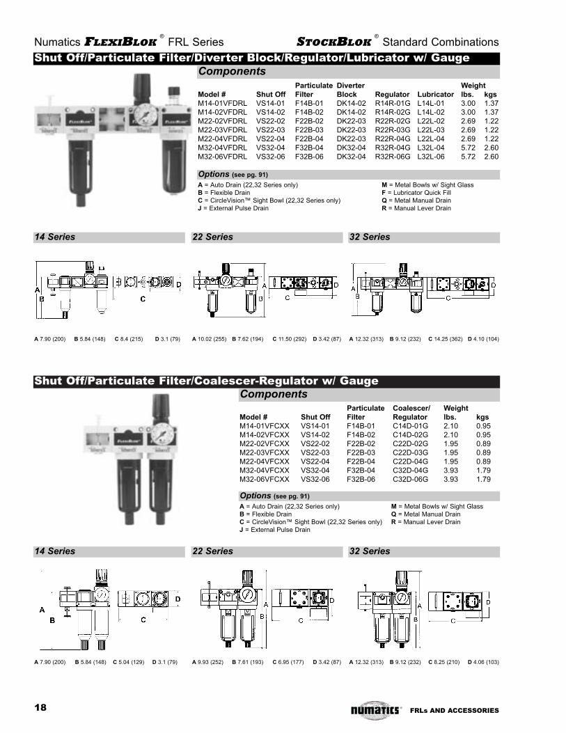
MODUBLOK ™ Combination models
The FLEXIBLOK ® modular system is designed to
connect individual components into a complete
assembly. Sometimes it is necessary to order an
assembly using additional or non-standard compo-
nents or combinations. The MODUBLOK™ system
makes it easy to order non-standard combinations.
As with all other components and combinations, all
modular assemblies come factory tested and
approved and assembled complete. For more
information on flow, dimensions, options, and
accessories, see individual component pages.
Because of the many possible combinations when
utilizing modular systems, it is recommended that
complex stations include a schematic drawing.
When ordering, specify all components at each
station, based on the example to the left.
How to label diverter blocks
When using a diverter block, indicate all units at
that station before continuing. If additional units
are mounted above the diverter block, use the let-
ter ‘T’ (for ‘top’) as well as a letter sequence (TA,
TB, TC, etc.) starting from the diverter block, and
continuing out. If units are placed below the divert-
er block, begin the two letter alphabetic sequence
with the letter ‘B’ (for bottom) as well as a letter
sequence (BA, BB, BC, etc.) starting with the
diverter block and continuing outward. Continue in
this pattern until all units are placed correctly.
About MODUBLOCK™ Assemblies
Numatics FLEXIBLOK®
FRL Series MODUBLOK®
Combination Models
NEED MORE PARTS AND INFORMATION?
• See page 9911 for more information on available
options and accessories.
• See page 110099 for information on ordering
replacement parts and repair kits.
Reducing Bushings
Reducing bushings may be required to connect
some components (i.e. pressure switches, etc).
Series Size
22 3/8 to 1/4 or 3/8 to 1/8
32 1/2 to 1/4 or 1/2 to 1/8
Example
MM OO DD 22 22 - 00 88
Station Description Model
Position Number
1 Shut-Off Valve VS22-03
2 Particulate Filter F22B-03
3 Coalescer w/ metal bowl and pulse drain F22D-03JM
4 Diverter Block DK22-03
4T Regulator R22R-03
4B Pressure Switch PS180CAN02
5 Regulator w/ gauge R22R-03G
6 Lubricator L22L-03
19FRLs AND ACCESSORIES

How to Order
Model:F = Filter
Series:14 = 1.5 oz bowl22 = 3.8 oz bowl32 = 8.5 oz bowl
Element:B = 5 micron
element
Threads:- = NPTFG = G tap (BSPP)R = PT (BSPT)
Port Size:01 = 1/8 (14 series only)02 = 1/4 (14 or 22 series only)03 = 3/8 (22 series only)04 = 1/2 (22 or 32 series only)06 = 3/4 (32 series only)
Options (see pg 101):A = auto drain (22 and 32 series)B = flexible drainC = CircleVision™ Sight Bowl (22 and 32 series)J = external pulse drainM = metal bowl with sight glassQ = metal manual drainR = manual lever drainU = ∆p indicator
PARTICULATE FILTER F14B, F22B, F32B Series
Primary air filters are designed to separate liquid, water, rust, pipe scale, and
debris from air lines. They should be installed upstream of the regulator
and/or lubricator to prevent contamination from reaching other components.
Water is removed mechanically by the deflector which causes the air to
move in a swirling motion. The condensed water droplets are then centrifu-
gally impounded upon the ID of the bowl then fall down past the quiet zone
baffle to the water sump. The air then passes through the sintered element
utilizing depth filtration and removes debris down to a 5 micron size.
Application
Features
Numatics FLEXIBLOK®
FRL Series
ANSI SYMBOL
Specifications
• Three convenient sizes
• 5 micron sintered elements standard
• Can be installed as modular or individual unit
• Includes screws and o-rings for modular connection
• Manual or automatic drain
• Polycarbonate bowl standard
• Optional metal bowl with sight glass
• Optional CircleVision™ sight bowl
• Bowl seal held captive (22 and 32 Series)
Polycarbonate CircleVision™ Metal
Bowl Bowl Bowl
Temperature Range (ºF) 40-120 40-120 40-120
Temperature Range (ºC) 4-50 4-50 4-50
Max. Pressure (PSIG) 150 250 200
Max. Pressure (BAR) 10 17 14
14 Series (Weight, lbs.) .60 - .65
14 Series (Weight, kg) .28 - .30
22 Series (Weight, lbs.) .65 .86 1.25
22 Series (Weight, kg) .30 .39 .57
32 Series (Weight, lbs.) 1.3 1.7 2.5
32 Series (Weight, kg) .59 .77 1.14
F32B-06 pictured
NEED MORE PARTS AND INFORMATION?
• See page 111199 for information on ordering replacement filters, bowls, etc.
• See page 110011 for more information on available options.
20
F 22 B - 04 AC
FRLs AND ACCESSORIES

Numatics FLEXIBLOK®
FRL Series Particulate Filter
DDiimmeennssiioonnss Dimensions in inches (millimeters in parenthesis)
14 Series Particulate
22 Series Particulate
32 Series Particulate
pre
ssu
re d
rop
air flow
FFllooww RRaatteessF14B-02 (5 micron particulate) F22B-04 (5 micron particulate) F32B-06 (5 micron particulate)
PPrroodduucctt CCrroossss SSeeccttiioonn
Maintenance Flush piping before installation. To maintain maxi-
mum efficiency of the filter and to avoid excessive pressure drop
the filter must be kept clean. On standard filters, open the drain
(turn counter-clockwise for standard drain models) periodically to
expel contents of bowl before it reaches the level of the lower baf-
fle.
Cleaning Removal from operation is not necessary to clean the
filter. Disassembly is simple and can be performed inline. Before
disassembling, shut off air supply and depressurize the filter.
Clean all parts (except the filter element) with household soap
and blow out filter body before reassembling.
Element Replacement Elements should be replaced after a
pressure drop of 10 PSID has been reached or after 1 year,
whichever occurs first.
NNootteess
21
pre
ssu
re d
rop
air flow
pre
ssu
re d
rop
air flow
MOUNTING HOLES
Ø.200 TYP.2
(Ø5.1)
MOUNTING HOLES
Ø.281 TYP.2
(Ø7.2)
FRLs AND ACCESSORIES

How to Order
Model:F = Filter
Series:14 = 1.5 oz bowl22 = 3.8 oz bowl32 = 8.5 oz bowl
Element:C = .7 micron
coarse coalescerD = .3 micron
fine coalescerE = .1 micron ultra
fine coalescerF = vapor adsorber
Threads:- = NPTFG = G tap (BSPP)R = PT (BSPT)
Port Size:01 = 1/8 (14 series only)02 = 1/4 (14 or 22 series only)03 = 3/8 (22 series only)04 = 1/2 (22 or 32 series only)06 = 3/4 (32 series only)
COALESCING FILTER F14, F22, F32 Series
The coalescing filter is utilized when either clean air is required or longer component life is desired.
This type of filter removes water and oil aerosols. It works differently than the particulate filter; dirty
air enters the element from the center and passes through a field of glass fibers which cause the
aerosols to form into droplets which are heavier than the surrounding air. The droplets grow larger
as they pass through the element and gravity causes the oil drops to drain to the sump of the bowl.
By removing the harmful oil varnishes and contaminant that attack seals and gaskets, the valve or
cylinder is much less likely to stick. To maximize the life of a coalescing filter it should always be
used after a 5 micron particulate filter or with the optional prefilter.
Application
Features
Numatics FLEXIBLOK®
FRL Series
ANSI SYMBOL
Specifications
• Three convenient sizes
• Cartridge element design
• Inner and outer support cores prevent element from crushing in either flow direction
• Available with manual or automatic drain
• Optional CircleVision™ sight bowl
• ∆p indicator standard on 14, 22, and 32 Series
Polycarbonate CircleVision™ Metal
Bowl Bowl Bowl
Temperature Range (ºF) 40-120 40-120 40-120
Temperature Range (ºC) 4-50 4-50 4-50
Max. Pressure (PSIG) 150 250 200
Max. Pressure (BAR) 10 17 14
14 Series (Weight, lbs.) .65 - .70
14 Series (Weight, kg) .30 - .32
22 Series (Weight, lbs.) .66 .89 1.28
22 Series (Weight, kg) .30 .40 .58
32 Series (Weight, lbs.) 1.42 1.83 2.56
32 Series (Weight, kg) .65 .83 1.16
F32D-06 pictured
C grade element, identified by its blue drain layer, is a coarse filter for large amounts of water,
rust, pipe scale, and liquid hydrocarbons. Excellent for environments that have severe contamina-
tion. Can be used for lubricated or ‘dry’ systems. Ideal for mainline filtration of plant air.
D grade element, identified by its green drain layer, is a fine filter for cylinders or valves - especial-
ly when the circuit is being run without lubrication (‘dry’). Excellent filter for desiccant or regenera-
tive style dryers.
E grade element, identified by its red drain layer, is an ultra fine filter for oil-free instrumentation
air, blow molding, food and drug packaging, electronics applications, and other applications requir-
ing maximum contamination removal.
F grade element, identified by its white drain layer, is an adsorbing filter that utilizes activated car-
bon to capture hydrobarbon vapor and deodorize compressed air. Typically it is used to protect
worker environments, food and drug applications, breathing air, and instrumentation for analytical
instruments. Life expectancy is approximately 3 months at rated flow. Adsorbers must be preceded
by a coalescer.
Recommended Uses
Prefilter Option - Suffix ‘D’Models using the C, D, or E grade elements can be equipped with an optional 3 micron internal
prefilter. The prefilter provides additional protection for the fine borosilicate fibers. Ideal for the
removal of high levels of solid contamination.
Options (see pg 101):A = auto drain (22 and 32 series)B = flexible drainC = CircleVision™ Sight Bowl (22 and 32 series)D = 3 micron, internal pleated prefilterJ = external pulse drainM = metal bowl with sight glassQ = metal manual drainR = manual lever drain
NEED MORE PARTS AND INFORMATION?
• See page 111199 for information on ordering replacement filters, bowls, etc.
• See page 110011 for more information on available options.
22
F 14 D - 02 AC
FRLs AND ACCESSORIES

Numatics FLEXIBLOK®
FRL Series Coalescing Filter
DDiimmeennssiioonnss Dimensions in inches (millimeters in parenthesis)
14 Series Coalescer
22 Series Coalescer
32 Series Coalescer
FFllooww RRaatteessF14D-02 (.3 micron coalescer) F22D-04 (.3 micron coalescer) F32D-06 (.3 micron coalescer)
PPrroodduucctt CCrroossss SSeeccttiioonn
Maintenance Flush piping before installation. To maintain maxi-
mum efficiency of the filter and to avoid excessive pressure drop
the filter must be kept clean. On standard filters, open the drain
(turn counter-clockwise for standard drain models) periodically to
expel contents of bowl before it reaches the bottom of the filter ele-
ment.
Cleaning Removal from operation is not necessary to clean the
filter. Disassembly is simple and can be performed inline. Before
disassembling, shut off air supply and depressurize the filter. Clean
all parts (except the filter element) with household soap and blow
out filter body before reassembling.
Element Replacement Elements should be replaced after a
pressure drop of 10 PSID has been reached or after 1 year,
whichever occurs first (adsorbers should be replaced every 3-6
months).
NNootteess
23
pre
ssu
re d
rop
air flow
pre
ssu
re d
rop
air flow
pre
ssu
re d
rop
air flow
MOUNTING HOLES
Ø.200 TYP.2
(Ø5.1)
MOUNTING HOLES
Ø.281 TYP.2
(Ø7.2)
FRLs AND ACCESSORIES

How to Order
Series:142232
Style:R = relievingN = non-relievingK = internal checkP = piston operator
Threads:- = NPTFG = G tap (BSPP)R = PT (BSPT)
Port Size:01 = 1/8 (14 series only)02 = 1/4 (14 or 22 series only)03 = 3/8 (22 series only)04 = 1/2 (22 or 32 series only)06 = 3/4 (32 series only)
Model:R = Regulator
REGULATOR R14, R22, R32 Series
Regulators are used to reduce pressure to a required working pressure. Utilizing opti-
mum pressure can save companies both component life and a hundreds or even thou-
sands of dollars in compressed air costs.
Regulators consist of a diaphragm which floats between a main spring (top) and a
valve (bottom). By turning the adjustment handle clockwise, the main spring is forced
onto the rubber diaphragm which, in turn, is pressed onto the valve stem. When the
spring pressure becomes greater than the air pressure in the control chamber below
the diaphragm, the valve is forced down and flow begins. As flow continues, the pres-
sure begins to build and air fills the control chamber, forcing the diaphragm upward. As
forces balance, the small spring under the valve piston causes the valve to close. The
cycle continues in a balanced process of reducing or increasing flow based upon the
downstream pressure.
Application
Features
Numatics FLEXIBLOK®
FRL Series
Specifications
• Three convenient sizes
• High flow in compact size
• Locking adjustment knob
• Four different pressure ratings available
• Relieving or non-relieving models
• Can be installed as modular or individual unit
• Standard output pressure 0-125 PSIG
14 Series 22 Series 32 Series
Temperature Range (ºF) 40-120 40-120 40-120
Temperature Range (ºC) 4-50 4-50 4-50
Max. Pressure (PSIG) 250 200 200
Max. Pressure (BAR) 17 14 14
Weight (lbs.) .65 .69 1.37
Weight (kg) .30 .31 .62
body material zinc aluminum aluminum
R32R-06 picturedPiston Operator - Style ‘P’The 14, 22, and 32 Series are offered with an optional Piston Operator. A Piston
Regulator will achieve extremely high cycle rates with limited wear. Ideal for applica-
tions where immediate flow is required. It is standard on the Internal Check Regulator.
Internal Check - Style ‘K’The 22 and 32 Series are offered with an optional internal check valve. This allows the
regulator to function between a valve and cylinder and not be damaged by the con-
stant change in direction of flow. Excellent for applications where multiple pressures
are required from one supply valve.
NEED MORE PARTS AND INFORMATION?
• See page 111199 for information on ordering replacement filters, bowls, etc.
• See page 110011 for more information on available options.
NOTE: All BSPP (G tap) and BSPT (R tap) models use BSPT gauge threads
24
R 32 R - 04 GP
FRLs AND ACCESSORIES
ANSI SYMBOL
(NON-RELIEVING)ANSI SYMBOL
(RELIEVING)
Options (see pg 101):G = gaugeH = 0-200 PSIG output
(22 or 32 Series)I = 0-25 PSIG outputL = 0-60 PSIG outputP = panel mount nutT = tamper resistant (14 or 22 Series)

Numatics FLEXIBLOK®
FRL Series Regulator
DDiimmeennssiioonnss Dimensions in inches (millimeters in parenthesis)
14 Series Regulator
22 Series Regulator
32 Series Regulator
FFllooww RRaatteess based on 100 PSIG (7 BAR) inlet
R14R-02 (14 Series Regulator) R22R-04 (22 Series Regulator) R32R-06 (32 Series Regulator)
PPrroodduucctt CCrroossss SSeeccttiioonn
Reduced Pressure Adjustment To adjust reduced pressure set-
tings, lift knob and turn (clockwise to increase pressure setting or
counter clockwise to lower setting). With relieving type regulators,
adjustment for lower reduced pressure follows adjustment of the
screw. With non-relieving regulators, adjustment for lower reduced
pressure will not be reached until the reduced pressure system is “bled
off” or until air flow starts.
Cleaning Erratic regulator operation or loss of regulation is almost
always due to dirt in the diaphragm area. To clean, shut off and depres-
surize the air line and disassemble the regulator. Clean parts with
household soap and blow out with compressed air. When reassem-
bling, make sure the disc assembly is firmly in place and the valve
stem fits into the center hole of the diaphragm assembly. Tighten cage
slightly more than “hand tight.”
NNootteess
1/8 gauge ports
1/8 gauge ports
25
air flow air flow air flow
1/4 gauge ports
MOUNTING HOLES
Ø.200 TYP.2
(Ø5.1)
MOUNTING HOLES
Ø.281 TYP.2
(Ø7.2)
FRLs AND ACCESSORIES
red
uc
ed
pre
ssu
re
red
uc
ed
pre
ssu
re
red
uc
ed
pre
ssu
re
26 FRLs AND ACCESSORIES
How to Order
Series:14
Style:R = relievingN = non-
relieving
Threads (all ports):- = NPTFG = G tap (BSPP)R = PT (BSPT)
Port Size:02 = 1/4
Options (see pg 101):G = gauge (0-160 std)P = panel mount nutT = tamper resistant
Model:MR =Manifold
Regulator
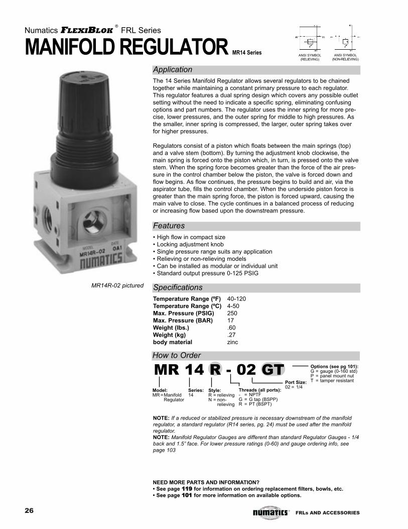
MANIFOLD REGULATOR MR14 Series
The 14 Series Manifold Regulator allows several regulators to be chained
together while maintaining a constant primary pressure to each regulator.
This regulator features a dual spring design which covers any possible outlet
setting without the need to indicate a specific spring, eliminating confusing
options and part numbers. The regulator uses the inner spring for more pre-
cise, lower pressures, and the outer spring for middle to high pressures. As
the smaller, inner spring is compressed, the larger, outer spring takes over
for higher pressures.
Regulators consist of a piston which floats between the main springs (top)
and a valve stem (bottom). By turning the adjustment knob clockwise, the
main spring is forced onto the piston which, in turn, is pressed onto the valve
stem. When the spring force becomes greater than the force of the air pres-
sure in the control chamber below the piston, the valve is forced down and
flow begins. As flow continues, the pressure begins to build and air, via the
aspirator tube, fills the control chamber. When the underside piston force is
greater than the main spring force, the piston is forced upward, causing the
main valve to close. The cycle continues in a balanced process of reducing
or increasing flow based upon the downstream pressure.
Application
Features
Numatics FLEXIBLOK®
FRL Series
ANSI SYMBOL
(NON-RELIEVING)
Specifications
• High flow in compact size
• Locking adjustment knob
• Single pressure range suits any application
• Relieving or non-relieving models
• Can be installed as modular or individual unit
• Standard output pressure 0-125 PSIG
Temperature Range (ºF) 40-120
Temperature Range (ºC) 4-50
Max. Pressure (PSIG) 250
Max. Pressure (BAR) 17
Weight (lbs.) .60
Weight (kg) .27
body material zinc
MR14R-02 pictured
NOTE: If a reduced or stabilized pressure is necessary downstream of the manifold
regulator, a standard regulator (R14 series, pg. 24) must be used after the manifold
regulator.
NOTE: Manifold Regulator Gauges are different than standard Regulator Gauges - 1/4
back and 1.5” face. For lower pressure ratings (0-60) and gauge ordering info, see
page 103
MR 14 R - 02 GT
NEED MORE PARTS AND INFORMATION?
• See page 111199 for information on ordering replacement filters, bowls, etc.
• See page 110011 for more information on available options.
ANSI SYMBOL
(RELIEVING)
27FRLs AND ACCESSORIES
MOUNTING HOLES
Ø.300 TYP.2 (Ø7.6)
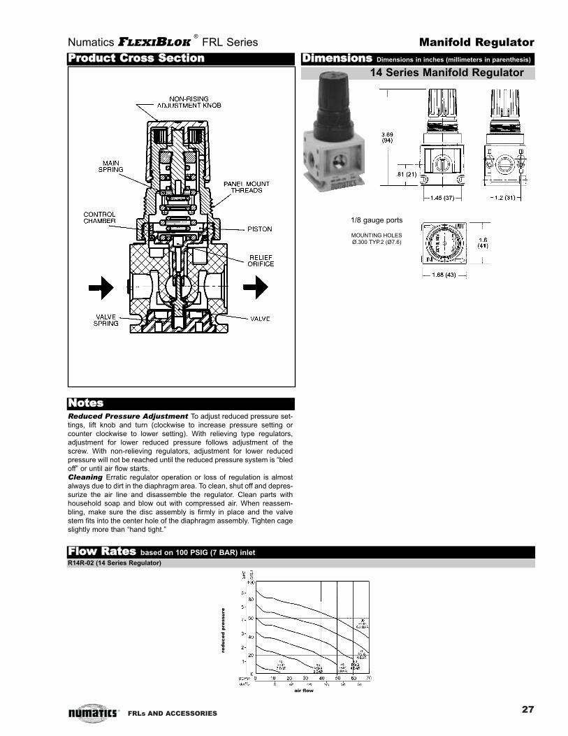
FFllooww RRaatteess based on 100 PSIG (7 BAR) inlet
R14R-02 (14 Series Regulator)
air flow
red
uc
ed
pre
ssu
re
Numatics FLEXIBLOK®
FRL Series Manifold Regulator
DDiimmeennssiioonnss Dimensions in inches (millimeters in parenthesis)
14 Series Manifold Regulator
PPrroodduucctt CCrroossss SSeeccttiioonn
Reduced Pressure Adjustment To adjust reduced pressure set-
tings, lift knob and turn (clockwise to increase pressure setting or
counter clockwise to lower setting). With relieving type regulators,
adjustment for lower reduced pressure follows adjustment of the
screw. With non-relieving regulators, adjustment for lower reduced
pressure will not be reached until the reduced pressure system is “bled
off” or until air flow starts.
Cleaning Erratic regulator operation or loss of regulation is almost
always due to dirt in the diaphragm area. To clean, shut off and depres-
surize the air line and disassemble the regulator. Clean parts with
household soap and blow out with compressed air. When reassem-
bling, make sure the disc assembly is firmly in place and the valve
stem fits into the center hole of the diaphragm assembly. Tighten cage
slightly more than “hand tight.”
NNootteess
1/8 gauge ports

28 FRLs AND ACCESSORIES
How to Order
Series:2232 Style:
W= all Pilot OperatedRegulators
Threads:- = NPTFG = G tap (BSPP)R = PT (BSPT) Port Size:
02 = 1/4 (22 series only)03 = 3/8 (22 series only)04 = 1/2 (22 or 32 series only)06 = 3/4 (32 series only)
Options (see pg 101):G = gaugeN = non-relieving
Model:R = Regulator
PILOT OPERATED REGULATOR R22W, R32W Series
Pilot Operated Regulators are adapted for control by a remote or dis-
tant small pilot regulator. These models are ideal for maximum
capacity requirements in applications where standard models would
not be readily accessible.
The regulator uses an 1/8 port located on the top of the unit to con-
nect from the ‘out’ port of a pilot regulator. Pressurizing of the pilot
port applies a force to the top diaphragm, causing the diaphragm
assembly to move downward, which in turn opens the main valve
and allows air flow across the seat area. Downstream pressure is
sensed by the lower diaphragm and, when it equals or exceeds the
force applied to the upper diaphragm, shifts the diaphragm assembly
upward, causing the main valve to seat and revert to a no-flow condi-
tion.
Application
Features
Numatics FLEXIBLOK®
FRL Series
ANSI SYMBOL
Specifications
• Two convenient sizes
• High flow
• Relieving or non-relieving models
• Reduced pressure within 5-7 PSIG of pilot pressure
• Modular with the rest of the FLEXIBLOK ® system
22 Series 32 Series
Temperature Range (ºF) 40-120 40-120
Temperature Range (ºC) 4-50 4-50
Min. Pilot Pressure (PSI) 15 15
Min. Pilot Pressure (BAR) 1 1
Max. Pilot Pressure (PSI) 150 150
Max. Pilot Pressure (BAR) 10.2 10.2
Max. Supply Pressure (PSI) 150 150
Max. Supply Pressure (BAR) 10.2 10.2
Weight (lbs.) .66 1.35
Weight (kg) .25 .50
body material aluminum aluminum
R32W-04 pictured
NEED MORE PARTS AND INFORMATION?
• See page 111199 for information on ordering replacement filters, bowls, etc.
• See page 110011 for more information on available options.
NOTE: All BSPP (G tap) and BSPT (R tap) models use BSPT gauge threads
R 32 W - 04 G

29FRLs AND ACCESSORIES
Numatics FLEXIBLOK®
FRL Series Pilot Operated Regulator
DDiimmeennssiioonnss Dimensions in inches (millimeters in parenthesis)
22 Series Pilot Operated Regulator
32 Series Pilot Operated Regulator
FFllooww RRaatteess based on 100 PSIG (7 BAR) inlet
R22W-04 (22 Series Pilot Operated Regulator) R32W-06 (32 Series Pilot Operated Regulator)
PPrroodduucctt CCrroossss SSeeccttiioonn
Installation The springs and bonnet of the regulators are
replaced by a pilot diaphragm assembly that operates the main
diaphragm assembly by moving a connecting bushing. A
remote regulator is connected to the pilot port to control the pilot
regulator.
Cleaning Erratic regulator operation or loss of regulation is
almost always due to dirt in the diaphragm area. To clean, shut
off and depressurize the air line and disassemble the regulator.
Clean parts with household soap and blow out with com-
pressed air. When reassembling, make sure the lower
diaphragm disc assembly is firmly in place and the valve stem
fits into the center hole of the diaphragm assembly. Tighten the
four screws on the top of the regulator “hand tight”.
NNootteess
red
uc
ed
pre
ssu
re
air flow
1/4 gauge ports
red
uc
ed
pre
ssu
re
air flow
1/8 gauge ports
MOUNTING HOLES
Ø.200 TYP.2
(Ø5.1)
MOUNTING HOLES
Ø.281 TYP.2
(Ø7.2)

30 FRLs AND ACCESSORIES
How to Order
Model:P = Particulate/
Regulator
Series:14 = 1.5 oz bowl22 = 3.8 oz bowl32 = 8.5 oz bowl
Element:B = 5 micron element
Threads:- = NPTFG = G tap (BSPP)R = PT (BSPT)
Port Size:01 = 1/8 (14 series only)02 = 1/4 (14 or 22 series only)03 = 3/8 (22 series only)04 = 1/2 (22 or 32 series only)06 = 3/4 (32 series only)
Options (see pg 101):A* = auto drain (22 and 32 series)B = flexible drainC = CircleVision™ Sight Bowl (22 and 32 series)G = gaugeH* = 0-200 PSIG outputI = 0-25 PSIG outputJ = external pulse drainL = 0-60 PSIG outputM = metal bowl with sight glassN = non-relievingP = panel mount nutQ = metal manual drainR = manual lever drainT = tamper resistant (14 or 22 Series)
* = ‘A’ and ‘H’ options cannot be used together
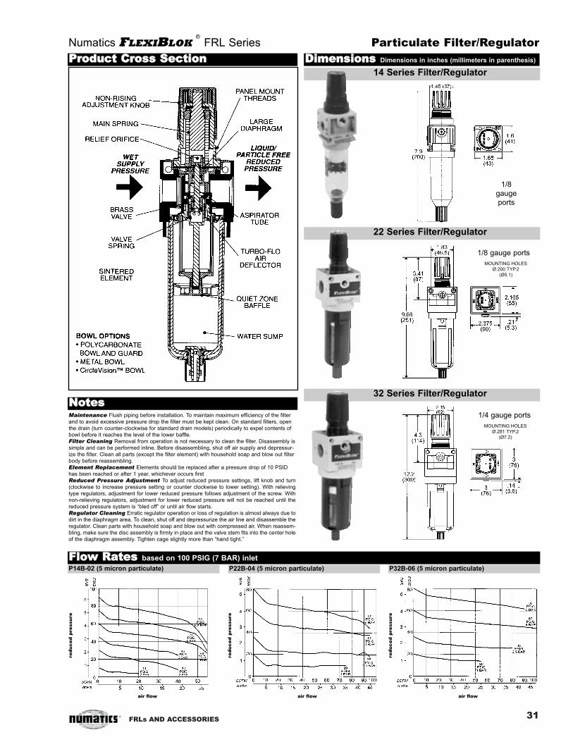
PARTICULATEFILTER/REGULATORP14B, P22B, P32B Series
The integral part of the filter/regulator (‘piggyback’) is a two station
component designed to filter and regulate compressed air when cost
and space are of primary concern. As wet, dirty air enters, it immedi-
ately flows through the air deflector, causing the air to move in a
swirling motion. After condensed water is centrifugally removed, air
passes through the filter and into the regulator. The air pressure is
systematically reduced and exits the housing as clean, dry air that is
ready to work at the specified pressure.
NOTE: see separate filter (pg. 20) and regulator (pg. 24) pages for
additional information.
Application
Features
Numatics FLEXIBLOK®
FRL Series
ANSI SYMBOL
Specifications
• Three convenient sizes
• 5 micron element standard
• Can be installed as individual or modular unit
• Non-rising knob
• Optional CircleVision™ sight bowl
• Optional metal bowl with sight glass
• Standard output pressure 0-125 PSIG
• Bowl seal held captive (22 and 32 Series)
Polycarbonate CircleVision™ Metal (Zinc) bowl
Bowl Bowl w/ Sight Glass
Temperature Range (ºF) 40-120 40-120 40-120
Temperature Range (ºC) 4-50 4-50 4-50
Max. Pressure (PSIG) 150 250 200
Max. Pressure (BAR) 10 17 14
14 Series (Weight, lbs.) .75 - .80
14 Series (Weight, kg) .34 - .37
22 Series (Weight, lbs.) .91 1.2 1.5
22 Series (Weight, kg) .41 .55 .68
32 Series (Weight, lbs.) 1.81 2.34 2.94
32 Series (Weight, kg) .82 1.06 1.34
P32B-06 pictured
NEED MORE PARTS AND INFORMATION?
• See page 111199 for information on ordering replacement filters, bowls, etc.
• See page 110011 for more information on available options.
NOTE: All BSPP (G tap) and BSPT (R tap) models use BSPT gauge threads
NOTE: To order a piston style filter/regulator, add ‘P’ to the model number
(i.e. P32BP-02GIP)
P 14 B - 02 GIP
31FRLs AND ACCESSORIES
Numatics FLEXIBLOK®
FRL Series Particulate Filter/Regulator
DDiimmeennssiioonnss Dimensions in inches (millimeters in parenthesis)
14 Series Filter/Regulator
22 Series Filter/Regulator
32 Series Filter/Regulator
FFllooww RRaatteess based on 100 PSIG (7 BAR) inlet
P14B-02 (5 micron particulate) P22B-04 (5 micron particulate) P32B-06 (5 micron particulate)
PPrroodduucctt CCrroossss SSeeccttiioonn
Maintenance Flush piping before installation. To maintain maximum efficiency of the filter
and to avoid excessive pressure drop the filter must be kept clean. On standard filters, open
the drain (turn counter-clockwise for standard drain models) periodically to expel contents of
bowl before it reaches the level of the lower baffle.
Filter Cleaning Removal from operation is not necessary to clean the filter. Disassembly is
simple and can be performed inline. Before disassembling, shut off air supply and depressur-
ize the filter. Clean all parts (except the filter element) with household soap and blow out filter
body before reassembling.
Element Replacement Elements should be replaced after a pressure drop of 10 PSID
has been reached or after 1 year, whichever occurs first
Reduced Pressure Adjustment To adjust reduced pressure settings, lift knob and turn
(clockwise to increase pressure setting or counter clockwise to lower setting). With relieving
type regulators, adjustment for lower reduced pressure follows adjustment of the screw. With
non-relieving regulators, adjustment for lower reduced pressure will not be reached until the
reduced pressure system is “bled off” or until air flow starts.
Regulator Cleaning Erratic regulator operation or loss of regulation is almost always due to
dirt in the diaphragm area. To clean, shut off and depressurize the air line and disassemble the
regulator. Clean parts with household soap and blow out with compressed air. When reassem-
bling, make sure the disc assembly is firmly in place and the valve stem fits into the center hole
of the diaphragm assembly. Tighten cage slightly more than “hand tight.”
NNootteess
1/8
gauge
ports
air flow air flow air flow
1/4 gauge ports
1/8 gauge ports
MOUNTING HOLES
Ø.200 TYP.2
(Ø5.1)
MOUNTING HOLES
Ø.281 TYP.2
(Ø7.2)
red
uc
ed
pre
ssu
re
red
uc
ed
pre
ssu
re
red
uc
ed
pre
ssu
re

32 FRLs AND ACCESSORIES
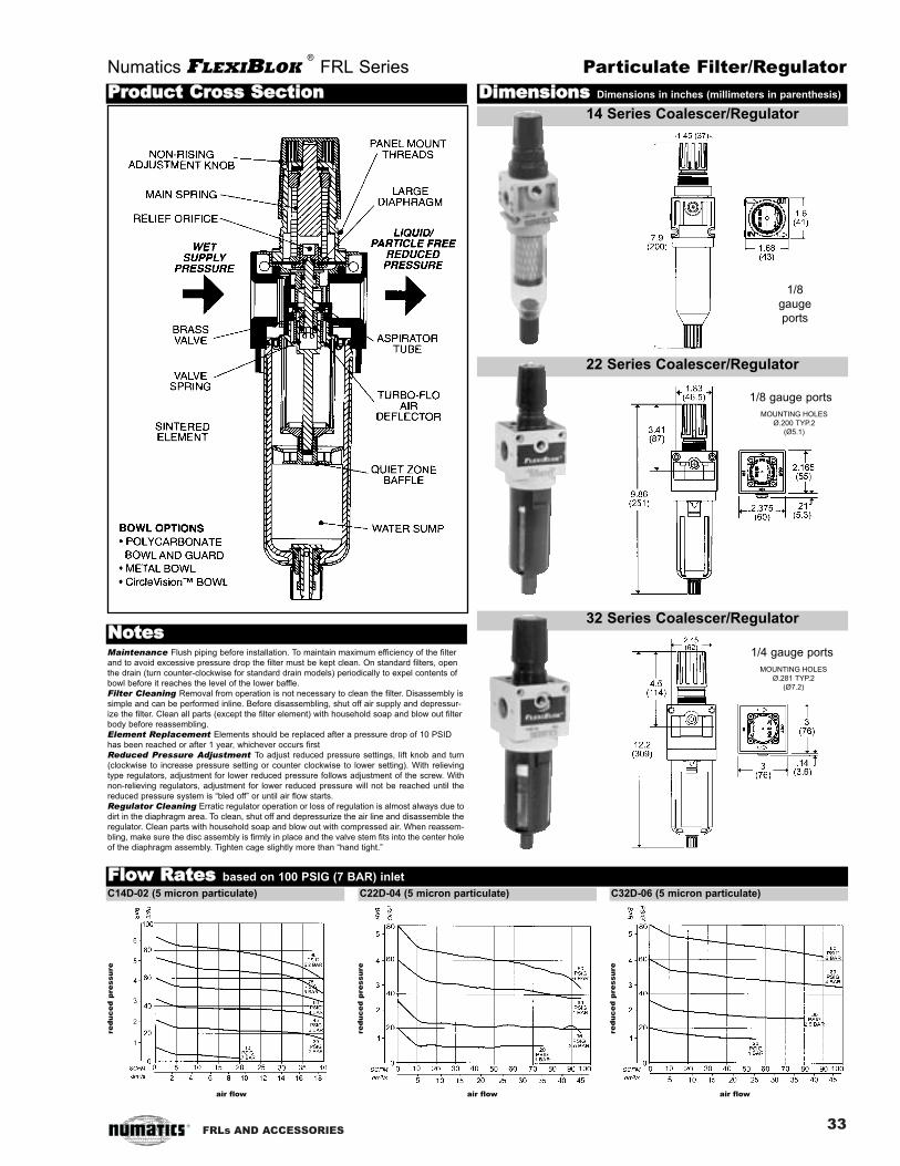
COALESCINGFILTER/REGULATORC14D, C22D, C32D Series
Numatics FLEXIBLOK®
FRL Series
ANSI SYMBOL
NEED MORE PARTS AND INFORMATION?
• See page 111199 for information on ordering replacement filters, bowls, etc.
• See page 110011 for more information on available options.
How to Order
Application
Features
Specifications
• Cartridge element design
• Inner/outer support cores prevent element from crushing in either flow direction
• Connects easily to FLEXIBLOK ® Modular system
• Four element grades available
Polycarbonate CircleVision™ Metal (Zinc) bowl
Bowl Bowl w/ Sight Glass
Temperature Range (ºF) 40-120 40-120 40-120
Temperature Range (ºC) 4-50 4-50 4-50
Max. Pressure (PSIG) 150 250 200
Max. Pressure (BAR) 10 17 14
14 Series (Weight, lbs.) .80 N/A .85
14 Series (Weight, kg) .35 N/A .38
22 Series (Weight, lbs.) .92 1.2 1.6
22 Series (Weight, kg) .42 .55 .73
32 Series (Weight, lbs.) 1.82 2.35 2.95
32 Series (Weight, kg) .83 1.07 1.34
Model:C = Coalescer/
Regulator
Threads:- = NPTFG = G tap (BSPP)R = PT (BSPT)
Element:C = .7 micron coarse coalescerD = .3 micron fine coalescerE = .1 micron ultra fine coalescerF = vapor adsorber
The Numatics C Series Coalescer/Regulator is a two station point of use air preparation systemdesigned to provide superior filtration and regulation in one compact housing.
The C Series combines a multiple support cartridge style borosilicate glass element with a pilot bal-anced regulator to assure the maximum performance of downstream components.
Available with four different element grade choices, the C Series Coalescer/Regulator can be outfit-ted to attack and remove the exact type of contamination that is critical to a specific application.
C32D-06 pictured
Options (see pg 101):A* = auto drain (22 and 32 only)B = flexible drainC = CircleVision™ sight bowlD = 3 micron, internal pleated prefilterG = gaugeH* = 0-200 PSIG outputI = 0-25 PSIG outputJ = external pulse drainL = 0-60 PSIG outputM = metal bowl with sight glassN = non-relievingP = panel mount nutQ = metal manual drainR = manual lever drainT = tamper-resistant (14 and 22 only)* = ‘A’ and ‘H’ options cannot be used together
NOTE: All BSPP (G tap) and BSPT (R tap) models use BSPT gauge threads
C grade element, identified by its blue drain layer, is a coarse filter for large amounts of water,
rust, pipe scale, and liquid hydrocarbons. Excellent for environments that have severe contamina-
tion. Can be used for lubricated or ‘dry’ systems. Ideal for mainline filtration of plant air.
D grade element, identified by its green drain layer, is a fine filter for cylinder or valves - especially
when the circuit is being run without lubrication (‘dry’). Excellent filter for desiccant or regenerative
style dryers.
E grade element, identified by its red drain layer, is an ultra fine filter for oil-free instrumentation
air, blow molding, food and drug packaging, electronics applications, and other applications requir-
ing maximum contamination removal.
F grade element, identified by its white drain layer, is an adsorbing filter that utilizes activated car-
bon to capture hydrocarbon vapor and deodorize compressed air. Typically it is used to protect
worker environments, food and drug applications, breathing air, and instrumentation for analytical
instruments. Life expectancy is approximately 3 months at rated flow.
Recommended Uses
Prefilter Option - Suffix ‘D’Models using the C, D, or E grade elements can be equipped with an optional 3 micron internal
prefilter. The prefilter provides additional protection for the fine borosilicate fibers. Ideal for the
removal of high levels of solid contamination.
C 32 C - 06 AGNQ
Series:12 = 1.5 oz. bowl22 = 3.8 oz. bowl32 = 8.5 oz. bowl
Port Size:01 = 1/802 = 1/403 = 3/804 = 1/206 = 3/4
33FRLs AND ACCESSORIES
Numatics FLEXIBLOK®
FRL Series Particulate Filter/Regulator
DDiimmeennssiioonnss Dimensions in inches (millimeters in parenthesis)
14 Series Coalescer/Regulator
22 Series Coalescer/Regulator
32 Series Coalescer/Regulator
FFllooww RRaatteess based on 100 PSIG (7 BAR) inlet
C14D-02 (5 micron particulate) C22D-04 (5 micron particulate) C32D-06 (5 micron particulate)
PPrroodduucctt CCrroossss SSeeccttiioonn
Maintenance Flush piping before installation. To maintain maximum efficiency of the filter
and to avoid excessive pressure drop the filter must be kept clean. On standard filters, open
the drain (turn counter-clockwise for standard drain models) periodically to expel contents of
bowl before it reaches the level of the lower baffle.
Filter Cleaning Removal from operation is not necessary to clean the filter. Disassembly is
simple and can be performed inline. Before disassembling, shut off air supply and depressur-
ize the filter. Clean all parts (except the filter element) with household soap and blow out filter
body before reassembling.
Element Replacement Elements should be replaced after a pressure drop of 10 PSID
has been reached or after 1 year, whichever occurs first
Reduced Pressure Adjustment To adjust reduced pressure settings, lift knob and turn
(clockwise to increase pressure setting or counter clockwise to lower setting). With relieving
type regulators, adjustment for lower reduced pressure follows adjustment of the screw. With
non-relieving regulators, adjustment for lower reduced pressure will not be reached until the
reduced pressure system is “bled off” or until air flow starts.
Regulator Cleaning Erratic regulator operation or loss of regulation is almost always due to
dirt in the diaphragm area. To clean, shut off and depressurize the air line and disassemble the
regulator. Clean parts with household soap and blow out with compressed air. When reassem-
bling, make sure the disc assembly is firmly in place and the valve stem fits into the center hole
of the diaphragm assembly. Tighten cage slightly more than “hand tight.”
NNootteess
1/8
gauge
ports
air flow air flow air flow
1/4 gauge ports
1/8 gauge ports
MOUNTING HOLES
Ø.200 TYP.2
(Ø5.1)
MOUNTING HOLES
Ø.281 TYP.2
(Ø7.2)
red
uc
ed
pre
ssu
re
red
uc
ed
pre
ssu
re
red
uc
ed
pre
ssu
re

34 FRLs AND ACCESSORIES
The proper lubrication of air tools, valves, cylinders, motors, etc. requires the use of an oil that isspecifically recommended for use in air line lubricators. An air line lubricant is often subjected tovery adverse conditions - high temperatures, dirty air, and oxidation caused by flowing air are just afew. Pneumatic devices are likely subjected to these same conditions in addition to sitting idle forlong periods of time. Unless the oil has superior oxidation stability and high film strength, it willblow off the surfaces to be oiled leaving a tacky residue known as ‘varnish’.
An important criterion is viscosity. If an oil is too heavy, it will not be atomized and carried down-stream to the component requiring lubrication. Often it will reclassify in the pipe. While it is impossi-ble to guarantee the success of any lubricating oil because of the variables, oils having the follow-ing characteristics usually perform quite well:
• Viscosity: 100-150 SUS at 100ºF• High viscosity index: over 90• Superior oxidation stability as determined by ASTM test D943: over 2000• Anti-foaming• High film strength• Compatible with Buna N rubber• Aniline range: 180-210
A lubricant that works well is Mobil D.T.E.® Light Lubricating Oil from Mobil Chemical company.This oil meets all of the foregoing specifications. Many other good lubricants are available. Consultyour Numatics representative for his recommendations.
How to Order
Series:14 = 1.5 oz. bowl22 = 3.8 oz. bowl32 = 8.5 oz. bowl
Style:L = Standard
Lubricators
Threads:- = NPTFG = G tap (BSPP)R = PT (BSPT)
Port Size:01 = 1/8 (14 series only)02 = 1/4 (14 or 22 series only)03 = 3/8 (22 series only)04 = 1/2 (22 or 32 series only)06 = 3/4 (32 series only)
Options (see pg 101):C = CircleVision™ sight bowl
(22 and 32 Series only)F = button head fillK = drain on bowlM = metal bowl with sight glass
Model:L = Lubricator
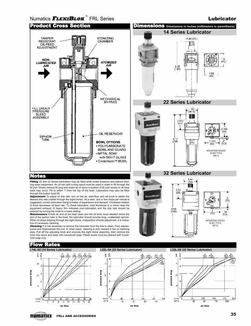
LUBRICATOR L14L, L22L, L32L Series
Usually mounted third in the FRL Series, the lubricator is designed to inject oil aerosols into the
airstream of a pneumatic circuit. As air flows from the regulator, some air is diverted from the main
orifice and is allowed to flow through the fill under pressure bleed assembly and pressurize the
bowl. This forces oil up the siphon tube past a flow check and into the integral valve/sight dome.
The oil film then drops through the valve and into the atomization chamber at a rate that is auto-
matically proportional to the air flow. This virtually eliminates the need for readjustment. The
Numatics lubricator can begin delivering lubrication at flows less than 2 SCFM.
Application
Features
Numatics FLEXIBLOK®
FRL Series
ANSI SYMBOL
Specifications
• Three convenient sizes
• Lubrication to begin at less than 2 SCFM
• Can be filled under pressure (22 and 32 series only)
• Tamper-resistant knob standard
• Optional CircleVision™ sight bowl
• Optional metal bowl with sight glass
• Can be mounted as individual or modular unit
• Button head fill optional on all sizes
• Atomizing chamber develops longer life aerosols
14 Series 22 Series 32 Series
Temperature Range (ºF) 40-120 40-120 40-120
Temperature Range (ºC) 4-50 4-50 4-50
Max. Pressure (PSIG) 200 200 200
Max. Pressure (BAR) 14 14 14
Weight (lbs.) .60 .69 1.37
Weight (kg) .27 .31 .62
body material zinc aluminum aluminum
L32L-04 pictured
Finding the Proper Lubricant
NEED MORE PARTS AND INFORMATION?
• See page 111199 for information on ordering replacement filters, bowls, etc.
• See page 110011 for more information on available options.
L 22 L - 02 CF
35FRLs AND ACCESSORIES
Numatics FLEXIBLOK®
FRL Series Lubricator
DDiimmeennssiioonnss Dimensions in inches (millimeters in parenthesis)
14 Series Lubricator
22 Series Lubricator
32 Series Lubricator
FFllooww RRaatteessL14L-02 (14 Series Lubricator) L22L-04 (22 Series Lubricator) L32L-06 (32 Series Lubricator)
PPrroodduucctt CCrroossss SSeeccttiioonn
Filling 22 and 32 Series lubricators may be filled while under pressure and without shut-
ting down equipment. An oil can with a long spout must be used in order to fill through the
fill port. Slowly remove fill plug and insert tip of spout to bottom of fill port recess or oil blow
back may occur. Fill to within 1” from the top of the bowl. Lubricators may also be filled
through the button head fill.
Adjustment To adjust oil drip rate, turn on the air, start flow, and set knob to obtain the
desired drip rate (visible through the sight dome). As a start, one or two drops per minute is
suggested, correct lubrication being a matter of experience and demand. Clockwise rotation
of knob decreases oil feed rate. To check lubrication, hold thumbnail or a mirror near the
equipment exhaust. A heavy film indicates over-lubrication and the drip rate should be
reduced by turning the knob to a lower setting.
Maintenance If both air and oil are kept clean and the oil level never allowed below the
end of the siphon tube in the bowl, the lubricator should provide long, unattended service.
When oil stops dripping through the sight dome, irrespective of knob adjustment, it is indica-
tive of necessary cleaning.
Cleaning It is not necessary to remove the lubricator from the line to clean. First, depres-
surize and disassemble the unit. In most cases, cleaning is only needed in the oil metering
area. Pull off the adjusting knob and unscrew the sight dome assembly, then remove the
inner drip spout and clean with household soap. Plastic bowls must be cleaned with house-
hold soap only.
NNootteess
pre
ssu
re d
rop
air flow
pre
ssu
re d
rop
air flow
pre
ssu
re d
rop
air flow
MOUNTING HOLES
Ø.200 TYP.2
(Ø5.1)
MOUNTING HOLES
Ø.281 TYP.2
(Ø7.2)

36 FRLs AND ACCESSORIES
How to Order
Series:2232
Style:C = Standard
Solenoid Soft Start
Threads:- = NPTFG = G tap (BSPP)R = PT (BSPT)
Port Size:02 = 1/4 (22 only)03 = 3/8 (22 only)04 = 1/2 (22/32)06 = 3/4 (32 only)
Options (see pg 101):B = standard solenoidE = 110V AC 50/60 HzF = 230V AC 50/60 HzJ = 24V AC 50/60 Hz coilK = 24V DC coilL = plug with lightP = standard black plug ass’yM = mufflerN = no manual overrideG = gauge
Model:S = Solenoid
Soft Start
SOLENOID SOFT START QUICKEXHAUST VALVE S22C, S32C Series
The S22C and S32C valves combine the gradual filling feature of an
auto pilot soft start with the added features of a solenoid quick
exhaust valve. Upon energizing the solenoid, pilot pressure is applied
to the top of the spool, shifting the spool downward and closing the
exhaust port. Pilot pressure is also applied to the shuttle valve, open-
ing it, and allowing supply air to be metered downstream through the
metering valve. When downstream pressure reaches approximately
60% of supply pressure, the spool opens the main valve, allowing full
flow. When the solenoid is de-energized pilot pressure is removed,
causing the spool to retract and opening the exhaust port.
Downstream pressure then exhausts through the exhaust port. The
shuttle valve also reseats, cutting off supply pressure.
Application
Features
Numatics FLEXIBLOK®
FRL Series
ANSI SYMBOL
Specifications
• Two convenient sizes
• Lockout feature prevents unauthorized pressurization of system
• High exhaust capacity for quick depletion of pressure
• High inlet to outlet flow capability
• Connects easily to FLEXIBLOK ® Modular system
• Incorporated metering valve controls how quickly downstream
pressure is reached, which controls the slow start feature
22 Series Exhaust Ports (NPTF): 1/2
32 Series Exhaust Ports (NPTF): 1/2
22 Series Gauge Ports (NPTF): 1/8
32 Series Gauge Ports (NPTF): 1/4
Temperature Range (ºF): 40-120
Temperature Range (ºC): 4-50
Min. Pressure (PSIG): 60
Min. Pressure (BAR): 4
Max. Pressure (PSIG): 150
Max. Pressure (BAR): 10
22 Series Weight, lbs. (kg.): .94 (.43)
32 Series Weight, lbs. (kg.): 1.56 (.71)
S32C-04BELM pictured
Cv in-out/out-exh (22 Series, 1/4): 2 / 1.2
Cv in-out/out-exh (22 Series, 3/8): 2.87 / 1.38
Cv in-out/out-exh (22 Series, 1/2): 3.62 / 1.32
Cv in-out/out-exh (32 Series, 1/2): 5.24 / 3.01
Cv in-out/out-exh (32 Series, 3/4): 6.47 / 3.14
body material: aluminum
Wattage & Amperage:
110V AC: 1.42 watts / .022 amps
230V AC: 2.0 watts / .016 amps
24V AC: 2.0 watts / 0.011 amps
24V DC:2.0 watts / 0.08 amps
NEED MORE PARTS AND INFORMATION?
• See page 111199 for information on ordering replacement filters, bowls, etc.
• See page 110011 for more information on available options.
NOTE: All BSPP (G tap) and BSPT (R tap) models use BSPT gauge threads
S 32 C - 06 BFGLM

37FRLs AND ACCESSORIES
Numatics FLEXIBLOK®
FRL Series Solenoid Soft Start Quick Exhaust Valve
DDiimmeennssiioonnss Dimensions in inches (millimeters in parenthesis)
22 Series Solenoid Soft Start
32 Series Solenoid Soft Start
FFllooww RRaatteess
PPrroodduucctt CCrroossss SSeeccttiioonn
Disassembly We do not recommend the disassem-
bly of the Solenoid Soft Start outside of the factory
except by trained, qualified individuals. There are no
serviceable components inside the unit.
Maintenance The only serviceable components are
located outside of the unit; the muffler (if equipped), the
solenoid, and the plug. These components may be
replaced if necessary (Please see the ‘Options and
Accessories’ and ‘Service Kits’ sections on pages 93
and 107, respectively).
NNootteess
S22C-04B (22 Series Solenoid Soft Start Quick Exhaust Valve) S32C-06B (32 Series Solenoid Soft Start Quick Exhaust Valve)
pre
ssu
re d
rop
air flow
pre
ssu
re d
rop
air flow
1/4 gauge ports
1/8 gauge ports
MOUNTING HOLES
Ø.200 TYP.2
(Ø5.1)
MOUNTING HOLES
Ø.281 TYP.2
(Ø7.2)

FRLs AND ACCESSORIES
How to Order
Series:2232
Style:E = Standard
Solenoid QuickExhaust Valve
Threads:- = NPTFG = G tap (BSPP)R = PT (BSPT)
Port Size:02 = 1/4 (22 only)03 = 3/8 (22 only)04 = 1/2 (22/32)06 = 3/4 (32 only)
Options (see pg 101):B = standard solenoidE = 110V AC 50/60 HzF = 230V AC 50/60 HzJ = 24V AC 50/60 Hz coilK = 24V DC coilL = plug with lightP = standard black plug ass’yM = mufflerN = no manual overrideG = gauge
Model:S = Solenoid
QuickExhaust
SOLENOIDQUICK EXHAUSTVALVES22E, S32E Series
The S22E and S32E Solenoid Quick Exhaust Valves are high flow,
high exhaust, normally closed, 3-ported, 2-position directional control
shut-off valves which increases safety for machine operators. When
the solenoid is energized, inlet air is applied to the top of the spool.
The spool shifts downward, sealing the exhaust port and pushing
down and opening the main valve, allowing full flow downstream.
When the solenoid is de-energized, air is cut from the spool, allowing
the springs to retract and the spool and main valve to return to their
normally closed positions, thus rapidly exhausting all downstream air.
The bottom exhaust port is tapped to allow for muffler installation.
Application
Features
Numatics FLEXIBLOK®
FRL Series
ANSI SYMBOL
Specifications
• Two convenient sizes
• Lockout feature (located in slide valve) prevents unauthorized
pressurization of system
• Standard manual override (or with no manual override option)
• Low-wattage coil prevents high-temperatures
• High exhaust capacity for quick depletion of pressure
• High inlet to outlet flow capability
• Connects easily to FLEXIBLOK ® Modular system
22 Series Exhaust Ports (NPTF): 1/2
32 Series Exhaust Ports (NPTF): 1/2
22 Series Gauge Ports (NPTF): 1/8
32 Series Gauge Ports (NPTF): 1/4
Temperature Range (ºF): 40-120
Temperature Range (ºC): 4-50
Min. Operating Pressure (PSIG): 35
Min. Operating Pressure (BAR): 2.45
Max. Operating Pressure (PSIG): 150
Max. Operating Pressure (BAR): 10
22 Series Weight, lbs. (kg.): 1.15 (.53)
32 Series Weight, lbs. (kg.): 1.75 (.79)
S32E-04BELM pictured
Cv in-out/out-exh (22 Series, 1/4): 2 / 1.2
Cv in-out/out-exh (22 Series, 3/8): 2.87 / 1.38
Cv in-out/out-exh (22 Series, 1/2): 3.62 / 1.32
Cv in-out/out-exh (32 Series, 1/2): 5.24 / 3.01
Cv in-out/out-exh (32 Series, 3/4): 6.47 / 3.14
Body material: Aluminum
Wattage & Amperage:
110V AC: 1.42 watts / .022 amps
230V AC: 2.0 watts / .016 amps
24V AC: 2.0 watts / 0.011 amps
24V DC:2.0 watts / 0.08 amps
NEED MORE PARTS AND INFORMATION?
• See page 111199 for information on ordering replacement filters, bowls, etc.
• See page 110011 for more information on available options.
NOTE: All BSPP (G tap) and BSPT (R tap) models use BSPT gauge threads
S 32 E - 04 BFGLM
38

FRLs AND ACCESSORIES
Numatics FLEXIBLOK®
FRL Series Solenoid Quick Exhaust Valve
DDiimmeennssiioonnss Dimensions in inches (millimeters in parenthesis)
22 Series Solenoid Quick Exhaust
32 Series Solenoid Quick Exhaust
FFllooww RRaatteess
PPrroodduucctt CCrroossss SSeeccttiioonn
Disassembly We do not recommend the disassem-
bly of the Solenoid Quick Exhaust outside of the facto-
ry except by trained, qualified individuals. There are no
serviceable components inside the unit.
Maintenance The only serviceable components are
located outside of the unit; the muffler (if equipped), the
solenoid, and the plug. These components may be
replaced if necessary (Please see the ‘Options and
Accessories’ and ‘Service Kits’ sections on pages 93
and 107, respectively).
NNootteess
S22E-04B (22 Series Solenoid Soft Start Quick Exhaust Valve) S32E-06B (32 Series Solenoid Soft Start Quick Exhaust Valve)
pre
ssu
re d
rop
air flow
pre
ssu
re d
rop
air flow
1/4 gauge ports
1/8 gauge ports
MOUNTING HOLES
Ø.200 TYP.2
(Ø5.1)
MOUNTING HOLES
Ø.281 TYP.2
(Ø7.2)
39

40 FRLs AND ACCESSORIES
12 VS14-01 VS14G01 VS14R01 1.63 (41) 1.6 (41) 1.6 (41) 3 (76) 1/8
VS14-02 VS14G02 VS14R02 1.63 (41) 1.6 (41) 1.6 (41) 3 (76) 1/4
22 VS22-02 VS22G02 VS22R02 2.0 (50) 2.16 (55) 1.86 (47) 3.1 (79) 1/4
VS22-03 VS22G03 VS22R03 2.0 (50) 2.16 (55) 1.86 (47) 3.1 (79) 3/8
VS22-04 VS22G04 VS22R04 2.0 (50) 2.16 (55) 1.86 (47) 3.1 (79) 1/2
32 VS32-04 VS32G04 VS32R04 2.25 (57) 3.0 (76) 2.57 (65) 4.2 (107)1/2
VS32-06 VS32G06 VS32R06 2.25 (57) 3.0 (76) 2.57 (65) 4.2 (107)3/4
Designed to give FLEXIBLOK ® com-
ponents total versatility, the diverter
block mounts directly inline with the
FRL combination. Additional compo-
nents can then be manifold mounted
in a compact manner that doesn’t
cause excessive pressure drop.
There are two available ports per
unit; both are tapped for standard
service.
Max. inlet pressure: 200 PSI (13.7
bar)
12 DK14-02 DK14G02 DK14R02 1.72 1.54 1.6 1/4 1/8 Tapped 1/4 NPTF In & Out
(44) (39) (41) with two 1/8 NPTF branches
22 DK22-03 DK22G03 DK22R03 2.165 2.00 2.165 1/2 3/8 Tapped 1/2 NPTF in & out
(55) (50) (55) with two 3/8 NPTF branches
32 DK32-04 DK32G04 DK32R04 3.00 2.70 3.00 3/4 1/2 Tapped 3/4 NPTF in & out
(76) (69) (76) with two 1/2 NPTF branches
Series Model # Dimensions Ports
NPTF BSPP BSPT A B C D E
The FLEXIBLOK ® Shut-Off Valve is an easy and inexpensive way to add
shut off capability to an FRL. The valve includes a lockout feature designed
for a padlock to prevent unauthorized downstream pressurization during
maintenance. The shut off valve is usually mounted first in the assembly.
Max. inlet pressure: 200 PSI (13.7 bar)
• Relieves downstream pressure when closed
• Lockout feature prevents unauthorized pressurization of system
• Easy modular connection
• Can be used as individual component
Model #s Dimensions
NPTF BSPP BSPT A B C D Ports
SHUT-OFF VALVE VS14, VS22, VS32 Series
DIVERTER BLOCK DK14, DK22, DK32 Series
Numatics FLEXIBLOK®
FRL Series FLEXIBLOK®
Shut-Off Valve/Diverter Block
ANSI SYMBOL
NOTE: Add “N” to end of model number for non-relieving model (i.e. VS14-01N)

41FRLs AND ACCESSORIES
Numatics FLEXIBLOK®
FRL Series FLEXIBLOK®
Diverter Plates/Rear-Ported End Plates
Diverter plates are designed to provide air
signals in a compact space. Used individu-
ally or in combination, they can be used
with gauges or switches to determine a
pressure or ∆ pressure signal.
Max. inlet pressure: 200 PSI (13.7 bar)
Series Model # Dimensions Outlet Application
NPTF BSPP BSPT A B C Port
14 HK14-01 HK14G01 HK14R01 1.54 (39) 1.50 (38) .75 (19) 1/8 Mounts between two units
22 HK22-01 HK22G01 HK22R01 2.00 (51) 2.00 (51) .75 (19) 1/8 Mounts between two units
32 HK32-01 HK32G01 HK32R01 3.00 (76) 3.00 (76) .75 (19) 1/8 Mounts between two units
Available only in the 32 Series, the
Rear-Ported End Plate allows an FRL to
be mounted flush with a surface and the
piping to exit the rear of the combina-
tion.
Max. inlet pressure: 200 PSI (13.7 bar)
Series Model Number Style NPTF Description
32 MR32A A 1/2 Left rear porting
32 MR32B B 1/2 Right side rear porting
32 MR32AB A/B 1/2 Both rear ported plates
DIVERTER PLATES HK14, HK22, HK32 Series
REAR-PORTED END PLATES MR32 Series
Numatics FLEXIBLOK®
FRL Series Notes
42 FRLs AND ACCESSORIES